EP3064624A1 - Interlacing device - Google Patents
Interlacing device Download PDFInfo
- Publication number
- EP3064624A1 EP3064624A1 EP16157816.6A EP16157816A EP3064624A1 EP 3064624 A1 EP3064624 A1 EP 3064624A1 EP 16157816 A EP16157816 A EP 16157816A EP 3064624 A1 EP3064624 A1 EP 3064624A1
- Authority
- EP
- European Patent Office
- Prior art keywords
- interlacing
- running
- yarn
- regulatory
- yarns
- Prior art date
- Legal status (The legal status is an assumption and is not a legal conclusion. Google has not performed a legal analysis and makes no representation as to the accuracy of the status listed.)
- Granted
Links
Images



Classifications
-
- D—TEXTILES; PAPER
- D02—YARNS; MECHANICAL FINISHING OF YARNS OR ROPES; WARPING OR BEAMING
- D02J—FINISHING OR DRESSING OF FILAMENTS, YARNS, THREADS, CORDS, ROPES OR THE LIKE
- D02J1/00—Modifying the structure or properties resulting from a particular structure; Modifying, retaining, or restoring the physical form or cross-sectional shape, e.g. by use of dies or squeeze rollers
- D02J1/08—Interlacing constituent filaments without breakage thereof, e.g. by use of turbulent air streams
-
- B—PERFORMING OPERATIONS; TRANSPORTING
- B65—CONVEYING; PACKING; STORING; HANDLING THIN OR FILAMENTARY MATERIAL
- B65H—HANDLING THIN OR FILAMENTARY MATERIAL, e.g. SHEETS, WEBS, CABLES
- B65H57/00—Guides for filamentary materials; Supports therefor
- B65H57/16—Guides for filamentary materials; Supports therefor formed to maintain a plurality of filaments in spaced relation
-
- B—PERFORMING OPERATIONS; TRANSPORTING
- B65—CONVEYING; PACKING; STORING; HANDLING THIN OR FILAMENTARY MATERIAL
- B65H—HANDLING THIN OR FILAMENTARY MATERIAL, e.g. SHEETS, WEBS, CABLES
- B65H2701/00—Handled material; Storage means
- B65H2701/30—Handled filamentary material
- B65H2701/31—Textiles threads or artificial strands of filaments
- B65H2701/313—Synthetic polymer threads
- B65H2701/3132—Synthetic polymer threads extruded from spinnerets
Definitions
- the present invention relates to an interlacing device which is configured to interlace yarns.
- Patent Literature 1 Japanese Unexamined Patent Publication No. 2005-179807 recites an interlacing device which is configured to interlace yarns running in a yarn running space formed between two nozzle plates (hereinafter, an interlacing portion) by ejecting fluid into the yarn running space.
- an interlacing device In such an interlacing device, the interlacing capability may be deteriorated when the running of the yarns is unstable.
- guides are provided on the upstream and downstream in the yarn running direction of the interlacing portion in order to regulate the running of the yarns by these guides.
- regulating grooves extending along the height direction of the interlacing portion are formed between the two guides G1 (see FIG. 2 ), and the running of the yarns is regulated by these regulating grooves.
- the regulation of the yarns is ensured by regulating the running of the yarns by the deep and narrow regulating grooves.
- the fluid ejected into the yarn running space of the interlacing portion flows upstream and downstream in the yarn running direction in the yarn running space, and is then discharged from upstream and downstream end portions.
- the guides extending in the height direction of the interlacing portion exist as in Patent Literature 1
- the fluid discharged from the yarn running space collides with the guides and turbulent flow is generated, with the result that the running of the yarns becomes unstable.
- the guides may be arranged to be sufficiently away from the interlacing portion. With this arrangement, however, the regulating capability of the guides is deteriorated and hence the running of the yarns becomes unstable.
- an object of an interlacing device of the present invention is to properly stabilize the running of yarns.
- the present invention relates to an interlacing device for interlacing yarns running along a yarn running direction, including: an interlacing portion which includes at least one yarn running space where the yarns run and is configured to interlace the yarns running in the at least one yarn running space by fluid ejected into the at least one yarn running space; a first regulatory portion which is provided on at least one of upstream and downstream in the yarn running direction of the interlacing portion and is configured to regulate running of the yarns; and a second regulatory portion which is provided between the interlacing portion and the first regulatory portion and is configured to regulate the running of the yarns, the first regulatory portion including a regulating groove extending in a height direction of the interlacing portion, and around the second regulatory portion, an open space where the fluid ejected from an end portion in the yarn running direction of the at least one yarn running space passes being provided.
- the first regulatory portion and the second regulatory portion are provided as regulatory portions for regulating the running of the yarns. Because of the inclusion of the regulating groove extending in the height direction of the interlacing portion, the first regulatory portion is advantageous in terms of the regulating capability for the yarns. However, because the first regulatory portion extends in the height direction, a jet flow from the yarn running space tends to collide with the first regulatory portion, and hence a turbulent flow generated by the collision may cause the running of the yarns to be unstable. On this account, in the present invention, the second regulatory portion is provided between the interlacing portion and the first regulatory portion.
- the deterioration in the regulating capability for the yarns is supplemented by the second regulatory portion even if the first regulatory portion is arranged to be away from the interlacing portion so that the collision of the jet flow with the first regulatory portion is restrained. Furthermore, because the open space where the jet flow can pass is provided around the second regulatory portion, the jet flow passes the open space and hence the collision of the jet flow with the second regulatory portion is avoided.
- the first regulatory portion which is good in the regulating capability but with which the jet flow tends to collide is arranged to be away from the interlacing portion, and the regulating capability deteriorated by this arrangement is supplemented by the second regulatory portion with which the jet flow rarely collides. On this account, the running of the yarns is properly stabilized.
- the first regulatory portion and the second regulatory portion are provided on the upstream and downstream in the yarn running direction of the interlacing portion.
- the present invention is particularly effective when the interlacing device interlaces the yarns running in the yarn running direction while being lined up in an arrangement direction, and the interlacing portion includes a plurality of the at least one yarn running space lined up in the arrangement direction and interlaces the yarns running in the respective yarn running spaces by the fluid ejected into the respective yarn running spaces.
- the first regulatory portion is long in the arrangement direction as the yarns lined up in the arrangement direction are regulated.
- the jet flow from the yarn running space tends to collide with the first regulatory portion, and hence the running of the yarns becomes further unstable.
- the second regulatory portion is provided between the interlacing portion and the first regulatory portion as described above, the first regulatory portion is positioned to be away from the interlacing portion while the decrease in the regulation of the yarns is restrained, with the result that the effect of stabilization of the running of the yarns becomes more conspicuous.
- the second regulatory portion includes a stick-shaped bar guide which extends in the arrangement direction.
- the open space is easily secured around the bar guide.
- concave portions each of which sandwiches each of the yarns from both sides in the arrangement direction are formed to be lined up in the arrangement direction.
- the second regulatory portion where the jet flow from the yarn running space can pass is provided between the interlacing portion and the first regulatory portion in addition to the first regulatory portion having high regulating capability for the yarns, the running of the yarns is properly stabilized.
- FIGs. 5A and 5B are cross section schematically showing the flows of jet flows.
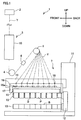
- FIG. 1 is a schematic view showing an example of a spun yarn take-up apparatus including an interlacing device.
- the spun yarn take-up apparatus 1 takes up synthetic-resin yarns Y spun out from a spinning apparatus 2 and forms packages P by winding the yarns Y onto bobbins B, respectively. It is noted that upward, downward, frontward, and backward directions shown in FIG. 1 will be used as upward, downward, frontward, and backward directions of the spun yarn take-up apparatus 1.
- the spun yarn take-up apparatus 1 includes members such as a drawing unit 3, take-up rollers 4 and 5, an interlacing device 6, and a winding device 7. To begin with, in the spinning apparatus 2, polymer supplied from a polymer supplier (not illustrated) formed of a gear pump or the like is pushed out downward from a spinneret, and yarns Y are spun out to be lined up in a direction away from the viewer of FIG. 1 .
- the yarns Y spun out from the spinning apparatus 2 run on a yarn path which is along a drawing unit 3, a take-up roller 4, an interlacing device 6, and a take-up roller 5, while being arranged to be lined up at proper yarn intervals by an unillustrated yarn path guide.
- the yarns Y are distributed in the front-back direction from the take-up roller 5, and are then wound onto the bobbins B, respectively, in the winding device 7.
- the drawing unit 3 is provided below the spinning apparatus 2.
- the drawing unit 3 includes a heat retaining box 10 and plural heating rollers (not illustrated) housed in the heat retaining box 10.
- the drawing unit 3 is configured to draw and heat the yarns Y spun out from the spinning apparatus 2, by the heating rollers.
- the yarns Y drawn by the drawing unit 3 are sent to the winding device 7 by the take-up rollers 4 and 5.
- the interlacing device 6 which is configured to interlace each of the yarns Y by entangling filaments constituting the yarn Y is provided. This interlacing device 6 will be detailed later.
- the winding device 7 includes members such as a base 11, a turret 12, two bobbin holders 13, a supporting frame 14, a contacting roller 15, and a traverse unit 16.
- the winding device 7 is configured to simultaneously wind the yarns Y supplied from the take-up roller 5 onto the bobbins B by rotating the bobbin holder 13, so as to form packages P.
- a disc-shaped turret 12 To the base 11 is attached a disc-shaped turret 12.
- the turret 12 is rotationally driven by an unillustrated motor.
- two long cylindrical bobbin holders 13 are cantilevered to extend in the front-back direction.
- the bobbins B To each bobbin holder 13, the bobbins B are attached to be lined up along the axis thereof.
- the two bobbin holders 13 are switched between an upper winding position and a lower retracted position.
- the supporting frame 14 is a long frame-shaped member extending in the front-back direction. This supporting frame 14 is fixedly attached to the base 11. At a lower part of the supporting frame 14, a roller supporting member 17 which is long in the front-back direction is attached to be movable in the up-down direction with respect to the supporting frame 14. By the roller supporting member 17, the contacting roller 15 which extends in the axial direction of the bobbin holder 13 is rotatably supported. This contacting roller 15 makes contact with a package P which is being formed, and the shape of the package P is adjusted as predetermined contact pressure is applied to the package P.
- the traverse unit 16 includes traverse guides 16a which are lined up in the front-back direction.
- the traverse guides 16a are driven by an unillustrated motor to reciprocate in the front-back direction, respectively.
- the yarns Y are wound onto the corresponding bobbins B while being traversed about fulcrum guides 18 in the front-back direction.
- FIG. 2 is a perspective view of the interlacing device 6.
- the interlacing device 6 includes an interlacing portion 20 configured to interlace the yarns Y, first regulatory portions 30 provided on the upstream and downstream in the yarn running direction of the interlacing portion 20, second regulatory portions 40 provided between the interlacing portion 20 and the first regulatory portions 30, and a base 50 supporting the interlacing portion 20, the first regulatory portions 30, and the second regulatory portions 40.
- the yarn paths of the yarns Y running in the interlacing portion 20 are defined by the first regulatory portions 30 and the second regulatory portions 40.
- the arrangement direction shown in FIG. 2 indicates a direction in which the yarns Y are lined up.
- the yarn running direction indicates a direction in which the yarns Y run, and is orthogonal to the arrangement direction in the present embodiment.
- the height direction is a direction in which the interlacing portion 20 protrudes from the base 50, and is orthogonal to the arrangement direction and the yarn running direction. While in the present embodiment the height direction is explained to be identical with the vertical direction for the sake of convenience, the height direction and the vertical direction are typically different from each other.
- the interlacing portion 20 is formed by providing interlacing pieces 21 each extending in the yarn running direction to be lined up in the arrangement direction.
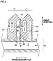
- FIG. 3 is a cross section showing the details of the interlacing pieces 21, taken at the center in the yarn running direction of two interlacing pieces 21 which neighbor each other in the arrangement direction.
- a yarn running space 22 is formed to penetrate the interlacing piece 21 in the yarn running direction.
- the cross sectional shape of the yarn running space 22 is an ellipse having a longer axis in parallel to the height direction, and the yarn Y runs in the yarn running direction at a substantial center of the space 22. As the fluid is ejected into the yarn running space 22, the yarns Y running in the yarn running space 22 are interlaced.
- the cross sectional shape of the yarn running space 22 may not be an ellipse, and may be a circle, a triangle, or the like.
- a yarn insertion space 24 is formed to be connected with the yarn running space 22 in the arrangement direction.
- the yarn insertion space 24 is positioned at a central part in the height direction of the yarn running space 22 and is formed across the entirety of the interlacing piece 21 in the yarn running direction.
- a fluid ejection orifice 26 is formed at a position substantially identical with the yarn insertion space 24 in the height direction. This fluid ejection orifice 26 is formed at a central part in the yarn running direction of the interlacing piece 21 and communicates with a fluid supply passage 27 formed in the interlacing piece 21.
- the two interlacing pieces 21 neighboring each other in the arrangement direction are disposed so that the yarn insertion surface 23 of the right interlacing piece 21 in FIG. 3 is in contact with the fluid ejection surface 25 of the left interlacing piece 21.
- the fluid ejection orifice 26 of the left interlacing piece 21 communicates with the yarn insertion space 24 of the right interlacing piece 21.
- a fluid supply path 51 is formed in the base 50 supporting the interlacing pieces 21, a fluid supply path 51 is formed in the base 50 supporting the interlacing pieces 21, a fluid supply ports 52 are formed in a surface (top surface) of the base 50 which surface supports the interlacing pieces 21, fluid supply ports 52 are formed. The upper end portion of each fluid supply port 52 is connected with the fluid supply passage 27 in the interlacing piece 21, whereas the lower end portion of each fluid supply port 52 is connected with the fluid supply path 51 in the base 50.
- the yarn insertion surface 23 is arranged in such a way that a part of the yarn insertion surface 23 above the yarn insertion space 24 is slightly deviated inward in the arrangement direction as compared to a part of the yarn insertion surface 23 below the yarn insertion space 24.
- a slit 28 is formed above the yarn insertion space 24 and between the two neighboring interlacing pieces 21. Through this slit 28 and the yarn insertion space 24, the yarn Y is provided in the yarn running space 22.
- fluid is supplied from an unillustrated fluid supplier to the fluid supply path 51 of the base 50.
- An example of the fluid includes compressed air.
- the fluid supplied to the fluid supply path 51 is ejected from the fluid ejection orifice 26 via the fluid supply port 52 and the fluid supply passage 27, and the ejected fluid is supplied to the yarn running space 22 via the yarn insertion space 24.
- the fluid supplier, the fluid supply path 51, the fluid supply port 52, the fluid supply passage 27, and the fluid ejection orifice 26 function as a fluid supplying unit for supplying the fluid to the yarn running space 22.
- FIG. 4 schematically shows the flow of the fluid in the yarn running space 22.
- the fluid ejected from the fluid supplying unit to the yarn running space 22 is branched into upper and lower branches upon collision with the inner wall of the yarn running space 22, with the result that rotational flows are generated.
- the yarn Y running in the yarn running space 22 is interlaced.
- the upstream and downstream branches in the yarn running direction of the fluid flowing in the yarn running space 22 are then discharged from the upstream and downstream end portions of the yarn running space 22 along the yarn running direction, and become jet flows.
- the jet flow from the yarn running space 22 collides with the first regulatory portion 30 or the second regulatory portion 40, a turbulent flow is generated and the running of the yarn Y becomes unstable. As a result, the yarns Y may be displaced from the original yarn paths and the interlacing may not be properly done.
- the first regulatory portions 30 and the second regulatory portions 40 are arranged as described below in the present embodiment.
- the first regulatory portions 30 are regulatory portions configured to regulate the yarns Y mainly in the arrangement direction, and are provided on the upstream and downstream in the yarn running direction of the interlacing portion 20, respectively.
- the first regulatory portions 30 protrude in the height direction from the base 50, and in each first regulatory portion 30, guide portions 31 each configured to sandwich the yarn Y from the both sides in the arrangement direction are provided to be lined up in the arrangement direction.
- Each guide portion 31 is provided with a U-shaped regulating groove 31a which extends in the height direction.
- Each yarn Y runs in the regulating groove 31a. As such, the regulation of the yarn Y is improved by regulating the running of the yarn Y by the regulating groove 31a which is deep and narrow and extends in the height direction.
- the second regulatory portions 40 provided between the interlacing portion 20 and the first regulatory portions 30 are regulatory portions configured to regulate the yarns Y mainly in the height direction.
- the second regulatory portions 40 are configured to additionally regulate the yarns Y in the arrangement direction as described below, by means of annular grooves 41a.
- Each second regulatory portion 40 is formed in such a way that a stick-shaped bar guide 41 extending in the arranging direction is supported by supporting members 42 which are provided at the respective end portions of the bar guide 41.
- the bar guide 41 is provided to be separated from the upper surface of the base 50, and an open space where the jet flow from the yarn running space 22 is able to pass is secured around the bar guide 41.
- the annular grooves 41a are formed to correspond to the respective yarns Y and to be lined up in the arrangement direction. Each yarn Y runs while being supported from below by the bottom portion of the annular groove 41a and being restrained from moving in the arrangement direction by the side portions of the annular groove 41a. It is noted that the annular grooves 41a of the second regulatory portions 40 are shallower than the regulating grooves 31a of the first regulatory portions 30, and the regulating capability of the second regulatory portion 40 for the yarn Y in the arrangement direction is less than the regulating capability of the first regulatory portion 30.
- FIG. 5A and 5B are cross section schematically showing the flows of the jet flows.
- FIG. 5A schematically shows the flows of jet flows by arrows in a case where only first regulatory portions 30 are provided as in a known technology
- FIG. 5B schematically shows the flows of jet flows by arrows in a case where the second regulatory portions 40 are provided in addition to the first regulatory portions 30 as in the present embodiment.
- the running of the yarns Y is regulated only by the first regulatory portions 30.
- the first regulatory portions 30 are provided with deep and narrow regulating grooves 31a, with the result that the first regulatory portions 30 are long in the height direction.
- the jet flow from the yarn running space 22 tends to collide with the first regulatory portion 30, and a turbulent flow generated by the collision makes the running of the yarns Y unstable.
- the first regulatory portion 30 may be provided to be away from the interlacing portion 20. In such a case, however, the regulating capability of the first regulatory portion 30 is deteriorated and hence the running of the yarns Y becomes unstable.
- the second regulatory portions 40 are provided between the interlacing portion 20 and the first regulatory portions 30.
- the regulating capability is enhanced by the second regulatory portion 40 even if the first regulatory portion 30 is arranged to be far enough from the interlacing portion 20 to sufficiently restrain the collision of the jet flow from the yarn running space 22 with the first regulatory portion 30.
- the second regulatory portion 40 is formed of the bar guide 41 and the open space 43 is secured above the bar guide 41 whereas the open space 44 is secured below the bar guide 41. For this reason, the jet flow from the yarn running space 22 is allowed to flow in the open spaces 43 and 44 so as to avoid the collision with the bar guide 41.
- the running of the yarns Y is regulated by the first regulatory portions 30 and the second regulatory portions 40, and the collision of the jet flows from the yarn running space 22 with the first regulatory portions 30 and the second regulatory portions 40 is avoided.
- the running of the yarns Y is therefore properly stabilized, and hence the interlacing capability is improved.
- the effect is particularly conspicuous when, as in the present embodiment, the interlacing device 6 interlaces the yarns Y lined up in the arrangement direction and the wall-shaped first regulatory portion 30 is formed by the guide portions 31 which are lined up in the arrangement direction.
- the interlacing device 6 interlaces the yarns Y lined up in the arrangement direction and the wall-shaped first regulatory portion 30 is formed by the guide portions 31 which are lined up in the arrangement direction.
- the second regulatory portion 40 is provided to be separated in the yarn running direction from the fluid ejection orifice 26 (see FIG. 3 ) formed at the center in the yarn running direction of the interlacing portion 20 (interlacing piece 21) by a distance which is not less than 30mm and not more than 50mm.
- the distance between the second regulatory portion 40 and the fluid ejection orifice 26 is less than 30mm, the interlacing portion 20 must be significantly short in the yarn running direction in order to prevent the interference between the interlacing portion 20 and the second regulatory portion 40, with the result that the interlacing capability of the interlacing portion 20 may be deteriorated.
- the regulating capability of the second regulatory portion 40 is deteriorated, with the result that the running of the yarns Y in the interlacing portion 20 becomes unstable and the yarns Y are not properly interlaced.
- the second regulatory portion 40 by arranging the second regulatory portion 40 to be separated from the fluid ejection orifice 26 by the distance which is not less than 30mm and not more than 50mm as described above, the yarns Y are properly interlaced by the interlacing portion 20.
- the length in the yarn running direction of the interlacing portion 20 (interlacing piece 21) is not less than 15mm and not more than 25mm, and the distance in the yarn running direction between the end face of the interlacing portion 20 (interlacing piece 21) and the second regulatory portion 40 is not less than 17.5mm and not more than 42.5mm.
- the distance in the yarn running direction between the first regulatory portion 30 and the second regulatory portion 40 is not less than 10mm and not more than 150mm.
- this distance is less than 10mm
- the influence of the collision of the jet flow with the first regulatory portion 30 reaches the second regulatory portion 40, with the result that the running of the yarn Y becomes unstable.
- the distance above is more than 150mm
- the regulating capability of the first regulatory portion 30 is deteriorated, with the result that the running of the yarn Y becomes unstable.
- the running of the yarns Y is stabilized and the yarns Y are properly interlaced when the distance between the first regulatory portion 30 and the second regulatory portion 40 is arranged to be not less than 10mm and not more than 150mm.
- the first regulatory portion 30 which is good in the regulating capability but with which the jet flow tends to collide is arranged to be away from the interlacing portion 20, and the regulating capability deteriorated by this arrangement is supplemented by the second regulatory portion 40 with which the jet flow rarely collides. On this account, the running of the yarns Y is properly stabilized.
- the running of the yarns Y in the interlacing portion 20 is further stabilized.
- the interlacing device 6 of the present embodiment is configured to interlace the yarns Y which run along the yarn running direction while being lined up in the arrangement direction
- the interlacing portion 20 includes the yarn running spaces 22 lined up in the arrangement direction and is configured to interlace the yarns Y running in the respective yarn running spaces 22 by ejecting fluid into the yarn running spaces 22.
- the first regulatory portions 30 are long in the arrangement direction because the yarns Y lined up in the arrangement direction are regulated. On this account, the jet flow from the yarn running space 22 tends to collide with each first regulatory portion 30, with the result that the running of the yarns Y becomes further unstable.
- the first regulatory portion 30 when the second regulatory portion 40 is provided between the interlacing portion 20 and the first regulatory portion 30, the first regulatory portion 30 is positioned to be away from the interlacing portion 20 while the decrease in the regulation of the yarn Y is restrained, with the result that the effect of stabilization of the running of the yarn Y becomes more conspicuous.
- the second regulatory portion 40 includes the stick-shaped bar guide 41 extending in the arrangement direction. On this account, the open spaces 43 and 44 are easily secured around the bar guide 41.
- the annular grooves (concave portions) 41a each of which sandwiches the yarn Y from the both sides in the arrangement direction are formed in the bar guide 41 to be lined up in the arrangement direction. For this reason, the swing of each yarn Y in the arrangement direction is restrained, and hence the running of the yarn Y is further stabilized.
- the interlacing device 6 is a so-called multi-type device configured to interlace plural yarns Y
- the interlacing device 6 may be a single-type device configured to interlace a single yarn Y.
- the first regulatory portion 30 is formed in such a way that guide portions 31 each of which sandwiches in the yarn Y from the both sides in the arrangement direction are lined up in the arrangement direction, the first regulatory portion 30 may not be specifically arranged in this way.
- column-shaped guides may be lined up in the arrangement direction as described in Patent Literature 1.
- the first regulatory portion 30 may be of any type on condition that it extends in the height direction and effectively regulates the running of the yarn Y by a deep and narrow regulating groove 31a or the like.
- the second regulatory portion 40 is formed of the bar guide 41 in which the annular grooves 41a are formed, the second regulatory portion 40 may not be specifically arranged in this way.
- the bar guide instead of the annular grooves 41a formed across the entire circumference of the bar guide 41, a notch-shaped concave portion may be formed only at a part where the yarn Y is regulated.
- the bar guide may not be provided with the annular groove 41a or the concave portion and simply support the yarn Y from below.
- the bar guide 41 may not have the circular cross section as shown in FIG. 5B , and may be flat with an elliptic cross sectional shape.
- first regulatory portions 30 and the second regulatory portions 40 are provided on the upstream and downstream in the yarn running direction of the interlacing portion 20.
- first regulatory portion 30 and the second regulatory portion 40 may be provided on only one side in the yarn running direction of the interlacing portion 20.
- the open space 44 below the bar guide 41 is formed between the bar guide 41 and the base 50.
- a space may be formed in a region of the base 50 below the bar guide 41 to penetrate the base 50 in the height direction, and such a space may be used as a substitute for the open space 44.
Landscapes
- Physics & Mathematics (AREA)
- Fluid Mechanics (AREA)
- Engineering & Computer Science (AREA)
- Textile Engineering (AREA)
- Yarns And Mechanical Finishing Of Yarns Or Ropes (AREA)
Abstract
Description
- The present invention relates to an interlacing device which is configured to interlace yarns.
- For example, Patent Literature 1 (
Japanese Unexamined Patent Publication No. 2005-179807 FIG. 2 ), and the running of the yarns is regulated by these regulating grooves. As such, the regulation of the yarns is ensured by regulating the running of the yarns by the deep and narrow regulating grooves. - The fluid ejected into the yarn running space of the interlacing portion flows upstream and downstream in the yarn running direction in the yarn running space, and is then discharged from upstream and downstream end portions. In this regard, when the guides extending in the height direction of the interlacing portion exist as in Patent Literature 1, the fluid discharged from the yarn running space (hereinafter, jet flow) collides with the guides and turbulent flow is generated, with the result that the running of the yarns becomes unstable. To avoid such a problem, the guides may be arranged to be sufficiently away from the interlacing portion. With this arrangement, however, the regulating capability of the guides is deteriorated and hence the running of the yarns becomes unstable.
- In consideration of the problem above, an object of an interlacing device of the present invention is to properly stabilize the running of yarns.
- The present invention relates to an interlacing device for interlacing yarns running along a yarn running direction, including: an interlacing portion which includes at least one yarn running space where the yarns run and is configured to interlace the yarns running in the at least one yarn running space by fluid ejected into the at least one yarn running space; a first regulatory portion which is provided on at least one of upstream and downstream in the yarn running direction of the interlacing portion and is configured to regulate running of the yarns; and a second regulatory portion which is provided between the interlacing portion and the first regulatory portion and is configured to regulate the running of the yarns, the first regulatory portion including a regulating groove extending in a height direction of the interlacing portion, and around the second regulatory portion, an open space where the fluid ejected from an end portion in the yarn running direction of the at least one yarn running space passes being provided.
- In the present invention, as regulatory portions for regulating the running of the yarns, the first regulatory portion and the second regulatory portion are provided. Because of the inclusion of the regulating groove extending in the height direction of the interlacing portion, the first regulatory portion is advantageous in terms of the regulating capability for the yarns. However, because the first regulatory portion extends in the height direction, a jet flow from the yarn running space tends to collide with the first regulatory portion, and hence a turbulent flow generated by the collision may cause the running of the yarns to be unstable. On this account, in the present invention, the second regulatory portion is provided between the interlacing portion and the first regulatory portion. With the second regulatory portion, the deterioration in the regulating capability for the yarns is supplemented by the second regulatory portion even if the first regulatory portion is arranged to be away from the interlacing portion so that the collision of the jet flow with the first regulatory portion is restrained. Furthermore, because the open space where the jet flow can pass is provided around the second regulatory portion, the jet flow passes the open space and hence the collision of the jet flow with the second regulatory portion is avoided. As described above, in the present invention, the first regulatory portion which is good in the regulating capability but with which the jet flow tends to collide is arranged to be away from the interlacing portion, and the regulating capability deteriorated by this arrangement is supplemented by the second regulatory portion with which the jet flow rarely collides. On this account, the running of the yarns is properly stabilized.
- Preferably, the first regulatory portion and the second regulatory portion are provided on the upstream and downstream in the yarn running direction of the interlacing portion.
- This further stabilizes the running of the yarns in the interlacing portion.
- The present invention is particularly effective when the interlacing device interlaces the yarns running in the yarn running direction while being lined up in an arrangement direction, and the interlacing portion includes a plurality of the at least one yarn running space lined up in the arrangement direction and interlaces the yarns running in the respective yarn running spaces by the fluid ejected into the respective yarn running spaces.
- This is because, in such a so-called multi-type interlacing device, the first regulatory portion is long in the arrangement direction as the yarns lined up in the arrangement direction are regulated. On this account, the jet flow from the yarn running space tends to collide with the first regulatory portion, and hence the running of the yarns becomes further unstable. In this case, when the second regulatory portion is provided between the interlacing portion and the first regulatory portion as described above, the first regulatory portion is positioned to be away from the interlacing portion while the decrease in the regulation of the yarns is restrained, with the result that the effect of stabilization of the running of the yarns becomes more conspicuous.
- Preferably, the second regulatory portion includes a stick-shaped bar guide which extends in the arrangement direction.
- As the second regulatory portion is formed of the bar guide, the open space is easily secured around the bar guide.
- Preferably, in the bar guide, concave portions each of which sandwiches each of the yarns from both sides in the arrangement direction are formed to be lined up in the arrangement direction.
- By providing these concave portions in the bar guide, the swing of each yarn in the arrangement direction is restrained, and hence the running of the yarns is further stabilized.
- In the present invention, because the second regulatory portion where the jet flow from the yarn running space can pass is provided between the interlacing portion and the first regulatory portion in addition to the first regulatory portion having high regulating capability for the yarns, the running of the yarns is properly stabilized.
-
-
FIG. 1 is a schematic view showing an example of a spun yarn take-up apparatus including an interlacing device. -
FIG. 2 is a perspective view of the interlacing device of the present embodiment. -
FIG. 3 is a cross section showing the interlacing piece in a detailed manner. -
FIG. 4 schematically shows the flow of fluid in the yarn running space. - Each of
FIGs. 5A and 5B is a cross section schematically showing the flows of jet flows. - The following will describe an embodiment of the present invention.
FIG. 1 is a schematic view showing an example of a spun yarn take-up apparatus including an interlacing device. The spun yarn take-up apparatus 1 takes up synthetic-resin yarns Y spun out from a spinningapparatus 2 and forms packages P by winding the yarns Y onto bobbins B, respectively. It is noted that upward, downward, frontward, and backward directions shown inFIG. 1 will be used as upward, downward, frontward, and backward directions of the spun yarn take-up apparatus 1. - The spun yarn take-up apparatus 1 includes members such as a drawing unit 3, take-
up rollers 4 and 5, aninterlacing device 6, and awinding device 7. To begin with, in thespinning apparatus 2, polymer supplied from a polymer supplier (not illustrated) formed of a gear pump or the like is pushed out downward from a spinneret, and yarns Y are spun out to be lined up in a direction away from the viewer ofFIG. 1 . - The yarns Y spun out from the spinning
apparatus 2 run on a yarn path which is along a drawing unit 3, a take-up roller 4, aninterlacing device 6, and a take-up roller 5, while being arranged to be lined up at proper yarn intervals by an unillustrated yarn path guide. The yarns Y are distributed in the front-back direction from the take-up roller 5, and are then wound onto the bobbins B, respectively, in thewinding device 7. - The drawing unit 3 is provided below the
spinning apparatus 2. The drawing unit 3 includes aheat retaining box 10 and plural heating rollers (not illustrated) housed in theheat retaining box 10. The drawing unit 3 is configured to draw and heat the yarns Y spun out from thespinning apparatus 2, by the heating rollers. - The yarns Y drawn by the drawing unit 3 are sent to the
winding device 7 by the take-up rollers 4 and 5. Between the take-up rollers 4 and 5, theinterlacing device 6 which is configured to interlace each of the yarns Y by entangling filaments constituting the yarn Y is provided. Thisinterlacing device 6 will be detailed later. - The
winding device 7 includes members such as abase 11, aturret 12, twobobbin holders 13, a supportingframe 14, a contactingroller 15, and atraverse unit 16. Thewinding device 7 is configured to simultaneously wind the yarns Y supplied from the take-up roller 5 onto the bobbins B by rotating thebobbin holder 13, so as to form packages P. - To the
base 11 is attached a disc-shaped turret 12. Theturret 12 is rotationally driven by an unillustrated motor. By theturret 12, two longcylindrical bobbin holders 13 are cantilevered to extend in the front-back direction. To eachbobbin holder 13, the bobbins B are attached to be lined up along the axis thereof. As theturret 12 rotates, the twobobbin holders 13 are switched between an upper winding position and a lower retracted position. - The supporting
frame 14 is a long frame-shaped member extending in the front-back direction. This supportingframe 14 is fixedly attached to thebase 11. At a lower part of the supportingframe 14, aroller supporting member 17 which is long in the front-back direction is attached to be movable in the up-down direction with respect to the supportingframe 14. By theroller supporting member 17, the contactingroller 15 which extends in the axial direction of thebobbin holder 13 is rotatably supported. This contactingroller 15 makes contact with a package P which is being formed, and the shape of the package P is adjusted as predetermined contact pressure is applied to the package P. - Directly above the contacting
roller 15 of theroller supporting member 17, thetraverse unit 16 is attached. Thetraverse unit 16 includes traverse guides 16a which are lined up in the front-back direction. The traverse guides 16a are driven by an unillustrated motor to reciprocate in the front-back direction, respectively. As the traverse guides 16a to which the yarns Y are threaded reciprocate, the yarns Y are wound onto the corresponding bobbins B while being traversed about fulcrum guides 18 in the front-back direction. - Now, the interlacing
device 6 will be detailed.FIG. 2 is a perspective view of the interlacingdevice 6. As shown inFIG. 2 , the interlacingdevice 6 includes an interlacingportion 20 configured to interlace the yarns Y, firstregulatory portions 30 provided on the upstream and downstream in the yarn running direction of the interlacingportion 20, secondregulatory portions 40 provided between the interlacingportion 20 and the firstregulatory portions 30, and a base 50 supporting the interlacingportion 20, the firstregulatory portions 30, and the secondregulatory portions 40. The yarn paths of the yarns Y running in the interlacingportion 20 are defined by the firstregulatory portions 30 and the secondregulatory portions 40. - In connection with the above, the arrangement direction shown in
FIG. 2 indicates a direction in which the yarns Y are lined up. The yarn running direction indicates a direction in which the yarns Y run, and is orthogonal to the arrangement direction in the present embodiment. The height direction is a direction in which the interlacingportion 20 protrudes from thebase 50, and is orthogonal to the arrangement direction and the yarn running direction. While in the present embodiment the height direction is explained to be identical with the vertical direction for the sake of convenience, the height direction and the vertical direction are typically different from each other. - The interlacing
portion 20 is formed by providing interlacingpieces 21 each extending in the yarn running direction to be lined up in the arrangement direction.FIG. 3 is a cross section showing the details of the interlacingpieces 21, taken at the center in the yarn running direction of two interlacingpieces 21 which neighbor each other in the arrangement direction. - In the interlacing
piece 21, ayarn running space 22 is formed to penetrate the interlacingpiece 21 in the yarn running direction. The cross sectional shape of theyarn running space 22 is an ellipse having a longer axis in parallel to the height direction, and the yarn Y runs in the yarn running direction at a substantial center of thespace 22. As the fluid is ejected into theyarn running space 22, the yarns Y running in theyarn running space 22 are interlaced. The cross sectional shape of theyarn running space 22 may not be an ellipse, and may be a circle, a triangle, or the like. - In a
yarn insertion surface 23 which is equivalent to the left surface of the interlacingpiece 21 inFIG. 3 , ayarn insertion space 24 is formed to be connected with theyarn running space 22 in the arrangement direction. Theyarn insertion space 24 is positioned at a central part in the height direction of theyarn running space 22 and is formed across the entirety of the interlacingpiece 21 in the yarn running direction. - In a
fluid ejection surface 25 which is equivalent to the right surface of the interlacingpiece 21 inFIG. 3 , afluid ejection orifice 26 is formed at a position substantially identical with theyarn insertion space 24 in the height direction. Thisfluid ejection orifice 26 is formed at a central part in the yarn running direction of the interlacingpiece 21 and communicates with afluid supply passage 27 formed in the interlacingpiece 21. - The two interlacing
pieces 21 neighboring each other in the arrangement direction are disposed so that theyarn insertion surface 23 of theright interlacing piece 21 inFIG. 3 is in contact with thefluid ejection surface 25 of theleft interlacing piece 21. With this arrangement, thefluid ejection orifice 26 of theleft interlacing piece 21 communicates with theyarn insertion space 24 of theright interlacing piece 21. - In addition to the above, in the base 50 supporting the interlacing
pieces 21, afluid supply path 51 is formed. Furthermore, in a surface (top surface) of the base 50 which surface supports the interlacingpieces 21,fluid supply ports 52 are formed. The upper end portion of eachfluid supply port 52 is connected with thefluid supply passage 27 in the interlacingpiece 21, whereas the lower end portion of eachfluid supply port 52 is connected with thefluid supply path 51 in thebase 50. - The
yarn insertion surface 23 is arranged in such a way that a part of theyarn insertion surface 23 above theyarn insertion space 24 is slightly deviated inward in the arrangement direction as compared to a part of theyarn insertion surface 23 below theyarn insertion space 24. On this account, when theyarn insertion surface 23 of theright interlacing piece 21 is in contact with thefluid ejection surface 25 of theleft interlacing piece 21, aslit 28 is formed above theyarn insertion space 24 and between the two neighboring interlacingpieces 21. Through this slit 28 and theyarn insertion space 24, the yarn Y is provided in theyarn running space 22. - To interlace the yarn Y running in the
yarn running space 22, fluid is supplied from an unillustrated fluid supplier to thefluid supply path 51 of thebase 50. An example of the fluid includes compressed air. The fluid supplied to thefluid supply path 51 is ejected from thefluid ejection orifice 26 via thefluid supply port 52 and thefluid supply passage 27, and the ejected fluid is supplied to theyarn running space 22 via theyarn insertion space 24. In other words, the fluid supplier, thefluid supply path 51, thefluid supply port 52, thefluid supply passage 27, and thefluid ejection orifice 26 function as a fluid supplying unit for supplying the fluid to theyarn running space 22. -
FIG. 4 schematically shows the flow of the fluid in theyarn running space 22. As indicated by the arrows inFIG. 4 , the fluid ejected from the fluid supplying unit to theyarn running space 22 is branched into upper and lower branches upon collision with the inner wall of theyarn running space 22, with the result that rotational flows are generated. By these flows of the fluid, the yarn Y running in theyarn running space 22 is interlaced. Thereafter, the upstream branch and the downstream branch in the yarn running direction of the fluid flow in theyarn running space 22 in a direction in parallel to the yarn Y. - The upstream and downstream branches in the yarn running direction of the fluid flowing in the
yarn running space 22 are then discharged from the upstream and downstream end portions of theyarn running space 22 along the yarn running direction, and become jet flows. When the jet flow from theyarn running space 22 collides with the firstregulatory portion 30 or the secondregulatory portion 40, a turbulent flow is generated and the running of the yarn Y becomes unstable. As a result, the yarns Y may be displaced from the original yarn paths and the interlacing may not be properly done. In consideration of this, the firstregulatory portions 30 and the secondregulatory portions 40 are arranged as described below in the present embodiment. - Referring back to
FIG. 2 , the firstregulatory portions 30 will be described. The firstregulatory portions 30 are regulatory portions configured to regulate the yarns Y mainly in the arrangement direction, and are provided on the upstream and downstream in the yarn running direction of the interlacingportion 20, respectively. The firstregulatory portions 30 protrude in the height direction from thebase 50, and in each firstregulatory portion 30, guideportions 31 each configured to sandwich the yarn Y from the both sides in the arrangement direction are provided to be lined up in the arrangement direction. Eachguide portion 31 is provided with aU-shaped regulating groove 31a which extends in the height direction. Each yarn Y runs in the regulatinggroove 31a. As such, the regulation of the yarn Y is improved by regulating the running of the yarn Y by the regulatinggroove 31a which is deep and narrow and extends in the height direction. - In the meanwhile, the second
regulatory portions 40 provided between the interlacingportion 20 and the firstregulatory portions 30 are regulatory portions configured to regulate the yarns Y mainly in the height direction. In the present embodiment, the secondregulatory portions 40 are configured to additionally regulate the yarns Y in the arrangement direction as described below, by means ofannular grooves 41a. Each secondregulatory portion 40 is formed in such a way that a stick-shapedbar guide 41 extending in the arranging direction is supported by supportingmembers 42 which are provided at the respective end portions of thebar guide 41. Thebar guide 41 is provided to be separated from the upper surface of thebase 50, and an open space where the jet flow from theyarn running space 22 is able to pass is secured around thebar guide 41. - In the circumferential surface of the
bar guide 41, theannular grooves 41a are formed to correspond to the respective yarns Y and to be lined up in the arrangement direction. Each yarn Y runs while being supported from below by the bottom portion of theannular groove 41a and being restrained from moving in the arrangement direction by the side portions of theannular groove 41a. It is noted that theannular grooves 41a of the secondregulatory portions 40 are shallower than the regulatinggrooves 31a of the firstregulatory portions 30, and the regulating capability of the secondregulatory portion 40 for the yarn Y in the arrangement direction is less than the regulating capability of the firstregulatory portion 30. - Each of
FIG. 5A and 5B is a cross section schematically showing the flows of the jet flows. To be more specific,FIG. 5A schematically shows the flows of jet flows by arrows in a case where only firstregulatory portions 30 are provided as in a known technology, whereasFIG. 5B schematically shows the flows of jet flows by arrows in a case where the secondregulatory portions 40 are provided in addition to the firstregulatory portions 30 as in the present embodiment. - As shown in
FIG. 5A , in the known technology, the running of the yarns Y is regulated only by the firstregulatory portions 30. To ensure the regulation of the yarns Y, the firstregulatory portions 30 are provided with deep andnarrow regulating grooves 31a, with the result that the firstregulatory portions 30 are long in the height direction. On this account, the jet flow from theyarn running space 22 tends to collide with the firstregulatory portion 30, and a turbulent flow generated by the collision makes the running of the yarns Y unstable. To avoid the collision of the jet flow with the firstregulatory portion 30, the firstregulatory portion 30 may be provided to be away from the interlacingportion 20. In such a case, however, the regulating capability of the firstregulatory portion 30 is deteriorated and hence the running of the yarns Y becomes unstable. - In consideration of the above, in the present embodiment, as shown in
FIG. 5B , the secondregulatory portions 40 are provided between the interlacingportion 20 and the firstregulatory portions 30. On this account, the regulating capability is enhanced by the secondregulatory portion 40 even if the firstregulatory portion 30 is arranged to be far enough from the interlacingportion 20 to sufficiently restrain the collision of the jet flow from theyarn running space 22 with the firstregulatory portion 30. Furthermore, the secondregulatory portion 40 is formed of thebar guide 41 and theopen space 43 is secured above thebar guide 41 whereas theopen space 44 is secured below thebar guide 41. For this reason, the jet flow from theyarn running space 22 is allowed to flow in theopen spaces bar guide 41. - As described above, in the present embodiment, the running of the yarns Y is regulated by the first
regulatory portions 30 and the secondregulatory portions 40, and the collision of the jet flows from theyarn running space 22 with the firstregulatory portions 30 and the secondregulatory portions 40 is avoided. The running of the yarns Y is therefore properly stabilized, and hence the interlacing capability is improved. - The effect is particularly conspicuous when, as in the present embodiment, the interlacing
device 6 interlaces the yarns Y lined up in the arrangement direction and the wall-shaped firstregulatory portion 30 is formed by theguide portions 31 which are lined up in the arrangement direction. This is because, when the jet flows from the respectiveyarn running spaces 22 collide with the wall-shaped firstregulatory portions 30 and influence on each other, the disturbance of air becomes significant and the running of the yarns Y may become further unstable. In this regard, in the present embodiment, because the collision of the jet flow with each firstregulatory portion 30 is restrained, the running of the yarns Y is certainly stabilized even in a so-calledmulti-type interlacing device 6. - In the present embodiment, the second
regulatory portion 40 is provided to be separated in the yarn running direction from the fluid ejection orifice 26 (seeFIG. 3 ) formed at the center in the yarn running direction of the interlacing portion 20 (interlacing piece 21) by a distance which is not less than 30mm and not more than 50mm. When the distance between the secondregulatory portion 40 and thefluid ejection orifice 26 is less than 30mm, the interlacingportion 20 must be significantly short in the yarn running direction in order to prevent the interference between the interlacingportion 20 and the secondregulatory portion 40, with the result that the interlacing capability of the interlacingportion 20 may be deteriorated. In the meanwhile, when the distance above is more than 50mm, the regulating capability of the secondregulatory portion 40 is deteriorated, with the result that the running of the yarns Y in the interlacingportion 20 becomes unstable and the yarns Y are not properly interlaced. For the reasons above, by arranging the secondregulatory portion 40 to be separated from thefluid ejection orifice 26 by the distance which is not less than 30mm and not more than 50mm as described above, the yarns Y are properly interlaced by the interlacingportion 20. In the present embodiment, the length in the yarn running direction of the interlacing portion 20 (interlacing piece 21) is not less than 15mm and not more than 25mm, and the distance in the yarn running direction between the end face of the interlacing portion 20 (interlacing piece 21) and the secondregulatory portion 40 is not less than 17.5mm and not more than 42.5mm. - In addition to the above, in the present embodiment, the distance in the yarn running direction between the first
regulatory portion 30 and the secondregulatory portion 40 is not less than 10mm and not more than 150mm. When this distance is less than 10mm, the influence of the collision of the jet flow with the firstregulatory portion 30 reaches the secondregulatory portion 40, with the result that the running of the yarn Y becomes unstable. In the meanwhile, when the distance above is more than 150mm, the regulating capability of the firstregulatory portion 30 is deteriorated, with the result that the running of the yarn Y becomes unstable. For these reasons, the running of the yarns Y is stabilized and the yarns Y are properly interlaced when the distance between the firstregulatory portion 30 and the secondregulatory portion 40 is arranged to be not less than 10mm and not more than 150mm. - As described above, in the present embodiment, the first
regulatory portion 30 which is good in the regulating capability but with which the jet flow tends to collide is arranged to be away from the interlacingportion 20, and the regulating capability deteriorated by this arrangement is supplemented by the secondregulatory portion 40 with which the jet flow rarely collides. On this account, the running of the yarns Y is properly stabilized. - In addition to the above, in the present embodiment, because the first
regulatory portions 30 and the secondregulatory portions 40 are provided on the upstream and downstream in the yarn running direction of the interlacingportion 20, the running of the yarns Y in the interlacingportion 20 is further stabilized. - In addition to the above, the interlacing
device 6 of the present embodiment is configured to interlace the yarns Y which run along the yarn running direction while being lined up in the arrangement direction, and the interlacingportion 20 includes theyarn running spaces 22 lined up in the arrangement direction and is configured to interlace the yarns Y running in the respectiveyarn running spaces 22 by ejecting fluid into theyarn running spaces 22. In such aninterlacing device 6 of a so-called multi-type, the firstregulatory portions 30 are long in the arrangement direction because the yarns Y lined up in the arrangement direction are regulated. On this account, the jet flow from theyarn running space 22 tends to collide with each firstregulatory portion 30, with the result that the running of the yarns Y becomes further unstable. In this arrangement, when the secondregulatory portion 40 is provided between the interlacingportion 20 and the firstregulatory portion 30, the firstregulatory portion 30 is positioned to be away from the interlacingportion 20 while the decrease in the regulation of the yarn Y is restrained, with the result that the effect of stabilization of the running of the yarn Y becomes more conspicuous. - In addition to the above, in the present embodiment, the second
regulatory portion 40 includes the stick-shapedbar guide 41 extending in the arrangement direction. On this account, theopen spaces bar guide 41. - In addition to the above, in the present embodiment, the annular grooves (concave portions) 41a each of which sandwiches the yarn Y from the both sides in the arrangement direction are formed in the
bar guide 41 to be lined up in the arrangement direction. For this reason, the swing of each yarn Y in the arrangement direction is restrained, and hence the running of the yarn Y is further stabilized. - Although the embodiment of the present invention has been described, the present invention is not limited to the above and can be suitably changed within the scope of the present invention as described in the examples below.
- For example, while in the embodiment above the interlacing
device 6 is a so-called multi-type device configured to interlace plural yarns Y, the interlacingdevice 6 may be a single-type device configured to interlace a single yarn Y. - In addition to the above, while in the embodiment above the first
regulatory portion 30 is formed in such a way that guideportions 31 each of which sandwiches in the yarn Y from the both sides in the arrangement direction are lined up in the arrangement direction, the firstregulatory portion 30 may not be specifically arranged in this way. For example, column-shaped guides may be lined up in the arrangement direction as described in Patent Literature 1. In other words, the firstregulatory portion 30 may be of any type on condition that it extends in the height direction and effectively regulates the running of the yarn Y by a deep andnarrow regulating groove 31a or the like. - While in the embodiment above the second
regulatory portion 40 is formed of thebar guide 41 in which theannular grooves 41a are formed, the secondregulatory portion 40 may not be specifically arranged in this way. For example, instead of theannular grooves 41a formed across the entire circumference of thebar guide 41, a notch-shaped concave portion may be formed only at a part where the yarn Y is regulated. Furthermore, the bar guide may not be provided with theannular groove 41a or the concave portion and simply support the yarn Y from below. Furthermore, thebar guide 41 may not have the circular cross section as shown inFIG. 5B , and may be flat with an elliptic cross sectional shape. - In addition to the above, in the embodiment above, the first
regulatory portions 30 and the secondregulatory portions 40 are provided on the upstream and downstream in the yarn running direction of the interlacingportion 20. Alternatively, the firstregulatory portion 30 and the secondregulatory portion 40 may be provided on only one side in the yarn running direction of the interlacingportion 20. - In addition to the above, in the embodiment above the
open space 44 below thebar guide 41 is formed between thebar guide 41 and thebase 50. Alternatively, a space may be formed in a region of thebase 50 below thebar guide 41 to penetrate the base 50 in the height direction, and such a space may be used as a substitute for theopen space 44.
Claims (6)
- An interlacing device for interlacing yarns running along a yarn running direction, comprising:an interlacing portion which includes at least one yarn running space where the yarns run and is configured to interlace the yarns running in the at least one yarn running space by fluid ejected into the at least one yarn running space;a first regulatory portion which is provided on at least one of upstream and downstream in the yarn running direction of the interlacing portion and is configured to regulate running of the yarns; anda second regulatory portion which is provided between the interlacing portion and the first regulatory portion and is configured to regulate the running of the yarns,the first regulatory portion including a regulating groove extending in a height direction of the interlacing portion, andaround the second regulatory portion, an open space where the fluid ejected from an end portion in the yarn running direction of the at least one yarn running space passes being provided.
- The interlacing device according to claim 1, wherein, the first regulatory portion and the second regulatory portion are provided on the upstream and downstream in the yarn running direction of the interlacing portion.
- The interlacing device according to claim 1 or 2 for interlacing the yarns running in the yarn running direction while being lined up in an arrangement direction, wherein,
the interlacing portion includes a plurality of the at least one yarn running space lined up in the arrangement direction, and interlaces the yarns running in the respective yarn running spaces by the fluid ejected into the respective yarn running spaces. - The interlacing device according to claim 3, wherein, the second regulatory portion includes a stick-shaped bar guide which extends in the arrangement direction.
- The interlacing device according to claim 4, wherein, in the bar guide, concave portions each of which sandwiches each of the yarns from both sides in the arrangement direction are formed to be lined up in the arrangement direction.
- The interlacing device according to any one of claims 1 to 5, wherein,
the second regulatory portion is provided to be distanced in the yarn running direction by 30mm or more and 50mm or less from a fluid ejection orifice formed in the interlacing portion, and
the distance in the yarn running direction between the first regulatory portion and the second regulatory portion is 10mm or more and 150mm or less.
Applications Claiming Priority (1)
| Application Number | Priority Date | Filing Date | Title |
|---|---|---|---|
| JP2015040189A JP6495051B2 (en) | 2015-03-02 | 2015-03-02 | Confounding device |
Publications (2)
| Publication Number | Publication Date |
|---|---|
| EP3064624A1 true EP3064624A1 (en) | 2016-09-07 |
| EP3064624B1 EP3064624B1 (en) | 2019-05-22 |
Family
ID=55521479
Family Applications (1)
| Application Number | Title | Priority Date | Filing Date |
|---|---|---|---|
| EP16157816.6A Active EP3064624B1 (en) | 2015-03-02 | 2016-02-29 | Interlacing device |
Country Status (3)
| Country | Link |
|---|---|
| EP (1) | EP3064624B1 (en) |
| JP (1) | JP6495051B2 (en) |
| CN (1) | CN105937075B (en) |
Cited By (4)
| Publication number | Priority date | Publication date | Assignee | Title |
|---|---|---|---|---|
| EP3444389A1 (en) * | 2017-08-18 | 2019-02-20 | TMT Machinery, Inc. | Interlacing device |
| CN111663211A (en) * | 2019-03-05 | 2020-09-15 | 欧瑞康纺织有限及两合公司 | Entanglement device for intertwining synthetic multifilament yarns |
| EP4119708A1 (en) * | 2021-07-13 | 2023-01-18 | TMT Machinery, Inc. | Interlacing device and yarn winder |
| EP4279647A1 (en) * | 2022-05-19 | 2023-11-22 | TMT Machinery, Inc. | Apparatus for treating yarns comprising a threading device |
Families Citing this family (6)
| Publication number | Priority date | Publication date | Assignee | Title |
|---|---|---|---|---|
| JP6495051B2 (en) * | 2015-03-02 | 2019-04-03 | Tmtマシナリー株式会社 | Confounding device |
| CN107142535B (en) * | 2017-07-12 | 2022-11-15 | 苏州龙杰特种纤维股份有限公司 | Spinning-in method of spinning winding device and spinning winding device |
| CN107628477A (en) * | 2017-09-14 | 2018-01-26 | 李丹 | A kind of take-up |
| JP7128572B2 (en) | 2017-12-13 | 2022-08-31 | Tmtマシナリー株式会社 | Entangling device |
| JP7580078B2 (en) * | 2021-02-16 | 2024-11-11 | Tmtマシナリー株式会社 | Intertwining device and yarn winding machine |
| JP7895823B2 (en) * | 2022-09-28 | 2026-07-28 | Tmtマシナリー株式会社 | Thread processing device |
Citations (9)
| Publication number | Priority date | Publication date | Assignee | Title |
|---|---|---|---|---|
| KR20010067626A (en) * | 2001-02-23 | 2001-07-13 | 김중호 | 12-end fiber Intermingle apparatus |
| JP2002105791A (en) * | 2000-09-22 | 2002-04-10 | Toray Ind Inc | Yarn entanglement processing device |
| DE10053073A1 (en) * | 2000-05-16 | 2002-05-08 | Barmag Barmer Maschf | Assembly for the production of melt spun thermoplastic filament, to produce more than six, has a tangling unit between the filament gathering guide and the drawing stage |
| JP2005179807A (en) | 2003-12-17 | 2005-07-07 | Toray Ind Inc | Yarn-like entanglement processing apparatus and entanglement processing method thereof |
| EP2055818A1 (en) * | 2007-10-30 | 2009-05-06 | TMT Machinery, Inc. | Interlacing device |
| US20090211219A1 (en) * | 2004-06-30 | 2009-08-27 | Buchmueller Patrick | Device and method for treating filament yarn and fancy knotted, migrated, and false-twist yarn |
| CN201648627U (en) * | 2010-03-04 | 2010-11-24 | 福建锦江科技有限公司 | Network point adding apparatus |
| CN202030887U (en) * | 2011-04-20 | 2011-11-09 | 绍兴文理学院 | Mesh box |
| KR20120024095A (en) * | 2010-09-06 | 2012-03-14 | 주식회사세라트랙 | The nozzle-equipment both as filament yarns migration and interlace |
Family Cites Families (2)
| Publication number | Priority date | Publication date | Assignee | Title |
|---|---|---|---|---|
| JP4742125B2 (en) * | 2008-08-06 | 2011-08-10 | Tmtマシナリー株式会社 | Multi yarn guide |
| JP6495051B2 (en) * | 2015-03-02 | 2019-04-03 | Tmtマシナリー株式会社 | Confounding device |
-
2015
- 2015-03-02 JP JP2015040189A patent/JP6495051B2/en active Active
-
2016
- 2016-02-29 EP EP16157816.6A patent/EP3064624B1/en active Active
- 2016-03-01 CN CN201610115549.4A patent/CN105937075B/en active Active
Patent Citations (9)
| Publication number | Priority date | Publication date | Assignee | Title |
|---|---|---|---|---|
| DE10053073A1 (en) * | 2000-05-16 | 2002-05-08 | Barmag Barmer Maschf | Assembly for the production of melt spun thermoplastic filament, to produce more than six, has a tangling unit between the filament gathering guide and the drawing stage |
| JP2002105791A (en) * | 2000-09-22 | 2002-04-10 | Toray Ind Inc | Yarn entanglement processing device |
| KR20010067626A (en) * | 2001-02-23 | 2001-07-13 | 김중호 | 12-end fiber Intermingle apparatus |
| JP2005179807A (en) | 2003-12-17 | 2005-07-07 | Toray Ind Inc | Yarn-like entanglement processing apparatus and entanglement processing method thereof |
| US20090211219A1 (en) * | 2004-06-30 | 2009-08-27 | Buchmueller Patrick | Device and method for treating filament yarn and fancy knotted, migrated, and false-twist yarn |
| EP2055818A1 (en) * | 2007-10-30 | 2009-05-06 | TMT Machinery, Inc. | Interlacing device |
| CN201648627U (en) * | 2010-03-04 | 2010-11-24 | 福建锦江科技有限公司 | Network point adding apparatus |
| KR20120024095A (en) * | 2010-09-06 | 2012-03-14 | 주식회사세라트랙 | The nozzle-equipment both as filament yarns migration and interlace |
| CN202030887U (en) * | 2011-04-20 | 2011-11-09 | 绍兴文理学院 | Mesh box |
Cited By (5)
| Publication number | Priority date | Publication date | Assignee | Title |
|---|---|---|---|---|
| EP3444389A1 (en) * | 2017-08-18 | 2019-02-20 | TMT Machinery, Inc. | Interlacing device |
| CN111663211A (en) * | 2019-03-05 | 2020-09-15 | 欧瑞康纺织有限及两合公司 | Entanglement device for intertwining synthetic multifilament yarns |
| CN111663211B (en) * | 2019-03-05 | 2023-08-29 | 欧瑞康纺织有限及两合公司 | Entanglement device for entangling synthetic multifilament yarns |
| EP4119708A1 (en) * | 2021-07-13 | 2023-01-18 | TMT Machinery, Inc. | Interlacing device and yarn winder |
| EP4279647A1 (en) * | 2022-05-19 | 2023-11-22 | TMT Machinery, Inc. | Apparatus for treating yarns comprising a threading device |
Also Published As
| Publication number | Publication date |
|---|---|
| CN105937075B (en) | 2020-02-21 |
| EP3064624B1 (en) | 2019-05-22 |
| CN105937075A (en) | 2016-09-14 |
| JP2016160550A (en) | 2016-09-05 |
| JP6495051B2 (en) | 2019-04-03 |
Similar Documents
| Publication | Publication Date | Title |
|---|---|---|
| EP3064624B1 (en) | Interlacing device | |
| EP2636625B1 (en) | Spun yarn take-up apparatus | |
| TWI471466B (en) | Multiple yarn guide | |
| EP2497732B1 (en) | Spinning winder | |
| EP2644548B1 (en) | Take-up apparatus and take-up facility | |
| CN103703175B (en) | Melt spinning device | |
| EP3444389B1 (en) | Interlacing device | |
| EP3498898B1 (en) | Interlacing device | |
| JP5600437B2 (en) | Spinning and winding equipment | |
| EP3093378B1 (en) | Oil supply guide and spun yarn take-up apparatus | |
| JP2007512444A (en) | Spinning equipment | |
| JP6027344B2 (en) | Textile machinery | |
| EP4119708A1 (en) | Interlacing device and yarn winder | |
| JP5738321B2 (en) | Device for drawing and winding a large number of synthetic yarns | |
| JP6334373B2 (en) | Confounding device | |
| EP3210919B1 (en) | Spun yarn take-up machine | |
| JP2007512445A (en) | Spinning equipment | |
| JP6352793B2 (en) | Confounding mechanism | |
| EP3800283B1 (en) | Yarn production system | |
| JP7656522B2 (en) | Spinning production equipment | |
| JP2022030820A (en) | Spinning takeoff machine | |
| EP4067544B1 (en) | Interlacing device and yarn winder | |
| EP4596767A1 (en) | Interlacing apparatus and spun yarn take-up machine | |
| JP2019055867A (en) | Filament winding equipment | |
| EP2184386B1 (en) | Device for melt-spinning and winding up synthetic filament yarns |
Legal Events
| Date | Code | Title | Description |
|---|---|---|---|
| PUAI | Public reference made under article 153(3) epc to a published international application that has entered the european phase |
Free format text: ORIGINAL CODE: 0009012 |
|
| AK | Designated contracting states |
Kind code of ref document: A1 Designated state(s): AL AT BE BG CH CY CZ DE DK EE ES FI FR GB GR HR HU IE IS IT LI LT LU LV MC MK MT NL NO PL PT RO RS SE SI SK SM TR |
|
| AX | Request for extension of the european patent |
Extension state: BA ME |
|
| 17P | Request for examination filed |
Effective date: 20161007 |
|
| RBV | Designated contracting states (corrected) |
Designated state(s): AL AT BE BG CH CY CZ DE DK EE ES FI FR GB GR HR HU IE IS IT LI LT LU LV MC MK MT NL NO PL PT RO RS SE SI SK SM TR |
|
| GRAP | Despatch of communication of intention to grant a patent |
Free format text: ORIGINAL CODE: EPIDOSNIGR1 |
|
| STAA | Information on the status of an ep patent application or granted ep patent |
Free format text: STATUS: GRANT OF PATENT IS INTENDED |
|
| RIC1 | Information provided on ipc code assigned before grant |
Ipc: D02J 1/08 20060101AFI20181212BHEP Ipc: B65H 57/16 20060101ALI20181212BHEP |
|
| INTG | Intention to grant announced |
Effective date: 20190108 |
|
| GRAS | Grant fee paid |
Free format text: ORIGINAL CODE: EPIDOSNIGR3 |
|
| GRAA | (expected) grant |
Free format text: ORIGINAL CODE: 0009210 |
|
| STAA | Information on the status of an ep patent application or granted ep patent |
Free format text: STATUS: THE PATENT HAS BEEN GRANTED |
|
| AK | Designated contracting states |
Kind code of ref document: B1 Designated state(s): AL AT BE BG CH CY CZ DE DK EE ES FI FR GB GR HR HU IE IS IT LI LT LU LV MC MK MT NL NO PL PT RO RS SE SI SK SM TR |
|
| REG | Reference to a national code |
Ref country code: GB Ref legal event code: FG4D |
|
| REG | Reference to a national code |
Ref country code: CH Ref legal event code: EP |
|
| REG | Reference to a national code |
Ref country code: IE Ref legal event code: FG4D |
|
| REG | Reference to a national code |
Ref country code: DE Ref legal event code: R096 Ref document number: 602016014156 Country of ref document: DE |
|
| REG | Reference to a national code |
Ref country code: AT Ref legal event code: REF Ref document number: 1136226 Country of ref document: AT Kind code of ref document: T Effective date: 20190615 |
|
| REG | Reference to a national code |
Ref country code: NL Ref legal event code: MP Effective date: 20190522 |
|
| REG | Reference to a national code |
Ref country code: LT Ref legal event code: MG4D |
|
| PG25 | Lapsed in a contracting state [announced via postgrant information from national office to epo] |
Ref country code: NO Free format text: LAPSE BECAUSE OF FAILURE TO SUBMIT A TRANSLATION OF THE DESCRIPTION OR TO PAY THE FEE WITHIN THE PRESCRIBED TIME-LIMIT Effective date: 20190822 Ref country code: HR Free format text: LAPSE BECAUSE OF FAILURE TO SUBMIT A TRANSLATION OF THE DESCRIPTION OR TO PAY THE FEE WITHIN THE PRESCRIBED TIME-LIMIT Effective date: 20190522 Ref country code: NL Free format text: LAPSE BECAUSE OF FAILURE TO SUBMIT A TRANSLATION OF THE DESCRIPTION OR TO PAY THE FEE WITHIN THE PRESCRIBED TIME-LIMIT Effective date: 20190522 Ref country code: LT Free format text: LAPSE BECAUSE OF FAILURE TO SUBMIT A TRANSLATION OF THE DESCRIPTION OR TO PAY THE FEE WITHIN THE PRESCRIBED TIME-LIMIT Effective date: 20190522 Ref country code: AL Free format text: LAPSE BECAUSE OF FAILURE TO SUBMIT A TRANSLATION OF THE DESCRIPTION OR TO PAY THE FEE WITHIN THE PRESCRIBED TIME-LIMIT Effective date: 20190522 Ref country code: ES Free format text: LAPSE BECAUSE OF FAILURE TO SUBMIT A TRANSLATION OF THE DESCRIPTION OR TO PAY THE FEE WITHIN THE PRESCRIBED TIME-LIMIT Effective date: 20190522 Ref country code: PT Free format text: LAPSE BECAUSE OF FAILURE TO SUBMIT A TRANSLATION OF THE DESCRIPTION OR TO PAY THE FEE WITHIN THE PRESCRIBED TIME-LIMIT Effective date: 20190922 Ref country code: SE Free format text: LAPSE BECAUSE OF FAILURE TO SUBMIT A TRANSLATION OF THE DESCRIPTION OR TO PAY THE FEE WITHIN THE PRESCRIBED TIME-LIMIT Effective date: 20190522 Ref country code: FI Free format text: LAPSE BECAUSE OF FAILURE TO SUBMIT A TRANSLATION OF THE DESCRIPTION OR TO PAY THE FEE WITHIN THE PRESCRIBED TIME-LIMIT Effective date: 20190522 |
|
| PG25 | Lapsed in a contracting state [announced via postgrant information from national office to epo] |
Ref country code: LV Free format text: LAPSE BECAUSE OF FAILURE TO SUBMIT A TRANSLATION OF THE DESCRIPTION OR TO PAY THE FEE WITHIN THE PRESCRIBED TIME-LIMIT Effective date: 20190522 Ref country code: GR Free format text: LAPSE BECAUSE OF FAILURE TO SUBMIT A TRANSLATION OF THE DESCRIPTION OR TO PAY THE FEE WITHIN THE PRESCRIBED TIME-LIMIT Effective date: 20190823 Ref country code: RS Free format text: LAPSE BECAUSE OF FAILURE TO SUBMIT A TRANSLATION OF THE DESCRIPTION OR TO PAY THE FEE WITHIN THE PRESCRIBED TIME-LIMIT Effective date: 20190522 Ref country code: BG Free format text: LAPSE BECAUSE OF FAILURE TO SUBMIT A TRANSLATION OF THE DESCRIPTION OR TO PAY THE FEE WITHIN THE PRESCRIBED TIME-LIMIT Effective date: 20190822 |
|
| REG | Reference to a national code |
Ref country code: AT Ref legal event code: MK05 Ref document number: 1136226 Country of ref document: AT Kind code of ref document: T Effective date: 20190522 |
|
| PG25 | Lapsed in a contracting state [announced via postgrant information from national office to epo] |
Ref country code: CZ Free format text: LAPSE BECAUSE OF FAILURE TO SUBMIT A TRANSLATION OF THE DESCRIPTION OR TO PAY THE FEE WITHIN THE PRESCRIBED TIME-LIMIT Effective date: 20190522 Ref country code: SK Free format text: LAPSE BECAUSE OF FAILURE TO SUBMIT A TRANSLATION OF THE DESCRIPTION OR TO PAY THE FEE WITHIN THE PRESCRIBED TIME-LIMIT Effective date: 20190522 Ref country code: RO Free format text: LAPSE BECAUSE OF FAILURE TO SUBMIT A TRANSLATION OF THE DESCRIPTION OR TO PAY THE FEE WITHIN THE PRESCRIBED TIME-LIMIT Effective date: 20190522 Ref country code: EE Free format text: LAPSE BECAUSE OF FAILURE TO SUBMIT A TRANSLATION OF THE DESCRIPTION OR TO PAY THE FEE WITHIN THE PRESCRIBED TIME-LIMIT Effective date: 20190522 Ref country code: DK Free format text: LAPSE BECAUSE OF FAILURE TO SUBMIT A TRANSLATION OF THE DESCRIPTION OR TO PAY THE FEE WITHIN THE PRESCRIBED TIME-LIMIT Effective date: 20190522 Ref country code: AT Free format text: LAPSE BECAUSE OF FAILURE TO SUBMIT A TRANSLATION OF THE DESCRIPTION OR TO PAY THE FEE WITHIN THE PRESCRIBED TIME-LIMIT Effective date: 20190522 |
|
| REG | Reference to a national code |
Ref country code: DE Ref legal event code: R097 Ref document number: 602016014156 Country of ref document: DE |
|
| PG25 | Lapsed in a contracting state [announced via postgrant information from national office to epo] |
Ref country code: SM Free format text: LAPSE BECAUSE OF FAILURE TO SUBMIT A TRANSLATION OF THE DESCRIPTION OR TO PAY THE FEE WITHIN THE PRESCRIBED TIME-LIMIT Effective date: 20190522 Ref country code: IT Free format text: LAPSE BECAUSE OF FAILURE TO SUBMIT A TRANSLATION OF THE DESCRIPTION OR TO PAY THE FEE WITHIN THE PRESCRIBED TIME-LIMIT Effective date: 20190522 |
|
| PLBE | No opposition filed within time limit |
Free format text: ORIGINAL CODE: 0009261 |
|
| STAA | Information on the status of an ep patent application or granted ep patent |
Free format text: STATUS: NO OPPOSITION FILED WITHIN TIME LIMIT |
|
| PG25 | Lapsed in a contracting state [announced via postgrant information from national office to epo] |
Ref country code: TR Free format text: LAPSE BECAUSE OF FAILURE TO SUBMIT A TRANSLATION OF THE DESCRIPTION OR TO PAY THE FEE WITHIN THE PRESCRIBED TIME-LIMIT Effective date: 20190522 |
|
| 26N | No opposition filed |
Effective date: 20200225 |
|
| PG25 | Lapsed in a contracting state [announced via postgrant information from national office to epo] |
Ref country code: PL Free format text: LAPSE BECAUSE OF FAILURE TO SUBMIT A TRANSLATION OF THE DESCRIPTION OR TO PAY THE FEE WITHIN THE PRESCRIBED TIME-LIMIT Effective date: 20190522 |
|
| PG25 | Lapsed in a contracting state [announced via postgrant information from national office to epo] |
Ref country code: SI Free format text: LAPSE BECAUSE OF FAILURE TO SUBMIT A TRANSLATION OF THE DESCRIPTION OR TO PAY THE FEE WITHIN THE PRESCRIBED TIME-LIMIT Effective date: 20190522 |
|
| REG | Reference to a national code |
Ref country code: CH Ref legal event code: PL |
|
| GBPC | Gb: european patent ceased through non-payment of renewal fee |
Effective date: 20200229 |
|
| REG | Reference to a national code |
Ref country code: BE Ref legal event code: MM Effective date: 20200229 |
|
| PG25 | Lapsed in a contracting state [announced via postgrant information from national office to epo] |
Ref country code: LU Free format text: LAPSE BECAUSE OF NON-PAYMENT OF DUE FEES Effective date: 20200229 Ref country code: MC Free format text: LAPSE BECAUSE OF FAILURE TO SUBMIT A TRANSLATION OF THE DESCRIPTION OR TO PAY THE FEE WITHIN THE PRESCRIBED TIME-LIMIT Effective date: 20190522 |
|
| PG25 | Lapsed in a contracting state [announced via postgrant information from national office to epo] |
Ref country code: LI Free format text: LAPSE BECAUSE OF NON-PAYMENT OF DUE FEES Effective date: 20200229 Ref country code: CH Free format text: LAPSE BECAUSE OF NON-PAYMENT OF DUE FEES Effective date: 20200229 |
|
| PG25 | Lapsed in a contracting state [announced via postgrant information from national office to epo] |
Ref country code: FR Free format text: LAPSE BECAUSE OF NON-PAYMENT OF DUE FEES Effective date: 20200229 Ref country code: GB Free format text: LAPSE BECAUSE OF NON-PAYMENT OF DUE FEES Effective date: 20200229 Ref country code: IE Free format text: LAPSE BECAUSE OF NON-PAYMENT OF DUE FEES Effective date: 20200229 |
|
| PG25 | Lapsed in a contracting state [announced via postgrant information from national office to epo] |
Ref country code: BE Free format text: LAPSE BECAUSE OF NON-PAYMENT OF DUE FEES Effective date: 20200229 |
|
| PG25 | Lapsed in a contracting state [announced via postgrant information from national office to epo] |
Ref country code: MT Free format text: LAPSE BECAUSE OF FAILURE TO SUBMIT A TRANSLATION OF THE DESCRIPTION OR TO PAY THE FEE WITHIN THE PRESCRIBED TIME-LIMIT Effective date: 20190522 Ref country code: CY Free format text: LAPSE BECAUSE OF FAILURE TO SUBMIT A TRANSLATION OF THE DESCRIPTION OR TO PAY THE FEE WITHIN THE PRESCRIBED TIME-LIMIT Effective date: 20190522 |
|
| PG25 | Lapsed in a contracting state [announced via postgrant information from national office to epo] |
Ref country code: MK Free format text: LAPSE BECAUSE OF FAILURE TO SUBMIT A TRANSLATION OF THE DESCRIPTION OR TO PAY THE FEE WITHIN THE PRESCRIBED TIME-LIMIT Effective date: 20190522 Ref country code: IS Free format text: LAPSE BECAUSE OF FAILURE TO SUBMIT A TRANSLATION OF THE DESCRIPTION OR TO PAY THE FEE WITHIN THE PRESCRIBED TIME-LIMIT Effective date: 20190922 |
|
| P01 | Opt-out of the competence of the unified patent court (upc) registered |
Effective date: 20230426 |
|
| PGFP | Annual fee paid to national office [announced via postgrant information from national office to epo] |
Ref country code: DE Payment date: 20260225 Year of fee payment: 11 |