EP3064458B1 - A magazine for sheet packaging blanks - Google Patents
A magazine for sheet packaging blanks Download PDFInfo
- Publication number
- EP3064458B1 EP3064458B1 EP15157201.3A EP15157201A EP3064458B1 EP 3064458 B1 EP3064458 B1 EP 3064458B1 EP 15157201 A EP15157201 A EP 15157201A EP 3064458 B1 EP3064458 B1 EP 3064458B1
- Authority
- EP
- European Patent Office
- Prior art keywords
- main
- magazine
- packaging elements
- auxiliary
- conveying space
- Prior art date
- Legal status (The legal status is an assumption and is not a legal conclusion. Google has not performed a legal analysis and makes no representation as to the accuracy of the status listed.)
- Active
Links
Images


Classifications
-
- B—PERFORMING OPERATIONS; TRANSPORTING
- B65—CONVEYING; PACKING; STORING; HANDLING THIN OR FILAMENTARY MATERIAL
- B65H—HANDLING THIN OR FILAMENTARY MATERIAL, e.g. SHEETS, WEBS, CABLES
- B65H1/00—Supports or magazines for piles from which articles are to be separated
- B65H1/02—Supports or magazines for piles from which articles are to be separated adapted to support articles on edge
- B65H1/025—Supports or magazines for piles from which articles are to be separated adapted to support articles on edge with controlled positively-acting mechanical devices for advancing the pile to present the articles to the separating device
-
- B—PERFORMING OPERATIONS; TRANSPORTING
- B65—CONVEYING; PACKING; STORING; HANDLING THIN OR FILAMENTARY MATERIAL
- B65H—HANDLING THIN OR FILAMENTARY MATERIAL, e.g. SHEETS, WEBS, CABLES
- B65H1/00—Supports or magazines for piles from which articles are to be separated
- B65H1/30—Supports or magazines for piles from which articles are to be separated with means for replenishing the pile during continuous separation of articles therefrom
-
- B—PERFORMING OPERATIONS; TRANSPORTING
- B65—CONVEYING; PACKING; STORING; HANDLING THIN OR FILAMENTARY MATERIAL
- B65H—HANDLING THIN OR FILAMENTARY MATERIAL, e.g. SHEETS, WEBS, CABLES
- B65H5/00—Feeding articles separated from piles; Feeding articles to machines
- B65H5/02—Feeding articles separated from piles; Feeding articles to machines by belts or chains, e.g. between belts or chains
- B65H5/028—Feeding articles separated from piles; Feeding articles to machines by belts or chains, e.g. between belts or chains by chains
-
- B—PERFORMING OPERATIONS; TRANSPORTING
- B65—CONVEYING; PACKING; STORING; HANDLING THIN OR FILAMENTARY MATERIAL
- B65H—HANDLING THIN OR FILAMENTARY MATERIAL, e.g. SHEETS, WEBS, CABLES
- B65H2301/00—Handling processes for sheets or webs
- B65H2301/30—Orientation, displacement, position of the handled material
- B65H2301/32—Orientation of handled material
- B65H2301/323—Hanging
-
- B—PERFORMING OPERATIONS; TRANSPORTING
- B65—CONVEYING; PACKING; STORING; HANDLING THIN OR FILAMENTARY MATERIAL
- B65H—HANDLING THIN OR FILAMENTARY MATERIAL, e.g. SHEETS, WEBS, CABLES
- B65H2404/00—Parts for transporting or guiding the handled material
- B65H2404/30—Chains
- B65H2404/31—Chains with auxiliary handling means
- B65H2404/311—Blades, lugs, plates, paddles, fingers
- B65H2404/3111—Blades, lugs, plates, paddles, fingers on two opposite chains or set of chains, i.e. having active handling section cooperating with and facing to each other
-
- B—PERFORMING OPERATIONS; TRANSPORTING
- B65—CONVEYING; PACKING; STORING; HANDLING THIN OR FILAMENTARY MATERIAL
- B65H—HANDLING THIN OR FILAMENTARY MATERIAL, e.g. SHEETS, WEBS, CABLES
- B65H2701/00—Handled material; Storage means
- B65H2701/10—Handled articles or webs
- B65H2701/17—Nature of material
- B65H2701/176—Cardboard
- B65H2701/1764—Cut-out, single-layer, e.g. flat blanks for boxes
-
- B—PERFORMING OPERATIONS; TRANSPORTING
- B65—CONVEYING; PACKING; STORING; HANDLING THIN OR FILAMENTARY MATERIAL
- B65H—HANDLING THIN OR FILAMENTARY MATERIAL, e.g. SHEETS, WEBS, CABLES
- B65H2801/00—Application field
- B65H2801/81—Packaging machines
Definitions
- the present invention relates to a magazine for sheet packaging elements, in particular for cardboard blanks designed to be transformed into packaging boxes housing multiple packages or containers and adapted to be delivered to sales outlets.
- the present invention may be advantageously but not exclusively used in plants for packaging pourable food products, such as beverages, milk, wine, tomato sauce, etc., in sealed packages, containers or the like, which are then packed in groups into the above-mentioned packaging boxes.
- pourable food products such as beverages, milk, wine, tomato sauce, etc.
- the said sealed packages or containers are formed, filled and sealed in a machine or a combination of machines and are then conveyed to an end packaging station, in which the sealed packages or containers are packaged in groups into packaging boxes.
- packaging boxes are formed from respective sheet packaging elements, which are stored in a magazine and picked up from the latter to be then subjected to folding operations in the end packaging station.
- Packaging elements are typically defined by plane, rectangular or square blanks, which, in some cases, may also be provided with handles to ease transportation of the resulting packaging boxes.
- Each handle is in general applied to one of the opposite faces of a relative packaging element so as to protrude from the latter.
- the presence of handles may cause the packaging elements to fan out and so compromise the stackability of the packaging elements in a magazine.
- a need particularly felt within the industry is to keep the packaging elements stored in the magazine with given orientations, so that they can be picked up in the right way to be fed to the end packaging station and to be subjected to folding operations in such station.
- Another need particularly felt within the industry is to provide a correct distribution of the packaging elements in the magazine irrespective of their initial loading so as to ensure a correct feeding of the packaging elements themselves to the end packaging station.
- US3999683 dislcoses a carton loading and forming machine having a carton dispenser magazine which includes a walking beam mechanism arranged to underlie portions of the carton blanks in the magazine for moving the carton blanks towards the discharge end of the magazine.
- the magazine is adapted to suspend the blanks from support rails disposed at opposite sides of the blanks and arranged above the center of gravity of the blanks so that the blanks hang freely from the support rails.
- Number 1 in Figures 1 and 2 indicates as a whole a magazine 1 for sheet packaging elements 2, in particular cardboard blanks designed to be transformed into packaging boxes (known per se and not shown) housing multiple packages or containers (known per se and not shown).
- each packaging element 2 has a plane configuration and presents substantially a rectangular profile.
- Each packaging element 2 is also provided with at least two lateral cuts or recesses 4, which are formed on opposite sides or edge portions 4a of the packaging element 2 and are configured to interact with the magazine 1 as it will be explained in greater detail hereafter.
- each packaging element 2 may also comprise a handle protruding from one face of the packaging element 2 or from an edge thereof.
- magazine 1 basically comprises:
- Auxiliary conveying unit 9 is preferably controlled independently from main conveying unit 6.
- magazine 1 may comprise solely main conveying unit 6 mounted on support structure 5.
- packaging elements 2 should be loaded into magazine 1 in segmented batches 3 having given spacing between each other.
- magazine 1 may comprise main conveying unit 6 and two or more auxiliary conveying units 9 arranged downstream of the main conveying unit 6 and separated from each other by respective accumulation units 8.
- main conveying unit 6 and two or more auxiliary conveying units 9 arranged downstream of the main conveying unit 6 and separated from each other by respective accumulation units 8.
- auxiliary conveying units 9 arranged downstream of the main conveying unit 6 and separated from each other by respective accumulation units 8.
- main conveying unit 6 comprises two main conveyors 14 arranged side by side and having respective horizontal main transport branches 15, in turn defining a main conveying space 16, in which packaging elements 2 are advanced towards accumulation unit 8 and auxiliary conveying unit 9.
- auxiliary conveying unit 9 comprises two auxiliary conveyors 17 arranged side by side and having respective horizontal auxiliary transport branches 18 in turn defining an auxiliary conveying space 19, in which packaging elements 2 are advanced from accumulation unit 8 to outlet section 12.
- Auxiliary transport branches 18 are aligned with respective main transport branches 15 so as to define respective extensions thereof towards outlet section 12.
- Accumulation unit 8 comprises two fixed support branches 20 adapted to support packaging elements 2 in the transition from main conveying unit 6 to auxiliary conveying unit 9 and arranged side by side as well as aligned with respective main transport branches 15 and auxiliary transport branches 18 so as to define an accumulation space 21 interposed between main conveying space 16 and auxiliary conveying spaces 19.
- main conveying space 16, accumulation space 21 and auxiliary conveying space 19 respectively define a first portion PI, a second portion P2 and a third portion P3 of a path P, which extends from inlet section 7 to outlet section 12 and along which packaging elements 2 are conveyed towards the end packaging station.
- Path P preferably has a rectilinear configuration parallel to main transport branches 15 and auxiliary transport branches 18 and to support branches 20.
- support structure 5 comprises:
- Base frame 22 rests on the floor through a plurality of height-adjustable feet 24, four in the example shown.
- Base frame 22 comprises two longitudinal supporting beams 25 and two transverse supporting beams 26.
- longitudinal supporting beams 25 extend parallel to path P and have respective intermediate portions 29a carrying fixed support branches 20; transverse supporting beams 26 extend orthogonally to path P and to the longitudinal supporting beams 25.
- Each vertical frame 23 is movably mounted on transverse supporting beams 26 of base frame 22 in a direction orthogonal to path P. In this way, by varying the position of vertical frames 23 on base frame 22, it is possible to adjust the width of main conveying space 16 and auxiliary conveying space 19 as well as of accumulation space 21 in a direction orthogonal to path P and as a function of the size of packaging elements 2 handled by magazine 1.
- Each vertical frame 23 comprises two vertical struts 27, a lower longitudinal supporting bar 28 and an upper longitudinal supporting bar 29.
- Vertical struts 27 of each vertical frame 23 are mounted on respective transverse supporting beams 26 by means of respective sliders 30.
- Actuator means 33 are provided to move sliders 30 of each vertical frame 23 simultaneously along respective transverse supporting beams 26.
- each one of the actuator means 33 comprise:
- Each one of the actuator means 33 further comprises an operating handle 36 to put into rotation one of screw actuators 34 of the relative vertical frame 23, and a transmission mechanism 37 to transmit rotation imparted by operating handle 36 to the other screw actuator 34.
- Transmission mechanism 37 preferably comprises a longitudinal shaft 38, which extends parallel and adjacent to the respective longitudinal supporting beam 25 and has, at its opposite ends, respective bevel gears 39 meshing with corresponding bevel gears 40 carried by respective screw actuators 34.
- bevel gears 40 are mounted on respective end portions of screw actuators 34 opposite the threaded end portions engaging nut-screw elements 35.
- each main conveyor 14 is of chain-type and is mounted on upper longitudinal supporting bar 29 of the respective vertical frame 23.
- Each main conveyor 14 comprises a toothed driving pulley 41, a toothed driven pulley 42 and an endless chain 45 wound about respective pulleys 41 and 42.
- pulleys 41, 42 have respective vertical axes A, B parallel to struts 27 of the relative vertical frame 23 and orthogonal to path P and to upper longitudinal supporting bars 25 of the vertical frame 23.
- Each chain 45 advantageously lies on a substantially horizontal plane.
- Each chain 45 comprises:
- Each chain 45 comprises a plurality of links 48 which define respective flaps 50 protruding horizontally into main conveying space 16 when being on the relative main transport branch 15.
- Flaps 50 of main transport branches 15 of main conveyors 14 are adapted to engage respective recesses 4 of packaging elements 2 and to support these latter elements in vertical positions ( Figures 2 and 4 ), in which they are partially housed in main conveying space 16 and extend orthogonally to the main transport branches 15 themselves and to path P.
- each flap 50 comprises a root portion 51, connected through rods (known per se and not shown) to the root portions 51 of the adjacent flaps 50, and an engaging portion 52, protruding into main conveying space 16 when being on main transport branch 15 to engage a corresponding recess 4 of a respective packaging element 2.
- All flaps 50 preferably lie on a common horizontal plane, which is orthogonal in use to packaging elements 2 advanced by main conveyors 14.
- engaging portions 52 of flaps 50 of main transport branches 15 are inclined with respect to path P. More specifically, the engaging portions 52 of the flaps 50 of one of main transport branches 15 and the engaging portions 52 of the flaps 50 of the other main transport branch 15 are converging to each other in a direction opposite the advancing direction of packaging elements 2 along path P. In this way, support of packaging elements 2 is always guaranteed even in the transition of flaps 50 from main transport branches 15 to the adjacent curved connection portions 47 of the respective chains 45.
- each main conveyor 14 is actuated by a drive motor 55 fixedly secured to a lower face of the respective upper longitudinal supporting bar 29; in the example shown, motors 55 are located in the vicinity of accumulation unit 8 and are directly coupled to respective pulleys 41.
- auxiliary conveyors 17 present essentially the same configurations as main conveyors 14; for the sake of simplicity and conciseness, all components of auxiliary conveyors 17 are indicated in the Figures with the same numerals as the corresponding ones of main conveyors 14 and are not further described.
- drive motors 55 of auxiliary conveyors 17 are located in the vicinity of outlet section 12.
- drive motors 55 of auxiliary conveyors 17 are controlled independently of drive motors 55 of main conveyors 14.
- accumulation unit 8 comprises stopping means 56 carried by intermediate portions 29a of upper longitudinal supporting bar 29, arranged between main conveyors 14 and auxiliary conveyors 17 with respect to path P and selectively actuated to stop in use advancement of packaging elements 2 from main conveying space 16 to auxiliary conveying space 19 in such a way that an accumulation of the packaging elements 2 is generated in use at the exit of main conveying space 16, i.e. in accumulation space 21 and, if necessary, at the outlet region of the main conveying space 16 itself.
- Stopping means 56 comprise two stopping elements 57 suspended on the lower faces of intermediate portions 29a of respective upper longitudinal supporting bars 29 and movable towards, and away from, each other between an operative position ( Figure 6 ), in which the stopping elements 57 protrude into accumulation space 21 to interfere with advancement of packaging elements 2 along path P, and a rest position ( Figure 7 ), in which the stopping elements 57 are retracted from accumulation space 21 and allow movement of the packaging elements 2 along path P.
- each stopping element 57 is sandwiched between a first plate 58, secured to the lower face of the intermediate portion 29a of the relative upper longitudinal supporting bar 29, and a second plate 59, secured to the plate 58 at a given vertical distance therefrom to allow movements of the stopping element 57 itself between the rest position and the operative position; more specifically, first plate 58 and second plate 59 are connected to one another by a plurality of spacers 60.
- each stopping element 57 Movement of each stopping element 57 is guided by two slots 61, 62 formed on plate 59 and slidably engaged by respective pins 63, 64 protruding from the stopping element 57 itself.
- each stopping element 57 is defined by an L-shaped plate parallel to plates 58 and 59.
- Each stopping element 57 comprises a guiding portion 65, extending - in the rest position - parallel to path P as well as to upper longitudinal supporting bars 29 and provided with pins 63, 64, and a stopping portion 66, extending transversally from an end region of guiding portion 65 and adapted to protrude into accumulation space 21 in the operative position to stop packaging elements 2.
- Pins 63, 64 extend orthogonally from the relative stopping element 57 to engage respective slots 61, 62 of plate 59; more precisely, pin 63 protrudes from an end region of guiding portion 65 opposite the end region from which stopping portion 66 extends; pin 64 is instead arranged at an intermediate location of guiding portion 65 between pin 63 and stopping portion 66.
- slot 61 of each plate 59 has a linear configuration and extends parallel to path P and to upper longitudinal supporting bars 29; slot 62 of each plate 59 has a first linear portion 70 aligned with the relative slot 61 and a second linear portion 71, slanted with respect to linear portion 70 and diverging from the linear portion 71 of the corresponding slot 62 formed on the other plate 59 in the advancement direction of packaging elements 2 along path P.
- a linear actuator 72 in the example shown a fluidic actuator, is secured to plate 59 on the opposite side of plate 58 and comprises a piston rod 73 moving parallel to path P and having a free end connected to pin 63. Linear movements of piston rod 73 in the opposite directions parallel to path P produce, through interaction of pin 64 with slot 62, movement of the relative stopping element 57 between the rest position and the operative position.
- packaging elements 2 are loaded or fed into main conveying space 16 from inlet section 7 of magazine 1. Flaps 50 of main transport branches 15 protruding into main conveying space 16 engage respective recesses 4 of packaging elements 2 and support these latter elements in vertical position. Packaging elements 2 may be loaded or fed into main conveying space 16 at any spacing therebetween.
- each actuating operating handle 36 puts the respective screw actuator 34 to which it is directly coupled into rotation along its longitudinal axis and by means of transmission mechanism 37 also the other screw actuator 34 is put into rotation along its longitudinal axis. Screw actuators 34 cooperate with respective nut-screw elements 35 which move respective sliders 30 along transverse supporting beams 26 orthogonally to path P and therewith also moving the respective vertical frame 23 orthogonally to path P.
- Vertical frames 23 can be moved independently of each other by actuating the respective operating handles 36; in this way, the upper longitudinal supporting bars 29 and correspondingly main conveyors 14 and auxiliary conveyors 17, are moved towards or away from each other, thus, decreasing or increasing the width of main space 16, auxiliary conveying space 19 and accumulation space 21.
- Stopping elements 57 may be actuated, simultaneously, from their rest positions to their operative positions by activating respective linear actuators 72 and, thereby, inducing linear movements of respective piston rods 73.
- piston rods 73 are moved in opposite directions with respect to path P towards inlet section 7.
- guiding portions 65 of stopping elements 57 are moved in cooperation with respective piston rods 73, pins 63, 64 and slots 61 and 62, so that stopping elements 57 are driven to their operative positions, in particular protruding into accumulation space 21.
- stopping elements 57 interfere with advancement of packaging elements 2 so as to allow compacting the desired number of packaging elements 2 to form one batch 3.
- piston rods 73 of respective linear actuators 72 are moved towards outlet section 12, thereby driving stopping elements 57 into their rest positions.
- magazine 1 allows conveying packaging elements 2 in an ordered sequence and in vertical position so that a possible presence of handles on the packaging elements 2 would not prejudice stacking of packaging elements 2 as it is the case when packaging elements 2 are e.g. horizontally oriented. In this latter case, stacked packaging elements 2 would inevitably present a tendency to fan out, which may limit further processing.
- magazine 1 functionality of magazine 1 is independent with respect to the way in which packaging elements 2 are loaded or fed into inlet section 7.
- packaging elements 2 may be loaded in main conveying unit 6 at any arbitrary spacing, thereby, simplifying the work of operators. They are advanced along path P towards accumulation unit 8, in which packaging elements 2 become compacted, and, in cooperation with auxiliary conveying unit 9, as described further above, they are grouped in batches 3 having the desired size and numerousness.
- the number of packaging elements 2 and the spacing between adjacent batches 3 can be varied as a function of the operating conditions of the end packaging station, which receives batches 3 at outlet section 12 and where packaging elements 2 become folded into packaging boxes.
- flaps 30 having their engaging portions 52 inclined with respect to path P. This allows that packaging elements 2 are continuously supported during transitions from main conveying unit 6 to accumulation unit 8 and from accumulation unit 8 to auxiliary conveying unit 9.
Landscapes
- Engineering & Computer Science (AREA)
- Mechanical Engineering (AREA)
- Feeding Of Articles By Means Other Than Belts Or Rollers (AREA)
- Sheets, Magazines, And Separation Thereof (AREA)
- Making Paper Articles (AREA)
Description
- The present invention relates to a magazine for sheet packaging elements, in particular for cardboard blanks designed to be transformed into packaging boxes housing multiple packages or containers and adapted to be delivered to sales outlets.
- The present invention may be advantageously but not exclusively used in plants for packaging pourable food products, such as beverages, milk, wine, tomato sauce, etc., in sealed packages, containers or the like, which are then packed in groups into the above-mentioned packaging boxes.
- The present description refers to this specific field, although this is in no way intended to limit the scope of protection as defined by the accompanying claims.
- As known, the said sealed packages or containers are formed, filled and sealed in a machine or a combination of machines and are then conveyed to an end packaging station, in which the sealed packages or containers are packaged in groups into packaging boxes.
- Conveniently, packaging boxes are formed from respective sheet packaging elements, which are stored in a magazine and picked up from the latter to be then subjected to folding operations in the end packaging station.
- Packaging elements are typically defined by plane, rectangular or square blanks, which, in some cases, may also be provided with handles to ease transportation of the resulting packaging boxes.
- Each handle is in general applied to one of the opposite faces of a relative packaging element so as to protrude from the latter. The presence of handles may cause the packaging elements to fan out and so compromise the stackability of the packaging elements in a magazine.
- A need particularly felt within the industry is to keep the packaging elements stored in the magazine with given orientations, so that they can be picked up in the right way to be fed to the end packaging station and to be subjected to folding operations in such station.
- Another need particularly felt within the industry is to provide a correct distribution of the packaging elements in the magazine irrespective of their initial loading so as to ensure a correct feeding of the packaging elements themselves to the end packaging station.
-
US3999683 dislcoses a carton loading and forming machine having a carton dispenser magazine which includes a walking beam mechanism arranged to underlie portions of the carton blanks in the magazine for moving the carton blanks towards the discharge end of the magazine. The magazine is adapted to suspend the blanks from support rails disposed at opposite sides of the blanks and arranged above the center of gravity of the blanks so that the blanks hang freely from the support rails. - It is therefore an object of the present invention to provide a magazine for sheet packaging elements which allows satisfying at least one of the aforementioned needs.
- According to the present invention, there is provided a magazine as claimed in
claim 1. - A preferred, non-limiting embodiment of the present invention will be described by way of example with reference to the accompanying drawings, in which:
-
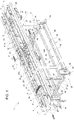
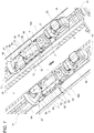
Figure 1 shows a perspective view of a magazine for sheet packaging elements according to the present invention, with parts removed for clarity; -
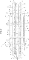
Figure 2 shows a top plan view of the magazine ofFigure 1 , with parts removed for clarity; -
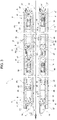
Figure 3 shows a larger-scale top plan view of the magazine ofFigures 1 and2 , with parts removed for clarity; -
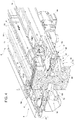
Figure 4 shows a larger-scale perspective view of portion of the magazine ofFigure 1 , sectioned along plane IV-IV; -
Figure 5 shows a larger-scale perspective view of a detail of the portion of the magazine ofFigure 4 ; -
Figures 6 and7 show larger-scale bottom perspective views of the portion of the magazine ofFigure 4 , in different operating conditions and with parts removed for clarity; and -
Figure 8 shows a larger-scale bottom perspective view of another portion of the magazine ofFigures 1 and2 . -
Number 1 inFigures 1 and2 indicates as a whole amagazine 1 forsheet packaging elements 2, in particular cardboard blanks designed to be transformed into packaging boxes (known per se and not shown) housing multiple packages or containers (known per se and not shown). - As shown in
Figures 1 and2 , eachpackaging element 2 has a plane configuration and presents substantially a rectangular profile. Eachpackaging element 2 is also provided with at least two lateral cuts orrecesses 4, which are formed on opposite sides oredge portions 4a of thepackaging element 2 and are configured to interact with themagazine 1 as it will be explained in greater detail hereafter. - According to a possible alternative not shown, each
packaging element 2 may also comprise a handle protruding from one face of thepackaging element 2 or from an edge thereof. - With reference to
Figures 1 to 3 ,magazine 1 basically comprises: - a
support structure 5; - a
main conveying unit 6 mounted onsupport structure 5 and receivingpackaging elements 2 at aninlet section 7 to advance them within themagazine 1; - an
accumulation unit 8 carried bysupport structure 5 downstream ofmain conveying unit 6 and adapted to form multiple spaced batches 3 (only one shown inFigures 1 and4 ), each defined by a plurality ofadjacent packaging elements 2; and - an
auxiliary conveying unit 9 mounted onsupport structure 5 downstream ofaccumulation unit 8 and configured to receive spacedbatches 3 ofpackaging elements 2 fromaccumulation unit 8 and to advance them to anoutlet section 12, in which thepackaging elements 2 are fed to an end packaging station (known per se and not shown) for folding them so as to form the above-mentioned packaging boxes. -
Auxiliary conveying unit 9 is preferably controlled independently frommain conveying unit 6. - According to a possible alternative embodiment of the present invention not shown,
magazine 1 may comprise solelymain conveying unit 6 mounted onsupport structure 5. In this case,packaging elements 2 should be loaded intomagazine 1 in segmentedbatches 3 having given spacing between each other. - According to another possible embodiment of the present invention not shown,
magazine 1 may comprisemain conveying unit 6 and two or moreauxiliary conveying units 9 arranged downstream of themain conveying unit 6 and separated from each other byrespective accumulation units 8. In this case, it would be possible to change the number ofpackaging elements 2 forming thebatches 3 by passing from oneauxiliary conveying unit 6 to the following one. - With reference to
Figures 1 to 3 ,main conveying unit 6 comprises twomain conveyors 14 arranged side by side and having respective horizontalmain transport branches 15, in turn defining amain conveying space 16, in whichpackaging elements 2 are advanced towardsaccumulation unit 8 andauxiliary conveying unit 9. - In a completely analogous manner,
auxiliary conveying unit 9 comprises twoauxiliary conveyors 17 arranged side by side and having respective horizontalauxiliary transport branches 18 in turn defining anauxiliary conveying space 19, in whichpackaging elements 2 are advanced fromaccumulation unit 8 tooutlet section 12.Auxiliary transport branches 18 are aligned with respectivemain transport branches 15 so as to define respective extensions thereof towardsoutlet section 12. -
Accumulation unit 8 comprises twofixed support branches 20 adapted to supportpackaging elements 2 in the transition frommain conveying unit 6 toauxiliary conveying unit 9 and arranged side by side as well as aligned with respectivemain transport branches 15 andauxiliary transport branches 18 so as to define anaccumulation space 21 interposed betweenmain conveying space 16 andauxiliary conveying spaces 19. - As visible in
Figures 1 to 3 ,main conveying space 16,accumulation space 21 andauxiliary conveying space 19 respectively define a first portion PI, a second portion P2 and a third portion P3 of a path P, which extends frominlet section 7 tooutlet section 12 and along whichpackaging elements 2 are conveyed towards the end packaging station. - Path P preferably has a rectilinear configuration parallel to
main transport branches 15 andauxiliary transport branches 18 and to supportbranches 20. - With reference to
Figures 1 ,2 and8 ,support structure 5 comprises: - a fixed
horizontal base frame 22; and - two movable
vertical frames 23, each one supporting a relativemain conveyor 14 and a relativeauxiliary conveyor 17 arranged on the same side with respect to path P. -
Base frame 22 rests on the floor through a plurality of height-adjustable feet 24, four in the example shown. -
Base frame 22 comprises two longitudinal supportingbeams 25 and two transverse supportingbeams 26. In particular, longitudinal supportingbeams 25 extend parallel to path P and have respectiveintermediate portions 29a carryingfixed support branches 20; transverse supportingbeams 26 extend orthogonally to path P and to the longitudinal supportingbeams 25. - Each
vertical frame 23 is movably mounted on transverse supportingbeams 26 ofbase frame 22 in a direction orthogonal to path P. In this way, by varying the position ofvertical frames 23 onbase frame 22, it is possible to adjust the width ofmain conveying space 16 andauxiliary conveying space 19 as well as ofaccumulation space 21 in a direction orthogonal to path P and as a function of the size ofpackaging elements 2 handled bymagazine 1. - Each
vertical frame 23 comprises twovertical struts 27, a lower longitudinal supportingbar 28 and an upper longitudinal supportingbar 29.Vertical struts 27 of eachvertical frame 23 are mounted on respective transverse supportingbeams 26 by means ofrespective sliders 30. - Actuator means 33 are provided to move
sliders 30 of eachvertical frame 23 simultaneously along respective transverse supportingbeams 26. - As shown in
Figures 1 to 3 and8 , each one of the actuator means 33 comprise: - a
screw actuators 34 mounted parallel and adjacent to respective transverse supportingbeams 26 and adapted to rotate about their axes; and - two nut-
screw elements 35 secured torespective sliders 30 and engaged by respective threaded end portions ofscrew actuator 34 to transform the rotation of thescrew actuator 34 itself into linear movements of thesliders 30 along the respectivetransverse support beams 26. - Each one of the actuator means 33 further comprises an
operating handle 36 to put into rotation one ofscrew actuators 34 of the relativevertical frame 23, and atransmission mechanism 37 to transmit rotation imparted byoperating handle 36 to theother screw actuator 34. -
Transmission mechanism 37 preferably comprises alongitudinal shaft 38, which extends parallel and adjacent to the respective longitudinal supportingbeam 25 and has, at its opposite ends,respective bevel gears 39 meshing withcorresponding bevel gears 40 carried byrespective screw actuators 34. - In particular,
bevel gears 40 are mounted on respective end portions ofscrew actuators 34 opposite the threaded end portions engaging nut-screw elements 35. - With reference to
Figures 1 to 3 , eachmain conveyor 14 is of chain-type and is mounted on upper longitudinal supportingbar 29 of the respectivevertical frame 23. - Each
main conveyor 14 comprises atoothed driving pulley 41, a toothed drivenpulley 42 and anendless chain 45 wound aboutrespective pulleys - In particular,
pulleys struts 27 of the relativevertical frame 23 and orthogonal to path P and to upper longitudinal supportingbars 25 of thevertical frame 23. - Each
chain 45 advantageously lies on a substantially horizontal plane. - Each
chain 45 comprises: - the relative
main transport branch 15, which is adjacent tomain conveying space 16; - a
main return branch 46, which is parallel to themain transport branch 15 and is arranged on the opposite side thereof with respect tomain conveying space 16; and -
curved connection portions 47, which connect respective end portions of themain transport branch 15 to corresponding end portions of themain return branch 46. - Each
chain 45 comprises a plurality oflinks 48 which definerespective flaps 50 protruding horizontally into main conveyingspace 16 when being on the relativemain transport branch 15. -
Flaps 50 ofmain transport branches 15 ofmain conveyors 14 are adapted to engagerespective recesses 4 ofpackaging elements 2 and to support these latter elements in vertical positions (Figures 2 and4 ), in which they are partially housed in main conveyingspace 16 and extend orthogonally to themain transport branches 15 themselves and to path P. - More specifically, each
flap 50 comprises aroot portion 51, connected through rods (known per se and not shown) to theroot portions 51 of theadjacent flaps 50, and an engagingportion 52, protruding into main conveyingspace 16 when being onmain transport branch 15 to engage acorresponding recess 4 of arespective packaging element 2. - All flaps 50 preferably lie on a common horizontal plane, which is orthogonal in use to
packaging elements 2 advanced bymain conveyors 14. - As visible in particular in
Figures 1 to 3 , engagingportions 52 offlaps 50 ofmain transport branches 15 are inclined with respect to path P. More specifically, the engagingportions 52 of theflaps 50 of one ofmain transport branches 15 and the engagingportions 52 of theflaps 50 of the othermain transport branch 15 are converging to each other in a direction opposite the advancing direction ofpackaging elements 2 along path P. In this way, support ofpackaging elements 2 is always guaranteed even in the transition offlaps 50 frommain transport branches 15 to the adjacentcurved connection portions 47 of therespective chains 45. - As shown in
Figure 1 , eachmain conveyor 14 is actuated by adrive motor 55 fixedly secured to a lower face of the respective upper longitudinal supportingbar 29; in the example shown,motors 55 are located in the vicinity ofaccumulation unit 8 and are directly coupled torespective pulleys 41. - With reference to
Figures 1 to 3 ,auxiliary conveyors 17 present essentially the same configurations asmain conveyors 14; for the sake of simplicity and conciseness, all components ofauxiliary conveyors 17 are indicated in the Figures with the same numerals as the corresponding ones ofmain conveyors 14 and are not further described. - In this case, drive
motors 55 ofauxiliary conveyors 17 are located in the vicinity ofoutlet section 12. - It is pointed out that
drive motors 55 ofauxiliary conveyors 17 are controlled independently ofdrive motors 55 ofmain conveyors 14. - With reference to
Figures 4 to 7 ,accumulation unit 8 comprises stopping means 56 carried byintermediate portions 29a of upper longitudinal supportingbar 29, arranged betweenmain conveyors 14 andauxiliary conveyors 17 with respect to path P and selectively actuated to stop in use advancement ofpackaging elements 2 from main conveyingspace 16 toauxiliary conveying space 19 in such a way that an accumulation of thepackaging elements 2 is generated in use at the exit of main conveyingspace 16, i.e. inaccumulation space 21 and, if necessary, at the outlet region of the main conveyingspace 16 itself. - Stopping means 56 comprise two stopping
elements 57 suspended on the lower faces ofintermediate portions 29a of respective upper longitudinal supportingbars 29 and movable towards, and away from, each other between an operative position (Figure 6 ), in which the stoppingelements 57 protrude intoaccumulation space 21 to interfere with advancement ofpackaging elements 2 along path P, and a rest position (Figure 7 ), in which the stoppingelements 57 are retracted fromaccumulation space 21 and allow movement of thepackaging elements 2 along path P. - In particular, each stopping
element 57 is sandwiched between afirst plate 58, secured to the lower face of theintermediate portion 29a of the relative upper longitudinal supportingbar 29, and asecond plate 59, secured to theplate 58 at a given vertical distance therefrom to allow movements of the stoppingelement 57 itself between the rest position and the operative position; more specifically,first plate 58 andsecond plate 59 are connected to one another by a plurality ofspacers 60. - Movement of each stopping
element 57 is guided by twoslots plate 59 and slidably engaged byrespective pins element 57 itself. - In greater details, each stopping
element 57 is defined by an L-shaped plate parallel toplates element 57 comprises a guidingportion 65, extending - in the rest position - parallel to path P as well as to upper longitudinal supportingbars 29 and provided withpins portion 66, extending transversally from an end region of guidingportion 65 and adapted to protrude intoaccumulation space 21 in the operative position to stoppackaging elements 2. -
Pins element 57 to engagerespective slots plate 59; more precisely, pin 63 protrudes from an end region of guidingportion 65 opposite the end region from which stoppingportion 66 extends;pin 64 is instead arranged at an intermediate location of guidingportion 65 betweenpin 63 and stoppingportion 66. - As visible in detail in
Figures 6 and7 , slot 61 of eachplate 59 has a linear configuration and extends parallel to path P and to upper longitudinal supportingbars 29;slot 62 of eachplate 59 has a firstlinear portion 70 aligned with therelative slot 61 and a secondlinear portion 71, slanted with respect tolinear portion 70 and diverging from thelinear portion 71 of thecorresponding slot 62 formed on theother plate 59 in the advancement direction ofpackaging elements 2 along path P. - A
linear actuator 72, in the example shown a fluidic actuator, is secured to plate 59 on the opposite side ofplate 58 and comprises apiston rod 73 moving parallel to path P and having a free end connected to pin 63. Linear movements ofpiston rod 73 in the opposite directions parallel to path P produce, through interaction ofpin 64 withslot 62, movement of the relative stoppingelement 57 between the rest position and the operative position. - In use,
packaging elements 2 are loaded or fed into main conveyingspace 16 frominlet section 7 ofmagazine 1.Flaps 50 ofmain transport branches 15 protruding into main conveyingspace 16 engagerespective recesses 4 ofpackaging elements 2 and support these latter elements in vertical position.Packaging elements 2 may be loaded or fed into main conveyingspace 16 at any spacing therebetween. - Prior to loading or feeding
packaging elements 2 intomagazine 1, the width of main conveyingspace 16 and correspondingly of auxiliary conveyingspace 19 andaccumulation space 21 may be adapted with respect to the size ofpackaging elements 2. Eachactuating operating handle 36 puts the respective screw actuator 34 to which it is directly coupled into rotation along its longitudinal axis and by means oftransmission mechanism 37 also theother screw actuator 34 is put into rotation along its longitudinal axis.Screw actuators 34 cooperate with respective nut-screw elements 35 which moverespective sliders 30 along transverse supportingbeams 26 orthogonally to path P and therewith also moving the respectivevertical frame 23 orthogonally to path P. Vertical frames 23 can be moved independently of each other by actuating the respective operating handles 36; in this way, the upper longitudinal supportingbars 29 and correspondinglymain conveyors 14 andauxiliary conveyors 17, are moved towards or away from each other, thus, decreasing or increasing the width ofmain space 16,auxiliary conveying space 19 andaccumulation space 21. -
Motors 55 ofmain conveyors 14, which are synchronized with each other, driverespective pulleys 41, hence, putting into movementrespective chains 45; as a consequence, flaps 50 of respectivemain transport branches 15 are also moved along portion P1 of path P, thereby advancingpackaging elements 2 towardsaccumulation unit 8. In the proximity ofaccumulation unit 8, flaps 50 ofmain conveyors 14release packaging elements 2 which are supported in the same vertical positions bysupport branches 20. - In this condition, further advancement of
packaging elements 2 located inaccumulation unit 8 is obtained by the pushing action exerted by thepackaging elements 2 upstream ofaccumulation unit 8 and exiting from main conveyingspace 16. - Stopping
elements 57 may be actuated, simultaneously, from their rest positions to their operative positions by activating respectivelinear actuators 72 and, thereby, inducing linear movements ofrespective piston rods 73. In particular,piston rods 73 are moved in opposite directions with respect to path P towardsinlet section 7. Correspondingly, guidingportions 65 of stoppingelements 57 are moved in cooperation withrespective piston rods 73, pins 63, 64 andslots elements 57 are driven to their operative positions, in particular protruding intoaccumulation space 21. - As set in their operative positions, stopping
elements 57 interfere with advancement ofpackaging elements 2 so as to allow compacting the desired number ofpackaging elements 2 to form onebatch 3. In particular, after having formed the desiredbatch 3 ofpackaging elements 2,piston rods 73 of respectivelinear actuators 72 are moved towardsoutlet section 12, thereby driving stoppingelements 57 into their rest positions. - By continuing to drive
motors 55 ofmain conveyors 14, and consequently the correspondingflaps 50 ofmain transport branches 15,packaging elements 2 forming the desiredbatch 3 are pushed fromaccumulation unit 8 toauxiliary unit 9. - There, in a completely analogous manner, movement of
chains 45 ofauxiliary conveyors 17 produces advancement of the formedbatch 3 ofpackaging elements 2 along portion P3 of path P towardsoutlet section 12. - Repeating the above described steps leads to generate a plurality of
batches 3 ofpackaging elements 2 spaced apart from each other and advanced towards the end packaging station for performing the necessary folding operations to form packaging boxes. - The advantages of
magazine 1 according to the present invention will be clear from the foregoing description. - In particular,
magazine 1 allows conveyingpackaging elements 2 in an ordered sequence and in vertical position so that a possible presence of handles on thepackaging elements 2 would not prejudice stacking ofpackaging elements 2 as it is the case when packagingelements 2 are e.g. horizontally oriented. In this latter case, stackedpackaging elements 2 would inevitably present a tendency to fan out, which may limit further processing. - In addition, debris from
packaging elements 2 or other contaminations fall off from thepackaging elements 2 during advancement thereof withinmagazine 1 and, hence, they do not accumulate in between theadjacent packaging elements 2 themselves. - Moreover, functionality of
magazine 1 is independent with respect to the way in whichpackaging elements 2 are loaded or fed intoinlet section 7. - In particular,
packaging elements 2 may be loaded in main conveyingunit 6 at any arbitrary spacing, thereby, simplifying the work of operators. They are advanced along path P towardsaccumulation unit 8, in whichpackaging elements 2 become compacted, and, in cooperation with auxiliary conveyingunit 9, as described further above, they are grouped inbatches 3 having the desired size and numerousness. - Additionally, the number of
packaging elements 2 and the spacing betweenadjacent batches 3 can be varied as a function of the operating conditions of the end packaging station, which receivesbatches 3 atoutlet section 12 and wherepackaging elements 2 become folded into packaging boxes. - An even further advantage lies in the independent control of
drive motors 55 of main conveyingunit 6 andauxiliary conveying unit 9 which permit to further adapt the advancement of thebatches 3 as well as their spacing to the operation conditions of the end packaging station. Thus, the feeding ofbatches 3 is not affected by the spacing at whichpackaging elements 2 are loaded or fed into main conveyingunit 6. - In addition, a further advantage arises from
flaps 30 having their engagingportions 52 inclined with respect to path P. This allows thatpackaging elements 2 are continuously supported during transitions from main conveyingunit 6 toaccumulation unit 8 and fromaccumulation unit 8 to auxiliary conveyingunit 9. - Clearly, changes may be made to
magazine 1 as described herein without, however, departing from the scope of protection as defined in the accompanying claims.
Claims (13)
- A magazine (1) for sheet packaging elements (2), comprising at least two main conveyors (14) arranged side by side, defining a main conveying space (16) for said packaging elements (2) and having respective horizontal main transport branches (15) configured to cooperate in use with respective side portions (4a) of said packaging elements (2), so as to support said packaging elements (2) in vertical positions, in which said packaging elements (2) are partially housed in said main conveying space (16) and extend transversally to said main transport branches (15), and to advance said packaging elements (2) along a path (P) parallel to said main transport branches (15), each main transport branch (15) comprises a plurality of engaging portions (52) protruding into the main conveying space (16) and configured to cooperate in use with lateral recesses (4) made in the side portions (4a) of the packaging elements (2), characterized in that each main conveyor (14) is of chain-type, and said engaging portions (52) define at least partially respective links (48) of said main conveyor (14).
- The magazine as claimed in claim 1, wherein the engaging portions (52) of said main transport branches (15) lie in a common horizontal plane which is orthogonal in use to said packaging elements (2).
- The magazine as claimed in claim 1 or 2, wherein said engaging portions (52) of said main transport branches (14) are inclined with respect to said path (P) .
- The magazine as claimed in any one of the foregoing claims, wherein the engaging portions (52) of one of said main transport branches (15) and the engaging portions (52) of the other main transport branch (15) are converging to each other.
- The magazine as claimed in any one of the foregoing claims, and further comprising at least two auxiliary conveyors (17) arranged side by side and having respective auxiliary transport branches (18), which are arranged downstream of, and aligned with, said main transport branches (15) so as to define an auxiliary conveying space (19) for the packaging elements (2) in use coming from said main conveying space (16); wherein said main conveying space (16) and said auxiliary conveying space (19) define different portions (P1, P3) of said path (P); and wherein said auxiliary conveyors (17) are controlled independently from said main conveyors (14).
- The magazine as claimed in claim 5, wherein said auxiliary transport branches (18) comprise respective pluralities of engaging portions (52) of the same type as the ones of said main conveyors (14) and protruding in use into said auxiliary conveying space (19).
- The magazine as claimed in claim 5 or 6, and further comprising stopping means (56) arranged between said main conveyors (14) and said auxiliary conveyors (17) with respect to said path (P) and selectively actuated to stop in use advancement of said packaging elements (2) from said main conveying space (16) to said auxiliary conveying space (19) in such a way that an accumulation of said packaging elements (2) is generated in use at the exit of said main conveying space (16).
- The magazine as claimed in claim 7, wherein said stopping means (56) comprise at least one stopping element (57) movable between an operative position, in which said stopping element (57) interferes with advancement of said packaging elements (2), and a rest position, in which said stopping element (57) allows movement of said packaging elements (2) along said path (P) .
- The magazine as claimed in claim 8, wherein said stopping means (56) comprise two stopping elements (57) movable towards, and away from, one another to define said operative and rest positions.
- The magazine as claimed in any one of claims 5 to 9, and further comprising two fixed support branches (20) adapted to support the packaging elements (2) in the transition from said main conveyors (14) to said auxiliary conveyors (17) and arranged side by side as well as aligned with the respective main transport branches (15) and auxiliary transport branches (18) so as to define an accumulation space (21) interposed between said main space (16) and said auxiliary conveying space (19).
- The magazine as claimed in claim 10, wherein said stopping means (56) are arranged on the opposite sides of said accumulation space (21).
- The magazine as claimed in any one of claims 5 to 11, further comprising:- a fixed frame (22);- two movable frames (23), each of which is supported by the fixed frame (22) and in turn supports one main conveyor (14) and the respective auxiliary conveyor (17) aligned therewith; the magazine (1) further comprising actuator means (33) configured to displace each movable frame (23) in a direction orthogonal to said path (P) so as to change the width of said main conveying space (16) and auxiliary conveying space (19) in said direction.
- The magazine as claimed in claim 12, wherein each movable frame (23) carries a relative one of said fixed support branches (20).
Priority Applications (5)
| Application Number | Priority Date | Filing Date | Title |
|---|---|---|---|
| EP15157201.3A EP3064458B1 (en) | 2015-03-02 | 2015-03-02 | A magazine for sheet packaging blanks |
| CN201680011212.7A CN107257767B (en) | 2015-03-02 | 2016-02-26 | Magazines for sheet packaging elements |
| JP2017544325A JP6831787B2 (en) | 2015-03-02 | 2016-02-26 | Magazine for seat package parts |
| PCT/EP2016/054066 WO2016139137A1 (en) | 2015-03-02 | 2016-02-26 | A magazine for sheet packaging elements |
| US15/552,329 US10099873B2 (en) | 2015-03-02 | 2016-02-26 | Magazine for sheet packaging elements |
Applications Claiming Priority (1)
| Application Number | Priority Date | Filing Date | Title |
|---|---|---|---|
| EP15157201.3A EP3064458B1 (en) | 2015-03-02 | 2015-03-02 | A magazine for sheet packaging blanks |
Publications (2)
| Publication Number | Publication Date |
|---|---|
| EP3064458A1 EP3064458A1 (en) | 2016-09-07 |
| EP3064458B1 true EP3064458B1 (en) | 2018-06-20 |
Family
ID=52595190
Family Applications (1)
| Application Number | Title | Priority Date | Filing Date |
|---|---|---|---|
| EP15157201.3A Active EP3064458B1 (en) | 2015-03-02 | 2015-03-02 | A magazine for sheet packaging blanks |
Country Status (5)
| Country | Link |
|---|---|
| US (1) | US10099873B2 (en) |
| EP (1) | EP3064458B1 (en) |
| JP (1) | JP6831787B2 (en) |
| CN (1) | CN107257767B (en) |
| WO (1) | WO2016139137A1 (en) |
Family Cites Families (13)
| Publication number | Priority date | Publication date | Assignee | Title |
|---|---|---|---|---|
| US3999683A (en) * | 1975-02-26 | 1976-12-28 | H. J. Langen & Sons Ltd. | Wrap-around carton forming machine |
| SE411739B (en) * | 1976-11-12 | 1980-02-04 | Akerlund & Rausing Ab | DEVICE FOR A PACKAGING MACHINE WITH A FORMAT ADJUSTABLE INPUT STORAGE FOR THE PLANA Capsule Item |
| JPS5438893A (en) * | 1977-08-31 | 1979-03-24 | Katsuji Obara | Automatic pouch feeder |
| US4328962A (en) * | 1979-06-15 | 1982-05-11 | Bell & Howell Company | Mail sorting machine |
| US4867432A (en) * | 1984-05-08 | 1989-09-19 | Gte Directories Press, Inc. | Signature handling apparatus and method |
| US4641489A (en) * | 1984-09-28 | 1987-02-10 | World Color Press, Inc. | Machine for handling signatures |
| US5244199A (en) * | 1992-07-24 | 1993-09-14 | St. Denis Manufacturing Co. | Stream feeding machine for holding and delivering signatures |
| US5564894A (en) * | 1995-04-06 | 1996-10-15 | Riverwood International Corporation | Article selection and delivery method and apparatus |
| DE10135661B4 (en) * | 2001-07-21 | 2008-12-18 | Kolbus Gmbh & Co. Kg | Device for feeding an investor magazine |
| US7156222B2 (en) * | 2004-10-15 | 2007-01-02 | Campbell Wrapper Corporation | Magazine apparatus for retaining flexible bags |
| SE528007C2 (en) * | 2004-12-27 | 2006-08-01 | Tetra Laval Holdings & Finance | Method and apparatus for feeding packaging materials |
| SE531852C2 (en) * | 2007-12-17 | 2009-08-25 | Tetra Laval Holdings & Finance | Method of preparing printing forms for flexographic printing and a system as well as processing tables used in the method |
| US8540235B2 (en) * | 2008-09-05 | 2013-09-24 | Peter Kern | Conveying apparatus for envelopes and related methods |
-
2015
- 2015-03-02 EP EP15157201.3A patent/EP3064458B1/en active Active
-
2016
- 2016-02-26 WO PCT/EP2016/054066 patent/WO2016139137A1/en not_active Ceased
- 2016-02-26 CN CN201680011212.7A patent/CN107257767B/en active Active
- 2016-02-26 US US15/552,329 patent/US10099873B2/en active Active
- 2016-02-26 JP JP2017544325A patent/JP6831787B2/en active Active
Non-Patent Citations (1)
| Title |
|---|
| None * |
Also Published As
| Publication number | Publication date |
|---|---|
| JP2018512300A (en) | 2018-05-17 |
| CN107257767B (en) | 2019-08-13 |
| US20180037431A1 (en) | 2018-02-08 |
| EP3064458A1 (en) | 2016-09-07 |
| JP6831787B2 (en) | 2021-02-17 |
| WO2016139137A1 (en) | 2016-09-09 |
| US10099873B2 (en) | 2018-10-16 |
| CN107257767A (en) | 2017-10-17 |
Similar Documents
| Publication | Publication Date | Title |
|---|---|---|
| JP3868490B2 (en) | Multi-pack packaging equipment | |
| CA3035137C (en) | Device for spacing a flap before filling for packaging containers such as cardboard boxes and equipped filling stations | |
| US20100326015A1 (en) | Flight bar assembly, apparatus and methods for nestable collation of objects | |
| EP3566981B1 (en) | Outfeed device for a packaging assembly and packaging assembly comprising an outfeed device | |
| US9957072B2 (en) | Process section of a packaging machine | |
| JP6437130B2 (en) | Package grouping unit with reduced package linear velocity | |
| CN108528820B (en) | Device for treating objects and method for exchanging at least one transport module and at least one work module of a device | |
| US6328153B1 (en) | Device for feeding layers of objects to a palletizing plant | |
| AU2013201089B2 (en) | A conveyor assembly | |
| GB2490025A (en) | Slip conveyor with adjustable gap | |
| EP3064458B1 (en) | A magazine for sheet packaging blanks | |
| CN107249870B (en) | Folding equipment for folding sheet packaging elements | |
| KR102893263B1 (en) | Method and system for arranging goods | |
| EP1924503B1 (en) | Improved conveyor means | |
| KR20190056590A (en) | bucket conveyor | |
| EP3326923A1 (en) | A folding apparatus for folding sheet packaging elements | |
| KR20090006552A (en) | Kimjae device | |
| RU115765U1 (en) | TECHNOLOGICAL LINE FOR PACKING DOUBLE CONTAINERS WITH FOOD AND GIFT | |
| ITPN20130025A1 (en) | EQUIPMENT FOR CUTTING CARDBOARD PANELS INTO STRETCHERS | |
| GB2541181A (en) | Product collating machine | |
| MXPA96006160A (en) | Packaging machine |
Legal Events
| Date | Code | Title | Description |
|---|---|---|---|
| PUAI | Public reference made under article 153(3) epc to a published international application that has entered the european phase |
Free format text: ORIGINAL CODE: 0009012 |
|
| AK | Designated contracting states |
Kind code of ref document: A1 Designated state(s): AL AT BE BG CH CY CZ DE DK EE ES FI FR GB GR HR HU IE IS IT LI LT LU LV MC MK MT NL NO PL PT RO RS SE SI SK SM TR |
|
| AX | Request for extension of the european patent |
Extension state: BA ME |
|
| STAA | Information on the status of an ep patent application or granted ep patent |
Free format text: STATUS: REQUEST FOR EXAMINATION WAS MADE |
|
| 17P | Request for examination filed |
Effective date: 20170307 |
|
| RBV | Designated contracting states (corrected) |
Designated state(s): AL AT BE BG CH CY CZ DE DK EE ES FI FR GB GR HR HU IE IS IT LI LT LU LV MC MK MT NL NO PL PT RO RS SE SI SK SM TR |
|
| GRAP | Despatch of communication of intention to grant a patent |
Free format text: ORIGINAL CODE: EPIDOSNIGR1 |
|
| STAA | Information on the status of an ep patent application or granted ep patent |
Free format text: STATUS: GRANT OF PATENT IS INTENDED |
|
| INTG | Intention to grant announced |
Effective date: 20180309 |
|
| GRAS | Grant fee paid |
Free format text: ORIGINAL CODE: EPIDOSNIGR3 |
|
| GRAA | (expected) grant |
Free format text: ORIGINAL CODE: 0009210 |
|
| STAA | Information on the status of an ep patent application or granted ep patent |
Free format text: STATUS: THE PATENT HAS BEEN GRANTED |
|
| AK | Designated contracting states |
Kind code of ref document: B1 Designated state(s): AL AT BE BG CH CY CZ DE DK EE ES FI FR GB GR HR HU IE IS IT LI LT LU LV MC MK MT NL NO PL PT RO RS SE SI SK SM TR |
|
| REG | Reference to a national code |
Ref country code: GB Ref legal event code: FG4D |
|
| REG | Reference to a national code |
Ref country code: IE Ref legal event code: FG4D |
|
| REG | Reference to a national code |
Ref country code: AT Ref legal event code: REF Ref document number: 1010440 Country of ref document: AT Kind code of ref document: T Effective date: 20180715 |
|
| REG | Reference to a national code |
Ref country code: DE Ref legal event code: R096 Ref document number: 602015012427 Country of ref document: DE |
|
| REG | Reference to a national code |
Ref country code: NL Ref legal event code: MP Effective date: 20180620 |
|
| PG25 | Lapsed in a contracting state [announced via postgrant information from national office to epo] |
Ref country code: NO Free format text: LAPSE BECAUSE OF FAILURE TO SUBMIT A TRANSLATION OF THE DESCRIPTION OR TO PAY THE FEE WITHIN THE PRESCRIBED TIME-LIMIT Effective date: 20180920 Ref country code: LT Free format text: LAPSE BECAUSE OF FAILURE TO SUBMIT A TRANSLATION OF THE DESCRIPTION OR TO PAY THE FEE WITHIN THE PRESCRIBED TIME-LIMIT Effective date: 20180620 Ref country code: SE Free format text: LAPSE BECAUSE OF FAILURE TO SUBMIT A TRANSLATION OF THE DESCRIPTION OR TO PAY THE FEE WITHIN THE PRESCRIBED TIME-LIMIT Effective date: 20180620 Ref country code: BG Free format text: LAPSE BECAUSE OF FAILURE TO SUBMIT A TRANSLATION OF THE DESCRIPTION OR TO PAY THE FEE WITHIN THE PRESCRIBED TIME-LIMIT Effective date: 20180920 Ref country code: FI Free format text: LAPSE BECAUSE OF FAILURE TO SUBMIT A TRANSLATION OF THE DESCRIPTION OR TO PAY THE FEE WITHIN THE PRESCRIBED TIME-LIMIT Effective date: 20180620 |
|
| REG | Reference to a national code |
Ref country code: LT Ref legal event code: MG4D |
|
| PG25 | Lapsed in a contracting state [announced via postgrant information from national office to epo] |
Ref country code: LV Free format text: LAPSE BECAUSE OF FAILURE TO SUBMIT A TRANSLATION OF THE DESCRIPTION OR TO PAY THE FEE WITHIN THE PRESCRIBED TIME-LIMIT Effective date: 20180620 Ref country code: RS Free format text: LAPSE BECAUSE OF FAILURE TO SUBMIT A TRANSLATION OF THE DESCRIPTION OR TO PAY THE FEE WITHIN THE PRESCRIBED TIME-LIMIT Effective date: 20180620 Ref country code: GR Free format text: LAPSE BECAUSE OF FAILURE TO SUBMIT A TRANSLATION OF THE DESCRIPTION OR TO PAY THE FEE WITHIN THE PRESCRIBED TIME-LIMIT Effective date: 20180921 Ref country code: HR Free format text: LAPSE BECAUSE OF FAILURE TO SUBMIT A TRANSLATION OF THE DESCRIPTION OR TO PAY THE FEE WITHIN THE PRESCRIBED TIME-LIMIT Effective date: 20180620 |
|
| REG | Reference to a national code |
Ref country code: AT Ref legal event code: MK05 Ref document number: 1010440 Country of ref document: AT Kind code of ref document: T Effective date: 20180620 |
|
| PG25 | Lapsed in a contracting state [announced via postgrant information from national office to epo] |
Ref country code: NL Free format text: LAPSE BECAUSE OF FAILURE TO SUBMIT A TRANSLATION OF THE DESCRIPTION OR TO PAY THE FEE WITHIN THE PRESCRIBED TIME-LIMIT Effective date: 20180620 |
|
| PG25 | Lapsed in a contracting state [announced via postgrant information from national office to epo] |
Ref country code: AT Free format text: LAPSE BECAUSE OF FAILURE TO SUBMIT A TRANSLATION OF THE DESCRIPTION OR TO PAY THE FEE WITHIN THE PRESCRIBED TIME-LIMIT Effective date: 20180620 Ref country code: PL Free format text: LAPSE BECAUSE OF FAILURE TO SUBMIT A TRANSLATION OF THE DESCRIPTION OR TO PAY THE FEE WITHIN THE PRESCRIBED TIME-LIMIT Effective date: 20180620 Ref country code: EE Free format text: LAPSE BECAUSE OF FAILURE TO SUBMIT A TRANSLATION OF THE DESCRIPTION OR TO PAY THE FEE WITHIN THE PRESCRIBED TIME-LIMIT Effective date: 20180620 Ref country code: IS Free format text: LAPSE BECAUSE OF FAILURE TO SUBMIT A TRANSLATION OF THE DESCRIPTION OR TO PAY THE FEE WITHIN THE PRESCRIBED TIME-LIMIT Effective date: 20181020 Ref country code: SK Free format text: LAPSE BECAUSE OF FAILURE TO SUBMIT A TRANSLATION OF THE DESCRIPTION OR TO PAY THE FEE WITHIN THE PRESCRIBED TIME-LIMIT Effective date: 20180620 Ref country code: CZ Free format text: LAPSE BECAUSE OF FAILURE TO SUBMIT A TRANSLATION OF THE DESCRIPTION OR TO PAY THE FEE WITHIN THE PRESCRIBED TIME-LIMIT Effective date: 20180620 Ref country code: RO Free format text: LAPSE BECAUSE OF FAILURE TO SUBMIT A TRANSLATION OF THE DESCRIPTION OR TO PAY THE FEE WITHIN THE PRESCRIBED TIME-LIMIT Effective date: 20180620 |
|
| PG25 | Lapsed in a contracting state [announced via postgrant information from national office to epo] |
Ref country code: ES Free format text: LAPSE BECAUSE OF FAILURE TO SUBMIT A TRANSLATION OF THE DESCRIPTION OR TO PAY THE FEE WITHIN THE PRESCRIBED TIME-LIMIT Effective date: 20180620 Ref country code: SM Free format text: LAPSE BECAUSE OF FAILURE TO SUBMIT A TRANSLATION OF THE DESCRIPTION OR TO PAY THE FEE WITHIN THE PRESCRIBED TIME-LIMIT Effective date: 20180620 |
|
| REG | Reference to a national code |
Ref country code: DE Ref legal event code: R097 Ref document number: 602015012427 Country of ref document: DE |
|
| PLBE | No opposition filed within time limit |
Free format text: ORIGINAL CODE: 0009261 |
|
| STAA | Information on the status of an ep patent application or granted ep patent |
Free format text: STATUS: NO OPPOSITION FILED WITHIN TIME LIMIT |
|
| 26N | No opposition filed |
Effective date: 20190321 |
|
| PG25 | Lapsed in a contracting state [announced via postgrant information from national office to epo] |
Ref country code: DK Free format text: LAPSE BECAUSE OF FAILURE TO SUBMIT A TRANSLATION OF THE DESCRIPTION OR TO PAY THE FEE WITHIN THE PRESCRIBED TIME-LIMIT Effective date: 20180620 |
|
| PG25 | Lapsed in a contracting state [announced via postgrant information from national office to epo] |
Ref country code: SI Free format text: LAPSE BECAUSE OF FAILURE TO SUBMIT A TRANSLATION OF THE DESCRIPTION OR TO PAY THE FEE WITHIN THE PRESCRIBED TIME-LIMIT Effective date: 20180620 |
|
| PG25 | Lapsed in a contracting state [announced via postgrant information from national office to epo] |
Ref country code: MC Free format text: LAPSE BECAUSE OF FAILURE TO SUBMIT A TRANSLATION OF THE DESCRIPTION OR TO PAY THE FEE WITHIN THE PRESCRIBED TIME-LIMIT Effective date: 20180620 |
|
| REG | Reference to a national code |
Ref country code: CH Ref legal event code: PL |
|
| GBPC | Gb: european patent ceased through non-payment of renewal fee |
Effective date: 20190302 |
|
| PG25 | Lapsed in a contracting state [announced via postgrant information from national office to epo] |
Ref country code: LU Free format text: LAPSE BECAUSE OF NON-PAYMENT OF DUE FEES Effective date: 20190302 Ref country code: AL Free format text: LAPSE BECAUSE OF FAILURE TO SUBMIT A TRANSLATION OF THE DESCRIPTION OR TO PAY THE FEE WITHIN THE PRESCRIBED TIME-LIMIT Effective date: 20180620 |
|
| REG | Reference to a national code |
Ref country code: BE Ref legal event code: MM Effective date: 20190331 |
|
| PG25 | Lapsed in a contracting state [announced via postgrant information from national office to epo] |
Ref country code: GB Free format text: LAPSE BECAUSE OF NON-PAYMENT OF DUE FEES Effective date: 20190302 Ref country code: CH Free format text: LAPSE BECAUSE OF NON-PAYMENT OF DUE FEES Effective date: 20190331 Ref country code: LI Free format text: LAPSE BECAUSE OF NON-PAYMENT OF DUE FEES Effective date: 20190331 Ref country code: IE Free format text: LAPSE BECAUSE OF NON-PAYMENT OF DUE FEES Effective date: 20190302 |
|
| PG25 | Lapsed in a contracting state [announced via postgrant information from national office to epo] |
Ref country code: BE Free format text: LAPSE BECAUSE OF NON-PAYMENT OF DUE FEES Effective date: 20190331 Ref country code: FR Free format text: LAPSE BECAUSE OF NON-PAYMENT OF DUE FEES Effective date: 20190331 |
|
| PG25 | Lapsed in a contracting state [announced via postgrant information from national office to epo] |
Ref country code: TR Free format text: LAPSE BECAUSE OF FAILURE TO SUBMIT A TRANSLATION OF THE DESCRIPTION OR TO PAY THE FEE WITHIN THE PRESCRIBED TIME-LIMIT Effective date: 20180620 |
|
| PG25 | Lapsed in a contracting state [announced via postgrant information from national office to epo] |
Ref country code: MT Free format text: LAPSE BECAUSE OF NON-PAYMENT OF DUE FEES Effective date: 20190302 Ref country code: PT Free format text: LAPSE BECAUSE OF FAILURE TO SUBMIT A TRANSLATION OF THE DESCRIPTION OR TO PAY THE FEE WITHIN THE PRESCRIBED TIME-LIMIT Effective date: 20181022 |
|
| PG25 | Lapsed in a contracting state [announced via postgrant information from national office to epo] |
Ref country code: CY Free format text: LAPSE BECAUSE OF FAILURE TO SUBMIT A TRANSLATION OF THE DESCRIPTION OR TO PAY THE FEE WITHIN THE PRESCRIBED TIME-LIMIT Effective date: 20180620 |
|
| PG25 | Lapsed in a contracting state [announced via postgrant information from national office to epo] |
Ref country code: HU Free format text: LAPSE BECAUSE OF FAILURE TO SUBMIT A TRANSLATION OF THE DESCRIPTION OR TO PAY THE FEE WITHIN THE PRESCRIBED TIME-LIMIT; INVALID AB INITIO Effective date: 20150302 |
|
| PG25 | Lapsed in a contracting state [announced via postgrant information from national office to epo] |
Ref country code: MK Free format text: LAPSE BECAUSE OF FAILURE TO SUBMIT A TRANSLATION OF THE DESCRIPTION OR TO PAY THE FEE WITHIN THE PRESCRIBED TIME-LIMIT Effective date: 20180620 |
|
| P01 | Opt-out of the competence of the unified patent court (upc) registered |
Effective date: 20230426 |
|
| PGFP | Annual fee paid to national office [announced via postgrant information from national office to epo] |
Ref country code: DE Payment date: 20250327 Year of fee payment: 11 |
|
| PGFP | Annual fee paid to national office [announced via postgrant information from national office to epo] |
Ref country code: IT Payment date: 20250321 Year of fee payment: 11 |