EP3064440A1 - Product wrapping unit for a packaging line - Google Patents
Product wrapping unit for a packaging line Download PDFInfo
- Publication number
- EP3064440A1 EP3064440A1 EP15157202.1A EP15157202A EP3064440A1 EP 3064440 A1 EP3064440 A1 EP 3064440A1 EP 15157202 A EP15157202 A EP 15157202A EP 3064440 A1 EP3064440 A1 EP 3064440A1
- Authority
- EP
- European Patent Office
- Prior art keywords
- wrapping
- stop member
- unit according
- conveyor
- spaced apart
- Prior art date
- Legal status (The legal status is an assumption and is not a legal conclusion. Google has not performed a legal analysis and makes no representation as to the accuracy of the status listed.)
- Granted
Links
Images


Classifications
-
- B—PERFORMING OPERATIONS; TRANSPORTING
- B65—CONVEYING; PACKING; STORING; HANDLING THIN OR FILAMENTARY MATERIAL
- B65B—MACHINES, APPARATUS OR DEVICES FOR, OR METHODS OF, PACKAGING ARTICLES OR MATERIALS; UNPACKING
- B65B11/00—Wrapping, e.g. partially or wholly enclosing, articles or quantities of material, in strips, sheets or blanks, of flexible material
- B65B11/06—Wrapping articles, or quantities of material, by conveying wrapper and contents in common defined paths
- B65B11/08—Wrapping articles, or quantities of material, by conveying wrapper and contents in common defined paths in a single straight path
- B65B11/10—Wrapping articles, or quantities of material, by conveying wrapper and contents in common defined paths in a single straight path to fold the wrappers in tubular form about contents
-
- B—PERFORMING OPERATIONS; TRANSPORTING
- B65—CONVEYING; PACKING; STORING; HANDLING THIN OR FILAMENTARY MATERIAL
- B65B—MACHINES, APPARATUS OR DEVICES FOR, OR METHODS OF, PACKAGING ARTICLES OR MATERIALS; UNPACKING
- B65B35/00—Supplying, feeding, arranging or orientating articles to be packaged
- B65B35/10—Feeding, e.g. conveying, single articles
- B65B35/20—Feeding, e.g. conveying, single articles by reciprocating or oscillatory pushers
- B65B35/205—Feeding, e.g. conveying, single articles by reciprocating or oscillatory pushers linked to endless conveyors
-
- B—PERFORMING OPERATIONS; TRANSPORTING
- B65—CONVEYING; PACKING; STORING; HANDLING THIN OR FILAMENTARY MATERIAL
- B65B—MACHINES, APPARATUS OR DEVICES FOR, OR METHODS OF, PACKAGING ARTICLES OR MATERIALS; UNPACKING
- B65B35/00—Supplying, feeding, arranging or orientating articles to be packaged
- B65B35/30—Arranging and feeding articles in groups
- B65B35/40—Arranging and feeding articles in groups by reciprocating or oscillatory pushers
- B65B35/405—Arranging and feeding articles in groups by reciprocating or oscillatory pushers linked to endless conveyors
-
- B—PERFORMING OPERATIONS; TRANSPORTING
- B65—CONVEYING; PACKING; STORING; HANDLING THIN OR FILAMENTARY MATERIAL
- B65B—MACHINES, APPARATUS OR DEVICES FOR, OR METHODS OF, PACKAGING ARTICLES OR MATERIALS; UNPACKING
- B65B41/00—Supplying or feeding container-forming sheets or wrapping material
- B65B41/02—Feeding sheets or wrapper blanks
- B65B41/10—Feeding sheets or wrapper blanks by rollers
-
- B—PERFORMING OPERATIONS; TRANSPORTING
- B65—CONVEYING; PACKING; STORING; HANDLING THIN OR FILAMENTARY MATERIAL
- B65B—MACHINES, APPARATUS OR DEVICES FOR, OR METHODS OF, PACKAGING ARTICLES OR MATERIALS; UNPACKING
- B65B49/00—Devices for folding or bending wrappers around contents
- B65B49/10—Folders movable in closed non-circular paths
-
- B—PERFORMING OPERATIONS; TRANSPORTING
- B65—CONVEYING; PACKING; STORING; HANDLING THIN OR FILAMENTARY MATERIAL
- B65B—MACHINES, APPARATUS OR DEVICES FOR, OR METHODS OF, PACKAGING ARTICLES OR MATERIALS; UNPACKING
- B65B61/00—Auxiliary devices, not otherwise provided for, for operating on sheets, blanks, webs, binding material, containers or packages
- B65B61/02—Auxiliary devices, not otherwise provided for, for operating on sheets, blanks, webs, binding material, containers or packages for perforating, scoring, slitting, or applying code or date marks on material prior to packaging
Definitions
- the present invention relates to a product wrapping unit for a packaging line.
- the present invention is suitable for wrapping products in any type of packaging line, it may be used to particular advantage to wrap a packet or a multi-packet in a packaging line of pourable food products, such as milk, fruit juice, wine, etc., to which the following description refers purely by way of example.
- a packaging line of the above type packs are produced from a sheet packaging material, which is normally in the form of pre-cut blanks or a continuous strip and is subjected to a series of longitudinal folding and sealing operations to form a continuous tube of packaging material which, once filled, is sealed and cut transversely into individual packets.
- the finished packets are then ordered to form two or more rows and are fed by a linear conveyor to a grouping and aligning unit, which is adapted to separate one or more, for example two, packet groups from the rest of the respective rows and to align the packet groups along a direction orthogonal to an advancement direction of the groups along the linear conveyor.
- the packet groups Downstream of the grouping and aligning unit, the packet groups first are moved through a wrapping station, where they are enveloped with a film of plastic heat-shrinkable material, and then are passed through an oven, where the film is heat-shrunk around each packet group so as to complete the formation of a respective multi-packet.
- the wrapping station normally comprises a linear conveyor to advance the groups; a feeding device to feed sheet-cut film to an inlet of the linear conveyor; and a wrapping device having a plurality of bars which extend crosswise to the group advancement direction and are moved along an annular bar path extending around the linear conveyor.
- the bar path comprises a work stretch, along which the bars are moved in the same direction and at a higher speed than that of the groups so as to surmount and overtake them and resultingly wrap the film around the groups.
- the bar path further comprises a return stretch, along which the bars are moved below the linear conveyor in an opposite direction to the group advancement direction.
- a product wrapping unit for a packaging line as claimed in claim 1 and preferably in any of the claims depending directly or indirectly to claim 1.
- Figure 1 shows a product wrapping unit, designated as a whole by reference numeral 1, in a packaging line 2.
- the products are defined by multi-packets 3, each comprising a given number, three in the specific case, of individual packets 4, which are arranged next to one another in a compact arrangement and are preferably defined by respective aseptic packets of a pourable food product, such as fruit juice, milk, wine, etc.
- packaging line 2 comprises, in known manner:
- wrapping unit 1 comprises a conveyor 6 (a linear conveyor in the embodiment shown) for continuously feeding, in an advancement direction 7, a succession of rows 8 of multi-packets 3 through a wrapping station 9, in which film 5 of heat-shrinkable material is wrapped around multi-packets 3.
- a conveyor 6 a linear conveyor in the embodiment shown
- film 5 of heat-shrinkable material is wrapped around multi-packets 3.
- the wrapping unit 1 further comprises an oven 10, which receives multi-packets 3 from wrapping station 9 and is provided with heating means (not shown) for heating film 5 wrapped around multi-packets 3 to form respective wrappings.
- Rows 8 are uniformly spaced apart along conveyor 6 and contain, each, one or more, two in the example shown, multi-packets 3 spaced from, and aligned with, one another in a direction 11 perpendicular to advancement direction 7.
- Wrapping unit 1 comprises, finally, a stability control group 12, which will be described in detail hereinafter, and the function of which is to hinder a possible disequilibrium of packets 4 during advancement along conveyor 6, and, in particular, at wrapping station 9, so that each packet 4 maintains its upright position and stays aligned to packets 4 of the respective multi-packet 3 and respective of other multi-packets 3 arranged in the same row 8.
- a stability control group 12 which will be described in detail hereinafter, and the function of which is to hinder a possible disequilibrium of packets 4 during advancement along conveyor 6, and, in particular, at wrapping station 9, so that each packet 4 maintains its upright position and stays aligned to packets 4 of the respective multi-packet 3 and respective of other multi-packets 3 arranged in the same row 8.
- wrapping station 9 comprises a wrapping device 13 of known type and a film feeding device 14, also of known type, which is arranged below conveyor 6 and before wrapping device 13 with respect to advancement direction 7 for feeding, during operation, film 5 cut into sheets to wrapping device 13.
- Wrapping device 13 comprises ( Figure 3 ) a plurality of bars 15, which are parallel to each other and to direction 11 and are mounted on a frame comprising two support plates 16 to move all together along an annular path A comprising a work stretch A1 arranged above conveyor 6 and a return stretch disposed below conveyor 6.
- support plates 16 are arranged on opposite sides and outside of conveyor 6, lie in respective vertical planes parallel to advancement direction 7.
- each support plate 16 carries a respective chain 17, which is looped around a driving pulley 18, is tensioned by a pair of tensioning pinions 19 arranged, as well as driving pulley 18, below conveyor 6 and engages in sliding manner a grooved guide 20 rigidly connected to a portion of respective plate 16 protruding above conveyor 6.
- the chain 17 may be replaced by another transmission element, for example a toothed belt.
- grooved guide 20 comprises an intermediate portion 21 that extends in a direction substantially parallel to advancement direction 7 and defines, as it will be clear from what follows, the cited work stretch A1.
- Intermediate portion 21 is connected to the portion of chain 17 looped around driving pulley 18 and tensioning pinions 19 by means of two vertical sections of chain 17, which are arranged, as clearly shown in Figures 4 to 9 , at respective transverse through openings 22 of conveyor 6.
- conveyor 6 comprises a first conveyor 23 disposed upstream from wrapping station 9, a second conveyor 24 disposed downstream of wrapping station 9, and an intermediate conveyor 25, which is separate from conveyors 23 and 24 by respective gaps, which extend perpendicularly to advancement direction 7 and define the aforementioned openings 22.
- each bar 15 extends from one to the other of plates 16 perpendicularly to advancement direction 7, and is rigidly connected to chains 17 by means of respective connecting elements fitted with respective ends of bar 15.
- bars 15 are transported by chains 17 along path A so as to move always parallel to themselves and move along work stretch A1 in advancement direction 7 and along the return stretch in the opposite direction to advancement direction 7.
- Bars 15 move through conveyor 6, in a direction transverse to advancement direction 7 and to direction 11, at an inlet of the wrapping station 9, which inlet is defined by opening 22 arranged first in advancement direction 7, and at an outlet of wrapping station 9, which outlet is defined by the other opening 22.
- bars 15 move I a substantially vertical directions at the inlet of the wrapping station 9 and at the outlet of the wrapping station 9, i.e. at openings 22.
- bars 15 intercept film 5 at the inlet of the wrapping station 9 and move with the film 5 along work stretch A1 at a speed higher than the speed of multi-packets 3 so as to wrap film 5 around multi-packets 3 and finally abandon wrapping station 9 at the outlet of the wrapping station 9.
- the feeding device 14 (of known type) is adapted to receive film 5 of heat-shrinkable material in the form of a continuous strip unwound from a reel (not shown) and comprises, in series in a advancement direction R of the strip, a longitudinal cutter (not shown) adapted to cut the strip in the direction R to obtain two strips, a pair of opposite and counter-rotating traction rollers 27, and a transverse cutter 28 adapted to cut the strips perpendicularly to direction R to obtain a succession of pairs of sheets 29.
- Feeding device 14 also comprises a further pair of opposite and counter-rotating traction rollers 30 adapted to advance in succession pairs of sheets 29 on an aspirated inclined plane 31, which cooperates with upper surface of conveyor 25 at the inlet of the wrapping station 9 and is designed to guide sheets 29, launched through the relative opening 22, to the front edge of intermediate conveyor 25.
- stability control group 12 comprises a frame 32, on which a plurality of mobile anti-tip devices 33 (only two of which are illustrated in figure 1 ) are mounted, whose function is to prevent packets 4 of a respective row 8 from losing their equilibrium and falling forward or backward with respect to advancement direction 7, before, during and after their advancement along conveyor 25, and, in particular, at transition area between intermediate conveyor 25 and first conveyor 23 and at transition area between intermediate conveyor 25 and second conveyor 24, i.e. at openings 22.
- Frame 32 is arranged entirely above conveyor 6 and comprises two shoulders 34 rigidly connected to each other and defined by respective plates of generally rectangular shape, which lie on respective vertical planes parallel to advancement direction 7 and are arranged on opposite sides of conveyor 6.
- Each anti-tip device 33 preferably comprises a pair of rods 35, which are parallel to the plane of conveyor 6 and perpendicular to advancement direction 7, and are movable, parallel to themselves, along an annular path P comprising a work stretch PI, along which rods 35 advance along conveyor 6 in advancement direction 7 and at the same speed as multi-packets 3, and a return stretch, along which rods 35 are moved in the opposite direction to advancement direction 7.
- each anti-tip device 33 is associated with a respective row 8 and the corresponding rods 35 are arranged on opposite sides of the same row 8, in respective positions facing to front and, respectively, rear faces of multi-packets 3 in the same row 8. Therefore, for the sake of clarity, in the description that follows rods 35 of each anti-tip device 33 will be indicated with reference numbers 35a and 35b, depending on they are arranged forward and, respectively, rearward in the advancement direction 7 along the stretch work P1.
- each rod 35a, 35b is mounted on frame 32 to oscillate, when moving along work stretch PI, between a lowered or close position, in which rod 35a, 35b is facing to, and is conveniently in contact with, the respective face of row 8 in such a way as to define a transverse stop member movable with the same row 8, and a raised or spaced apart position, in which rod 35a, 35b is spaced from the relative side of the row 8, and defines, with row 8, a respective passage channel 36 adapted to permit, during operation, as will be explained in detail below, to a bar 15 to move through advancement path of rows 8 at the inlet of the wrapping station 9 and at the outlet of the wrapping station 9.
- the anti-tip device 33 are uniformly distributed along aforementioned path P, and are moved synchronously along path P by means of a conveying device 37, which is, in the example shown, a chain transport device, but could be replaced by any other synchronous transport device suitable for that purpose, for example a toothed belt.
- Rods 35a 35b of each anti-tip device 33 are instead moved between the respective lowered position and raised position by means of a cam device 38.
- each rod 35 is mounted to shoulders 34 of frame 32 by means of two fastening brackets arranged at ends of a respective rod 35 and defined by respective rocker arms 39, each of which is pivoted, by means of a respective pin 40 parallel to rod 35, on a respective chain 41.
- the chain 41 may be replaced by another transmission element, for example a toothed belt.
- Each chain 41 is mounted to a respective shoulder 34, is looped around four sprockets 42, of which one is a powered sprocket, and includes a forward lower stretch, which is parallel to advancement direction 7 and defines the aforementioned work stretch PI, and an rearward upper stretch, which is parallel to the lower stretch, defines the aforementioned return stretch and is connected to the lower stretch through two substantially vertical chain stretches.
- each anti-tip device 33 comprises two rods 35a and 35b, and each rod 35 is provided with a pair of rocker arms 39
- conveying device 37 includes four toothed chains 41, a first pair of which carries the rocker arms 39 that are associated with the rods 35a, and a second pair of which carries the rocker arms 39 that are associated with rods 35b.
- the toothed chains 41 in the first pair are arranged facing one another on respective inner sides of shoulders 34, while the toothed chain 41 in the second pair are arranged on respective outer sides of shoulders 34.
- Anti-tip devices 33 are uniformly distributed along toothed chains 41.
- each rocker arm 39 comprises a first arm 43, which extends up to and beyond the periphery of the respective shoulder 34, and has an end portion rigidly connected to one end of the respective rod 35, and a second arm 44, which is fitted, at its free end, with a follower 45 engaging in transversely sliding manner a track 46 of a respective annular front cam 47 which is integral with the relative shoulder 34.
- stability control group 12 comprises four frontal cams 47, which define, all together, the aforementioned cam device 38 and comprise a first pair of front cam 47a, which is associated with rocker arms 39 of rods 35a, and a second pair of front cams 47b, which is associated to rocker arms 39 of rods 35b.
- each front cam 47a and 47b is rigidly connected to an inner and, respectively, an outer face of a corresponding shoulder 34, and extends around the respective toothed chain 41.
- track 46 of each front cam 47b comprises a straight portion 48 parallel to work stretch PI and comprising a curved portion 50, which is arranged at the inlet of the wrapping station 9 and is shaped so as to cause, during operation, a rocker arm 39 passing through it to swing around the respective pin 40 so as to move relative rod 35b backward in an opposite direction to advancement direction 7.
- track 46 of each face cam 47a includes a straight portion 48 parallel to work stretch PI and comprising a curved portion 49, which is arranged at an output of the wrapping station 9 and is shaped so as to cause, during operation, a rocker arm 39 passing through it to swing around the respective pin 40 so as to move the respective rod 35a forward in advancement direction 7.
- each anti-tip device 33 may comprise a single rod 35.
- the remaining rod will act, depending on whether it is a rod 35a or a rod 35b, as transversal stop member for a corresponding front or rear row 8.
- conveying device 37 comprises only one pair of toothed chains 41, and cam device 38 only comprises a pair of front cams 47.
- curved portion 50 is designed so that, as soon as bar 15 has passed through opening 22, the relative rocker arms 39 rotate so as to bring rod 35b again in its lowered position, in which rod 35b acts as a rear transversal barrier for row 8.
- movements of rod 35b and bar 15 are timed to each other such that, when rod 35b reaches its lowered position, bar 15 has wrapped sheets 29 around the rear face of the respective multi-packets 3 so that only a single layer of film 5 remains between rod 35b and rear face of multi-packets 3. In this way, rod 35b is prevented to hold the portion of sheet 29 still to be wound back against the action of bar 15 so causing the sheet 29 to be pulled out from the bottom of multi-packets 3.
- rocker arms 39 which are fitted with rod 35a behave in a similar way to what occurs to rocker arms 39 fitted with rod 35b close to the inlet of the wrapping station 9.
- followers 45 of rocker arms 39 fitted with rod 35a engage respective curved portions 49 and cause the respective rocker arms 39 to rotate with consequent spacing apart of rod 35a from row 8 in advancement direction 7 and formation of channel 36 between rod 35a and the front face of multi-packets 3.
- the profile of curved portion 49 is designed such that rod 35a is substantially in its raised position when bar 15 passes through aperture 22 and returns to the lowered position when row 8 has finally reached conveyor 24 ( Figure 9 ).
- anti-tip devices 33 are able to support, if necessary, rows 8 before, during and after the wrapping station 9 by acting as fixed barriers without exerting any direct gripping thrust on packets 4 and, therefore, without the risk of damaging the packets 4.
- anti-tip devices 33 are configured in such a way to effectively and quickly disengage respective rows 8, especially in view of the considerable speeds at which row 8 are moved, and to the time strictly necessary to allow the passage of bars 15 and film 5, while maintaining a partial supporting action of multi-packets 3 due to the presence of at least one among rods 35a, 35b.
Landscapes
- Engineering & Computer Science (AREA)
- Mechanical Engineering (AREA)
- Basic Packing Technique (AREA)
- Containers And Plastic Fillers For Packaging (AREA)
Abstract
Description
- The present invention relates to a product wrapping unit for a packaging line.
- Though the present invention is suitable for wrapping products in any type of packaging line, it may be used to particular advantage to wrap a packet or a multi-packet in a packaging line of pourable food products, such as milk, fruit juice, wine, etc., to which the following description refers purely by way of example.
- As known, in a packaging line of the above type packs are produced from a sheet packaging material, which is normally in the form of pre-cut blanks or a continuous strip and is subjected to a series of longitudinal folding and sealing operations to form a continuous tube of packaging material which, once filled, is sealed and cut transversely into individual packets.
- The finished packets are then ordered to form two or more rows and are fed by a linear conveyor to a grouping and aligning unit, which is adapted to separate one or more, for example two, packet groups from the rest of the respective rows and to align the packet groups along a direction orthogonal to an advancement direction of the groups along the linear conveyor.
- Downstream of the grouping and aligning unit, the packet groups first are moved through a wrapping station, where they are enveloped with a film of plastic heat-shrinkable material, and then are passed through an oven, where the film is heat-shrunk around each packet group so as to complete the formation of a respective multi-packet.
- The wrapping station normally comprises a linear conveyor to advance the groups; a feeding device to feed sheet-cut film to an inlet of the linear conveyor; and a wrapping device having a plurality of bars which extend crosswise to the group advancement direction and are moved along an annular bar path extending around the linear conveyor. In particular, the bar path comprises a work stretch, along which the bars are moved in the same direction and at a higher speed than that of the groups so as to surmount and overtake them and resultingly wrap the film around the groups. The bar path further comprises a return stretch, along which the bars are moved below the linear conveyor in an opposite direction to the group advancement direction.
- Though effective, the system described above has a drawback, due to the fact that at the inlet and outlet of the wrapping station and during the advancement through the wrapping station the packets are submitted to unavoidable stresses which may compromise the stability of the packets, in particular those with a relatively narrow rest base.
- It is an object of the present invention to provide a product wrapping unit intended to mitigate the above drawbacks.
- According to the present invention, there is provided a product wrapping unit for a packaging line, as claimed in claim 1 and preferably in any of the claims depending directly or indirectly to claim 1.
- A non-limiting embodiment of the present invention will be described by way of example with reference to the attached drawings, in which:
-
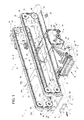
Figure 1 shows a perspective view, with parts removed for clarity, of a preferred embodiment of the wrapping unit according to the present invention; -
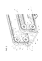
Figure 2 shows a larger-scale perspective view of a detail inFigure 1 ; -
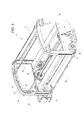
Figure 3 shows a larger-scale perspective view of a further detail inFigure 1 ; and -
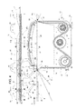
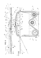
Figures 4 to 9 show larger-scale side views of a detail of the wrapping unit according to the present invention in different operating configurations. -
Figure 1 shows a product wrapping unit, designated as a whole by reference numeral 1, in apackaging line 2. - In particular, in the example shown, the products are defined by multi-packets 3, each comprising a given number, three in the specific case, of individual packets 4, which are arranged next to one another in a compact arrangement and are preferably defined by respective aseptic packets of a pourable food product, such as fruit juice, milk, wine, etc.
- For manufacturing packets 4 of this type,
packaging line 2 comprises, in known manner: - a forming unit (not shown), in which packets 4 are formed from flat pre-cut blanks or from a continuous strip of material;
- a filling unit (not shown);
- a packet grouping and alignment unit (not shown), in which packets 4 are grouped and ordered to form relative multi-packets 3; and
- a wrapping unit, in which multi-packets 3 are wrapped with a
film 5 of heat-shrinkable material. - As shown in
Figure 1 , according to the present invention, wrapping unit 1 comprises a conveyor 6 (a linear conveyor in the embodiment shown) for continuously feeding, in anadvancement direction 7, a succession ofrows 8 of multi-packets 3 through a wrapping station 9, in whichfilm 5 of heat-shrinkable material is wrapped around multi-packets 3. - The wrapping unit 1 further comprises an
oven 10, which receives multi-packets 3 from wrapping station 9 and is provided with heating means (not shown) forheating film 5 wrapped around multi-packets 3 to form respective wrappings.Rows 8 are uniformly spaced apart alongconveyor 6 and contain, each, one or more, two in the example shown, multi-packets 3 spaced from, and aligned with, one another in a direction 11 perpendicular toadvancement direction 7. - Wrapping unit 1 comprises, finally, a
stability control group 12, which will be described in detail hereinafter, and the function of which is to hinder a possible disequilibrium of packets 4 during advancement alongconveyor 6, and, in particular, at wrapping station 9, so that each packet 4 maintains its upright position and stays aligned to packets 4 of the respective multi-packet 3 and respective of other multi-packets 3 arranged in thesame row 8. - As shown in
Figures 1 and3 , wrapping station 9 comprises awrapping device 13 of known type and afilm feeding device 14, also of known type, which is arranged belowconveyor 6 and before wrappingdevice 13 with respect toadvancement direction 7 for feeding, during operation,film 5 cut into sheets to wrappingdevice 13. -
Wrapping device 13 comprises (Figure 3 ) a plurality ofbars 15, which are parallel to each other and to direction 11 and are mounted on a frame comprising twosupport plates 16 to move all together along an annular path A comprising a work stretch A1 arranged aboveconveyor 6 and a return stretch disposed belowconveyor 6. - In particular,
support plates 16 are arranged on opposite sides and outside ofconveyor 6, lie in respective vertical planes parallel toadvancement direction 7. On the inner side facing theother plate 16, eachsupport plate 16 carries arespective chain 17, which is looped around adriving pulley 18, is tensioned by a pair of tensioningpinions 19 arranged, as well as drivingpulley 18, belowconveyor 6 and engages in sliding manner agrooved guide 20 rigidly connected to a portion ofrespective plate 16 protruding aboveconveyor 6. - The
chain 17 may be replaced by another transmission element, for example a toothed belt. - In particular,
grooved guide 20 comprises anintermediate portion 21 that extends in a direction substantially parallel toadvancement direction 7 and defines, as it will be clear from what follows, the cited work stretch A1.Intermediate portion 21 is connected to the portion ofchain 17 looped around drivingpulley 18 and tensioningpinions 19 by means of two vertical sections ofchain 17, which are arranged, as clearly shown inFigures 4 to 9 , at respective transverse throughopenings 22 ofconveyor 6. - To this purpose,
conveyor 6 comprises afirst conveyor 23 disposed upstream from wrapping station 9, asecond conveyor 24 disposed downstream of wrapping station 9, and anintermediate conveyor 25, which is separate fromconveyors advancement direction 7 and define theaforementioned openings 22. - With reference to
Figure 3 , eachbar 15 extends from one to the other ofplates 16 perpendicularly toadvancement direction 7, and is rigidly connected tochains 17 by means of respective connecting elements fitted with respective ends ofbar 15. - During operation,
bars 15 are transported bychains 17 along path A so as to move always parallel to themselves and move along work stretch A1 inadvancement direction 7 and along the return stretch in the opposite direction toadvancement direction 7.Bars 15 move throughconveyor 6, in a direction transverse toadvancement direction 7 and to direction 11, at an inlet of the wrapping station 9, which inlet is defined by opening 22 arranged first inadvancement direction 7, and at an outlet of wrapping station 9, which outlet is defined by theother opening 22. In other words,bars 15 move I a substantially vertical directions at the inlet of the wrapping station 9 and at the outlet of the wrapping station 9, i.e. atopenings 22. - As will be described in more detail in the following,
bars 15intercept film 5 at the inlet of the wrapping station 9 and move with thefilm 5 along work stretch A1 at a speed higher than the speed of multi-packets 3 so as to wrapfilm 5 around multi-packets 3 and finally abandon wrapping station 9 at the outlet of the wrapping station 9. - As shown in
Figure 1 , the feeding device 14 (of known type) is adapted to receivefilm 5 of heat-shrinkable material in the form of a continuous strip unwound from a reel (not shown) and comprises, in series in a advancement direction R of the strip, a longitudinal cutter (not shown) adapted to cut the strip in the direction R to obtain two strips, a pair of opposite andcounter-rotating traction rollers 27, and atransverse cutter 28 adapted to cut the strips perpendicularly to direction R to obtain a succession of pairs ofsheets 29. -
Feeding device 14 also comprises a further pair of opposite andcounter-rotating traction rollers 30 adapted to advance in succession pairs ofsheets 29 on an aspiratedinclined plane 31, which cooperates with upper surface ofconveyor 25 at the inlet of the wrapping station 9 and is designed to guidesheets 29, launched through therelative opening 22, to the front edge ofintermediate conveyor 25. - With reference to
Figures 1 and2 ,stability control group 12 comprises aframe 32, on which a plurality of mobile anti-tip devices 33 (only two of which are illustrated infigure 1 ) are mounted, whose function is to prevent packets 4 of arespective row 8 from losing their equilibrium and falling forward or backward with respect toadvancement direction 7, before, during and after their advancement alongconveyor 25, and, in particular, at transition area betweenintermediate conveyor 25 andfirst conveyor 23 and at transition area betweenintermediate conveyor 25 andsecond conveyor 24, i.e. atopenings 22. -
Frame 32 is arranged entirely aboveconveyor 6 and comprises twoshoulders 34 rigidly connected to each other and defined by respective plates of generally rectangular shape, which lie on respective vertical planes parallel toadvancement direction 7 and are arranged on opposite sides ofconveyor 6. - Each
anti-tip device 33 preferably comprises a pair of rods 35, which are parallel to the plane ofconveyor 6 and perpendicular toadvancement direction 7, and are movable, parallel to themselves, along an annular path P comprising a work stretch PI, along which rods 35 advance alongconveyor 6 inadvancement direction 7 and at the same speed as multi-packets 3, and a return stretch, along which rods 35 are moved in the opposite direction toadvancement direction 7. - As will be clearly described in the following, along work stretch PI, each
anti-tip device 33 is associated with arespective row 8 and the corresponding rods 35 are arranged on opposite sides of thesame row 8, in respective positions facing to front and, respectively, rear faces of multi-packets 3 in thesame row 8. Therefore, for the sake of clarity, in the description that follows rods 35 of eachanti-tip device 33 will be indicated withreference numbers advancement direction 7 along the stretch work P1. - With reference to
Figures 4 to 9 , eachrod frame 32 to oscillate, when moving along work stretch PI, between a lowered or close position, in whichrod row 8 in such a way as to define a transverse stop member movable with thesame row 8, and a raised or spaced apart position, in whichrod row 8, and defines, withrow 8, arespective passage channel 36 adapted to permit, during operation, as will be explained in detail below, to abar 15 to move through advancement path ofrows 8 at the inlet of the wrapping station 9 and at the outlet of the wrapping station 9. - The
anti-tip device 33 are uniformly distributed along aforementioned path P, and are moved synchronously along path P by means of aconveying device 37, which is, in the example shown, a chain transport device, but could be replaced by any other synchronous transport device suitable for that purpose, for example a toothed belt.Rods 35aanti-tip device 33 are instead moved between the respective lowered position and raised position by means of acam device 38. - As illustrated in
Figures 1 and2 , each rod 35 is mounted toshoulders 34 offrame 32 by means of two fastening brackets arranged at ends of a respective rod 35 and defined byrespective rocker arms 39, each of which is pivoted, by means of arespective pin 40 parallel to rod 35, on arespective chain 41. - The
chain 41 may be replaced by another transmission element, for example a toothed belt. - Each
chain 41 is mounted to arespective shoulder 34, is looped around foursprockets 42, of which one is a powered sprocket, and includes a forward lower stretch, which is parallel toadvancement direction 7 and defines the aforementioned work stretch PI, and an rearward upper stretch, which is parallel to the lower stretch, defines the aforementioned return stretch and is connected to the lower stretch through two substantially vertical chain stretches. - Since each
anti-tip device 33 comprises tworods rocker arms 39,conveying device 37 includes fourtoothed chains 41, a first pair of which carries therocker arms 39 that are associated with therods 35a, and a second pair of which carries therocker arms 39 that are associated withrods 35b. Preferably, thetoothed chains 41 in the first pair are arranged facing one another on respective inner sides ofshoulders 34, while thetoothed chain 41 in the second pair are arranged on respective outer sides ofshoulders 34.Anti-tip devices 33 are uniformly distributed alongtoothed chains 41. - As shown in detail in
Figure 2 , eachrocker arm 39 comprises afirst arm 43, which extends up to and beyond the periphery of therespective shoulder 34, and has an end portion rigidly connected to one end of the respective rod 35, and asecond arm 44, which is fitted, at its free end, with afollower 45 engaging in transversely sliding manner atrack 46 of a respective annular front cam 47 which is integral with therelative shoulder 34. - Similarly to what said for
toothed chain 41,stability control group 12 comprises four frontal cams 47, which define, all together, theaforementioned cam device 38 and comprise a first pair offront cam 47a, which is associated withrocker arms 39 ofrods 35a, and a second pair offront cams 47b, which is associated to rockerarms 39 ofrods 35b. - In particular, each
front cam corresponding shoulder 34, and extends around therespective toothed chain 41. - As shown more clearly in
Figures 4 to 9 ,track 46 of eachfront cam 47b comprises a straight portion 48 parallel to work stretch PI and comprising acurved portion 50, which is arranged at the inlet of the wrapping station 9 and is shaped so as to cause, during operation, arocker arm 39 passing through it to swing around therespective pin 40 so as to moverelative rod 35b backward in an opposite direction toadvancement direction 7. - Similarly,
track 46 of eachface cam 47a includes a straight portion 48 parallel to work stretch PI and comprising acurved portion 49, which is arranged at an output of the wrapping station 9 and is shaped so as to cause, during operation, arocker arm 39 passing through it to swing around therespective pin 40 so as to move therespective rod 35a forward inadvancement direction 7. - With reference to the above, it is important to point out that, according to a variation not shown, each
anti-tip device 33 may comprise a single rod 35. In this embodiment, the remaining rod will act, depending on whether it is arod 35a or arod 35b, as transversal stop member for a corresponding front orrear row 8. Resultingly, in this embodiment,conveying device 37 comprises only one pair oftoothed chains 41, andcam device 38 only comprises a pair of front cams 47. - Finally, it should be specified that as previously described with respect to the stability control of two or more multi-packets 3 aligned along a
relative row 8 is clearly applicable, without any substantial modification, even for the stability control of a different product, for example a single packet. - The operation of the wrapping material 1 will be described in the following with reference to
Figures 4 to 9 , which show, by way of example, asingle row 8 advancing through the wrapping station 9. - As shown in
Figure 4 , when arow 8 is on the conveyor 23 (row 8 drawn with dotted line),rods anti-tip device 33 associated with thisrow 8 are both arranged in the lowered positions. Under the action of theconveyor 23,row 8 comes to an inlet of the wrapping station 9 (row 8 drawn with continuous line) and, through theopening 22, is advanced to theconveyor 25. Whenrow 8 passes ontoconveyor 25, the front edge of each multi-packet 3 engages the front end of arespective sheet 29, which remains gripped below themulti-packet 3 and is dragged forward alongconveyor 25. - Immediately before
row 8 passes through opening 22 at the inlet of the wrapping station 9,followers 45 ofrocker arms 39 which are fitted withrod 35b engage respectivecurved portions 50 of respectivefront cam 47b. As a result, asanti-tip device 33 advances inadvancement direction 7 together withrow 8,rocker arms 39 rotate around therespective pin 40 andspace rod 35b apart fromrow 8 in a direction opposite toadvancement direction 7, so as to allow thechannel 36 to be formed betweenrow 8 androd 35b and abar 15 to move upwards alongchannel 36. Whilerow 8 proceeds alongconveyor 25,bar 15 moves along portion A1 at a speed higher than that ofconveyor 25 and wraps (in known manner)sheets 29 of thefilm 5 around therespective multi-packets 3. - As shown in
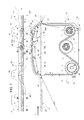
Figure 5 ,curved portion 50 is designed so that, as soon asbar 15 has passed throughopening 22, therelative rocker arms 39 rotate so as to bringrod 35b again in its lowered position, in whichrod 35b acts as a rear transversal barrier forrow 8. - As shown in
Figure 6 , movements ofrod 35b and bar 15 are timed to each other such that, whenrod 35b reaches its lowered position,bar 15 has wrappedsheets 29 around the rear face of therespective multi-packets 3 so that only a single layer offilm 5 remains betweenrod 35b and rear face ofmulti-packets 3. In this way,rod 35b is prevented to hold the portion ofsheet 29 still to be wound back against the action ofbar 15 so causing thesheet 29 to be pulled out from the bottom ofmulti-packets 3. - As shown in
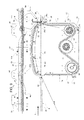
Figure 7 , beforerow 8 reaches the outlet of the wrapping station 9 and is transferred on theconveyor 24 through therelative opening 22,rocker arms 39 which are fitted withrod 35a behave in a similar way to what occurs torocker arms 39 fitted withrod 35b close to the inlet of the wrapping station 9. In fact, whenbar 15 gets close to the terminal portion of stretch A1,followers 45 ofrocker arms 39 fitted withrod 35a engage respectivecurved portions 49 and cause therespective rocker arms 39 to rotate with consequent spacing apart ofrod 35a fromrow 8 inadvancement direction 7 and formation ofchannel 36 betweenrod 35a and the front face ofmulti-packets 3. - The profile of
curved portion 49 is designed such thatrod 35a is substantially in its raised position when bar 15 passes throughaperture 22 and returns to the lowered position whenrow 8 has finally reached conveyor 24 (Figure 9 ). - From the foregoing it is possible to understand the advantages associated with wrapping unit 1 of the present invention and resulting from the presence of
stability control group 12 in combination with thefilm wrapping device 13. - In particular,
anti-tip devices 33 are able to support, if necessary,rows 8 before, during and after the wrapping station 9 by acting as fixed barriers without exerting any direct gripping thrust on packets 4 and, therefore, without the risk of damaging the packets 4. At the inlet of the wrapping station 9 and at the outlet of the wrapping station 9,anti-tip devices 33 are configured in such a way to effectively and quickly disengagerespective rows 8, especially in view of the considerable speeds at whichrow 8 are moved, and to the time strictly necessary to allow the passage ofbars 15 andfilm 5, while maintaining a partial supporting action ofmulti-packets 3 due to the presence of at least one amongrods
Claims (13)
- Wrapping unit (1) for a packaging line (2), comprising a conveyor (6) for feeding a succession of products (3) in a first direction (7) and a wrapping station (9) arranged along the conveyor (6) for wrapping a film (5) of wrapping material around said products (3), said wrapping station (9) comprising a wrapping device (13) provided with a plurality of wrapping members (15), each of said wrapping members (15) extending in a second direction (11) perpendicular to said first direction (7), said wrapping unit (1) being characterized by further comprising a stability control group (12) for preventing said products (3) from tipping along said conveyor (6), said stability control group (12) comprising a plurality of anti-tip devices (33), each of said anti-tip devices (33) being associated, during operation, with a respective product (3) to move together with said product (3) through said wrapping station (9).
- Wrapping unit according to claim 1, wherein each of said anti-tip devices (33) comprises at least one stop member (35), which extends in said second direction (11) and is operable to assume a close position, in which said stop member (35) is arranged close to and facing a front face or rear face of said product (3), and a spaced apart position, in which said stop member (35) is arranged at a determined distance from said product (3) and defines with said product (3) a passage (36) for a wrapping member (15).
- Wrapping unit according to claim 2, wherein said stop member (35) is arranged in said spaced apart position at an inlet of said wrapping station (9) and/or at an outlet of said wrapping station (9).
- Wrapping unit according to claim 2, or 3, wherein each anti-tip device (33) comprises a pair of said stop members (35a, 35b), which are adapted to be disposed on opposite sides of said respective product (3).
- Wrapping unit according to claim 4, wherein said stability control group (12) comprises a frame (32) and a conveying device (37) carried by said frame (32) to advance said anti-tip devices (33) along a predetermined path (P), said pair of stop members (35) of each anti-tip device (33) being operable independently from each other so that, when one of said stop members (35a, 35b) moves from said close position to said spaced apart position and vice versa, the other of said stop members (35b, 35a) remains in said close position.
- Wrapping unit according to claim 5, wherein said path (P) is an annular path comprising a straight work stretch (PI) extending parallel to said conveyor (6), said anti-tip devices (33) being movable along said work stretch (PI) at the same speed as said conveyor (6).
- Wrapping unit according to claim 5, or 6, wherein each pair of stop members (35a, 35b) comprises a rear stop member (35b) and a front stop member (35a), according to said first direction (7), said rear stop member (35b) being adapted to move from said close position to said spaced apart position at an inlet of said the wrapping station (9) and to remain in said spaced apart position for the time necessary to allow a wrapping member (15) to move, together with said film (5), through a corresponding passage (36) up to get above said rear stop member (35b), and said front stop member (35a) being adapted to move from said close position to said spaced apart position at an outlet of said wrapping station (9) and to remain in said spaced apart position for the time necessary to allow the wrapping member (15) to move, together with said film (5), through a corresponding passage (36) up to get below said front stop member (35a).
- Wrapping unit according to any one of claims 5 to 7, wherein said stability control group (12) comprises a cam device (38) carried by said frame (32) and coupled to each stop member (35) to move said stop member (35) from said close position to said spaced apart position and vice versa.
- Wrapping unit according to claim 8, as appended to claim 7, wherein said cam device (38) comprises a pair of first cams (47b) coupled to said rear stop members (35b) and a pair of second cams (47a) coupled to said front stop members (35a).
- Wrapping unit according to any one of claims 5 to 9, wherein each stop member (35) comprises a rod (35) that extends in said second direction (11) and is mounted to the conveying device (37) to move along said path (P) and oscillate between said close position and said spaced apart position around an axis (40) parallel to said second direction (11).
- Wrapping unit according to claim 10, as appended to claim 8, and further comprising, for each stop member (35), two rocker arms (39), each of which is fitted with a respective end of the relative rod (35) to couple said rod (35) with said conveying device (37) and said cam device (38), each rocker arm (39) being hinged to said conveying device (37) about said axis (40) and comprising a first arm (43) rigidly connected to said rod (35) and a second arm (44) that carries a follower (45) engaged with said cam device (38).
- Wrapping unit according to claim 11, wherein each follower (45) of each rear stop member (35b) engages in sliding manner a track (46) of a respective first cam (47b), and each follower (45) of each front stop member (35a) engages in sliding manner a track (46) of a respective second cam (47a).
- Wrapping unit according to any one of the preceding claims, wherein each wrapping member (15) is arranged to move, at an input of said wrapping station (9) and/or at an output of said wrapping station (9), in a third direction transverse to said first direction (7) and to said second direction (11).
Priority Applications (5)
| Application Number | Priority Date | Filing Date | Title |
|---|---|---|---|
| EP15157202.1A EP3064440B1 (en) | 2015-03-02 | 2015-03-02 | Product wrapping unit for a packaging line |
| US15/552,391 US10106280B2 (en) | 2015-03-02 | 2016-02-26 | Product wrapping unit for a packaging line |
| JP2017544344A JP6427685B2 (en) | 2015-03-02 | 2016-02-26 | Product Wrapping Unit for Packaging Line |
| PCT/EP2016/054068 WO2016139139A1 (en) | 2015-03-02 | 2016-02-26 | Product wrapping unit for a packaging line |
| CN201680011233.9A CN107249986B (en) | 2015-03-02 | 2016-02-26 | The product encapsulation unit of baling line |
Applications Claiming Priority (1)
| Application Number | Priority Date | Filing Date | Title |
|---|---|---|---|
| EP15157202.1A EP3064440B1 (en) | 2015-03-02 | 2015-03-02 | Product wrapping unit for a packaging line |
Publications (2)
| Publication Number | Publication Date |
|---|---|
| EP3064440A1 true EP3064440A1 (en) | 2016-09-07 |
| EP3064440B1 EP3064440B1 (en) | 2017-09-13 |
Family
ID=52595191
Family Applications (1)
| Application Number | Title | Priority Date | Filing Date |
|---|---|---|---|
| EP15157202.1A Active EP3064440B1 (en) | 2015-03-02 | 2015-03-02 | Product wrapping unit for a packaging line |
Country Status (5)
| Country | Link |
|---|---|
| US (1) | US10106280B2 (en) |
| EP (1) | EP3064440B1 (en) |
| JP (1) | JP6427685B2 (en) |
| CN (1) | CN107249986B (en) |
| WO (1) | WO2016139139A1 (en) |
Cited By (1)
| Publication number | Priority date | Publication date | Assignee | Title |
|---|---|---|---|---|
| EP3552995A3 (en) * | 2018-04-10 | 2019-11-20 | Krones Aktiengesellschaft | Work module for a packaging device and method for handling items and/or packaging material |
Families Citing this family (4)
| Publication number | Priority date | Publication date | Assignee | Title |
|---|---|---|---|---|
| US11878828B2 (en) * | 2018-05-11 | 2024-01-23 | Tetra Laval Holdings & Finance S.A. | Outfeed device for a packaging assembly and packaging assembly comprising an outfeed device |
| CN109850241A (en) * | 2018-08-07 | 2019-06-07 | 安徽御流包装机械有限公司 | The pushing hands equipment and paper diaper packing machine of paper diaper packing machine |
| CN109229675A (en) * | 2018-09-28 | 2019-01-18 | 杭州西奥电梯有限公司 | It is a kind of enclose side cut membranous system |
| WO2021086287A2 (en) * | 2019-10-28 | 2021-05-06 | Tufekciogullari Makine Gida Imalat Sanayi Ve Ticaret Limited Sirketi | A conveyance system for food packaging machines |
Citations (3)
| Publication number | Priority date | Publication date | Assignee | Title |
|---|---|---|---|---|
| FR2099261A5 (en) * | 1970-06-22 | 1972-03-10 | Ganz Robert | |
| EP0049377A1 (en) * | 1978-03-31 | 1982-04-14 | Ganz Brothers Inc. | Apparatus for supplying circular cross-section articles in longitudinally moving rows in a packaging apparatus |
| FR2688470A1 (en) * | 1992-03-11 | 1993-09-17 | Kisters Maschinenbau Gmbh | Method and device for packaging objects in a continuous process |
Family Cites Families (10)
| Publication number | Priority date | Publication date | Assignee | Title |
|---|---|---|---|---|
| DE2000023C3 (en) * | 1970-01-02 | 1975-03-20 | Benz & Hilgers Gmbh, 4000 Duesseldorf | Device for wrapping disc-shaped food and luxury items, such as cheese slices, chocolate bars and the like |
| JPH0759404B2 (en) * | 1989-12-05 | 1995-06-28 | 株式会社ニッサンキコー | Binding wrapping machine |
| US5626002A (en) * | 1995-12-11 | 1997-05-06 | Riverwood International Corporation | Packaging machine having overhead assembly for opening and lowering carton onto article groups |
| DE19847433A1 (en) * | 1998-10-15 | 2000-04-20 | Focke & Co | Device for generating reciprocating movements |
| US7533768B2 (en) * | 2002-03-27 | 2009-05-19 | Douglas Machine, Inc. | Retractable transfer device metering apparatus and methods |
| IT1392527B1 (en) * | 2008-12-24 | 2012-03-09 | A C M I Societa Per Azioni | SUPPLY UNIT FOR COIL PACKAGING RIBBONS, WITH AUTOMATIC CHANGE OF THE FEEDING ROLL, FOR MACHINES TO PACK ITEMS |
| JP5194139B2 (en) * | 2011-03-04 | 2013-05-08 | 三菱重工食品包装機械株式会社 | Packaging device using film |
| MX342420B (en) * | 2011-08-19 | 2016-09-28 | Graphic Packaging Int Inc | Apparatus and method for forming a carton. |
| CN204056343U (en) * | 2014-08-22 | 2014-12-31 | 慈溪太平鸟物流有限公司 | A kind of packing chest automatic packaging system |
| US20170361956A1 (en) * | 2015-01-15 | 2017-12-21 | Aetna Group S.P.A. | Apparatus for wrapping products with film |
-
2015
- 2015-03-02 EP EP15157202.1A patent/EP3064440B1/en active Active
-
2016
- 2016-02-26 JP JP2017544344A patent/JP6427685B2/en active Active
- 2016-02-26 CN CN201680011233.9A patent/CN107249986B/en active Active
- 2016-02-26 US US15/552,391 patent/US10106280B2/en active Active
- 2016-02-26 WO PCT/EP2016/054068 patent/WO2016139139A1/en active Application Filing
Patent Citations (3)
| Publication number | Priority date | Publication date | Assignee | Title |
|---|---|---|---|---|
| FR2099261A5 (en) * | 1970-06-22 | 1972-03-10 | Ganz Robert | |
| EP0049377A1 (en) * | 1978-03-31 | 1982-04-14 | Ganz Brothers Inc. | Apparatus for supplying circular cross-section articles in longitudinally moving rows in a packaging apparatus |
| FR2688470A1 (en) * | 1992-03-11 | 1993-09-17 | Kisters Maschinenbau Gmbh | Method and device for packaging objects in a continuous process |
Cited By (1)
| Publication number | Priority date | Publication date | Assignee | Title |
|---|---|---|---|---|
| EP3552995A3 (en) * | 2018-04-10 | 2019-11-20 | Krones Aktiengesellschaft | Work module for a packaging device and method for handling items and/or packaging material |
Also Published As
| Publication number | Publication date |
|---|---|
| US20180022487A1 (en) | 2018-01-25 |
| WO2016139139A1 (en) | 2016-09-09 |
| JP6427685B2 (en) | 2018-11-21 |
| US10106280B2 (en) | 2018-10-23 |
| JP2018507145A (en) | 2018-03-15 |
| CN107249986A (en) | 2017-10-13 |
| EP3064440B1 (en) | 2017-09-13 |
| CN107249986B (en) | 2018-10-12 |
Similar Documents
| Publication | Publication Date | Title |
|---|---|---|
| US10106280B2 (en) | Product wrapping unit for a packaging line | |
| US3894627A (en) | Conveyor for interspacing articles | |
| EP3106397B1 (en) | Package grouping unit with package linear speed reduction | |
| US3908333A (en) | Device for registering articles and package elements therefor during feed to a packaging machine | |
| EP2586718B1 (en) | Folding unit for producing folded packages of pourable food products from relative sealed packs | |
| US6964147B2 (en) | Operating method for a packaging machine of the “sleeve” type, packaging machine for implementing the said method, and package produced by the said method | |
| US5341913A (en) | Device for forming piles of articles, particularly for automatic packaging plants | |
| WO2016202558A1 (en) | Package grouping unit with package linear speed reduction | |
| ITBO990585A1 (en) | MACHINE FOR ORDERING AND FEEDING STACKS OF SHEETS TO A UNIT OF STACKING GROUPS. | |
| US4854108A (en) | Automatic wrapping machine | |
| EP0004744B1 (en) | Apparatus for forming packages | |
| EP3245135B1 (en) | Apparatus for wrapping with a film | |
| WO2014147422A1 (en) | Apparatus to feed a collation of deformable packets to a form/fill/seal machine | |
| WO2020174504A1 (en) | System and operating method for packaging paper rolls. | |
| CN110139818B (en) | Method and device for stacking products | |
| US7726462B2 (en) | Method and unit for the formation of groups of products in a machine for continuous packaging of products | |
| EP3566960A1 (en) | Folding unit for a packaging assembly and packaging assembly comprising a folding unit | |
| WO2018089727A1 (en) | Device and method for distributing products conveyed in succession | |
| WO2009150034A1 (en) | Station for receiving products and temporarily accommodating them | |
| JPH0676083B2 (en) | Horizontal bag-making filling and packaging machine | |
| JP2004299709A (en) | Packaging apparatus |
Legal Events
| Date | Code | Title | Description |
|---|---|---|---|
| PUAI | Public reference made under article 153(3) epc to a published international application that has entered the european phase |
Free format text: ORIGINAL CODE: 0009012 |
|
| AK | Designated contracting states |
Kind code of ref document: A1 Designated state(s): AL AT BE BG CH CY CZ DE DK EE ES FI FR GB GR HR HU IE IS IT LI LT LU LV MC MK MT NL NO PL PT RO RS SE SI SK SM TR |
|
| AX | Request for extension of the european patent |
Extension state: BA ME |
|
| 17P | Request for examination filed |
Effective date: 20170307 |
|
| RBV | Designated contracting states (corrected) |
Designated state(s): AL AT BE BG CH CY CZ DE DK EE ES FI FR GB GR HR HU IE IS IT LI LT LU LV MC MK MT NL NO PL PT RO RS SE SI SK SM TR |
|
| GRAP | Despatch of communication of intention to grant a patent |
Free format text: ORIGINAL CODE: EPIDOSNIGR1 |
|
| INTG | Intention to grant announced |
Effective date: 20170529 |
|
| GRAS | Grant fee paid |
Free format text: ORIGINAL CODE: EPIDOSNIGR3 |
|
| GRAA | (expected) grant |
Free format text: ORIGINAL CODE: 0009210 |
|
| AK | Designated contracting states |
Kind code of ref document: B1 Designated state(s): AL AT BE BG CH CY CZ DE DK EE ES FI FR GB GR HR HU IE IS IT LI LT LU LV MC MK MT NL NO PL PT RO RS SE SI SK SM TR |
|
| REG | Reference to a national code |
Ref country code: GB Ref legal event code: FG4D |
|
| REG | Reference to a national code |
Ref country code: CH Ref legal event code: EP |
|
| REG | Reference to a national code |
Ref country code: IE Ref legal event code: FG4D |
|
| REG | Reference to a national code |
Ref country code: AT Ref legal event code: REF Ref document number: 927866 Country of ref document: AT Kind code of ref document: T Effective date: 20171015 |
|
| REG | Reference to a national code |
Ref country code: DE Ref legal event code: R096 Ref document number: 602015004549 Country of ref document: DE |
|
| REG | Reference to a national code |
Ref country code: FR Ref legal event code: PLFP Year of fee payment: 4 |
|
| REG | Reference to a national code |
Ref country code: NL Ref legal event code: MP Effective date: 20170913 |
|
| REG | Reference to a national code |
Ref country code: LT Ref legal event code: MG4D |
|
| PG25 | Lapsed in a contracting state [announced via postgrant information from national office to epo] |
Ref country code: FI Free format text: LAPSE BECAUSE OF FAILURE TO SUBMIT A TRANSLATION OF THE DESCRIPTION OR TO PAY THE FEE WITHIN THE PRESCRIBED TIME-LIMIT Effective date: 20170913 Ref country code: LT Free format text: LAPSE BECAUSE OF FAILURE TO SUBMIT A TRANSLATION OF THE DESCRIPTION OR TO PAY THE FEE WITHIN THE PRESCRIBED TIME-LIMIT Effective date: 20170913 Ref country code: HR Free format text: LAPSE BECAUSE OF FAILURE TO SUBMIT A TRANSLATION OF THE DESCRIPTION OR TO PAY THE FEE WITHIN THE PRESCRIBED TIME-LIMIT Effective date: 20170913 Ref country code: NO Free format text: LAPSE BECAUSE OF FAILURE TO SUBMIT A TRANSLATION OF THE DESCRIPTION OR TO PAY THE FEE WITHIN THE PRESCRIBED TIME-LIMIT Effective date: 20171213 Ref country code: SE Free format text: LAPSE BECAUSE OF FAILURE TO SUBMIT A TRANSLATION OF THE DESCRIPTION OR TO PAY THE FEE WITHIN THE PRESCRIBED TIME-LIMIT Effective date: 20170913 |
|
| REG | Reference to a national code |
Ref country code: AT Ref legal event code: MK05 Ref document number: 927866 Country of ref document: AT Kind code of ref document: T Effective date: 20170913 |
|
| PG25 | Lapsed in a contracting state [announced via postgrant information from national office to epo] |
Ref country code: ES Free format text: LAPSE BECAUSE OF FAILURE TO SUBMIT A TRANSLATION OF THE DESCRIPTION OR TO PAY THE FEE WITHIN THE PRESCRIBED TIME-LIMIT Effective date: 20170913 Ref country code: BG Free format text: LAPSE BECAUSE OF FAILURE TO SUBMIT A TRANSLATION OF THE DESCRIPTION OR TO PAY THE FEE WITHIN THE PRESCRIBED TIME-LIMIT Effective date: 20171213 Ref country code: GR Free format text: LAPSE BECAUSE OF FAILURE TO SUBMIT A TRANSLATION OF THE DESCRIPTION OR TO PAY THE FEE WITHIN THE PRESCRIBED TIME-LIMIT Effective date: 20171214 Ref country code: LV Free format text: LAPSE BECAUSE OF FAILURE TO SUBMIT A TRANSLATION OF THE DESCRIPTION OR TO PAY THE FEE WITHIN THE PRESCRIBED TIME-LIMIT Effective date: 20170913 Ref country code: RS Free format text: LAPSE BECAUSE OF FAILURE TO SUBMIT A TRANSLATION OF THE DESCRIPTION OR TO PAY THE FEE WITHIN THE PRESCRIBED TIME-LIMIT Effective date: 20170913 |
|
| PG25 | Lapsed in a contracting state [announced via postgrant information from national office to epo] |
Ref country code: NL Free format text: LAPSE BECAUSE OF FAILURE TO SUBMIT A TRANSLATION OF THE DESCRIPTION OR TO PAY THE FEE WITHIN THE PRESCRIBED TIME-LIMIT Effective date: 20170913 |
|
| PG25 | Lapsed in a contracting state [announced via postgrant information from national office to epo] |
Ref country code: CZ Free format text: LAPSE BECAUSE OF FAILURE TO SUBMIT A TRANSLATION OF THE DESCRIPTION OR TO PAY THE FEE WITHIN THE PRESCRIBED TIME-LIMIT Effective date: 20170913 Ref country code: PL Free format text: LAPSE BECAUSE OF FAILURE TO SUBMIT A TRANSLATION OF THE DESCRIPTION OR TO PAY THE FEE WITHIN THE PRESCRIBED TIME-LIMIT Effective date: 20170913 Ref country code: RO Free format text: LAPSE BECAUSE OF FAILURE TO SUBMIT A TRANSLATION OF THE DESCRIPTION OR TO PAY THE FEE WITHIN THE PRESCRIBED TIME-LIMIT Effective date: 20170913 |
|
| PG25 | Lapsed in a contracting state [announced via postgrant information from national office to epo] |
Ref country code: SK Free format text: LAPSE BECAUSE OF FAILURE TO SUBMIT A TRANSLATION OF THE DESCRIPTION OR TO PAY THE FEE WITHIN THE PRESCRIBED TIME-LIMIT Effective date: 20170913 Ref country code: AT Free format text: LAPSE BECAUSE OF FAILURE TO SUBMIT A TRANSLATION OF THE DESCRIPTION OR TO PAY THE FEE WITHIN THE PRESCRIBED TIME-LIMIT Effective date: 20170913 Ref country code: IS Free format text: LAPSE BECAUSE OF FAILURE TO SUBMIT A TRANSLATION OF THE DESCRIPTION OR TO PAY THE FEE WITHIN THE PRESCRIBED TIME-LIMIT Effective date: 20180113 Ref country code: SM Free format text: LAPSE BECAUSE OF FAILURE TO SUBMIT A TRANSLATION OF THE DESCRIPTION OR TO PAY THE FEE WITHIN THE PRESCRIBED TIME-LIMIT Effective date: 20170913 Ref country code: EE Free format text: LAPSE BECAUSE OF FAILURE TO SUBMIT A TRANSLATION OF THE DESCRIPTION OR TO PAY THE FEE WITHIN THE PRESCRIBED TIME-LIMIT Effective date: 20170913 |
|
| REG | Reference to a national code |
Ref country code: DE Ref legal event code: R097 Ref document number: 602015004549 Country of ref document: DE |
|
| PLBE | No opposition filed within time limit |
Free format text: ORIGINAL CODE: 0009261 |
|
| STAA | Information on the status of an ep patent application or granted ep patent |
Free format text: STATUS: NO OPPOSITION FILED WITHIN TIME LIMIT |
|
| PG25 | Lapsed in a contracting state [announced via postgrant information from national office to epo] |
Ref country code: DK Free format text: LAPSE BECAUSE OF FAILURE TO SUBMIT A TRANSLATION OF THE DESCRIPTION OR TO PAY THE FEE WITHIN THE PRESCRIBED TIME-LIMIT Effective date: 20170913 |
|
| 26N | No opposition filed |
Effective date: 20180614 |
|
| REG | Reference to a national code |
Ref country code: CH Ref legal event code: PL |
|
| PG25 | Lapsed in a contracting state [announced via postgrant information from national office to epo] |
Ref country code: MC Free format text: LAPSE BECAUSE OF FAILURE TO SUBMIT A TRANSLATION OF THE DESCRIPTION OR TO PAY THE FEE WITHIN THE PRESCRIBED TIME-LIMIT Effective date: 20170913 Ref country code: SI Free format text: LAPSE BECAUSE OF FAILURE TO SUBMIT A TRANSLATION OF THE DESCRIPTION OR TO PAY THE FEE WITHIN THE PRESCRIBED TIME-LIMIT Effective date: 20170913 |
|
| REG | Reference to a national code |
Ref country code: BE Ref legal event code: MM Effective date: 20180331 |
|
| REG | Reference to a national code |
Ref country code: IE Ref legal event code: MM4A |
|
| PG25 | Lapsed in a contracting state [announced via postgrant information from national office to epo] |
Ref country code: LU Free format text: LAPSE BECAUSE OF NON-PAYMENT OF DUE FEES Effective date: 20180302 |
|
| PG25 | Lapsed in a contracting state [announced via postgrant information from national office to epo] |
Ref country code: IE Free format text: LAPSE BECAUSE OF NON-PAYMENT OF DUE FEES Effective date: 20180302 |
|
| PG25 | Lapsed in a contracting state [announced via postgrant information from national office to epo] |
Ref country code: CH Free format text: LAPSE BECAUSE OF NON-PAYMENT OF DUE FEES Effective date: 20180331 Ref country code: LI Free format text: LAPSE BECAUSE OF NON-PAYMENT OF DUE FEES Effective date: 20180331 Ref country code: BE Free format text: LAPSE BECAUSE OF NON-PAYMENT OF DUE FEES Effective date: 20180331 |
|
| PGFP | Annual fee paid to national office [announced via postgrant information from national office to epo] |
Ref country code: CH Payment date: 20181015 Year of fee payment: 7 |
|
| GBPC | Gb: european patent ceased through non-payment of renewal fee |
Effective date: 20190302 |
|
| PG25 | Lapsed in a contracting state [announced via postgrant information from national office to epo] |
Ref country code: MT Free format text: LAPSE BECAUSE OF NON-PAYMENT OF DUE FEES Effective date: 20180302 Ref country code: GB Free format text: LAPSE BECAUSE OF NON-PAYMENT OF DUE FEES Effective date: 20190302 |
|
| PG25 | Lapsed in a contracting state [announced via postgrant information from national office to epo] |
Ref country code: TR Free format text: LAPSE BECAUSE OF FAILURE TO SUBMIT A TRANSLATION OF THE DESCRIPTION OR TO PAY THE FEE WITHIN THE PRESCRIBED TIME-LIMIT Effective date: 20170913 |
|
| PG25 | Lapsed in a contracting state [announced via postgrant information from national office to epo] |
Ref country code: PT Free format text: LAPSE BECAUSE OF FAILURE TO SUBMIT A TRANSLATION OF THE DESCRIPTION OR TO PAY THE FEE WITHIN THE PRESCRIBED TIME-LIMIT Effective date: 20170913 |
|
| PG25 | Lapsed in a contracting state [announced via postgrant information from national office to epo] |
Ref country code: CY Free format text: LAPSE BECAUSE OF FAILURE TO SUBMIT A TRANSLATION OF THE DESCRIPTION OR TO PAY THE FEE WITHIN THE PRESCRIBED TIME-LIMIT Effective date: 20170913 Ref country code: MK Free format text: LAPSE BECAUSE OF NON-PAYMENT OF DUE FEES Effective date: 20170913 Ref country code: HU Free format text: LAPSE BECAUSE OF FAILURE TO SUBMIT A TRANSLATION OF THE DESCRIPTION OR TO PAY THE FEE WITHIN THE PRESCRIBED TIME-LIMIT; INVALID AB INITIO Effective date: 20150302 |
|
| PG25 | Lapsed in a contracting state [announced via postgrant information from national office to epo] |
Ref country code: AL Free format text: LAPSE BECAUSE OF FAILURE TO SUBMIT A TRANSLATION OF THE DESCRIPTION OR TO PAY THE FEE WITHIN THE PRESCRIBED TIME-LIMIT Effective date: 20170913 |
|
| PG25 | Lapsed in a contracting state [announced via postgrant information from national office to epo] |
Ref country code: FR Free format text: LAPSE BECAUSE OF NON-PAYMENT OF DUE FEES Effective date: 20200331 |
|
| PGFP | Annual fee paid to national office [announced via postgrant information from national office to epo] |
Ref country code: IT Payment date: 20230321 Year of fee payment: 9 Ref country code: DE Payment date: 20230328 Year of fee payment: 9 |
|
| P01 | Opt-out of the competence of the unified patent court (upc) registered |
Effective date: 20230426 |