EP3064111B1 - Method for mounting a shower tray - Google Patents
Method for mounting a shower tray Download PDFInfo
- Publication number
- EP3064111B1 EP3064111B1 EP15290061.9A EP15290061A EP3064111B1 EP 3064111 B1 EP3064111 B1 EP 3064111B1 EP 15290061 A EP15290061 A EP 15290061A EP 3064111 B1 EP3064111 B1 EP 3064111B1
- Authority
- EP
- European Patent Office
- Prior art keywords
- shower tray
- mounting structure
- wedge shaped
- upper portion
- bottom portion
- Prior art date
- Legal status (The legal status is an assumption and is not a legal conclusion. Google has not performed a legal analysis and makes no representation as to the accuracy of the status listed.)
- Active
Links
- 238000000034 method Methods 0.000 title claims description 19
- 230000000284 resting effect Effects 0.000 claims description 7
- 238000009434 installation Methods 0.000 description 5
- 239000000463 material Substances 0.000 description 3
- 239000000919 ceramic Substances 0.000 description 2
- 244000298643 Cassia fistula Species 0.000 description 1
- 230000009286 beneficial effect Effects 0.000 description 1
- 238000010276 construction Methods 0.000 description 1
- 230000007812 deficiency Effects 0.000 description 1
- 238000005516 engineering process Methods 0.000 description 1
- 238000003780 insertion Methods 0.000 description 1
- 230000037431 insertion Effects 0.000 description 1
- 230000035939 shock Effects 0.000 description 1
- XLYOFNOQVPJJNP-UHFFFAOYSA-N water Substances O XLYOFNOQVPJJNP-UHFFFAOYSA-N 0.000 description 1
Images


Classifications
-
- A—HUMAN NECESSITIES
- A47—FURNITURE; DOMESTIC ARTICLES OR APPLIANCES; COFFEE MILLS; SPICE MILLS; SUCTION CLEANERS IN GENERAL
- A47K—SANITARY EQUIPMENT NOT OTHERWISE PROVIDED FOR; TOILET ACCESSORIES
- A47K3/00—Baths; Douches; Appurtenances therefor
- A47K3/16—Devices for fastening baths to floors or walls; Adjustable bath feet ; Lining panels or attachments therefor
Definitions
- the present invention relates to a method for mounting a shower tray, and a support assembly for supporting a shower tray during such mounting.
- a solution to this problem may be to have two persons installing the tray. Even though the load on each person is reduced, it is still very hard to adjust the location of the tray. Further to this, since shower trays are often installed in a bathroom corner it is not beneficial to have two persons working on the same side, or adjacent sides of the relatively small shower tray.
- German utility model DE 20 2009 003 052 U1 discloses a support structure for a shower tub.
- the present invention preferably seeks to mitigate or eliminate one or more of the above-identified deficiencies in the art singly or in any combination and solves at least the above mentioned problems.
- a method for mounting a shower tray comprises a step of arranging a plurality of shower tray supports on the floor or on the shower tray.
- the method further comprises the following steps: Arranging at least one temporary mounting structure on the floor at a position within and adjacent a boundary of an area, at which the shower tray is to be positioned in use, wherein the height of the temporary mounting structure is less than the height of the shower tray supports; wherein the mounting structure comprises a bottom portion having a planar structure for resting on a floor, and an upper portion having a planar structure for supporting a shower tray, wherein the mounting structure further comprises means for adjusting the distance between the planar structure of the bottom portion and the planar structure of the upper portion, wherein the bottom portion and the upper portion are wedge shaped members, each of the wedge shaped members being provided with a top surface, the top surfaces are connectable to each other thus forming the means for adjusting the distance between the planar structure of the bottom portion and the planar structure of the upper portion, wherein each one of the upper portion and the bottom portion forms a hollow cavity configured to receive a corner of a shower tray, positioning the shower tray onto the shower tray supports and the floor, tilt
- the method may further comprise the step of securing each one of the shower tray supports at a fixed position of the floor.
- a mounting structure for use as a temporary mounting structure in the method according to first aspect.
- the mounting structure comprises a bottom portion having a planar structure for resting on a floor, and an upper portion having a planar structure for supporting a shower tray, wherein the mounting structure further comprises means for adjusting the distance between the planar structure of the bottom portion and the planar structure of the upper portion.
- the bottom portion and the upper portion are wedge shaped members, each of the wedge shaped members being provided with a top surface, the top surfaces are connectable to each other thus forming the means for adjusting the distance between the planar structure of the bottom portion and the planar structure of the upper portion, and wherein each one of the upper portion and the bottom portion forms a hollow cavity configured to receive a corner of a shower tray.
- the mounting structure may further comprise means for preventing longitudinal sliding between the two wedge shaped members when the two top surfaces are connected to each other.
- Each top surface may be provided with a plurality of laterally distributed gripping ribs, wherein the gripping ribs form part of the means for preventing sliding between the two wedge shaped members.
- the means for adjusting the distance between the bottom portion and the upper portion further comprises a locking pin, insertable through a symmetrically arranged elongated hole in each of the top surfaces and configured to lock the two wedge shaped members together when the two top surfaces are connected to each other.
- each wedge shaped member further comprises a locking hinge provided at a side wall of the wedge shaped member adjacent to the top surface thereof, and a rail arranged on at least a part of the side wall and extending essentially parallel with the top surface at a distance thereof, wherein the distance is arranged such that the locking hinge of one wedge shaped member is arranged to engage the rail of the other wedge shaped member when the two top surfaces of the wedge shaped members are connected.
- the mounting structure may further comprise a number of flexible inner flanges extending into the cavity, whereby the inner flanges act to engage with and hold the corner section of the shower tray in place in the inner cavity during transport.
- At least one of the bottom portion and upper portion may further comprise screw holes for allowing a rigid attachment of the mounting structure to the floor in a shower area by means of an attachment screw or similar.
- the mounting structure may be used as a package support for protecting the corners of a shower tray during transport and storage , wherein the hollow cavity of the wedge shaped members is configured to receive a corner of a shower tray.
- An idea of the present invention is to provide an improved method for mounting a shower tray, as well as a mounting structure for supporting a heavy shower tray that allows the installer to easily position the shower tray, but also to adjust the height and leveling of the tray after it has been placed a first time. Furthermore, the present invention simplifies installation of ceramic shower trays in bathrooms with U-shaped shower areas. In addition, the mounting structure described herein may be used for protecting the corner edges of the shower tray during transportation and storage in a cost-effective way.
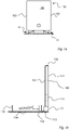
- a shower tray 100 located in a shower area of a bathroom is shown during mounting and installation.
- This shower tray 100 has a rectangular shape, although any shape is possible, and comprises a top surface 101, a bottom surface 102 and four side surfaces 103.
- the bottom surface 102 is facing the floor or foundation 104 and the top surface 101 is facing up towards the shower compartment and a user.
- Two mounting structures 10 used as temporary supports during mounting and installation are located on the floor 104 in order to support the shower tray 100 temporarily during repositioning of the shower tray 100. If the shower tray 100 is to be positioned such that at least one of the side surfaces 103 is in close proximity with a wall, the mounting structures 10 are preferably arranged close to that wall.
- the shower tray 100 is first positioned onto several shower tray supports 110 as is shown in Fig. Id.
- the height of the shower tray supports 110 is preferably adjusted prior to installation such that the shower tray 100 has a horizontal position. In practice this is however very difficult and almost impossible due to irregularities in the floor, why repositioning is normally required by adjusting the height of the shower tray supports 110.
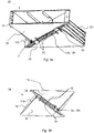
- the shower tray 100 is tilted upwards such that one of its side surfaces 103 is resting on the upper surface of each of the mounting structures 10 at least along one side of the shower tray 100. This is shown in Fig. 1b .
- the height of the shower tray supports 110 is adjusted.
- the shower tray 100 may then be tilted down from its vertical position, as is shown in Fig. 1c , to a horizontal position thereby resting on the shower tray supports 110. This position is as already mentioned shown in Fig. Id.
- the height of the mounting structures 10 is less than the height of the shower tray supports 110.
- the shower tray supports 110 can be of various types as long as they can carry the weight of the shower tray 100 and a person standing on the shower tray. Further, the height of the shower tray supports 110 is adjustable, and in one embodiment each shower tray support 110 includes means, such as screws or similar, for securely positioning the shower tray support 110 relative the floor.
- shower tray supports 110 could be securely positioned on the shower tray by means, e.g. screws or similar, instead of being securely positioned to the floor.
- a water drain 105 is schematically shown and a corresponding drain hole 106 in the shower tray 100 is also shown in Figs. 1b-1d .
- the geometry of the shower tray 100 may differ from that shown in Figs. 1a-d . It could have any shape, e.g. partly circular, square, triangular or any other regular or non-regular shape.
- the geometry of the shower tray 100 is only restricted by having at least one side surface 103 that could be placed on top of at least one mounting structure 10, and that an underside 102 of the shower tray 100 is allowed to rest on the shower tray supports 110 once the shower tray 100 has been tilted downwards.
- the shower tray 100 is shown, indicating the connection between the shower tray supports 110 and the shower tray 100.
- the shower tray supports 110 are adjustable in height, preferably but necessarily by two parts being connected by means of threads such that rotation of one part relative the other part adjusts the height.
- Four shower tray supports 110 are provided, each one being arranged at a corner area of the shower tray 100.
- a centrally aligned support 11 may also be provided to support the weight of a person standing on the shower tray 100.
- the shower tray supports 110 are attached to the shower tray 100, e.g. by allowing the upper ends of the shower tray supports 110 to be accommodated in recesses of the shower tray 100.
- the shower tray supports 110 could in an alternative embodiment be attached to or securely positioned on the floor of the area, e.g. shower compartment, at which the shower tray 100 is to be positioned in use.
- a combination of the two previously mentioned alternatives could be used, wherein at least one shower tray support 110 is attached to the floor and at least one shower tray support 110 is attached to the shower tray 100.
- Figs. 3a and 3b positioning of the shower tray 100 is shown. Installing a shower tray 100 in any of these positions greatly increases the need for the mounting structures 10 described herein.
- the shower tray 100 is installed in an area such that two complete sides of the shower tray 100 are in close proximity of walls, and a third side is at least partly in close proximity to a wall.
- the shower tray is installed in a corner of a room, such that two sides are in close proximity with walls.
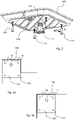
- the mounting structure 10 comprises two, preferably identical, wedge shaped members 11a, 11b, each having a tilted top surface 12a, 12b.
- the two top surfaces 12a, 12b are connected to each other they form the mounting structure 10, which due to the connection between the two members 11a, 11b is height adjustable.
- Each of the wedge shaped members 11a, 11b has a support surface 21, one being supporting the shower tray 100 in use and the other resting on the floor or foundation 104 in use.
- the support surface 21 may not necessarily be a large surface, but it may be formed by a frame structure leaving the wedge shaped members 11a, 11b substantially hollow.
- each of the top surfaces 12a, 12b comprises gripping ribs 13. These ribs 13 act to prevent the wedge shaped members 11a, 11b from sliding in a longitudinal direction relative to each other when the two top surfaces 12a, 12b are connected as shown.
- Fig. 4a shows a state where the mounting structure 10 is in, or near, its maximum top position, i.e. where wedge shaped members 11a, 11b are connected such that the maximum height between the two support surfaces 21 is achieved.
- the maximum height is between 120 and 250 mm, e.g. 165 mm.
- Fig. 4b shows a state where the mounting structure 10 is in its lowest position, i.e. in which the wedge shaped members 11a, 11b are connected such that the minimum height is achieved.
- the minimum height is between 70 and 140 mm, e.g. 95 mm.
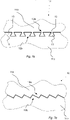
- the gripping ribs 13 of each of the top surfaces 12a, 12b extends laterally over each of the top surfaces 12a, 12b. Seen from the side the distribution of ribs 13 has a saw tooth shape. Two adjacent ribs 13, which may be seen as protrusions, together form a cavity there between. The cavity has an inverted shape of a rib 13, thereby allowing each cavity of one top surface 12a, 12b, to receive a rib 13 of the other top surface 12a, 12b. The lateral arrangement of the ribs and cavities when connected prevent the top surfaces from sliding relatively each other in the longitudinal direction when connected.
- Fig. 5 shows a wedge shaped member 11a, 11b according to an embodiment.
- a locking pin 14 is provided.
- the locking pin 14, which may be pre-attached to the wedge shaped member 11a, 11b, is detachable for locking the wedge shaped members 11a, 11b to each other.
- the locking pin 14 is insertable through symmetrically arranged elongated holes 15, arranged in each one of the top surfaces 12a, 12b, when they are to be connected.
- the locking pin 14 is arranged to lock the two wedge shaped members 11a, 11b together when the two top surfaces 12a, 12b are facing each other.
- the locking pin 14 may be provided with a lower flange 141 having an elongated shape with a width fitting through the elongated hole 15.
- a holding flange 142 arranged at an axial distance from the lower flange 141, and corresponding to the total thickness of the two top surfaces 12a, 12b has a shape and dimensions which does not allow it to pass through the elongated holes 15 of the two top surfaces 12a, 12b.
- a handle 143 may be rotated, thereby rotating the elongated portion of the lower flange 141 into a locked position in which it may not pass out of the elongated hole 15. In this way the holding flange 142 and the lower flange 141 securely locks the two top surfaces 12a, 12b together.
- the wedge shaped member 11a, 11b may comprise at least one screw hole 35 for allowing a rigid attachment of said wedge shaped member 11a, 11b to the foundation 104 in the shower area by means of an attachment screw or similar.
- This hole may be a straight through hole 35 or a hole forming an opening extending from an outer boundary of the support surface 21.
- each wedge shaped member 11a, 11b in addition to the top surface 12a, 12b comprises two opposing side walls 32 and a rear wall 34 together forming a hollow cavity 17 within the wedge shaped member 11a, 11b.
- At least one flexible inner rib 18 is extending from each side wall 32 towards the interior of each wedge shaped member 11a, 11b within the cavity 17.
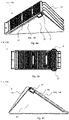
- the inner cavity 17 is arranged to receive a corner section of the shower tray as shown in Fig. 6 , whereby the inner ribs 18 act to engage with and hold the corner section of the shower tray 100 in place inside the inner cavity 17 during transport. Due to the flexibility of the inner flanges 18 a range of shower tray thicknesses may securely fit in the cavity 17.
- wedge shaped members 11a, 11b together form a package support for protecting the corners of a shower tray 100 during transport and storage.
- Each wedge shaped member 11a, 11b forms a hollow cavity 17 configured to receive a corner of a shower tray 100.
- the wedge shaped members 11a, 11b are further connectable to each other thus forming a mounting structure 10 for use as a temporary mounting structure in the method described above with reference to Figs. 1a-d .
- Figs. 7a-b show two different configurations of the gripping members 13 of the two top surfaces 12a, 12b according to an alterative embodiment.
- the gripping ribs 13 are chamfered and having an increasing width at increased distance from a base level of the top surface 12a, 12b.
- a corresponding chamfered cavity 16 is formed between each two adjacent chamfered gripping ribs 13 of one of the wedge shaped members 11a, 11b.
- the chamfered cavity 16 has a shape for receiving a chamfered gripping rib 13of the other top surface 12a, 12b.
- the gripping ribs 13 are saw tooth shaped. No locking in the height direction is achieved, but only in a direction being parallel with the slope angle of the top surfaces 12a, 12b.
- each of the wedge shaped members 11a, 11b further comprises a locking hinge 31 provided at a side wall 32 of the wedge shaped member 11a, 11b and adjacent to the top surface 12a, 12b thereof.
- a rail 33 is arranged on at least a part of the side wall 32 and extending essentially parallel with the top surface 12a, 12b at a distance thereof. The distance between the rail 33 and the top surface 12a, 12b is configured such that the locking hinge 31 of one wedge shaped member 11a, 11b can engage the rail 33 of the other wedge shaped member 11a, 11b when the two top surfaces 12a, 12b of the wedge shaped members 11a, 11b are connected.
- the locking hinge 31 may thus be used as an alternative locking solution to the locking pin 14 and the elongated hole 15 as shown in Fig. 5 .
- any symmetrically aligned longitudinally elongated hole 15 is not necessary for the purpose of locking the two wedge shaped members 11a, 11b together.
- Fig. 8a shows a perspective view of a wedge shaped member 11a, 11b having a locking hinge 31 and corresponding rail 33.
- Fig. 8b shows a bottom view of the wedge shaped member 11a, 11b of Fig. 8a
- Fig. 8c shows a side view of the same.
- Figs. 9a-c show two wedge shaped members 11a, 11b of Figs. 8a to 8c locked together using the locking hinges.
- Fig. 10a shows the locking hinge 31 more in further detail.
- a pivotable hinge flap 34 is shown.
- the hinge flap 34 is pivoted around a joint (not shown) in the locking hinge 31 and approximately 180° down over the rail 33, thereby providing a snap fit.
- Fig. 10b shows the rail 33 of a wedge shaped member 11a, 11b more in detail.
- the saw tooth shaped gripping ribs 13 are also shown in Fig. 10a-b .
- the rail 33 may have a receiving surface being chamfered for facilitating the reception of the hinge flap 34 upon connection between the two.
- an exterior part of the hinge flap 34 forming a hook like member, engages with this chamfered surface thereby making it easier for the exterior part of the hinge flap 34 to slide up an over the top of the chamfered surface.
- the exterior part of the hinge flap 34 i.e. the part thereof engaging with the rail, may have an inverted shape corresponding to the shape of the receiving surface to securely locking the hinge flap 34 to the rail 33.
- the receiving surface of the rail is not required to be chamfered.
- Exterior shock absorbing ribs 191 extending outwards from the side walls 32 and/or the rear wall, as shown in Figs. 9b may be provided such as to protect the shower tray corners during transport as shown in Fig. 6 , as well as to increase the robustness of the members 11a, 11b and also of the mounting structure 10.
- the wedge shaped members 11a, 11b are preferably made of a plastic material,
- the inner ribs may be made from the same material or another material being suitable for the purpose of applying a pressure onto the shower tray when arranged in the cavity 17 of the wedge shaped members 11a, 11b.
- a method 200 for installing a shower tray 100 comprises a step 202 of arranging a plurality of shower tray supports 110 on the floor, and a step 204 of arranging at least one temporary mounting structure 10 on the floor at a position being located between a wall and a shower tray support 110.
- the height of the temporary mounting structure 10 adjusted in 206 such that it is less than the height of the shower tray supports 110. Step 206 may be performed prior to step 204.
- the method further comprises a step 208 of positioning the shower tray 100 onto the shower tray supports 110.
- Step 210 may thereafter be performed, in case the height of the shower tray supports 110 are not set properly.
- the shower tray 100 is tilted upwards such that it rests on the mounting structure 10, whereby the height of one or more of the shower tray supports 110 may be adjusted.
- step 212 the shower tray 100 is repositioned onto the shower tray supports 110.
Landscapes
- Health & Medical Sciences (AREA)
- Public Health (AREA)
- Epidemiology (AREA)
- General Health & Medical Sciences (AREA)
- Residential Or Office Buildings (AREA)
Description
- The present invention relates to a method for mounting a shower tray, and a support assembly for supporting a shower tray during such mounting.
- The construction of ceramic shower trays is very ungainly and heavy, weighting about 25 - 80 kg each. During mounting, shower trays are normally positioned on a plurality of feet. The height of the feet is adjustable in order to have the shower tray aligned horizontally relative the floor as well as vertically relative a drain outlet. Due to the heavy weight it is preferred that the person who installs the shower tray fits the tray correctly the very first attempt. Once the tray is laid down in its horizontal position, it is very difficult to adjust the horizontal and vertical alignment of the tray especially if the shower tray is positioned in a corner or in a U-shape area.
- A solution to this problem may be to have two persons installing the tray. Even though the load on each person is reduced, it is still very hard to adjust the location of the tray. Further to this, since shower trays are often installed in a bathroom corner it is not beneficial to have two persons working on the same side, or adjacent sides of the relatively small shower tray.
- For example, the German utility model
DE 20 2009 003 052 U1 discloses a support structure for a shower tub. - There is thus a need for an improved method for mounting a shower tray, as well as a support for a shower tray during such mounting.
- Accordingly, the present invention preferably seeks to mitigate or eliminate one or more of the above-identified deficiencies in the art singly or in any combination and solves at least the above mentioned problems.
- According to a first aspect, a method for mounting a shower tray is provided. The method comprises a step of arranging a plurality of shower tray supports on the floor or on the shower tray.
- According to the invention, the method further comprises the following steps: Arranging at least one temporary mounting structure on the floor at a position within and adjacent a boundary of an area, at which the shower tray is to be positioned in use, wherein the height of the temporary mounting structure is less than the height of the shower tray supports; wherein the mounting structure comprises a bottom portion having a planar structure for resting on a floor, and an upper portion having a planar structure for supporting a shower tray, wherein the mounting structure further comprises means for adjusting the distance between the planar structure of the bottom portion and the planar structure of the upper portion, wherein the bottom portion and the upper portion are wedge shaped members, each of the wedge shaped members being provided with a top surface, the top surfaces are connectable to each other thus forming the means for adjusting the distance between the planar structure of the bottom portion and the planar structure of the upper portion, wherein each one of the upper portion and the bottom portion forms a hollow cavity configured to receive a corner of a shower tray, positioning the shower tray onto the shower tray supports and the floor, tilting the shower tray upwards such that the shower tray is standing on the at least one temporary mounting structure, adjusting the height of at least one shower tray support, and repositioning the shower tray onto the shower tray supports.
- The method may further comprise the step of securing each one of the shower tray supports at a fixed position of the floor.
- According to a second aspect, a mounting structure for use as a temporary mounting structure in the method according to first aspect is provided. The mounting structure comprises a bottom portion having a planar structure for resting on a floor, and an upper portion having a planar structure for supporting a shower tray, wherein the mounting structure further comprises means for adjusting the distance between the planar structure of the bottom portion and the planar structure of the upper portion.
- According to the invention, the bottom portion and the upper portion are wedge shaped members, each of the wedge shaped members being provided with a top surface, the top surfaces are connectable to each other thus forming the means for adjusting the distance between the planar structure of the bottom portion and the planar structure of the upper portion, and wherein each one of the upper portion and the bottom portion forms a hollow cavity configured to receive a corner of a shower tray.
- The mounting structure may further comprise means for preventing longitudinal sliding between the two wedge shaped members when the two top surfaces are connected to each other.
- Each top surface may be provided with a plurality of laterally distributed gripping ribs, wherein the gripping ribs form part of the means for preventing sliding between the two wedge shaped members.
- The means for adjusting the distance between the bottom portion and the upper portion further comprises a locking pin, insertable through a symmetrically arranged elongated hole in each of the top surfaces and configured to lock the two wedge shaped members together when the two top surfaces are connected to each other.
- In another embodiment, each wedge shaped member further comprises a locking hinge provided at a side wall of the wedge shaped member adjacent to the top surface thereof, and a rail arranged on at least a part of the side wall and extending essentially parallel with the top surface at a distance thereof, wherein the distance is arranged such that the locking hinge of one wedge shaped member is arranged to engage the rail of the other wedge shaped member when the two top surfaces of the wedge shaped members are connected.
- The mounting structure may further comprise a number of flexible inner flanges extending into the cavity, whereby the inner flanges act to engage with and hold the corner section of the shower tray in place in the inner cavity during transport.
- At least one of the bottom portion and upper portion may further comprise screw holes for allowing a rigid attachment of the mounting structure to the floor in a shower area by means of an attachment screw or similar.
- Further , the mounting structure may be used as a package support for protecting the corners of a shower tray during transport and storage , wherein the hollow cavity of the wedge shaped members is configured to receive a corner of a shower tray.
- Further objects, features and advantages will appear from the following detailed description, with reference being made to the accompanying drawings, in which:
-
Fig. 1a is a front view of a shower tray during mounting; -
Figs 1b-1d are side views of a shower tray during mounting; -
Fig. 2 is an isometric view of a shower tray having shower tray supports; -
Figs. 3a and 3b are top views of a shower tray being mounted in different positions in a shower area; -
Figs 4a and 4b are isometric views of a mounting structure with two wedge shaped members according to an embodiment; -
Fig. 5 is an isometric view of an upper portion, in the form of a wedge shaped member, of a mounting structure according to an embodiment; -
Fig. 6 is a front view if a shower tray being equipped with two package supports according to an embodiment; -
Figs 7a and 7b are partial side views of a mounting structure according to an embodiment; -
Fig. 8a is an isometric view of a wedge shaped member of a mounting structure according to an embodiment; -
Fig. 8b is a top view of the wedge shaped member shown inFig. 8a ; -
Fig. 8c is a side view of the wedge shaped member shown inFigs. 8a and 8b ; -
Fig. 9a is an isometric view of a mounting structure according to an embodiment; -
Fig. 9b is a side view of the mounting structure shown inFig. 9a ; -
Fig. 9c is another isometric view of the mounting structure ofFigs. 9a and 9b ; -
Fig. 10a is an isometric view of a locking hinge and rail of a wedge shaped member according to an embodiment; -
Fig. 10b is an isometric view of a rail of a wedge shaped member according to an embodiment; and -
Fig. 11 is a schematic view of a method according to an embodiment. - An idea of the present invention is to provide an improved method for mounting a shower tray, as well as a mounting structure for supporting a heavy shower tray that allows the installer to easily position the shower tray, but also to adjust the height and leveling of the tray after it has been placed a first time. Furthermore, the present invention simplifies installation of ceramic shower trays in bathrooms with U-shaped shower areas. In addition, the mounting structure described herein may be used for protecting the corner edges of the shower tray during transportation and storage in a cost-effective way.
- The following description focuses on embodiments of the present invention applicable to supporting a shower tray.
- In an embodiment according to
Figs. 1a-1d , ashower tray 100 located in a shower area of a bathroom is shown during mounting and installation. Thisshower tray 100 has a rectangular shape, although any shape is possible, and comprises atop surface 101, abottom surface 102 and four side surfaces 103. When installed in the bathroom thebottom surface 102 is facing the floor orfoundation 104 and thetop surface 101 is facing up towards the shower compartment and a user. - Two mounting
structures 10 used as temporary supports during mounting and installation are located on thefloor 104 in order to support theshower tray 100 temporarily during repositioning of theshower tray 100. If theshower tray 100 is to be positioned such that at least one of the side surfaces 103 is in close proximity with a wall, the mountingstructures 10 are preferably arranged close to that wall. During installation, theshower tray 100 is first positioned onto several shower tray supports 110 as is shown in Fig. Id. The height of the shower tray supports 110 is preferably adjusted prior to installation such that theshower tray 100 has a horizontal position. In practice this is however very difficult and almost impossible due to irregularities in the floor, why repositioning is normally required by adjusting the height of the shower tray supports 110. In order to do such repositioning, theshower tray 100 is tilted upwards such that one of its side surfaces 103 is resting on the upper surface of each of the mountingstructures 10 at least along one side of theshower tray 100. This is shown inFig. 1b . When theshower tray 100 is in this position, the height of the shower tray supports 110 is adjusted. Theshower tray 100 may then be tilted down from its vertical position, as is shown inFig. 1c , to a horizontal position thereby resting on the shower tray supports 110. This position is as already mentioned shown in Fig. Id. As can be seen in Fig. Id, the height of the mountingstructures 10 is less than the height of the shower tray supports 110. The shower tray supports 110 can be of various types as long as they can carry the weight of theshower tray 100 and a person standing on the shower tray. Further, the height of the shower tray supports 110 is adjustable, and in one embodiment eachshower tray support 110 includes means, such as screws or similar, for securely positioning theshower tray support 110 relative the floor. - It should be appreciated that in an alternative embodiment the shower tray supports 110 could be securely positioned on the shower tray by means, e.g. screws or similar, instead of being securely positioned to the floor.
- A
water drain 105 is schematically shown and acorresponding drain hole 106 in theshower tray 100 is also shown inFigs. 1b-1d . - The geometry of the
shower tray 100 may differ from that shown inFigs. 1a-d . It could have any shape, e.g. partly circular, square, triangular or any other regular or non-regular shape. The geometry of theshower tray 100 is only restricted by having at least oneside surface 103 that could be placed on top of at least one mountingstructure 10, and that anunderside 102 of theshower tray 100 is allowed to rest on the shower tray supports 110 once theshower tray 100 has been tilted downwards. - In
Fig. 2 theshower tray 100 is shown, indicating the connection between the shower tray supports 110 and theshower tray 100. As can be seen, the shower tray supports 110 are adjustable in height, preferably but necessarily by two parts being connected by means of threads such that rotation of one part relative the other part adjusts the height. Four shower tray supports 110 are provided, each one being arranged at a corner area of theshower tray 100. Further, a centrally aligned support 11 may also be provided to support the weight of a person standing on theshower tray 100. - In an embodiment, the shower tray supports 110 are attached to the
shower tray 100, e.g. by allowing the upper ends of the shower tray supports 110 to be accommodated in recesses of theshower tray 100. - However, as mentioned above, the shower tray supports 110 could in an alternative embodiment be attached to or securely positioned on the floor of the area, e.g. shower compartment, at which the
shower tray 100 is to be positioned in use. In a further alternative embodiment a combination of the two previously mentioned alternatives could be used, wherein at least oneshower tray support 110 is attached to the floor and at least oneshower tray support 110 is attached to theshower tray 100. - In
Figs. 3a and 3b , positioning of theshower tray 100 is shown. Installing ashower tray 100 in any of these positions greatly increases the need for the mountingstructures 10 described herein. InFig. 3a , theshower tray 100 is installed in an area such that two complete sides of theshower tray 100 are in close proximity of walls, and a third side is at least partly in close proximity to a wall. InFig. 3b , the shower tray is installed in a corner of a room, such that two sides are in close proximity with walls. - In an embodiment, according to
Figs. 4a and 4b , the mountingstructure 10 comprises two, preferably identical, wedge shapedmembers top surface top surfaces structure 10, which due to the connection between the twomembers members support surface 21, one being supporting theshower tray 100 in use and the other resting on the floor orfoundation 104 in use. Thesupport surface 21 may not necessarily be a large surface, but it may be formed by a frame structure leaving the wedge shapedmembers - Based on the relative longitudinal position between the two
top surfaces Figs. 4a and 4b each of thetop surfaces ribs 13. Theseribs 13 act to prevent the wedge shapedmembers top surfaces -
Fig. 4a shows a state where the mountingstructure 10 is in, or near, its maximum top position, i.e. where wedge shapedmembers Fig. 4b shows a state where the mountingstructure 10 is in its lowest position, i.e. in which the wedge shapedmembers - As may be noted from
Figs 4a and 4b the grippingribs 13 of each of thetop surfaces top surfaces ribs 13 has a saw tooth shape. Twoadjacent ribs 13, which may be seen as protrusions, together form a cavity there between. The cavity has an inverted shape of arib 13, thereby allowing each cavity of onetop surface rib 13 of the othertop surface -
Fig. 5 shows a wedge shapedmember pin 14 is provided. The lockingpin 14, which may be pre-attached to the wedge shapedmember members pin 14 is insertable through symmetrically arrangedelongated holes 15, arranged in each one of thetop surfaces pin 14 is arranged to lock the two wedge shapedmembers top surfaces pin 14 may be provided with alower flange 141 having an elongated shape with a width fitting through theelongated hole 15. A holdingflange 142 arranged at an axial distance from thelower flange 141, and corresponding to the total thickness of the twotop surfaces elongated holes 15 of the twotop surfaces lower flange 141 through the two connectedtop surfaces handle 143 may be rotated, thereby rotating the elongated portion of thelower flange 141 into a locked position in which it may not pass out of theelongated hole 15. In this way the holdingflange 142 and thelower flange 141 securely locks the twotop surfaces - As may be seen in
Fig. 5 the wedge shapedmember screw hole 35 for allowing a rigid attachment of said wedge shapedmember foundation 104 in the shower area by means of an attachment screw or similar. This hole may be a straight throughhole 35 or a hole forming an opening extending from an outer boundary of thesupport surface 21. - As may be observed from
Figs. 4a-b andFig. 5 each wedge shapedmember top surface side walls 32 and arear wall 34 together forming ahollow cavity 17 within the wedge shapedmember inner rib 18 is extending from eachside wall 32 towards the interior of each wedge shapedmember cavity 17. Theinner cavity 17 is arranged to receive a corner section of the shower tray as shown inFig. 6 , whereby theinner ribs 18 act to engage with and hold the corner section of theshower tray 100 in place inside theinner cavity 17 during transport. Due to the flexibility of the inner flanges 18 a range of shower tray thicknesses may securely fit in thecavity 17. - Hence four wedge shaped
members Fig. 6 , together form a package support for protecting the corners of ashower tray 100 during transport and storage. Each wedge shapedmember hollow cavity 17 configured to receive a corner of ashower tray 100. The wedge shapedmembers structure 10 for use as a temporary mounting structure in the method described above with reference toFigs. 1a-d . -
Figs. 7a-b show two different configurations of the grippingmembers 13 of the twotop surfaces Fig. 7a the grippingribs 13 are chamfered and having an increasing width at increased distance from a base level of thetop surface cavity 16 is formed between each two adjacent chamfered grippingribs 13 of one of the wedge shapedmembers cavity 16 has a shape for receiving a chamfered gripping rib 13of the othertop surface members top surfaces - In
Fig. 7b , the grippingribs 13 are saw tooth shaped. No locking in the height direction is achieved, but only in a direction being parallel with the slope angle of thetop surfaces - In an embodiment, according to
Figs. 8a-8c , each of the wedge shapedmembers hinge 31 provided at aside wall 32 of the wedge shapedmember top surface rail 33 is arranged on at least a part of theside wall 32 and extending essentially parallel with thetop surface rail 33 and thetop surface hinge 31 of one wedge shapedmember rail 33 of the other wedge shapedmember top surfaces members hinge 31 may thus be used as an alternative locking solution to the lockingpin 14 and theelongated hole 15 as shown inFig. 5 . Hence, according to the embodiment ofFigs. 8a-8c any symmetrically aligned longitudinallyelongated hole 15 is not necessary for the purpose of locking the two wedge shapedmembers Fig. 8a shows a perspective view of a wedge shapedmember hinge 31 and correspondingrail 33.Fig. 8b shows a bottom view of the wedge shapedmember Fig. 8a , whereasFig. 8c shows a side view of the same. -
Figs. 9a-c show two wedge shapedmembers Figs. 8a to 8c locked together using the locking hinges. -
Fig. 10a shows the lockinghinge 31 more in further detail. Here apivotable hinge flap 34 is shown. In order to lock the lockinghinge 31 of one wedge shapedmember rail 33 of the other wedge shapedmember hinge flap 34 is pivoted around a joint (not shown) in the lockinghinge 31 and approximately 180° down over therail 33, thereby providing a snap fit.Fig. 10b shows therail 33 of a wedge shapedmember ribs 13 are also shown inFig. 10a-b . As shown, therail 33 may have a receiving surface being chamfered for facilitating the reception of thehinge flap 34 upon connection between the two. Upon connection an exterior part of thehinge flap 34, forming a hook like member, engages with this chamfered surface thereby making it easier for the exterior part of thehinge flap 34 to slide up an over the top of the chamfered surface. It should be noted that the exterior part of thehinge flap 34, i.e. the part thereof engaging with the rail, may have an inverted shape corresponding to the shape of the receiving surface to securely locking thehinge flap 34 to therail 33. Although preferred, it should be appreciated that the receiving surface of the rail is not required to be chamfered. - Exterior
shock absorbing ribs 191 extending outwards from theside walls 32 and/or the rear wall, as shown inFigs. 9b may be provided such as to protect the shower tray corners during transport as shown inFig. 6 , as well as to increase the robustness of themembers structure 10. - The wedge shaped
members cavity 17 of the wedge shapedmembers - In an embodiment, according to
Fig. 11 , amethod 200 for installing ashower tray 100 is provided. The method comprises astep 202 of arranging a plurality of shower tray supports 110 on the floor, and astep 204 of arranging at least onetemporary mounting structure 10 on the floor at a position being located between a wall and ashower tray support 110. The height of thetemporary mounting structure 10 adjusted in 206 such that it is less than the height of the shower tray supports 110. Step 206 may be performed prior to step 204. - The method further comprises a
step 208 of positioning theshower tray 100 onto the shower tray supports 110. - Step 210 may thereafter be performed, in case the height of the shower tray supports 110 are not set properly. In
step 210, theshower tray 100 is tilted upwards such that it rests on the mountingstructure 10, whereby the height of one or more of the shower tray supports 110 may be adjusted. - Finally, in
step 212, theshower tray 100 is repositioned onto the shower tray supports 110. - It is apparent to a person skilled in the art that with the advancement of technology, the basic idea may be implemented in various ways. The invention and its embodiments are thus not limited to the examples described above; instead they may vary within the scope of the claims.
Claims (12)
- A method for mounting a shower tray (100), comprising the steps of:arranging a plurality of shower tray supports (110) on the floor or on the shower tray;arranging at least one temporary mounting structure (10) on the floor at a position within and adjacent a boundary of an area at which the shower tray (100) is to be positioned in use, wherein the height of the temporary mounting structure (10) is less than the height of the shower tray supports (110); wherein the mounting structure (10) comprises a bottom portion (11a) having a planar structure for resting on a floor, and an upper portion (11b) having a planar structure for supporting a shower tray (100), wherein the mounting structure further comprises means for adjusting the distance between the planar structure of the bottom portion (11a) and the planar structure of the upper portion (11b), wherein the bottom portion (11a) and the upper portion (11b) are wedge shaped members (11a, 11b), each of the wedge shaped members (11a, 11b) being provided with a top surface (12a, 12b), the top surfaces (12a, 12b) are connectable to each other thus forming the means for adjusting the distance between the planar structure of the bottom portion (11a) and the planar structure of the upper portion (11b), wherein each one of the upper portion and the bottom portion (11a, 11b) forms a hollow cavity (17) configured to receive a corner of a shower tray (100),positioning the shower tray (100) onto the shower tray supports (110) and the floor,tilting the shower tray (100) upwards such that the shower tray (100) is standing on the at least one temporary mounting structure (10),adjusting the height of at least one shower tray support (110), andrepositioning the shower tray (100) onto the shower tray supports (110).
- The method according to claim 1, further comprising the step of securing each one of the shower tray supports (110) when arranged on the floor at a fixed position of the floor.
- The method according to claim 1, further comprising the step of securing each one of the shower tray supports (110) when arranged on the shower tray at a fixed position of the shower tray.
- The method according to any of the preceding claims, further comprising the step of adjusting the height of the at least one temporary mounting structure (10) such that the height of the temporary mounting structure (10) is less than the height of the shower tray supports (110).
- A mounting structure (10) for use as a temporary mounting structure in the method according to any one of the preceding claims, comprising a bottom portion (11a) having a planar structure for resting on a floor, and an upper portion (11b) having a planar structure for supporting a shower tray (100), wherein the mounting structure further comprises means for adjusting the distance between the planar structure of the bottom portion (11a) and the planar structure of the upper portion (11b), characterized in that the bottom portion (11a) and the upper portion (11b) are wedge shaped members (11a, 1 1b), each of the wedge shaped members (11a, 11b) being provided with a top surface (12a, 12b), the top surfaces (12a, 12b) are connectable to each other thus forming the means for adjusting the distance between the planar structure of the bottom portion (11a) and the planar structure of the upper portion (11b), and wherein each one of the upper portion and the bottom portion (11a, 11b) forms a hollow cavity (17) configured to receive a corner of a shower tray (100).
- The mounting structure (10) according to claim 5, further comprising means for preventing longitudinal sliding between the two wedge shaped members (11a, 11b) when the two top surfaces (12a, 12b) are connected to each other.
- The mounting structure (10) according to claim 5 or 6, wherein each top surface (12a, 12b) is provided with a plurality of laterally distributed gripping ribs (13), wherein the gripping ribs (13) form part of the means for preventing sliding between the two wedge shaped members (11a, 11b).
- The mounting structure (10) according to any one of claims 5 to 7, wherein the means for adjusting the distance between the bottom portion and the upper portion further comprises a locking pin (14), insertable through a symmetrically arranged elongated hole (15) in each of the top surfaces (12a, 12b) and configured to lock the two wedge shaped members (11a, 11b) together when the two top surfaces (12a, 12b) are connected to each other.
- The mounting structure (10) according to any one of claims 5 to 8, wherein each wedge shaped member (11a, 11b) further comprises a locking hinge (31) provided at a side wall (32) of the wedge shaped member (11a, 11b) adjacent to the top surface (12a, 12b) thereof, and
a rail (33) arranged on at least a part of the side wall (32) and extending essentially parallel with the top surface (12a, 12b) at a distance thereof, wherein the distance is arranged such that the locking hinge (31) of one wedge shaped member (11a, 11b) is arranged to engage the rail (33) of the other wedge shaped member (11a, 11b) when the two top surfaces (12a, 12b) of the wedge shaped members (11a, 11b) are connected. - The mounting structure (10) according to any one of claims 5-9, further comprising a number of flexible inner flanges (18) extending into the cavity (17), whereby the inner flanges (18) act to engage with and hold the corner section of the shower tray in place in the inner cavity (17) during transport.
- The mounting structure (10) according to any of claims 5-10, wherein at least one of the bottom portion and upper portion (11a, 11b) comprises screw holes (35) for allowing a rigid attachment of the mounting structure (10) to the floor in a shower area by means of an attachment screw or similar.
- The mounting structure (10) according to any one of claims 5-11, wherein the hollow cavity (17) of said wedge members (11a, 11b) is configured to receive a corner of a shower tray (100) such that said wedge shaped members (11a, 11b) together form a package support for protecting the corners of the shower tray (100) during transport and storage.
Priority Applications (1)
| Application Number | Priority Date | Filing Date | Title |
|---|---|---|---|
| EP15290061.9A EP3064111B1 (en) | 2015-03-06 | 2015-03-06 | Method for mounting a shower tray |
Applications Claiming Priority (1)
| Application Number | Priority Date | Filing Date | Title |
|---|---|---|---|
| EP15290061.9A EP3064111B1 (en) | 2015-03-06 | 2015-03-06 | Method for mounting a shower tray |
Publications (2)
| Publication Number | Publication Date |
|---|---|
| EP3064111A1 EP3064111A1 (en) | 2016-09-07 |
| EP3064111B1 true EP3064111B1 (en) | 2022-04-20 |
Family
ID=52737021
Family Applications (1)
| Application Number | Title | Priority Date | Filing Date |
|---|---|---|---|
| EP15290061.9A Active EP3064111B1 (en) | 2015-03-06 | 2015-03-06 | Method for mounting a shower tray |
Country Status (1)
| Country | Link |
|---|---|
| EP (1) | EP3064111B1 (en) |
Family Cites Families (5)
| Publication number | Priority date | Publication date | Assignee | Title |
|---|---|---|---|---|
| DE9112961U1 (en) * | 1991-10-18 | 1993-02-11 | Schmid, Elfriede, 8401 Wiesent | Wedge-shaped spacing device |
| HUP0200303A2 (en) * | 1999-03-17 | 2002-05-29 | Siemens Sgp Verkehrstech Gmbh | Height-adjustable bearing |
| DE10030478C2 (en) * | 2000-06-21 | 2003-11-27 | Kaldewei Franz Gmbh & Co | Base for a sanitary tub, in particular a shower tub |
| GB0317634D0 (en) * | 2003-07-26 | 2003-08-27 | Treacher Toby R | Wedging system |
| DE202009003052U1 (en) * | 2009-03-06 | 2009-05-20 | Franz Kaldewei Gmbh & Co Kg | Device for center support of a shower tray |
-
2015
- 2015-03-06 EP EP15290061.9A patent/EP3064111B1/en active Active
Also Published As
| Publication number | Publication date |
|---|---|
| EP3064111A1 (en) | 2016-09-07 |
Similar Documents
| Publication | Publication Date | Title |
|---|---|---|
| ES2955618T3 (en) | A leveling head assembly for a lifting leveling pedestal, said lifting leveling pedestal and a method of manufacturing a lifting leveling pedestal | |
| EP2228501B1 (en) | Roof support system | |
| US7516816B2 (en) | Safety rail assembly | |
| AU2016363639B2 (en) | Support head, ceiling support, and ceiling formwork having such a ceiling support | |
| US12084874B2 (en) | Construction component | |
| US9518404B2 (en) | Fence post system | |
| US10765267B2 (en) | Shower installation kit and method of installing shower | |
| US9074384B2 (en) | Combined swimming pool ladder structure | |
| US20110314764A1 (en) | Adapter and holding system with an adapter | |
| MX2007005093A (en) | Self centering shaft wall system. | |
| EP3064111B1 (en) | Method for mounting a shower tray | |
| US7077239B1 (en) | Expandable dual tube scaffold hatch structure | |
| US10028623B1 (en) | Unitary shower curb system and method of installation of a unitary shower curb system | |
| US11499371B2 (en) | Ladder support | |
| RU2468965C2 (en) | Method of working in aperture of aircraft ribs and aircraft rib aperture | |
| CA2696755C (en) | A track assembly for mobile shelving | |
| EP3431674A1 (en) | Installation device for a sanitary appliance mounting structure and use thereof in a method of installation of a sanitary appliance mounting structure | |
| JP5661846B2 (en) | Portable tile walk experience device | |
| KR200415831Y1 (en) | Height and horizontality adjustable apparatus of panel | |
| KR200450406Y1 (en) | A tissue holder steel structure built in the wall | |
| AU2018203676A1 (en) | Support-weight, strengthening post, related methods of use and installations | |
| KR200354078Y1 (en) | slab pipe support for building | |
| US11598101B2 (en) | Vehicle service pit | |
| KR102556974B1 (en) | Safety ladders for manholes which is easy to install | |
| AU2010235934A1 (en) | Support element for a reinforcing rod |
Legal Events
| Date | Code | Title | Description |
|---|---|---|---|
| PUAI | Public reference made under article 153(3) epc to a published international application that has entered the european phase |
Free format text: ORIGINAL CODE: 0009012 |
|
| AK | Designated contracting states |
Kind code of ref document: A1 Designated state(s): AL AT BE BG CH CY CZ DE DK EE ES FI FR GB GR HR HU IE IS IT LI LT LU LV MC MK MT NL NO PL PT RO RS SE SI SK SM TR |
|
| AX | Request for extension of the european patent |
Extension state: BA ME |
|
| RAP1 | Party data changed (applicant data changed or rights of an application transferred) |
Owner name: GEBERIT INTERNATIONAL AG |
|
| STAA | Information on the status of an ep patent application or granted ep patent |
Free format text: STATUS: REQUEST FOR EXAMINATION WAS MADE |
|
| 17P | Request for examination filed |
Effective date: 20170307 |
|
| RBV | Designated contracting states (corrected) |
Designated state(s): AL AT BE BG CH CY CZ DE DK EE ES FI FR GB GR HR HU IE IS IT LI LT LU LV MC MK MT NL NO PL PT RO RS SE SI SK SM TR |
|
| STAA | Information on the status of an ep patent application or granted ep patent |
Free format text: STATUS: EXAMINATION IS IN PROGRESS |
|
| 17Q | First examination report despatched |
Effective date: 20180626 |
|
| STAA | Information on the status of an ep patent application or granted ep patent |
Free format text: STATUS: EXAMINATION IS IN PROGRESS |
|
| GRAP | Despatch of communication of intention to grant a patent |
Free format text: ORIGINAL CODE: EPIDOSNIGR1 |
|
| STAA | Information on the status of an ep patent application or granted ep patent |
Free format text: STATUS: GRANT OF PATENT IS INTENDED |
|
| INTG | Intention to grant announced |
Effective date: 20211209 |
|
| GRAS | Grant fee paid |
Free format text: ORIGINAL CODE: EPIDOSNIGR3 |
|
| GRAA | (expected) grant |
Free format text: ORIGINAL CODE: 0009210 |
|
| STAA | Information on the status of an ep patent application or granted ep patent |
Free format text: STATUS: THE PATENT HAS BEEN GRANTED |
|
| AK | Designated contracting states |
Kind code of ref document: B1 Designated state(s): AL AT BE BG CH CY CZ DE DK EE ES FI FR GB GR HR HU IE IS IT LI LT LU LV MC MK MT NL NO PL PT RO RS SE SI SK SM TR |
|
| REG | Reference to a national code |
Ref country code: GB Ref legal event code: FG4D |
|
| REG | Reference to a national code |
Ref country code: CH Ref legal event code: EP |
|
| REG | Reference to a national code |
Ref country code: IE Ref legal event code: FG4D |
|
| REG | Reference to a national code |
Ref country code: DE Ref legal event code: R096 Ref document number: 602015078324 Country of ref document: DE |
|
| REG | Reference to a national code |
Ref country code: AT Ref legal event code: REF Ref document number: 1484504 Country of ref document: AT Kind code of ref document: T Effective date: 20220515 |
|
| REG | Reference to a national code |
Ref country code: LT Ref legal event code: MG9D |
|
| REG | Reference to a national code |
Ref country code: NL Ref legal event code: MP Effective date: 20220420 |
|
| REG | Reference to a national code |
Ref country code: AT Ref legal event code: MK05 Ref document number: 1484504 Country of ref document: AT Kind code of ref document: T Effective date: 20220420 |
|
| PG25 | Lapsed in a contracting state [announced via postgrant information from national office to epo] |
Ref country code: NL Free format text: LAPSE BECAUSE OF FAILURE TO SUBMIT A TRANSLATION OF THE DESCRIPTION OR TO PAY THE FEE WITHIN THE PRESCRIBED TIME-LIMIT Effective date: 20220420 |
|
| PG25 | Lapsed in a contracting state [announced via postgrant information from national office to epo] |
Ref country code: SE Free format text: LAPSE BECAUSE OF FAILURE TO SUBMIT A TRANSLATION OF THE DESCRIPTION OR TO PAY THE FEE WITHIN THE PRESCRIBED TIME-LIMIT Effective date: 20220420 Ref country code: PT Free format text: LAPSE BECAUSE OF FAILURE TO SUBMIT A TRANSLATION OF THE DESCRIPTION OR TO PAY THE FEE WITHIN THE PRESCRIBED TIME-LIMIT Effective date: 20220822 Ref country code: NO Free format text: LAPSE BECAUSE OF FAILURE TO SUBMIT A TRANSLATION OF THE DESCRIPTION OR TO PAY THE FEE WITHIN THE PRESCRIBED TIME-LIMIT Effective date: 20220720 Ref country code: LT Free format text: LAPSE BECAUSE OF FAILURE TO SUBMIT A TRANSLATION OF THE DESCRIPTION OR TO PAY THE FEE WITHIN THE PRESCRIBED TIME-LIMIT Effective date: 20220420 Ref country code: HR Free format text: LAPSE BECAUSE OF FAILURE TO SUBMIT A TRANSLATION OF THE DESCRIPTION OR TO PAY THE FEE WITHIN THE PRESCRIBED TIME-LIMIT Effective date: 20220420 Ref country code: GR Free format text: LAPSE BECAUSE OF FAILURE TO SUBMIT A TRANSLATION OF THE DESCRIPTION OR TO PAY THE FEE WITHIN THE PRESCRIBED TIME-LIMIT Effective date: 20220721 Ref country code: FI Free format text: LAPSE BECAUSE OF FAILURE TO SUBMIT A TRANSLATION OF THE DESCRIPTION OR TO PAY THE FEE WITHIN THE PRESCRIBED TIME-LIMIT Effective date: 20220420 Ref country code: ES Free format text: LAPSE BECAUSE OF FAILURE TO SUBMIT A TRANSLATION OF THE DESCRIPTION OR TO PAY THE FEE WITHIN THE PRESCRIBED TIME-LIMIT Effective date: 20220420 Ref country code: BG Free format text: LAPSE BECAUSE OF FAILURE TO SUBMIT A TRANSLATION OF THE DESCRIPTION OR TO PAY THE FEE WITHIN THE PRESCRIBED TIME-LIMIT Effective date: 20220720 Ref country code: AT Free format text: LAPSE BECAUSE OF FAILURE TO SUBMIT A TRANSLATION OF THE DESCRIPTION OR TO PAY THE FEE WITHIN THE PRESCRIBED TIME-LIMIT Effective date: 20220420 |
|
| PG25 | Lapsed in a contracting state [announced via postgrant information from national office to epo] |
Ref country code: RS Free format text: LAPSE BECAUSE OF FAILURE TO SUBMIT A TRANSLATION OF THE DESCRIPTION OR TO PAY THE FEE WITHIN THE PRESCRIBED TIME-LIMIT Effective date: 20220420 Ref country code: PL Free format text: LAPSE BECAUSE OF FAILURE TO SUBMIT A TRANSLATION OF THE DESCRIPTION OR TO PAY THE FEE WITHIN THE PRESCRIBED TIME-LIMIT Effective date: 20220420 Ref country code: LV Free format text: LAPSE BECAUSE OF FAILURE TO SUBMIT A TRANSLATION OF THE DESCRIPTION OR TO PAY THE FEE WITHIN THE PRESCRIBED TIME-LIMIT Effective date: 20220420 Ref country code: IS Free format text: LAPSE BECAUSE OF FAILURE TO SUBMIT A TRANSLATION OF THE DESCRIPTION OR TO PAY THE FEE WITHIN THE PRESCRIBED TIME-LIMIT Effective date: 20220820 |
|
| REG | Reference to a national code |
Ref country code: DE Ref legal event code: R097 Ref document number: 602015078324 Country of ref document: DE |
|
| PG25 | Lapsed in a contracting state [announced via postgrant information from national office to epo] |
Ref country code: SM Free format text: LAPSE BECAUSE OF FAILURE TO SUBMIT A TRANSLATION OF THE DESCRIPTION OR TO PAY THE FEE WITHIN THE PRESCRIBED TIME-LIMIT Effective date: 20220420 Ref country code: SK Free format text: LAPSE BECAUSE OF FAILURE TO SUBMIT A TRANSLATION OF THE DESCRIPTION OR TO PAY THE FEE WITHIN THE PRESCRIBED TIME-LIMIT Effective date: 20220420 Ref country code: RO Free format text: LAPSE BECAUSE OF FAILURE TO SUBMIT A TRANSLATION OF THE DESCRIPTION OR TO PAY THE FEE WITHIN THE PRESCRIBED TIME-LIMIT Effective date: 20220420 Ref country code: EE Free format text: LAPSE BECAUSE OF FAILURE TO SUBMIT A TRANSLATION OF THE DESCRIPTION OR TO PAY THE FEE WITHIN THE PRESCRIBED TIME-LIMIT Effective date: 20220420 Ref country code: DK Free format text: LAPSE BECAUSE OF FAILURE TO SUBMIT A TRANSLATION OF THE DESCRIPTION OR TO PAY THE FEE WITHIN THE PRESCRIBED TIME-LIMIT Effective date: 20220420 Ref country code: CZ Free format text: LAPSE BECAUSE OF FAILURE TO SUBMIT A TRANSLATION OF THE DESCRIPTION OR TO PAY THE FEE WITHIN THE PRESCRIBED TIME-LIMIT Effective date: 20220420 |
|
| PLBE | No opposition filed within time limit |
Free format text: ORIGINAL CODE: 0009261 |
|
| STAA | Information on the status of an ep patent application or granted ep patent |
Free format text: STATUS: NO OPPOSITION FILED WITHIN TIME LIMIT |
|
| 26N | No opposition filed |
Effective date: 20230123 |
|
| PG25 | Lapsed in a contracting state [announced via postgrant information from national office to epo] |
Ref country code: AL Free format text: LAPSE BECAUSE OF FAILURE TO SUBMIT A TRANSLATION OF THE DESCRIPTION OR TO PAY THE FEE WITHIN THE PRESCRIBED TIME-LIMIT Effective date: 20220420 |
|
| PG25 | Lapsed in a contracting state [announced via postgrant information from national office to epo] |
Ref country code: SI Free format text: LAPSE BECAUSE OF FAILURE TO SUBMIT A TRANSLATION OF THE DESCRIPTION OR TO PAY THE FEE WITHIN THE PRESCRIBED TIME-LIMIT Effective date: 20220420 |
|
| P01 | Opt-out of the competence of the unified patent court (upc) registered |
Effective date: 20230527 |
|
| REG | Reference to a national code |
Ref country code: DE Ref legal event code: R119 Ref document number: 602015078324 Country of ref document: DE |
|
| PG25 | Lapsed in a contracting state [announced via postgrant information from national office to epo] |
Ref country code: MC Free format text: LAPSE BECAUSE OF FAILURE TO SUBMIT A TRANSLATION OF THE DESCRIPTION OR TO PAY THE FEE WITHIN THE PRESCRIBED TIME-LIMIT Effective date: 20220420 |
|
| REG | Reference to a national code |
Ref country code: CH Ref legal event code: PL |
|
| GBPC | Gb: european patent ceased through non-payment of renewal fee |
Effective date: 20230306 |
|
| REG | Reference to a national code |
Ref country code: BE Ref legal event code: MM Effective date: 20230331 |
|
| PG25 | Lapsed in a contracting state [announced via postgrant information from national office to epo] |
Ref country code: LU Free format text: LAPSE BECAUSE OF NON-PAYMENT OF DUE FEES Effective date: 20230306 |
|
| REG | Reference to a national code |
Ref country code: IE Ref legal event code: MM4A |
|
| PG25 | Lapsed in a contracting state [announced via postgrant information from national office to epo] |
Ref country code: GB Free format text: LAPSE BECAUSE OF NON-PAYMENT OF DUE FEES Effective date: 20230306 |
|
| PG25 | Lapsed in a contracting state [announced via postgrant information from national office to epo] |
Ref country code: LI Free format text: LAPSE BECAUSE OF NON-PAYMENT OF DUE FEES Effective date: 20230331 Ref country code: IE Free format text: LAPSE BECAUSE OF NON-PAYMENT OF DUE FEES Effective date: 20230306 Ref country code: GB Free format text: LAPSE BECAUSE OF NON-PAYMENT OF DUE FEES Effective date: 20230306 Ref country code: DE Free format text: LAPSE BECAUSE OF NON-PAYMENT OF DUE FEES Effective date: 20231003 Ref country code: CH Free format text: LAPSE BECAUSE OF NON-PAYMENT OF DUE FEES Effective date: 20230331 |
|
| PG25 | Lapsed in a contracting state [announced via postgrant information from national office to epo] |
Ref country code: BE Free format text: LAPSE BECAUSE OF NON-PAYMENT OF DUE FEES Effective date: 20230331 |
|
| PGFP | Annual fee paid to national office [announced via postgrant information from national office to epo] |
Ref country code: IT Payment date: 20240325 Year of fee payment: 10 Ref country code: FR Payment date: 20240311 Year of fee payment: 10 |