EP3063553B1 - System und verfahren zur messung mittels lasersweeps - Google Patents
System und verfahren zur messung mittels lasersweeps Download PDFInfo
- Publication number
- EP3063553B1 EP3063553B1 EP14857984.0A EP14857984A EP3063553B1 EP 3063553 B1 EP3063553 B1 EP 3063553B1 EP 14857984 A EP14857984 A EP 14857984A EP 3063553 B1 EP3063553 B1 EP 3063553B1
- Authority
- EP
- European Patent Office
- Prior art keywords
- distance
- measurements
- processor
- measurement
- inertial
- Prior art date
- Legal status (The legal status is an assumption and is not a legal conclusion. Google has not performed a legal analysis and makes no representation as to the accuracy of the status listed.)
- Active
Links
- 238000000034 method Methods 0.000 title claims description 43
- 238000005259 measurement Methods 0.000 claims description 128
- 238000001514 detection method Methods 0.000 claims description 9
- 230000003213 activating effect Effects 0.000 claims description 7
- 230000011218 segmentation Effects 0.000 claims description 5
- 210000000707 wrist Anatomy 0.000 claims description 4
- 210000000245 forearm Anatomy 0.000 claims description 3
- 230000033001 locomotion Effects 0.000 description 16
- 238000010408 sweeping Methods 0.000 description 7
- 238000012545 processing Methods 0.000 description 4
- 238000012800 visualization Methods 0.000 description 4
- 230000004044 response Effects 0.000 description 3
- 230000000007 visual effect Effects 0.000 description 3
- 238000004458 analytical method Methods 0.000 description 2
- 230000006870 function Effects 0.000 description 2
- 238000010191 image analysis Methods 0.000 description 2
- 230000003287 optical effect Effects 0.000 description 2
- 238000004891 communication Methods 0.000 description 1
- 238000011161 development Methods 0.000 description 1
- 230000018109 developmental process Effects 0.000 description 1
- 238000003708 edge detection Methods 0.000 description 1
- 238000005516 engineering process Methods 0.000 description 1
- 230000005484 gravity Effects 0.000 description 1
- 238000010438 heat treatment Methods 0.000 description 1
- 238000003709 image segmentation Methods 0.000 description 1
- 238000009434 installation Methods 0.000 description 1
- 230000010354 integration Effects 0.000 description 1
- 230000004807 localization Effects 0.000 description 1
- 238000004519 manufacturing process Methods 0.000 description 1
- 238000013507 mapping Methods 0.000 description 1
- 238000005457 optimization Methods 0.000 description 1
- 238000010422 painting Methods 0.000 description 1
- 238000004091 panning Methods 0.000 description 1
- 230000001737 promoting effect Effects 0.000 description 1
- 238000003860 storage Methods 0.000 description 1
- 230000001360 synchronised effect Effects 0.000 description 1
Images


Classifications
-
- G—PHYSICS
- G01—MEASURING; TESTING
- G01B—MEASURING LENGTH, THICKNESS OR SIMILAR LINEAR DIMENSIONS; MEASURING ANGLES; MEASURING AREAS; MEASURING IRREGULARITIES OF SURFACES OR CONTOURS
- G01B11/00—Measuring arrangements characterised by the use of optical techniques
- G01B11/14—Measuring arrangements characterised by the use of optical techniques for measuring distance or clearance between spaced objects or spaced apertures
-
- G—PHYSICS
- G01—MEASURING; TESTING
- G01B—MEASURING LENGTH, THICKNESS OR SIMILAR LINEAR DIMENSIONS; MEASURING ANGLES; MEASURING AREAS; MEASURING IRREGULARITIES OF SURFACES OR CONTOURS
- G01B11/00—Measuring arrangements characterised by the use of optical techniques
- G01B11/02—Measuring arrangements characterised by the use of optical techniques for measuring length, width or thickness
- G01B11/026—Measuring arrangements characterised by the use of optical techniques for measuring length, width or thickness by measuring distance between sensor and object
-
- G—PHYSICS
- G01—MEASURING; TESTING
- G01B—MEASURING LENGTH, THICKNESS OR SIMILAR LINEAR DIMENSIONS; MEASURING ANGLES; MEASURING AREAS; MEASURING IRREGULARITIES OF SURFACES OR CONTOURS
- G01B11/00—Measuring arrangements characterised by the use of optical techniques
- G01B11/24—Measuring arrangements characterised by the use of optical techniques for measuring contours or curvatures
-
- G—PHYSICS
- G01—MEASURING; TESTING
- G01C—MEASURING DISTANCES, LEVELS OR BEARINGS; SURVEYING; NAVIGATION; GYROSCOPIC INSTRUMENTS; PHOTOGRAMMETRY OR VIDEOGRAMMETRY
- G01C3/00—Measuring distances in line of sight; Optical rangefinders
- G01C3/02—Details
- G01C3/06—Use of electric means to obtain final indication
- G01C3/08—Use of electric radiation detectors
-
- G—PHYSICS
- G01—MEASURING; TESTING
- G01S—RADIO DIRECTION-FINDING; RADIO NAVIGATION; DETERMINING DISTANCE OR VELOCITY BY USE OF RADIO WAVES; LOCATING OR PRESENCE-DETECTING BY USE OF THE REFLECTION OR RERADIATION OF RADIO WAVES; ANALOGOUS ARRANGEMENTS USING OTHER WAVES
- G01S17/00—Systems using the reflection or reradiation of electromagnetic waves other than radio waves, e.g. lidar systems
- G01S17/02—Systems using the reflection of electromagnetic waves other than radio waves
- G01S17/06—Systems determining position data of a target
- G01S17/42—Simultaneous measurement of distance and other co-ordinates
-
- G—PHYSICS
- G01—MEASURING; TESTING
- G01S—RADIO DIRECTION-FINDING; RADIO NAVIGATION; DETERMINING DISTANCE OR VELOCITY BY USE OF RADIO WAVES; LOCATING OR PRESENCE-DETECTING BY USE OF THE REFLECTION OR RERADIATION OF RADIO WAVES; ANALOGOUS ARRANGEMENTS USING OTHER WAVES
- G01S17/00—Systems using the reflection or reradiation of electromagnetic waves other than radio waves, e.g. lidar systems
- G01S17/86—Combinations of lidar systems with systems other than lidar, radar or sonar, e.g. with direction finders
-
- G—PHYSICS
- G01—MEASURING; TESTING
- G01S—RADIO DIRECTION-FINDING; RADIO NAVIGATION; DETERMINING DISTANCE OR VELOCITY BY USE OF RADIO WAVES; LOCATING OR PRESENCE-DETECTING BY USE OF THE REFLECTION OR RERADIATION OF RADIO WAVES; ANALOGOUS ARRANGEMENTS USING OTHER WAVES
- G01S17/00—Systems using the reflection or reradiation of electromagnetic waves other than radio waves, e.g. lidar systems
- G01S17/88—Lidar systems specially adapted for specific applications
- G01S17/89—Lidar systems specially adapted for specific applications for mapping or imaging
-
- G—PHYSICS
- G01—MEASURING; TESTING
- G01S—RADIO DIRECTION-FINDING; RADIO NAVIGATION; DETERMINING DISTANCE OR VELOCITY BY USE OF RADIO WAVES; LOCATING OR PRESENCE-DETECTING BY USE OF THE REFLECTION OR RERADIATION OF RADIO WAVES; ANALOGOUS ARRANGEMENTS USING OTHER WAVES
- G01S7/00—Details of systems according to groups G01S13/00, G01S15/00, G01S17/00
- G01S7/48—Details of systems according to groups G01S13/00, G01S15/00, G01S17/00 of systems according to group G01S17/00
- G01S7/4808—Evaluating distance, position or velocity data
Definitions
- the disclosure is related generally to devices for measuring distances, angles, and areas using lasers, and particularly to systems and methods for using lasers to measure distances, angles, and areas.
- All range finder devices currently available on the market measure distances from the device itself to a target point chosen by the user.
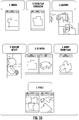
- the measuring principle is based on a signal that is emitted from the devices, redirected at the surface around the target point, and received by the device again (see FIG. 1 ).
- the user places the device parallel to the wall and uses a neighboring wall as target.
- FIGS. 2 and 3 display two options using different reference points for measuring.
- FIG. 4 displays the working principle of a laser scanner.
- Most laser scanners use moveable mirrors to steer the laser beam. A precise steering of laser beams enables distance measurements at every pointing direction.
- This method often called 3D object scanning or 3D laser scanning, is used to rapidly capture shapes of objects, buildings and landscapes. How fast scans can be developed is affected by the speed at which the mirror can be adjusted.
- EP 1 669 776 A1 relates to a handheld measurement appliance having at least one distance/spacing meter, preferably a laser distance meter with a directional emission and an evaluating unit/component for deriving and preparing the measured spacing and distances.
- a position detection unit/component is used with common storage especially with linked assessment for each spacing/distance measurement.
- By moving the appliance within a measurement space different distances are measured, which are combined with each other in order to determine the dimensions of objects.
- edges of an object such as a table can be determined, which allows determining the distance between the edges of the table. It is also possible to determine the angle between walls of the room.
- a handheld sensing device comprising a portable housing defining a measurement direction.
- a distance measurement unit is supported by the housing and configured to measure a distance to a remote point in the measurement direction.
- An inertial measurement unit is also supported by the housing and configured to perform an inertial measurement in association with each distance measurement.
- the device also includes a processor configured to process the distance measurements with reference to the associated inertial measurements to determine a geometric characteristic of a measurement object.
- a method of using the handheld sensing device comprises performing a laser sweep of a measurement object with the handheld sensing device.
- the method includes activating the distance measurement unit is to perform a plurality of distance measurements during the laser sweep and activating the inertial measurement unit to perform an inertial measurement in association with each of the distance measurements.
- a processor is used to process the distance measurements with reference to the associated inertial measurements to determine a geometric characteristic of the measurement object.
- the distance measurement unit may comprise an optical sensing device, such as a laser range finder.
- the inertial measurement unit comprises inertial sensing devices, such as one or more accelerometers, gyroscopes, and/or compasses, that are configured to detect a position and orientation of the handheld measuring device.
- the distance measurement unit and the inertial measurement unit may be activated at high frequencies to take measurements, e.g., at least 30Hz.
- the processor may be configured to use prior knowledge to enhance the accuracy of measurements. Prior knowledge may include user characteristics, such as forearm length and wrist to sensor distances, and may also include certain assumptions, such as the measurement points being located in plane (which is typically the case when measuring a wall).
- the processor may be configured to perform various functions using the measured data from the distance measurement unit and the inertial measurement unit.
- the functions may be defined by programmed instructions stored in an electronic memory.
- the programmed instructions may include instructions for causing the processor to generate a 3D point collection for the measurement object from the distance measurements and the associated inertial measurements and to store the 3D point collection in the memory, to process the distance measurements with reference to the associated inertial measurements to determine a dimension of a surface of the measurement object, and/or to process the distance measurements with reference to the associated inertial measurements to indirectly determine an angle between two surfaces of the measurement object.
- the handheld sensor device may be operated via a user interface which may be incorporated into the housing of the device.
- the user interface may comprise any suitable type of device capable of inputting commands and data to the processor.
- the user interface may include a touch screen display that enables a visualization of the data measurements and processed data.
- the processor is configured to process the distance measurements and inertial measurements to generate images or graphics which depict the data in a user friendly manner.
- the handheld measuring device includes a communication system which enables data to be wirelessly transmitted and received to and from a remote device, such as a smart device, smart phone, tablet, or computer.
- a remote device such as a smart device, smart phone, tablet, or computer.
- the remote device may be configured to provide further processing and visualization capabilities for the measured data.
- the handheld sensing device may further comprise an image capturing device, such as a camera, for capturing images of the measurement object.
- the processor may be configured to process the captured images to form a panoramic image of the measurement object.
- the processor may also be configured to associate measured points to the corresponding points in the panoramic image.
- the disclosure proposes systems and methods for combining a fast measuring Laser Range Finder (LRF) with an Inertial Measurement Unit (IMU) into a single unit ( FIG. 6 ) to enable laser scanning using hand gestures.
- LRF Laser Range Finder
- IMU Inertial Measurement Unit
- the systems and methods of combining the precise distance measures of an LRF with inertial measurements from an IMU accelerometer, gyroscope, and compass indirect measurements of distances and angles produced by the LRF and IMU enables a user of such a hand-held device to create three dimensional laser scans.
- the IMU is rigidly attached to the LRF and continuously measures its velocity, orientation, and the gravitational force as the device is moved by an operator. With well known techniques, those measurements can be combined to track the 3D position and 3D orientation (6 Degree-of-Freedom (6DoF) pose) of the laser range finder.
- 6DoF Degree-of-Freedom
- Combining the 3D motion tracking and a fast measuring laser range finder allows the collection of distance measurements to be synchronized with 6DoF pose measurements at a high frequency (e.g. 30 Hz). Applying the 6DoF poses to the corresponding distance measures yields to a collection of 3D point positions. In case the user does a sweep-like hand gesture the resulting 3D point collection looks approximately like a single 2D scan line gathered from a 2D laser scanner ( FIG. 7 ).
- a sweep-like hand gesture combined with the underlying data processing of motion tracking and fast scanning is referred to herein a "laser sweep”.
- the sweep gesture itself does not require a larger translational motion and is itself rather fast ( ⁇ 1 sec).
- Using advanced filter methods in combination with rather short and mainly rotational motions lead to accurate and stable 6DoF pose estimations ( FIG. 8 ).
- the velocity of the hand motion is zero whenever the user switches the direction of rotation; the length of the forearm can be determined and used in cases of sweep gestures which rotate around the elbow; the distance between wrist and laser range finder can be determined and used in case of a wrist-based sweep gesture; and 3D points can be assumed to form clusters on planes (walls) in indoor environments. Fusing such prior knowledge in a sophisticated motion estimation framework leads to a stable pose estimation of the laser range finder while performing a laser sweep.
- the integration of further knowledge is optional and not required to perform single distance, angle, and area measurements or generated 2D floor plans and 3D room reconstructions.
- the hardware setup for a laser sweep system comprises an advanced laser range finder with an additional inertial measurement unit to track the motion of the laser device and a fast scanning mode to measure distances with a high frequency.
- these devices can be combined into the same housing to form a single hand-held unit.
- the LRF and IMU functionality may be provided in separate devices that are connected together.
- the LRF may be provided in one device and the IMU may be implemented in a separate device, such as smart phone.
- a smart phone accessory may be configured to physically connect the smart phone and LRF (See, e.g., FIG. 27 ).
- separate devices may be connected via a suitably fast connection which can be wireless, e.g., Bluetooth, or wired, e.g., serial cable.
- a laser sweep system such as described above, enables indirect single distance measurements using laser sweep technology.
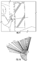
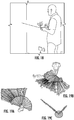
- An example of an indirect distance measurement is the measurement of single wall dimensions. The user needs to sweep the laser over the wall ( FIG. 9 ) to collect a set of 3D points lying on the wall ( FIG. 10 ).
- the next step is to reduce the collection of 3D points to a collection of 2D points. This can be done by projecting all points onto a plane using an orthogonal projection. Based on accelerometer measurements (gravity) and the assumption that the user is attempting to measure a horizontal distance (wall width) the best plane for projection is the plane described by the floor. This projection leads to a birds-eye view of the generated data ( FIG. 11 ).
- the next step towards getting the dimensions of the measured wall is a detection and segmentation of lines in the 2D point set. Using robust line detection algorithms like RANSAC or Hough transform, the number of 2D point clusters containing 2D points which all correspond to the same 2D line can be estimated ( FIG. 12 ).
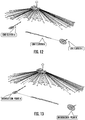
- a laser sweep with the device enables an indirect measurement of angles, e.g. the angle between two adjacent walls ( FIG. 18 ).
- the user just needs to sweep the laser over the two adjacent walls.
- an estimate for two accurate 2D lines for the two involved walls can be determined ( FIG. 19c ).
- FIGS. 20 and 21 show an example of the data points and line estimates attained for a 140 degree angle between two walls which could not be obtained using the current state-of-the-art laser range finders.
- a laser sweep system can be operated via simple user interface on a display of the device itself.
- the device may be configured to be connected with other devices, such as smart phones, tablets, and computers, to enable advanced user interfaces.
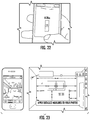
- the laser sweep device may be connected wirelessly to a smart device, such as a phone or tablet (e.g., via Bluetooth), and operated through an advanced user interface implemented by an application, or app, on the smart device ( FIG. 22 ).
- a smart device such as a phone or tablet (e.g., via Bluetooth)
- an application, or app on the smart device ( FIG. 22 ).
- These user interfaces can be used for various purposes, such as visualization of the estimated data only, to give online feedback to the user while sweeping, or to actively interact with the user and leverage from user input.
- the laser sweep system may include an image capturing device, such as a camera ( FIG. 23 ), to enable further types of measurements and data gathering to be performed.
- Image based measurements such as depicted in FIG. 23 , are known.
- This disclosure proposes that the laser sweep measurements be used in conjunction with panoramic image processing to generate a corresponding panorama image while sweeping the laser over e.g. a wall ( FIG. 24 ).
- This panorama generation can be done using a smart phone camera or an integrated camera in the device.
- the calibration between camera and laser range finder can be provided after manufacturing.
- a manual calibration process can be performed, e.g., by panning/scaling/rotating the scan line to the right image position ( FIGS. 25a and 25b ).
- the manual calibration can be done intuitively using finger gestures on the smart phone. Once the calibration between panorama and sweep line is known (either through automatic or manual calibration), arbitrary additional metric measures on the same wall can be taken ( FIG. 26 ). This functionality allows for a rapid documentation of measured distances and in addition to that it can be used to measure additional distances on the same wall later on.
- the image data can support fitting lines and intersection points in the generated 3D point collection. Using image data to guide the search for lines in the 3D point cloud can lead to a more robust and accurate estimate of room primitives.
- the 3D point cloud can also be used to guide and support the segmentation of the image data onto floors, walls, and other areas.
- the image data can be used for automatic feature detection.
- Features such as doors, windows, power outlets, light switches and other switches, ceiling lights, HVAC ducts, heating radiators, sprinklers, and the like, can be detected automatically using state of the art image feature recognition and placed automatically in the image and the generated 3D model. If the user would like to have a highly accurate measure of the position of these features, the user can be asked to measure these features again using the laser measurement device.
- image data In addition to use the image data just for visualization and for detecting room features like doors and windows it can be used to stabilize the motion tracking of the laser sweep device.
- Detecting and tracking of image features enable a vision / photogrammetry based motion tracking using established techniques called visual odometry, structure-from-motion or visual simultaneous localization and mapping.
- a vision based motion tracking allows larger translational motions during the sweep gesture and it prevents a tracking drift over time, which occurs in case only inertial measurements are being used.
- the IMU can be used to stabilize the vision based tracking system in environments with scarce visual texture.
- Image analysis techniques such as mentioned above and others, may be built into the system to enable calibration of the device as well as to implement other features. These techniques can be executed by a processor incorporated into the device.
- Programmed instructions with algorithms for implementing various image analysis techniques such as 2D and 3D object recognition, image segmentation, motion detection, optical flow, pose estimation, and the like, can be incorporated into the device for execution by the processor in conjunction with the laser sweep measurements discussed above.
- the processor of the device may be configured to perform any type of analysis on the sensor and image data to enhance or add to the functionality of the device. For example, the photogrammetric analysis of images and/or e.g. edge-detection to support interpretation of laser sweep data or vice versa, may be incorporated into the system.
- the laser sweep enables a simple indirect area measurement by combining one horizontal and one vertical sweep on the same wall ( FIGS. 29 and 30 ).
- the "negative response" from a laser sweep e.g. while sweeping over a window area
- This negative response information can also be used as prior knowledge for an image based refined window detection.
- advanced computer vision techniques for classification and object recognition the automatic detection of doors, windows, power outlets, etc. would enable an automatic measuring of all those dimensions ( FIG. 32 ).
- 2D floor plans and 3D models can also be generated from the data collected using the laser sweep system.
- An example of a process for generating 2D floor plans and 3D models is depicted in FIG. 33 .
- the process begins by sketching the area to that is to be measured (block 1). This can be performed via the user interface of the device itself and saved in the device's memory (block 2). Horizontal distance measurements are performed to determine the lengths of the walls (block 3). These measurements are stored in association with the corresponding walls.
- a 3D model may then be generated from the measurements (block 5).
- the 2D floor plans and 3D models for multiple connected rooms and spaces of a building, for example, can be then be merged (block 6) to produce a combined floor plan and model for the building (block 7).
Claims (13)
- Verfahren zum Durchführen geometrischer Messungen ferner Objekte, wobei das Verfahren Folgendes umfasst:Durchführen eines Laserschwenks über ein Messobjekt mit einer handgeführten Sensorvorrichtung, wobei die handgeführte Sensorvorrichtung eine Abstandsmesseinheit und eine Trägheitsmesseinheit beinhaltet, wobei die Abstandsmesseinheit dazu gestaltet ist, einen Abstand zu einem Punkt auf dem Objekt in einer Messrichtung zu messen, wobei die Messrichtung durch eine Ausrichtung der handgeführten Sensorvorrichtung definiert wird;Aktivieren der Abstandsmesseinheit, um mehrere Abstandsmessungen während des Laserschwenks durchzuführen;Aktivieren der Trägheitsmesseinheit, um eine Trägheitsmessung in Verbindung mit jeder der Abstandsmessungen durchzuführen, wobei die Trägheitsmessungen Positions- und Ausrichtungsdaten bezüglich der handgeführten Messvorrichtung beinhalten;Verwenden eines Prozessors, um die Abstandsmessungen in Bezug auf die mit ihnen verbundenen Trägheitsmessungen zu verarbeiten, um ein geometrisches Charakteristikum des Messobjekts zu bestimmen, wobei die Trägheitsmessungen Positions- und Ausrichtungsdaten bezüglich der handgeführten Messvorrichtung beinhalten;Verwenden des Prozessors, um eine 3D-Punktsammlung für das Messobjekt aus den Abstandsmessungen und den mit ihnen verbundenen Trägheitsmessungen zu erzeugen,gekennzeichnet durchVerwenden des Prozessors, um die 3D-Punktsammlung auf eine Sammlung von 2D-Punkten zu reduzieren;Verwenden des Prozessors zur Erkennung und Segmentierung von Linien in der 2D-Punktsammlung;Verwenden des Prozessors, um Schnittpunkte zwischen 2D-Linien zu berechnen; undVerwenden des Prozessors, um basierend auf dem euklidischen Abstand zwischen den Schnittpunkten die Abmessung einer Wand zu schätzen oder basierend auf dem Winkel zwischen zwei sich schneidenden 2D-Linien einen Winkel zwischen zwei Wänden zu schätzen.
- Verfahren nach Anspruch 1, wobei die Abstandsmesseinheit einen Laserentfernungsmesser umfasst.
- Verfahren nach Anspruch 1, wobei die Abstandsmesseinheit und die Trägheitsmesseinheit bei einer Frequenz von mindestens 30 Hz aktiviert werden.
- Verfahren nach Anspruch 1, wobei der Prozessor dazu gestaltet ist, bei der Bestimmung des geometrischen Charakteristikums des Messobjekts Nutzercharakteristika zu berücksichtigen, wobei die Nutzercharakteristika mindestens eines von einer Unterarmlänge und einem Abstand zwischen einem Handgelenk des Nutzers und dem Laserentfernungsmesser beinhalten.
- Verfahren nach Anspruch 1, wobei das Aktivieren der Abstandsmesseinheit ferner Folgendes umfasst:
Aktivieren der Abstandsmesseinheit über eine Nutzerschnittstelle der handgeführten Messvorrichtüng. - Verfahren nach Anspruch 5, wobei die Nutzerschnittstelle eine Berührungsbildschirm-Schnittstelle umfasst.
- Verfahren nach Anspruch 5, ferner umfassend:
drahtloses Übertragen mindestens einer der Abstandsmessungen, der Trägheitsmessungen und des geometrischen Charakteristikums zu einer fernen Vorrichtung. - Verfahren nach Anspruch 7, wobei die ferne Vorrichtung eine intelligente Vorrichtung ist.
- Verfahren nach Anspruch 1, wobei die handgeführte Abtastvorrichtung ferner eine Bildaufnahmevorrichtung umfasst und das Verfahren ferner Folgendes umfasst:Aktivieren der Bildaufnahmevorrichtung, um während des Laserschwenks ein Panoramabild aufzunehmen; undVerwenden des Prozessors, um Abstandsmessungen mit Punkten in dem Panoramabild zu verbinden.
- Handgeführte Abtastvorrichtung, umfassend:ein tragbares Gehäuse, das eine Messrichtung definiert;eine Abstandsmesseinheit, die von dem Gehäuse getragen wird und dazu gestaltet ist, einen Abstand zu einem fernen Punkt in der Messrichtung zu messen;eine Trägheitsmesseinheit, die von dem Gehäuse getragen wird und dazu gestaltet ist, eine Trägheitsmessung in Verbindung mit jeder Abstandsmessung durchzuführen, und die mindestens eines von einem Beschleunigungsmesser, einem Gyroskop und einem Kompass umfasst; undeinen Prozessor, der dazu gestaltet ist, die Abstandsmessungen in Bezug auf die mit ihnen verbundenen Trägheitsmessungen zu verarbeiten, um ein geometrisches Charakteristikum eines Messobjekts zu bestimmen,eine 3D-Punktsammlung für das Messobjekt aus den Abstandsmessungen und den mit ihnen verbundenen Trägheitsmessungen zu erzeugen,dadurch gekennzeichnet, dass der Prozessor ferner dazu gestaltet ist,die 3D-Punktsammlung auf eine Sammlung von 2D-Punkten zu reduzieren,eine Erkennung und Segmentierung von Linien in der 2D-Punktsammlung durchzuführen,Schnittpunkte zwischen 2D-Linien zu berechnen undbasierend auf dem euklidischen Abstand zwischen den Schnittpunkten die Abmessung einer Wand zu schätzen oder basierend auf dem Winkel zwischen zwei sich schneidenden 2D-Linien einen Winkel zwischen zwei Wänden zu schätzen.
- Handgeführte Abtastvorrichtung nach Anspruch 10, wobei die Abstandsmesseinheit einen Laserentfernungsmesser umfasst.
- Handgeführte Abtastvorrichtung nach Anspruch 10, wobei der Prozessor dazu gestaltet ist, eine 3D-Punktsammlung für das Messobjekt aus den Abstandsmessungen und den mit ihnen verbundenen Trägheitsmessungen zu erzeugen.
- Handgeführte Abtastvorrichtung nach Anspruch 10, ferner eine Bildaufnahmevorrichtung umfassend, die dazu gestaltet ist, ein Panoramabild des Messobjekts aufzunehmen, und
wobei der Prozessor dazu gestaltet ist, Abstandsmessungen mit Punkten in dem Panoramabild zu verbinden.
Applications Claiming Priority (3)
| Application Number | Priority Date | Filing Date | Title |
|---|---|---|---|
| US201361898696P | 2013-11-01 | 2013-11-01 | |
| US201361910348P | 2013-11-30 | 2013-11-30 | |
| PCT/US2014/063144 WO2015066319A1 (en) | 2013-11-01 | 2014-10-30 | System and method for measuring by laser sweeps |
Publications (3)
| Publication Number | Publication Date |
|---|---|
| EP3063553A1 EP3063553A1 (de) | 2016-09-07 |
| EP3063553A4 EP3063553A4 (de) | 2017-06-21 |
| EP3063553B1 true EP3063553B1 (de) | 2019-12-11 |
Family
ID=53005114
Family Applications (1)
| Application Number | Title | Priority Date | Filing Date |
|---|---|---|---|
| EP14857984.0A Active EP3063553B1 (de) | 2013-11-01 | 2014-10-30 | System und verfahren zur messung mittels lasersweeps |
Country Status (3)
| Country | Link |
|---|---|
| US (1) | US10060730B2 (de) |
| EP (1) | EP3063553B1 (de) |
| WO (1) | WO2015066319A1 (de) |
Families Citing this family (26)
| Publication number | Priority date | Publication date | Assignee | Title |
|---|---|---|---|---|
| WO2015123348A1 (en) * | 2014-02-11 | 2015-08-20 | Xactware Solutions, Inc. | System and method for generating computerized floor plans |
| CN107667366B (zh) * | 2015-03-24 | 2021-12-28 | 开利公司 | 用于捕获和分析多维建筑物信息的系统和方法 |
| CA3007968A1 (en) | 2015-12-09 | 2017-06-15 | Geomni, Inc. | System and method for generating computerized models of structures using geometry extraction and reconstruction techniques |
| EP3182157B1 (de) * | 2015-12-14 | 2020-04-15 | Leica Geosystems AG | Verfahren zur erzeugung eines räumlichen modells mit einer tragbaren distanzmessungsvorrichtung |
| DE102016007219B9 (de) * | 2016-06-14 | 2017-11-30 | Kaleas GmbH & Co. KG | Verfahren und Messvorrichtung zur Bestimmung eines Winkels |
| WO2017222558A1 (en) * | 2016-06-24 | 2017-12-28 | Isee, Inc. | Laser-enhanced visual simultaneous localization and mapping (slam) for mobile devices |
| AU2017294796B2 (en) | 2016-07-15 | 2019-05-30 | Fastbrick Ip Pty Ltd | Brick/block laying machine incorporated in a vehicle |
| AU2017294795B2 (en) | 2016-07-15 | 2019-06-13 | Fastbrick Ip Pty Ltd | Boom for material transport |
| WO2018105117A1 (ja) * | 2016-12-09 | 2018-06-14 | 三菱電機ビルテクノサービス株式会社 | 工事写真管理システム |
| US10824773B2 (en) * | 2017-03-28 | 2020-11-03 | Faro Technologies, Inc. | System and method of scanning an environment and generating two dimensional images of the environment |
| DE102017107341B4 (de) * | 2017-04-05 | 2018-10-31 | Testo SE & Co. KGaA | Verfahren und Vorrichtung zur Bestimmung einer geometrischen Messgröße eines Objektes |
| EP3649616A4 (de) | 2017-07-05 | 2021-04-07 | Fastbrick IP Pty Ltd | Positions- und orientierungsverfolger in echtzeit |
| CN111226090B (zh) | 2017-08-17 | 2023-05-23 | 快砖知识产权私人有限公司 | 具有改进的横滚角测量的激光跟踪器 |
| CN111246976B (zh) | 2017-08-17 | 2024-03-15 | 快砖知识产权私人有限公司 | 交互系统配置 |
| WO2019071313A1 (en) | 2017-10-11 | 2019-04-18 | Fastbrick Ip Pty Ltd | MACHINE FOR CARRYING OBJECTS AND CARROUSEL WITH SEVERAL COMPARTMENTS FOR USE WITH THE SAME |
| CA3082516A1 (en) | 2017-11-13 | 2019-05-16 | Geomni, Inc. | Systems and methods for rapidly developing annotated computer models of structures |
| CN108286951B (zh) * | 2018-01-16 | 2021-05-04 | 常景测量科技(武汉)有限公司 | 用于室内门窗测量的手持式激光扫描仪 |
| US10546419B2 (en) * | 2018-02-14 | 2020-01-28 | Faro Technologies, Inc. | System and method of on-site documentation enhancement through augmented reality |
| US11055532B2 (en) | 2018-05-02 | 2021-07-06 | Faro Technologies, Inc. | System and method of representing and tracking time-based information in two-dimensional building documentation |
| US10830473B2 (en) | 2018-05-14 | 2020-11-10 | Johnson Controls Technology Company | Systems and methods for zoning system setup |
| EP3857410A4 (de) * | 2018-09-24 | 2022-03-30 | Geomni, Inc. | System und verfahren zur erzeugung von bodenplänen mittels benutzergerätesensoren |
| US11024050B2 (en) | 2018-11-05 | 2021-06-01 | Faro Technologies, Inc. | System and method of scanning an environment |
| US11501478B2 (en) | 2020-08-17 | 2022-11-15 | Faro Technologies, Inc. | System and method of automatic room segmentation for two-dimensional laser floorplans |
| CN112902839B (zh) * | 2021-01-21 | 2022-05-20 | 华中科技大学 | 一种基于点激光位移传感器的加工余量测量方法和系统 |
| WO2022204559A1 (en) | 2021-03-25 | 2022-09-29 | Insurance Services Office, Inc. | Computer vision systems and methods for generating building models using three-dimensional sensing and augmented reality techniques |
| EP4141384A1 (de) | 2021-08-31 | 2023-03-01 | Safran Vectronix AG | Handgehaltene beobachtungsvorrichtung und verfahren zur erzeugung einer 3d-punktwolke |
Family Cites Families (10)
| Publication number | Priority date | Publication date | Assignee | Title |
|---|---|---|---|---|
| US6895356B2 (en) | 2003-08-14 | 2005-05-17 | Rubicon Digital Mapping Associates | Integrated laser mapping tablet and method of use |
| EP1669776A1 (de) * | 2004-12-11 | 2006-06-14 | Leica Geosystems AG | Handhaltbares Vermessungsgerät und Vermessungsverfahren für ein solches Vermessungsgerät |
| US7755360B1 (en) * | 2005-10-24 | 2010-07-13 | Seektech, Inc. | Portable locator system with jamming reduction |
| JP5097480B2 (ja) | 2007-08-29 | 2012-12-12 | 株式会社トプコン | 画像測定装置 |
| DE102008054453A1 (de) | 2008-12-10 | 2010-06-17 | Robert Bosch Gmbh | Messsystem zur Vermessung von Räumen und/oder von Objekten |
| US8615376B2 (en) | 2010-05-21 | 2013-12-24 | Sure-Shot Medical Device Inc. | Method and apparatus for dimensional measurement |
| US9599715B2 (en) * | 2010-08-03 | 2017-03-21 | Faro Technologies, Inc. | Scanner display |
| US9349195B2 (en) | 2012-03-19 | 2016-05-24 | Google Inc. | Apparatus and method for spatially referencing images |
| JP2014021703A (ja) * | 2012-07-18 | 2014-02-03 | Sony Corp | ポインティングデバイス及び撮像装置 |
| US9131335B2 (en) * | 2013-08-22 | 2015-09-08 | Nokia Technologies Oy | Method, apparatus, and computer program product for management of connected devices, such as in a wireless docking environment |
-
2014
- 2014-10-30 EP EP14857984.0A patent/EP3063553B1/de active Active
- 2014-10-30 WO PCT/US2014/063144 patent/WO2015066319A1/en active Application Filing
- 2014-10-30 US US15/033,011 patent/US10060730B2/en active Active
Non-Patent Citations (1)
| Title |
|---|
| None * |
Also Published As
| Publication number | Publication date |
|---|---|
| EP3063553A1 (de) | 2016-09-07 |
| EP3063553A4 (de) | 2017-06-21 |
| WO2015066319A1 (en) | 2015-05-07 |
| US10060730B2 (en) | 2018-08-28 |
| US20160282107A1 (en) | 2016-09-29 |
Similar Documents
| Publication | Publication Date | Title |
|---|---|---|
| EP3063553B1 (de) | System und verfahren zur messung mittels lasersweeps | |
| EP2973414B1 (de) | Vorrichtung zur erzeugung eines raummodells | |
| US8699005B2 (en) | Indoor surveying apparatus | |
| US10481265B2 (en) | Apparatus, systems and methods for point cloud generation and constantly tracking position | |
| US9888215B2 (en) | Indoor scene capture system | |
| CN110801180B (zh) | 清洁机器人的运行方法及装置 | |
| EP3639218A1 (de) | Verfahren und system zur erzeugung einer adaptiven projizierten realität auf baustellen | |
| RU2572637C2 (ru) | Параллельное или выполняемое последовательно в онлайн- и оффлайн- режимах формирование реконструкций для трехмерного обмера помещения | |
| JP6636042B2 (ja) | 床の処理方法 | |
| TW201337306A (zh) | 用於建築工地之資訊擷取 | |
| Ye et al. | 6-DOF pose estimation of a robotic navigation aid by tracking visual and geometric features | |
| US11015930B2 (en) | Method for 2D picture based conglomeration in 3D surveying | |
| WO2019001237A1 (zh) | 一种移动电子设备以及该移动电子设备中的方法 | |
| US20150317070A1 (en) | Mobile handheld instruments and methods | |
| US20230154027A1 (en) | Spatial construction using guided surface detection | |
| US10447991B1 (en) | System and method of mapping elements inside walls | |
| Senthilvel et al. | Comparison of handheld devices for 3D reconstruction in construction | |
| US20220130064A1 (en) | Feature Determination, Measurement, and Virtualization From 2-D Image Capture | |
| US11936843B2 (en) | Generating textured three-dimensional meshes using two-dimensional scanner and panoramic camera | |
| CN219301516U (zh) | 一种测量系统 | |
| WO2019037517A1 (zh) | 一种用于处理任务区域的任务的移动电子设备以及方法 | |
| US20230326098A1 (en) | Generating a digital twin representation of an environment or object | |
| EP4332631A1 (de) | Globale optimierungsverfahren für mobile koordinatenscanner | |
| KR102193976B1 (ko) | 실내공간 내 사물의 정보 확인이 가능한 클라우드 이용 3d 실내공간 서비스 방법 및 시스템 |
Legal Events
| Date | Code | Title | Description |
|---|---|---|---|
| PUAI | Public reference made under article 153(3) epc to a published international application that has entered the european phase |
Free format text: ORIGINAL CODE: 0009012 |
|
| 17P | Request for examination filed |
Effective date: 20160601 |
|
| AK | Designated contracting states |
Kind code of ref document: A1 Designated state(s): AL AT BE BG CH CY CZ DE DK EE ES FI FR GB GR HR HU IE IS IT LI LT LU LV MC MK MT NL NO PL PT RO RS SE SI SK SM TR |
|
| AX | Request for extension of the european patent |
Extension state: BA ME |
|
| DAX | Request for extension of the european patent (deleted) | ||
| REG | Reference to a national code |
Ref country code: DE Ref legal event code: R079 Ref document number: 602014058396 Country of ref document: DE Free format text: PREVIOUS MAIN CLASS: G01S0017890000 Ipc: G01S0017420000 |
|
| A4 | Supplementary search report drawn up and despatched |
Effective date: 20170518 |
|
| RIC1 | Information provided on ipc code assigned before grant |
Ipc: G01S 7/48 20060101ALI20170512BHEP Ipc: G01S 17/42 20060101AFI20170512BHEP Ipc: G01S 17/89 20060101ALI20170512BHEP Ipc: G01S 17/02 20060101ALI20170512BHEP |
|
| GRAP | Despatch of communication of intention to grant a patent |
Free format text: ORIGINAL CODE: EPIDOSNIGR1 |
|
| STAA | Information on the status of an ep patent application or granted ep patent |
Free format text: STATUS: GRANT OF PATENT IS INTENDED |
|
| INTG | Intention to grant announced |
Effective date: 20190919 |
|
| GRAS | Grant fee paid |
Free format text: ORIGINAL CODE: EPIDOSNIGR3 |
|
| GRAA | (expected) grant |
Free format text: ORIGINAL CODE: 0009210 |
|
| STAA | Information on the status of an ep patent application or granted ep patent |
Free format text: STATUS: THE PATENT HAS BEEN GRANTED |
|
| AK | Designated contracting states |
Kind code of ref document: B1 Designated state(s): AL AT BE BG CH CY CZ DE DK EE ES FI FR GB GR HR HU IE IS IT LI LT LU LV MC MK MT NL NO PL PT RO RS SE SI SK SM TR |
|
| REG | Reference to a national code |
Ref country code: GB Ref legal event code: FG4D |
|
| REG | Reference to a national code |
Ref country code: CH Ref legal event code: EP |
|
| REG | Reference to a national code |
Ref country code: AT Ref legal event code: REF Ref document number: 1212753 Country of ref document: AT Kind code of ref document: T Effective date: 20191215 |
|
| REG | Reference to a national code |
Ref country code: DE Ref legal event code: R096 Ref document number: 602014058396 Country of ref document: DE |
|
| REG | Reference to a national code |
Ref country code: IE Ref legal event code: FG4D |
|
| REG | Reference to a national code |
Ref country code: NL Ref legal event code: MP Effective date: 20191211 |
|
| REG | Reference to a national code |
Ref country code: LT Ref legal event code: MG4D |
|
| RAP2 | Party data changed (patent owner data changed or rights of a patent transferred) |
Owner name: ROBERT BOSCH GMBH |
|
| PG25 | Lapsed in a contracting state [announced via postgrant information from national office to epo] |
Ref country code: BG Free format text: LAPSE BECAUSE OF FAILURE TO SUBMIT A TRANSLATION OF THE DESCRIPTION OR TO PAY THE FEE WITHIN THE PRESCRIBED TIME-LIMIT Effective date: 20200311 Ref country code: FI Free format text: LAPSE BECAUSE OF FAILURE TO SUBMIT A TRANSLATION OF THE DESCRIPTION OR TO PAY THE FEE WITHIN THE PRESCRIBED TIME-LIMIT Effective date: 20191211 Ref country code: SE Free format text: LAPSE BECAUSE OF FAILURE TO SUBMIT A TRANSLATION OF THE DESCRIPTION OR TO PAY THE FEE WITHIN THE PRESCRIBED TIME-LIMIT Effective date: 20191211 Ref country code: LV Free format text: LAPSE BECAUSE OF FAILURE TO SUBMIT A TRANSLATION OF THE DESCRIPTION OR TO PAY THE FEE WITHIN THE PRESCRIBED TIME-LIMIT Effective date: 20191211 Ref country code: NO Free format text: LAPSE BECAUSE OF FAILURE TO SUBMIT A TRANSLATION OF THE DESCRIPTION OR TO PAY THE FEE WITHIN THE PRESCRIBED TIME-LIMIT Effective date: 20200311 Ref country code: GR Free format text: LAPSE BECAUSE OF FAILURE TO SUBMIT A TRANSLATION OF THE DESCRIPTION OR TO PAY THE FEE WITHIN THE PRESCRIBED TIME-LIMIT Effective date: 20200312 Ref country code: LT Free format text: LAPSE BECAUSE OF FAILURE TO SUBMIT A TRANSLATION OF THE DESCRIPTION OR TO PAY THE FEE WITHIN THE PRESCRIBED TIME-LIMIT Effective date: 20191211 |
|
| PG25 | Lapsed in a contracting state [announced via postgrant information from national office to epo] |
Ref country code: HR Free format text: LAPSE BECAUSE OF FAILURE TO SUBMIT A TRANSLATION OF THE DESCRIPTION OR TO PAY THE FEE WITHIN THE PRESCRIBED TIME-LIMIT Effective date: 20191211 Ref country code: RS Free format text: LAPSE BECAUSE OF FAILURE TO SUBMIT A TRANSLATION OF THE DESCRIPTION OR TO PAY THE FEE WITHIN THE PRESCRIBED TIME-LIMIT Effective date: 20191211 |
|
| PG25 | Lapsed in a contracting state [announced via postgrant information from national office to epo] |
Ref country code: AL Free format text: LAPSE BECAUSE OF FAILURE TO SUBMIT A TRANSLATION OF THE DESCRIPTION OR TO PAY THE FEE WITHIN THE PRESCRIBED TIME-LIMIT Effective date: 20191211 |
|
| PG25 | Lapsed in a contracting state [announced via postgrant information from national office to epo] |
Ref country code: EE Free format text: LAPSE BECAUSE OF FAILURE TO SUBMIT A TRANSLATION OF THE DESCRIPTION OR TO PAY THE FEE WITHIN THE PRESCRIBED TIME-LIMIT Effective date: 20191211 Ref country code: ES Free format text: LAPSE BECAUSE OF FAILURE TO SUBMIT A TRANSLATION OF THE DESCRIPTION OR TO PAY THE FEE WITHIN THE PRESCRIBED TIME-LIMIT Effective date: 20191211 Ref country code: RO Free format text: LAPSE BECAUSE OF FAILURE TO SUBMIT A TRANSLATION OF THE DESCRIPTION OR TO PAY THE FEE WITHIN THE PRESCRIBED TIME-LIMIT Effective date: 20191211 Ref country code: NL Free format text: LAPSE BECAUSE OF FAILURE TO SUBMIT A TRANSLATION OF THE DESCRIPTION OR TO PAY THE FEE WITHIN THE PRESCRIBED TIME-LIMIT Effective date: 20191211 Ref country code: CZ Free format text: LAPSE BECAUSE OF FAILURE TO SUBMIT A TRANSLATION OF THE DESCRIPTION OR TO PAY THE FEE WITHIN THE PRESCRIBED TIME-LIMIT Effective date: 20191211 Ref country code: PT Free format text: LAPSE BECAUSE OF FAILURE TO SUBMIT A TRANSLATION OF THE DESCRIPTION OR TO PAY THE FEE WITHIN THE PRESCRIBED TIME-LIMIT Effective date: 20200506 |
|
| PG25 | Lapsed in a contracting state [announced via postgrant information from national office to epo] |
Ref country code: SM Free format text: LAPSE BECAUSE OF FAILURE TO SUBMIT A TRANSLATION OF THE DESCRIPTION OR TO PAY THE FEE WITHIN THE PRESCRIBED TIME-LIMIT Effective date: 20191211 Ref country code: IS Free format text: LAPSE BECAUSE OF FAILURE TO SUBMIT A TRANSLATION OF THE DESCRIPTION OR TO PAY THE FEE WITHIN THE PRESCRIBED TIME-LIMIT Effective date: 20200411 Ref country code: SK Free format text: LAPSE BECAUSE OF FAILURE TO SUBMIT A TRANSLATION OF THE DESCRIPTION OR TO PAY THE FEE WITHIN THE PRESCRIBED TIME-LIMIT Effective date: 20191211 |
|
| REG | Reference to a national code |
Ref country code: DE Ref legal event code: R097 Ref document number: 602014058396 Country of ref document: DE |
|
| REG | Reference to a national code |
Ref country code: AT Ref legal event code: MK05 Ref document number: 1212753 Country of ref document: AT Kind code of ref document: T Effective date: 20191211 |
|
| PLBE | No opposition filed within time limit |
Free format text: ORIGINAL CODE: 0009261 |
|
| STAA | Information on the status of an ep patent application or granted ep patent |
Free format text: STATUS: NO OPPOSITION FILED WITHIN TIME LIMIT |
|
| PG25 | Lapsed in a contracting state [announced via postgrant information from national office to epo] |
Ref country code: DK Free format text: LAPSE BECAUSE OF FAILURE TO SUBMIT A TRANSLATION OF THE DESCRIPTION OR TO PAY THE FEE WITHIN THE PRESCRIBED TIME-LIMIT Effective date: 20191211 |
|
| 26N | No opposition filed |
Effective date: 20200914 |
|
| PG25 | Lapsed in a contracting state [announced via postgrant information from national office to epo] |
Ref country code: AT Free format text: LAPSE BECAUSE OF FAILURE TO SUBMIT A TRANSLATION OF THE DESCRIPTION OR TO PAY THE FEE WITHIN THE PRESCRIBED TIME-LIMIT Effective date: 20191211 Ref country code: SI Free format text: LAPSE BECAUSE OF FAILURE TO SUBMIT A TRANSLATION OF THE DESCRIPTION OR TO PAY THE FEE WITHIN THE PRESCRIBED TIME-LIMIT Effective date: 20191211 |
|
| PG25 | Lapsed in a contracting state [announced via postgrant information from national office to epo] |
Ref country code: IT Free format text: LAPSE BECAUSE OF FAILURE TO SUBMIT A TRANSLATION OF THE DESCRIPTION OR TO PAY THE FEE WITHIN THE PRESCRIBED TIME-LIMIT Effective date: 20191211 |
|
| PG25 | Lapsed in a contracting state [announced via postgrant information from national office to epo] |
Ref country code: PL Free format text: LAPSE BECAUSE OF FAILURE TO SUBMIT A TRANSLATION OF THE DESCRIPTION OR TO PAY THE FEE WITHIN THE PRESCRIBED TIME-LIMIT Effective date: 20191211 |
|
| REG | Reference to a national code |
Ref country code: CH Ref legal event code: PL |
|
| GBPC | Gb: european patent ceased through non-payment of renewal fee |
Effective date: 20201030 |
|
| PG25 | Lapsed in a contracting state [announced via postgrant information from national office to epo] |
Ref country code: LU Free format text: LAPSE BECAUSE OF NON-PAYMENT OF DUE FEES Effective date: 20201030 Ref country code: MC Free format text: LAPSE BECAUSE OF FAILURE TO SUBMIT A TRANSLATION OF THE DESCRIPTION OR TO PAY THE FEE WITHIN THE PRESCRIBED TIME-LIMIT Effective date: 20191211 |
|
| REG | Reference to a national code |
Ref country code: BE Ref legal event code: MM Effective date: 20201031 |
|
| PG25 | Lapsed in a contracting state [announced via postgrant information from national office to epo] |
Ref country code: FR Free format text: LAPSE BECAUSE OF NON-PAYMENT OF DUE FEES Effective date: 20201031 |
|
| PG25 | Lapsed in a contracting state [announced via postgrant information from national office to epo] |
Ref country code: BE Free format text: LAPSE BECAUSE OF NON-PAYMENT OF DUE FEES Effective date: 20201031 Ref country code: CH Free format text: LAPSE BECAUSE OF NON-PAYMENT OF DUE FEES Effective date: 20201031 Ref country code: LI Free format text: LAPSE BECAUSE OF NON-PAYMENT OF DUE FEES Effective date: 20201031 Ref country code: GB Free format text: LAPSE BECAUSE OF NON-PAYMENT OF DUE FEES Effective date: 20201030 |
|
| PG25 | Lapsed in a contracting state [announced via postgrant information from national office to epo] |
Ref country code: IE Free format text: LAPSE BECAUSE OF NON-PAYMENT OF DUE FEES Effective date: 20201030 |
|
| PG25 | Lapsed in a contracting state [announced via postgrant information from national office to epo] |
Ref country code: TR Free format text: LAPSE BECAUSE OF FAILURE TO SUBMIT A TRANSLATION OF THE DESCRIPTION OR TO PAY THE FEE WITHIN THE PRESCRIBED TIME-LIMIT Effective date: 20191211 Ref country code: MT Free format text: LAPSE BECAUSE OF FAILURE TO SUBMIT A TRANSLATION OF THE DESCRIPTION OR TO PAY THE FEE WITHIN THE PRESCRIBED TIME-LIMIT Effective date: 20191211 Ref country code: CY Free format text: LAPSE BECAUSE OF FAILURE TO SUBMIT A TRANSLATION OF THE DESCRIPTION OR TO PAY THE FEE WITHIN THE PRESCRIBED TIME-LIMIT Effective date: 20191211 |
|
| PG25 | Lapsed in a contracting state [announced via postgrant information from national office to epo] |
Ref country code: MK Free format text: LAPSE BECAUSE OF FAILURE TO SUBMIT A TRANSLATION OF THE DESCRIPTION OR TO PAY THE FEE WITHIN THE PRESCRIBED TIME-LIMIT Effective date: 20191211 |
|
| REG | Reference to a national code |
Ref country code: DE Ref legal event code: R084 Ref document number: 602014058396 Country of ref document: DE |
|
| PGFP | Annual fee paid to national office [announced via postgrant information from national office to epo] |
Ref country code: DE Payment date: 20231218 Year of fee payment: 10 |