EP3063405B1 - Method of damping wind turbine tower oscillations - Google Patents
Method of damping wind turbine tower oscillations Download PDFInfo
- Publication number
- EP3063405B1 EP3063405B1 EP14789156.8A EP14789156A EP3063405B1 EP 3063405 B1 EP3063405 B1 EP 3063405B1 EP 14789156 A EP14789156 A EP 14789156A EP 3063405 B1 EP3063405 B1 EP 3063405B1
- Authority
- EP
- European Patent Office
- Prior art keywords
- tower
- bag
- wind turbine
- oscillations
- component
- Prior art date
- Legal status (The legal status is an assumption and is not a legal conclusion. Google has not performed a legal analysis and makes no representation as to the accuracy of the status listed.)
- Active
Links
- 238000013016 damping Methods 0.000 title claims description 48
- 230000010355 oscillation Effects 0.000 title claims description 47
- 238000000034 method Methods 0.000 title claims description 35
- 239000007788 liquid Substances 0.000 claims description 10
- 239000000463 material Substances 0.000 claims description 10
- 238000009434 installation Methods 0.000 claims description 6
- 238000003466 welding Methods 0.000 claims description 2
- 229910000831 Steel Inorganic materials 0.000 description 3
- 238000011900 installation process Methods 0.000 description 3
- 239000010959 steel Substances 0.000 description 3
- 238000005452 bending Methods 0.000 description 2
- 230000005540 biological transmission Effects 0.000 description 2
- 238000012986 modification Methods 0.000 description 2
- 230000004048 modification Effects 0.000 description 2
- 239000002131 composite material Substances 0.000 description 1
- 230000000694 effects Effects 0.000 description 1
- 230000005484 gravity Effects 0.000 description 1
- 230000000737 periodic effect Effects 0.000 description 1
- 239000004576 sand Substances 0.000 description 1
- 230000001131 transforming effect Effects 0.000 description 1
Images


Classifications
-
- F—MECHANICAL ENGINEERING; LIGHTING; HEATING; WEAPONS; BLASTING
- F03—MACHINES OR ENGINES FOR LIQUIDS; WIND, SPRING, OR WEIGHT MOTORS; PRODUCING MECHANICAL POWER OR A REACTIVE PROPULSIVE THRUST, NOT OTHERWISE PROVIDED FOR
- F03D—WIND MOTORS
- F03D80/00—Details, components or accessories not provided for in groups F03D1/00 - F03D17/00
- F03D80/80—Arrangement of components within nacelles or towers
- F03D80/88—Arrangement of components within nacelles or towers of mechanical components
-
- E—FIXED CONSTRUCTIONS
- E04—BUILDING
- E04H—BUILDINGS OR LIKE STRUCTURES FOR PARTICULAR PURPOSES; SWIMMING OR SPLASH BATHS OR POOLS; MASTS; FENCING; TENTS OR CANOPIES, IN GENERAL
- E04H9/00—Buildings, groups of buildings or shelters adapted to withstand or provide protection against abnormal external influences, e.g. war-like action, earthquake or extreme climate
- E04H9/02—Buildings, groups of buildings or shelters adapted to withstand or provide protection against abnormal external influences, e.g. war-like action, earthquake or extreme climate withstanding earthquake or sinking of ground
- E04H9/021—Bearing, supporting or connecting constructions specially adapted for such buildings
- E04H9/0215—Bearing, supporting or connecting constructions specially adapted for such buildings involving active or passive dynamic mass damping systems
-
- F—MECHANICAL ENGINEERING; LIGHTING; HEATING; WEAPONS; BLASTING
- F03—MACHINES OR ENGINES FOR LIQUIDS; WIND, SPRING, OR WEIGHT MOTORS; PRODUCING MECHANICAL POWER OR A REACTIVE PROPULSIVE THRUST, NOT OTHERWISE PROVIDED FOR
- F03D—WIND MOTORS
- F03D13/00—Assembly, mounting or commissioning of wind motors; Arrangements specially adapted for transporting wind motor components
- F03D13/10—Assembly of wind motors; Arrangements for erecting wind motors
-
- F—MECHANICAL ENGINEERING; LIGHTING; HEATING; WEAPONS; BLASTING
- F03—MACHINES OR ENGINES FOR LIQUIDS; WIND, SPRING, OR WEIGHT MOTORS; PRODUCING MECHANICAL POWER OR A REACTIVE PROPULSIVE THRUST, NOT OTHERWISE PROVIDED FOR
- F03D—WIND MOTORS
- F03D7/00—Controlling wind motors
- F03D7/02—Controlling wind motors the wind motors having rotation axis substantially parallel to the air flow entering the rotor
- F03D7/0296—Controlling wind motors the wind motors having rotation axis substantially parallel to the air flow entering the rotor to prevent, counteract or reduce noise emissions
-
- F—MECHANICAL ENGINEERING; LIGHTING; HEATING; WEAPONS; BLASTING
- F03—MACHINES OR ENGINES FOR LIQUIDS; WIND, SPRING, OR WEIGHT MOTORS; PRODUCING MECHANICAL POWER OR A REACTIVE PROPULSIVE THRUST, NOT OTHERWISE PROVIDED FOR
- F03D—WIND MOTORS
- F03D80/00—Details, components or accessories not provided for in groups F03D1/00 - F03D17/00
-
- F—MECHANICAL ENGINEERING; LIGHTING; HEATING; WEAPONS; BLASTING
- F16—ENGINEERING ELEMENTS AND UNITS; GENERAL MEASURES FOR PRODUCING AND MAINTAINING EFFECTIVE FUNCTIONING OF MACHINES OR INSTALLATIONS; THERMAL INSULATION IN GENERAL
- F16F—SPRINGS; SHOCK-ABSORBERS; MEANS FOR DAMPING VIBRATION
- F16F7/00—Vibration-dampers; Shock-absorbers
- F16F7/10—Vibration-dampers; Shock-absorbers using inertia effect
-
- F—MECHANICAL ENGINEERING; LIGHTING; HEATING; WEAPONS; BLASTING
- F05—INDEXING SCHEMES RELATING TO ENGINES OR PUMPS IN VARIOUS SUBCLASSES OF CLASSES F01-F04
- F05B—INDEXING SCHEME RELATING TO WIND, SPRING, WEIGHT, INERTIA OR LIKE MOTORS, TO MACHINES OR ENGINES FOR LIQUIDS COVERED BY SUBCLASSES F03B, F03D AND F03G
- F05B2230/00—Manufacture
- F05B2230/60—Assembly methods
-
- F—MECHANICAL ENGINEERING; LIGHTING; HEATING; WEAPONS; BLASTING
- F05—INDEXING SCHEMES RELATING TO ENGINES OR PUMPS IN VARIOUS SUBCLASSES OF CLASSES F01-F04
- F05B—INDEXING SCHEME RELATING TO WIND, SPRING, WEIGHT, INERTIA OR LIKE MOTORS, TO MACHINES OR ENGINES FOR LIQUIDS COVERED BY SUBCLASSES F03B, F03D AND F03G
- F05B2240/00—Components
- F05B2240/90—Mounting on supporting structures or systems
- F05B2240/91—Mounting on supporting structures or systems on a stationary structure
- F05B2240/912—Mounting on supporting structures or systems on a stationary structure on a tower
-
- F—MECHANICAL ENGINEERING; LIGHTING; HEATING; WEAPONS; BLASTING
- F05—INDEXING SCHEMES RELATING TO ENGINES OR PUMPS IN VARIOUS SUBCLASSES OF CLASSES F01-F04
- F05B—INDEXING SCHEME RELATING TO WIND, SPRING, WEIGHT, INERTIA OR LIKE MOTORS, TO MACHINES OR ENGINES FOR LIQUIDS COVERED BY SUBCLASSES F03B, F03D AND F03G
- F05B2260/00—Function
- F05B2260/96—Preventing, counteracting or reducing vibration or noise
- F05B2260/964—Preventing, counteracting or reducing vibration or noise by damping means
-
- Y—GENERAL TAGGING OF NEW TECHNOLOGICAL DEVELOPMENTS; GENERAL TAGGING OF CROSS-SECTIONAL TECHNOLOGIES SPANNING OVER SEVERAL SECTIONS OF THE IPC; TECHNICAL SUBJECTS COVERED BY FORMER USPC CROSS-REFERENCE ART COLLECTIONS [XRACs] AND DIGESTS
- Y02—TECHNOLOGIES OR APPLICATIONS FOR MITIGATION OR ADAPTATION AGAINST CLIMATE CHANGE
- Y02E—REDUCTION OF GREENHOUSE GAS [GHG] EMISSIONS, RELATED TO ENERGY GENERATION, TRANSMISSION OR DISTRIBUTION
- Y02E10/00—Energy generation through renewable energy sources
- Y02E10/70—Wind energy
- Y02E10/72—Wind turbines with rotation axis in wind direction
-
- Y—GENERAL TAGGING OF NEW TECHNOLOGICAL DEVELOPMENTS; GENERAL TAGGING OF CROSS-SECTIONAL TECHNOLOGIES SPANNING OVER SEVERAL SECTIONS OF THE IPC; TECHNICAL SUBJECTS COVERED BY FORMER USPC CROSS-REFERENCE ART COLLECTIONS [XRACs] AND DIGESTS
- Y02—TECHNOLOGIES OR APPLICATIONS FOR MITIGATION OR ADAPTATION AGAINST CLIMATE CHANGE
- Y02E—REDUCTION OF GREENHOUSE GAS [GHG] EMISSIONS, RELATED TO ENERGY GENERATION, TRANSMISSION OR DISTRIBUTION
- Y02E10/00—Energy generation through renewable energy sources
- Y02E10/70—Wind energy
- Y02E10/728—Onshore wind turbines
-
- Y—GENERAL TAGGING OF NEW TECHNOLOGICAL DEVELOPMENTS; GENERAL TAGGING OF CROSS-SECTIONAL TECHNOLOGIES SPANNING OVER SEVERAL SECTIONS OF THE IPC; TECHNICAL SUBJECTS COVERED BY FORMER USPC CROSS-REFERENCE ART COLLECTIONS [XRACs] AND DIGESTS
- Y02—TECHNOLOGIES OR APPLICATIONS FOR MITIGATION OR ADAPTATION AGAINST CLIMATE CHANGE
- Y02P—CLIMATE CHANGE MITIGATION TECHNOLOGIES IN THE PRODUCTION OR PROCESSING OF GOODS
- Y02P70/00—Climate change mitigation technologies in the production process for final industrial or consumer products
- Y02P70/50—Manufacturing or production processes characterised by the final manufactured product
Definitions
- the present invention relates to wind turbines, and in particular to methods of damping oscillations in towers of wind turbines.
- a horizontal-axis wind turbine typically includes a tower, a nacelle supported by the tower, and a rotor mounted to the nacelle. Over time there has been a significant increase in the overall size of these machines and their components. This increase in size presents many challenges, both before and during operation.
- wind turbine towers are tall, slender structures typically comprised of cylindrical and/or conical sections.
- vortices are shed alternately from opposite sides of the tower. This gives rise to a fluctuating force acting substantially perpendicular to the wind direction.
- the fluctuating force can lead to large oscillations when the periodic frequency of the vortex shedding is similar to one of the natural frequencies of the tower.
- EP 1 008 747 A2 and WO 2014/040598 A1 each discloses a system for damping oscillations experienced by a wind turbine tower.
- the system comprises a mass suspended inside the tower through.
- the mass is connected to the tower by a rod.
- a method of damping oscillations in a wind turbine tower comprises connecting a bag of material (e.g., sand) or liquid to a tower component at a first lateral distance away from a tower wall.
- the bag is also suspended from the tower component by a first vertical distance.
- the height of the tower component is known such that the first vertical distance corresponds to a particular height within the tower.
- the first lateral distance, first vertical distance, and mass of the bag are such that the bag is configured to hit said tower wall during oscillations in said wind turbine tower, in order to damp said oscillations in said wind turbine tower.
- the sandbags are configured to act as a pendulum counteracting a fundamental mode of vibration of the tower.
- the invention also provides a method of installing a wind turbine comprising erecting a tower of the wind turbine and installing a damping system in the tower.
- the damping system is installed in the manner mentioned above. That is, by connecting a bag of material or liquid to a tower component at a first lateral distance from a tower wall and suspending the bag from the tower component by a vertical distance. Again the height of the tower component is known such that the vertical distance corresponds to a particular height within the tower.
- the method of installation further involves damping oscillations caused by vortices shed from the tower, wherein the first lateral distance, first vertical distance, and mass of the bag are such that the bag is configured to hit said tower wall during oscillations in said wind turbine tower, in order to damp said oscillations in said wind turbine tower.
- the sandbags are configured to act as a pendulum that counteracts a fundamental mode of vibration of the tower. Eventually one or more nacelle components are positioned on the tower thereby making the tower less susceptible to oscillations caused by vortex shedding. Before or after this step, the damping system is removed from the tower.
- the ratio between said first vertical distance and said first lateral distance is between 5 and 20, such as between 8 and 15 or between 10 and 12.
- the mass of said bag is between 20kg and 300kg, such as between 50kg and 200kg or between 75kg and 150kg.
- the first lateral distance, first vertical distance, and mass of the bag are such that the bag during oscillation will act as a pendulum counteracting a fundamental mode of vibration of the tower prior to hitting said wind turbine tower.
- said damping of oscillations is at least partly obtained by converting kinetic energy into heat energy through plastic deformation of said bag.
- the bag is connected to and suspended from the tower component with a chain, cable, or rope, and wherein suspending the bag comprises:
- the method further comprising:
- the bag is connected to and suspending from the tower component with a chain and via a ratchet wrench positioned on the chain, and further wherein adjusting the distance by which the bag is suspended comprises operating the ratchet wrench to move the bag along the chain.
- the method further comprising:
- installing the damping system comprises passing the bag through an open top end of the tower or through a door of the tower after the tower is erected.
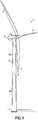
- Fig. 1 shows one example of a wind turbine 2 having a rotor 4 mounted to a nacelle 6, which is supported on a tower 8.
- the rotor 4 serves as the prime mover for an electromechanical system. Wind causes the rotor 4 to rotate, and this rotational energy is delivered to a power transmission system housed within the nacelle 6.
- the power transmission system converts the rotational energy into electrical power.
- the tower 8 shown in Fig. 1 is a tubular steel tower comprised of multiple tower sections 8a, 8b.
- the tower sections 8a, 8b are cylindrical or slightly tapered (i.e., conical) and stacked on top of each other. Again, however, this is merely an example.
- the description below focuses damping tower oscillations and may apply to any wind turbine tower that is a tall, slender structure susceptible to oscillations.
- the description may apply to steel towers having segmented tower sections, concrete towers, composite towers, hybrid towers (e.g., steel and concrete), wooden towers, etc.
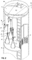
- a damping system 10 for the tower 8 is shown.
- the damping system 10 in this embodiment is installed in one of the tower sections (e.g., the uppermost tower section 8a).
- the tower section 8a includes various tower components, such as an upper platform 12, lower platform 14, and ladder 16 providing access to the upper and lower platforms 14, 16.
- the lower platform 14 is shaped to accommodate an elevator lift (not shown) and includes safety fencing 18 around the area for the elevator lift.
- the damping system 10 includes several sandbags 20 that are each suspended from a bracket 22 by a chain 24. More specifically, the sandbags 20 are each suspended from the hook of a ratchet wrench 26 (also referred to as a "ratchet chain hoist") positioned on the associated chain 24.
- the brackets 22 and sandbags 20 are distributed circumferentially about the tower section 8a in relation to a tower wall 28, as shown in Fig. 3 . Although three sandbags 20 are shown, any number of sandbags or even a single sandbag may be used in alternative embodiments. There may also be multiple sandbags suspended from the same bracket in alternative embodiments.
- the bracket 22 in this embodiment comprises a vertical support 30, horizontal support 32, and cross beam 34.
- the vertical support 30 may be mounted to a tower wall 28 using known techniques.
- the bracket 22 may be bolted or otherwise secured to magnets 34, which in turn are magnetically attached to the tower wall 28. Examples such magnets and techniques are described in WO 2003/067083 and WO 2004/099609 . Other known techniques include fastening, welding, adhesion, etc.
- a safety cable 36 or the like may connect the bracket 22 to another, permanently-installed tower component, such as the upper platform 12, thereby providing a back-up means of support in the event the bracket 22 slips along or disengages from the tower wall 28 due to ineffective mounting.
- the horizontal support 32 of the bracket 22 includes different attachment points 40 for the chain 24. This allows the sandbag 20 to be connected to the bracket 22 at different lateral distances from the tower wall 28.
- the vertical distance by which the sandbag 20 is suspended from the bracket 22 may be adjusted using the ratchet wrench 26.
- the lateral distance, vertical distance, and mass of each sandbag 20 are such that the sandbags 20 are configured to hit said tower wall 28, 56 during oscillations in said wind turbine tower, in order to damp said oscillations. It has been found that the most efficient damping is found when at least a small lateral distance is present between the sandbag and the wall, such that a small number of oscillations of the sandbag will occur prior to it hitting the wall.
- the sandbags are configured to act as pendulums that counteract a fundamental mode of vibration of the tower 8.
- the sandbags will start oscillating with a frequency corresponding to a fundamental mode of vibration of the tower for a few oscillations before taking out part of the kinetic energy in that oscillation by hitting the tower, thereby transforming the kinetic energy into heat energy through a plastic deformation of the sandbag.
- the damping system 10 has the advantage of being easy to install and remove, which provides a great amount of flexibility in terms of its use.
- the damping system 10 may be installed as a permanent fixture intended to remain in the tower 8 after the wind turbine 2 has been fully erected, or as a retrofit or temporary solution for addressing tower oscillations as they arise. The latter situation is particularly advantageous during the installation process of a wind turbine because of the challenges mentioned in the background section above.
- one method of installing the wind turbine 2 may involve using the damping system 10 during one or more stages of the installation.
- Such a method first comprises partially or completely erecting the tower 8.
- the damping system 10 may be installed in the uppermost tower section 8a before or after the tower section 8a is erected.
- the brackets 22 may be mounted to the tower wall 28 and the sandbags 20 connected to the brackets 22 prior to transporting the tower section 8a to the site of installation.
- These steps may alternatively occur after mounting the tower section 8a to the other previously-installed tower section 8b (or a foundation in embodiments where the tower 8 only comprises one tower section).
- the sandbags 20 are eventually suspended from the brackets 22 by an initial distance. This distance is adjusted by operating the ratchet wrench 26 until a desired vertical distance is attained.
- the desired vertical distance depends on the height of the tower 8, as does the desired lateral distance from the tower wall 28 (determined by the attachment point 40 of the chain 24 to the bracket 22).
- the lateral distance, vertical distance, and mass of each sandbag 20 are selected such that the sandbags 20 are configured to hit said tower wall 28, 56 during oscillations in said wind turbine tower, in order to damp said oscillations.
- the sandbags are configured to act as pendulums that counteract a fundamental mode of vibration of the tower 8. The method is particularly advantageous if the fundamental mode of vibration is the first natural frequency of bending vibration of the tower 8.
- This frequency is the most susceptible to oscillations caused by vortex shedding because of the lower wind speeds at which vortex shedding can be in resonance with the frequency.
- tuning the damping system 10 to the first natural frequency of bending vibration maximizes its effectiveness at damping oscillations caused by vortex shedding.
- the tower 8 may remain standing for an extended period of time prior to installing the nacelle 6 or its components, whose significant weight changes the dynamics of the overall structure and makes vortex shedding less of a concern.
- the logistics of installing a wind farm with several wind turbines may be optimized to make the most efficient use of resources and equipment (e.g., cranes).
- the damping system 10 is removed from the tower 8. This may be done after positioning one or more nacelle components (or even an entire nacelle with all nacelle components) on the tower 8. Alternatively, it may be done shortly before positioning the one or more nacelle components such that the tower 8 is only susceptible to oscillations caused by vortex shedding for a short period of time.
- One way in which the damping system 10 may be removed is by positioning the sandbags 20 onto the lower platform 14 (e.g., by using the ratchet wrenches 26). Each sandbag 20 is then moved from the lower platform 14 onto the elevator lift, transported toward the bottom of the tower 8 using the elevator lift, and eventually removed through a door near the bottom of the tower 8. It may be necessary to repeat these steps one or more times depending on the number of sandbags used and the capacity of the elevator lift.
- the damping system 10 may also be used earlier in the installation process, for example, when less than all of the tower sections have been erected. In that situation the damping system 10 is installed in the last tower section erected.
- the lateral distance and/or vertical distance of the sandbags 20 will be different from when the damping system 10 is used in the uppermost section of a completely-erected tower so that the damping system 10 is tuned to a natural frequency of the partially-erected tower.
- the different attachment points 40 on the brackets 22 and the ratchet wrenches 26 facilitate the ability to set these distances according to the dynamics of the structure.
- the partially-erected tower may remain standing for an extended period of time without concerns that vortex shedding will lead to significant oscillations.
- the damping system 10 may first be removed by passing the sandbags 20 through an open top end of the tower section in which they were installed. It is also possible to remove the damping system 10 in the manner described above using the elevator lift. Alternatively, if the damping system 10 is to be used in the next tower section, it may remain in the tower until the next tower section is installed and then moved accordingly. In other words, the damping system 10 may be removed from one tower section and installed in the next.
- Figs. 5-8 Various alternatives to the above-described embodiments are shown in Figs. 5-8 , where the same reference numbers are used to refer to corresponding structures.
- the brackets 22 in the above-described embodiments are merely representative tower components to which the sandbags 20 are connected via the ratchet wrenches 26 and chains 24. Other tower components may support the sandbags instead.
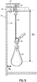
- Fig. 5 illustrates a sandbag 20 being connected to and suspended from a different type of bracket.
- the bracket shown is a beam 50 secured to a top flange 52 of a tower section 54 and extending inwardly away from a tower wall 56. Further, in fig.
- d L is the distance between the tower wall and the part of the bag closest to the tower wall
- dv is the distance between the point of contact for suspending the bag to a tower component fixed relative to to the tower wall and the center of gravity of the bag.
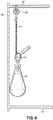
- Fig. 6 illustrates a sandbag 20 being connected to and suspended from a platform 60 (e.g., the upper platform 12 in Fig. 2 ). The connection occurs via the ratchet wrench 26 and chain 24, which is hooked onto or otherwise secured to an eye nut 62 that has been bolted to the platform 60.
- a platform 60 e.g., the upper platform 12 in Fig. 2
- the connection occurs via the ratchet wrench 26 and chain 24, which is hooked onto or otherwise secured to an eye nut 62 that has been bolted to the platform 60.
- fig. 6 illustrates how a sandbag can be mounted such that it abuts the wall when hanging freely without any oscillations of the tower.
- Fig. 7 illustrates a variation of the embodiment shown in Fig. 6 .
- the arrangement includes a frame 70 from which the chain 24 extends.
- the chain 24 may be engaged with one of several hooks 72 provided on the frame 70, which in turn is suspended from the eye nut 62 by a rope or cable 74.
- the rope 74 may be used like a sling and tied off to another tower component (not shown) after positioning the frame 70 at a desired height within the tower 8.
- the frame 70 offers the ability to suspend the sandbags at different vertical distances from the platform 60 without the need for a ratchet wrench or the like. However, ratchet wrenches may still be used if desired.
- FIG. 8 illustrates an alternative to the sandbags shown in other figures.
- a conventional bag 80 such as a tool bag, may be filled with more or less anything with a desired combined mass, such as a number of smaller sandbags 82 or other bags of liquid or material.
- the smaller bags 82 have the advantage of being easier to handle and transport compared to the sandbags 20 shown in Figs. 2-6 .
- the bag 80 is filled with a sufficient number of the smaller bags 82 to provide the desired mass.
- any bag of liquid or material may be used according to the invention.
- bag is meant in a broad sense to include any receptacle, container, or other structure that holds the liquid or material.
- sandbags are shown and described as being connected to the tower component(s) via ratchet wrenches and chains, it is also possible to use cables, ropes, or other devices.
- tower wall herein is meant in a broad sense to also include tower parts in connection with said tower wall, suitable for the purpose.
Description
- The present invention relates to wind turbines, and in particular to methods of damping oscillations in towers of wind turbines.
- A horizontal-axis wind turbine typically includes a tower, a nacelle supported by the tower, and a rotor mounted to the nacelle. Over time there has been a significant increase in the overall size of these machines and their components. This increase in size presents many challenges, both before and during operation.
- For example, wind turbine towers are tall, slender structures typically comprised of cylindrical and/or conical sections. As wind blows across the tower, vortices are shed alternately from opposite sides of the tower. This gives rise to a fluctuating force acting substantially perpendicular to the wind direction. The fluctuating force can lead to large oscillations when the periodic frequency of the vortex shedding is similar to one of the natural frequencies of the tower.
- When the nacelle is installed on a tower, vortex shedding from the wind alone (i.e., when the wind turbine is not in operation) is less of a significant concern. The fluctuating forces have a negligible effect because the massive weight of the nacelle changes the dynamic behavior of the overall structure. Prior to supporting the nacelle, however, the tower is more susceptible to oscillations from vortex shedding. As towers increase in size, lower wind speeds can produce vortex shedding in resonance with a natural frequency of the tower. Thus, large oscillations from vortex shedding become more of a concern.
-
EP 1 008 747 A2WO 2014/040598 A1 each discloses a system for damping oscillations experienced by a wind turbine tower. The system comprises a mass suspended inside the tower through. InEP 1 008 747 A2 - A method of damping oscillations in a wind turbine tower comprises connecting a bag of material (e.g., sand) or liquid to a tower component at a first lateral distance away from a tower wall. The bag is also suspended from the tower component by a first vertical distance. The height of the tower component is known such that the first vertical distance corresponds to a particular height within the tower. The first lateral distance, first vertical distance, and mass of the bag are such that the bag is configured to hit said tower wall during oscillations in said wind turbine tower, in order to damp said oscillations in said wind turbine tower. Further, in advantageous embodiments, the sandbags are configured to act as a pendulum counteracting a fundamental mode of vibration of the tower.
- This method may be used strategically during installation of the wind turbine because of its ease of use. Thus, the invention also provides a method of installing a wind turbine comprising erecting a tower of the wind turbine and installing a damping system in the tower. The damping system is installed in the manner mentioned above. That is, by connecting a bag of material or liquid to a tower component at a first lateral distance from a tower wall and suspending the bag from the tower component by a vertical distance. Again the height of the tower component is known such that the vertical distance corresponds to a particular height within the tower. The method of installation further involves damping oscillations caused by vortices shed from the tower, wherein the first lateral distance, first vertical distance, and mass of the bag are such that the bag is configured to hit said tower wall during oscillations in said wind turbine tower, in order to damp said oscillations in said wind turbine tower. Further, in advantageous embodiments, the sandbags are configured to act as a pendulum that counteracts a fundamental mode of vibration of the tower. Eventually one or more nacelle components are positioned on the tower thereby making the tower less susceptible to oscillations caused by vortex shedding. Before or after this step, the damping system is removed from the tower.
- In an embodiment of the method according to the invention the ratio between said first vertical distance and said first lateral distance is between 5 and 20, such as between 8 and 15 or between 10 and 12.
- In an embodiment of the method according to the invention the mass of said bag is between 20kg and 300kg, such as between 50kg and 200kg or between 75kg and 150kg.
- In an embodiment of the method according to the invention the first lateral distance, first vertical distance, and mass of the bag are such that the bag during oscillation will act as a pendulum counteracting a fundamental mode of vibration of the tower prior to hitting said wind turbine tower.
- In an embodiment of the method according to the invention said damping of oscillations is at least partly obtained by converting kinetic energy into heat energy through plastic deformation of said bag.
- In an embodiment of the method according to the invention the bag is connected to and suspended from the tower component with a chain, cable, or rope, and wherein suspending the bag comprises:
- suspending the bag an initial distance from the tower component; and
- adjusting the distance by which the bag is suspended from the tower component until the first vertical distance is attained.
- In an embodiment of the method according to the invention, the method further comprising:
- positioning the bag onto a platform in the tower;
- moving the bag from the platform onto an elevator lift;
- transporting the bag toward the bottom of the tower using the elevator lift; and
- removing the bag through a door in the tower.
- In an embodiment of the method according to the invention, the bag is connected to and suspending from the tower component with a chain and via a ratchet wrench positioned on the chain, and further wherein adjusting the distance by which the bag is suspended comprises operating the ratchet wrench to move the bag along the chain.
- In an embodiment of the method according to the invention, the method further comprising:
- filling the bag (80) with a plurality of smaller bags (82), wherein the smaller bags effectively provide the overall mass of the bag.
- In an embodiment of the method according to the invention, installing the damping system comprises passing the bag through an open top end of the tower or through a door of the tower after the tower is erected.
-
-
Fig. 1 is a perspective view of an example of a wind turbine. -
Fig. 2 is a perspective view of a damping system installed in a tower of the wind turbine. -
Fig. 3 is a top elevation view the damping system ofFig. 2 . -
Fig. 4 is a perspective view showing a portion of the damping system ofFig. 2 in further detail. -
Fig. 5 is a cross-sectional view of a portion of tower with a damping system installed according to an alternative embodiment. -
Fig. 6 is a cross-sectional view of a portion of tower with a damping system installed according to another alternative embodiment. -
Fig. 7 is a cross-sectional view of a portion of tower with a damping system installed according to yet another alternative embodiment. -
Fig. 8 is a perspective view of a portion of a damping system according to an alternative embodiment. -
Fig. 1 shows one example of a wind turbine 2 having arotor 4 mounted to a nacelle 6, which is supported on atower 8. Therotor 4 serves as the prime mover for an electromechanical system. Wind causes therotor 4 to rotate, and this rotational energy is delivered to a power transmission system housed within the nacelle 6. The power transmission system converts the rotational energy into electrical power. - The
tower 8 shown inFig. 1 is a tubular steel tower comprised ofmultiple tower sections 8a, 8b. Thetower sections 8a, 8b are cylindrical or slightly tapered (i.e., conical) and stacked on top of each other. Again, however, this is merely an example. The description below focuses damping tower oscillations and may apply to any wind turbine tower that is a tall, slender structure susceptible to oscillations. For example, the description may apply to steel towers having segmented tower sections, concrete towers, composite towers, hybrid towers (e.g., steel and concrete), wooden towers, etc. - With this in mind, and now referring to
Fig. 2 , one embodiment of a dampingsystem 10 for thetower 8 is shown. The dampingsystem 10 in this embodiment is installed in one of the tower sections (e.g., theuppermost tower section 8a). The installation process of the dampingsystem 10 and its context within the overall installation of the wind turbine 2 will be described in further detail below. As shown inFig. 2 , thetower section 8a includes various tower components, such as an upper platform 12,lower platform 14, andladder 16 providing access to the upper andlower platforms lower platform 14 is shaped to accommodate an elevator lift (not shown) and includessafety fencing 18 around the area for the elevator lift. - The damping
system 10 includesseveral sandbags 20 that are each suspended from abracket 22 by achain 24. More specifically, thesandbags 20 are each suspended from the hook of a ratchet wrench 26 (also referred to as a "ratchet chain hoist") positioned on the associatedchain 24. Thebrackets 22 andsandbags 20 are distributed circumferentially about thetower section 8a in relation to atower wall 28, as shown inFig. 3 . Although threesandbags 20 are shown, any number of sandbags or even a single sandbag may be used in alternative embodiments. There may also be multiple sandbags suspended from the same bracket in alternative embodiments. - One of the
brackets 22 and one of thesandbags 20 are shown in greater detail inFig. 4 . Thebracket 22 in this embodiment comprises avertical support 30,horizontal support 32, and crossbeam 34. Thevertical support 30 may be mounted to atower wall 28 using known techniques. For example, thebracket 22 may be bolted or otherwise secured tomagnets 34, which in turn are magnetically attached to thetower wall 28. Examples such magnets and techniques are described inWO 2003/067083 andWO 2004/099609 . Other known techniques include fastening, welding, adhesion, etc. Asafety cable 36 or the like may connect thebracket 22 to another, permanently-installed tower component, such as the upper platform 12, thereby providing a back-up means of support in the event thebracket 22 slips along or disengages from thetower wall 28 due to ineffective mounting. - The
horizontal support 32 of thebracket 22 includes different attachment points 40 for thechain 24. This allows thesandbag 20 to be connected to thebracket 22 at different lateral distances from thetower wall 28. The vertical distance by which thesandbag 20 is suspended from thebracket 22 may be adjusted using theratchet wrench 26. The lateral distance, vertical distance, and mass of eachsandbag 20 are such that thesandbags 20 are configured to hit saidtower wall 28, 56 during oscillations in said wind turbine tower, in order to damp said oscillations. It has been found that the most efficient damping is found when at least a small lateral distance is present between the sandbag and the wall, such that a small number of oscillations of the sandbag will occur prior to it hitting the wall. This small number may typically be below 10, such as about 5. Further, in advantageous embodiments, the sandbags are configured to act as pendulums that counteract a fundamental mode of vibration of thetower 8. Hereby, upon oscillation of the tower due to vortex shedding, the sandbags will start oscillating with a frequency corresponding to a fundamental mode of vibration of the tower for a few oscillations before taking out part of the kinetic energy in that oscillation by hitting the tower, thereby transforming the kinetic energy into heat energy through a plastic deformation of the sandbag. - The damping
system 10 has the advantage of being easy to install and remove, which provides a great amount of flexibility in terms of its use. For example, the dampingsystem 10 may be installed as a permanent fixture intended to remain in thetower 8 after the wind turbine 2 has been fully erected, or as a retrofit or temporary solution for addressing tower oscillations as they arise. The latter situation is particularly advantageous during the installation process of a wind turbine because of the challenges mentioned in the background section above. - Accordingly, one method of installing the wind turbine 2 may involve using the damping
system 10 during one or more stages of the installation. Such a method first comprises partially or completely erecting thetower 8. Assuming the latter situation with thetower 8 being that shown inFigs. 1 and2 , the dampingsystem 10 may be installed in theuppermost tower section 8a before or after thetower section 8a is erected. For example, thebrackets 22 may be mounted to thetower wall 28 and thesandbags 20 connected to thebrackets 22 prior to transporting thetower section 8a to the site of installation. These steps may alternatively occur after mounting thetower section 8a to the other previously-installed tower section 8b (or a foundation in embodiments where thetower 8 only comprises one tower section). Either way, thesandbags 20 are eventually suspended from thebrackets 22 by an initial distance. This distance is adjusted by operating theratchet wrench 26 until a desired vertical distance is attained. - The desired vertical distance depends on the height of the
tower 8, as does the desired lateral distance from the tower wall 28 (determined by theattachment point 40 of thechain 24 to the bracket 22). Again, the lateral distance, vertical distance, and mass of eachsandbag 20 are selected such that thesandbags 20 are configured to hit saidtower wall 28, 56 during oscillations in said wind turbine tower, in order to damp said oscillations. Further, in advantageous embodiments, the sandbags are configured to act as pendulums that counteract a fundamental mode of vibration of thetower 8. The method is particularly advantageous if the fundamental mode of vibration is the first natural frequency of bending vibration of thetower 8. This frequency is the most susceptible to oscillations caused by vortex shedding because of the lower wind speeds at which vortex shedding can be in resonance with the frequency. Thus, tuning the dampingsystem 10 to the first natural frequency of bending vibration maximizes its effectiveness at damping oscillations caused by vortex shedding. Thetower 8 may remain standing for an extended period of time prior to installing the nacelle 6 or its components, whose significant weight changes the dynamics of the overall structure and makes vortex shedding less of a concern. The logistics of installing a wind farm with several wind turbines may be optimized to make the most efficient use of resources and equipment (e.g., cranes). - Eventually the damping
system 10 is removed from thetower 8. This may be done after positioning one or more nacelle components (or even an entire nacelle with all nacelle components) on thetower 8. Alternatively, it may be done shortly before positioning the one or more nacelle components such that thetower 8 is only susceptible to oscillations caused by vortex shedding for a short period of time. One way in which the dampingsystem 10 may be removed is by positioning thesandbags 20 onto the lower platform 14 (e.g., by using the ratchet wrenches 26). Eachsandbag 20 is then moved from thelower platform 14 onto the elevator lift, transported toward the bottom of thetower 8 using the elevator lift, and eventually removed through a door near the bottom of thetower 8. It may be necessary to repeat these steps one or more times depending on the number of sandbags used and the capacity of the elevator lift. - The damping
system 10 may also be used earlier in the installation process, for example, when less than all of the tower sections have been erected. In that situation the dampingsystem 10 is installed in the last tower section erected. The lateral distance and/or vertical distance of thesandbags 20 will be different from when the dampingsystem 10 is used in the uppermost section of a completely-erected tower so that the dampingsystem 10 is tuned to a natural frequency of the partially-erected tower. The different attachment points 40 on thebrackets 22 and the ratchet wrenches 26 facilitate the ability to set these distances according to the dynamics of the structure. - As can be appreciated, the partially-erected tower may remain standing for an extended period of time without concerns that vortex shedding will lead to significant oscillations. When the next tower section is going to be installed to continue or complete the erection of the tower, the damping
system 10 may first be removed by passing thesandbags 20 through an open top end of the tower section in which they were installed. It is also possible to remove the dampingsystem 10 in the manner described above using the elevator lift. Alternatively, if the dampingsystem 10 is to be used in the next tower section, it may remain in the tower until the next tower section is installed and then moved accordingly. In other words, the dampingsystem 10 may be removed from one tower section and installed in the next. - Various alternatives to the above-described embodiments are shown in
Figs. 5-8 , where the same reference numbers are used to refer to corresponding structures. As will be appreciated, thebrackets 22 in the above-described embodiments are merely representative tower components to which thesandbags 20 are connected via the ratchet wrenches 26 andchains 24. Other tower components may support the sandbags instead. For example,Fig. 5 illustrates asandbag 20 being connected to and suspended from a different type of bracket. The bracket shown is a beam 50 secured to atop flange 52 of atower section 54 and extending inwardly away from a tower wall 56. Further, infig. 5 is illustrated how the lateral (dL) and vertical (dv) distances as mentioned herein are understood. dL is the distance between the tower wall and the part of the bag closest to the tower wall, whereas dv is the distance between the point of contact for suspending the bag to a tower component fixed relative to to the tower wall and the center of gravity of the bag. -
Fig. 6 illustrates asandbag 20 being connected to and suspended from a platform 60 (e.g., the upper platform 12 inFig. 2 ). The connection occurs via theratchet wrench 26 andchain 24, which is hooked onto or otherwise secured to aneye nut 62 that has been bolted to theplatform 60. However, skilled persons will appreciate other ways of connecting and suspending thesandbags 20. Further,fig. 6 illustrates how a sandbag can be mounted such that it abuts the wall when hanging freely without any oscillations of the tower. This solution can be used to dampen tower oscillations as well; however as the sandbag will only carry out one half oscillation each time before hitting the wall, the damping of the tower oscillations is believed to be better with a small lateral distance between the sandbag and the tower wall as described above. -
Fig. 7 illustrates a variation of the embodiment shown inFig. 6 . Rather than securing thechain 24 directly to aneye nut 62, the arrangement includes aframe 70 from which thechain 24 extends. Thechain 24 may be engaged with one ofseveral hooks 72 provided on theframe 70, which in turn is suspended from theeye nut 62 by a rope orcable 74. Therope 74 may be used like a sling and tied off to another tower component (not shown) after positioning theframe 70 at a desired height within thetower 8. With thehooks 72 positioned at different vertical distances, theframe 70 offers the ability to suspend the sandbags at different vertical distances from theplatform 60 without the need for a ratchet wrench or the like. However, ratchet wrenches may still be used if desired. - Finally,
Fig. 8 illustrates an alternative to the sandbags shown in other figures. Aconventional bag 80, such as a tool bag, may be filled with more or less anything with a desired combined mass, such as a number ofsmaller sandbags 82 or other bags of liquid or material. Thesmaller bags 82 have the advantage of being easier to handle and transport compared to thesandbags 20 shown inFigs. 2-6 . Thebag 80 is filled with a sufficient number of thesmaller bags 82 to provide the desired mass. - The embodiments described above are merely examples of the invention defined by the claims that appear below. Those skilled in the art will appreciate additional examples, modifications, and advantages based on the description. For example, although sandbags are shown and described above, any bag of liquid or material may be used according to the invention. The term "bag" is meant in a broad sense to include any receptacle, container, or other structure that holds the liquid or material. And although the sandbags are shown and described as being connected to the tower component(s) via ratchet wrenches and chains, it is also possible to use cables, ropes, or other devices. The term "tower wall" herein is meant in a broad sense to also include tower parts in connection with said tower wall, suitable for the purpose. Thus, the details of any particular embodiment should not be seen to necessarily limit the scope of the claims below. In addition to appreciating other modifications and variations, skilled persons will understand how features of the various embodiments may be combined in different ways.
Claims (19)
- A method of damping oscillations in a wind turbine tower (8), comprising:suspending a bag (20, 80) of material or liquid from a tower component such that the bag is configured to hit a tower wall (28, 56) of said wind turbine tower during oscillations in said wind turbine tower, in order to damp said oscillations in said wind turbine tower.
- A method according to claim 1, comprising:connecting a bag of material or liquid to a tower component at a first lateral distance (dL) away from a tower wall;suspending the bag from the tower component by a first vertical distance (dv), wherein the height of the tower component is known such that the first vertical distance corresponds to a particular height within the tower, and further wherein the first lateral distance, first vertical distance, and mass of the bag are such that the bag is configured to hit said tower wall during oscillations in said wind turbine tower, in order to damp said oscillations in said wind turbine tower.
- A method according to any preceding claim, further comprising:mounting a bracket (22) to the tower, the bracket extending away from tower wall and serving as the tower component to which the bag is connected.
- A method according to claim 3, wherein mounting the bracket to the tower comprises securing the brackets to the tower wall without welding.
- A method according to claim 3 or 4, wherein mounting the bracket to the tower comprises securing the bracket to a flange of the tower.
- A method according to any preceding claim, wherein the bag is connected to and suspended from a platform in the tower.
- A method according to any preceding claim, further comprising:providing a plurality of bags of material or liquid; andconnecting and suspending the bags to a common tower component or respective tower components in the manner provided by any preceding claim, wherein at least some of the bags are distributed circumferentially in relation to the tower wall.
- A system for damping oscillations experienced by a wind turbine tower (8), comprising:one or more bags (20, 80) of material or liquid;one or more tower components configured to be secured to the tower; andone or more chains (24), cables, or ropes (74) configured to suspend the one or more bags from the one or more tower components, characterized in that said system is configured such that upon installation in a wind turbine tower, the bag is configured to hit a tower wall (28, 56) of said wind turbine tower during oscillations in said wind turbine tower, in order to damp said oscillations in said wind turbine tower.
- A system according to claim 8, wherein said bag is connected to said one or more tower components at a first lateral distance (dL) away from a tower wall;
wherein said bag is suspended from the tower component by a first vertical distance (dv), wherein the height of the tower component is known such that the first vertical distance corresponds to a particular height within the tower, and further wherein the first lateral distance, first vertical distance, and mass of the bag are such that the bag is configured to hit said tower wall during oscillations in said wind turbine tower, in order to damp said oscillations in said wind turbine tower. - A system according to claim 9, wherein the ratio between said first vertical distance and said first lateral distance is between 5 and 20, such as between 8 and 15 or between 10 and 12.
- A system according to any of the claims 8-10, wherein the mass of said bag is between 20kg and 300kg, such as between 50kg and 200kg or between 75kg and 150kg.
- A system according to any of the claims 9-11, wherein the first lateral distance, first vertical distance, and mass of the bag are such that the bag during oscillation will act as a pendulum counteracting a fundamental mode of vibration of the tower prior to hitting said wind turbine tower.
- A system according to any of the claims 8-12, wherein the one or more tower components have multiple attachment points for the chains, cables, or ropes so that the bags can be positioned at different lateral distances from a wall of the wind turbine tower.
- A system according to any of the claims 8-13, wherein each bag comprises at least one large bag filled with a number of smaller bags containing the material or liquid.
- A wind turbine comprising a system according to any of the claims 8-14.
- A method of installing a wind turbine (2), comprising:erecting a tower (8) of the wind turbine;installing a damping system (10) according to any of the claims 8-14 in the tower;positioning one or more nacelle components on the tower thereby making the tower less susceptible to oscillations caused by vortex shedding; andremoving the damping system from the tower prior to start-up of the wind turbine.
- A method according to claim 16, wherein the tower comprises multiple tower sections, and further wherein erecting the tower comprises erecting less than all of the tower sections, the damping system being used to dampen oscillations of the partially-erected tower, the method further comprising:erecting another tower section to continue or complete the erection of the tower.
- A method according to claim 17, wherein the installing and damping steps of claim 16 are repeated after erecting the another tower section, the bag being connected to the tower component at a second lateral distance and suspended from a tower component by a second vertical distance when the installing and damping steps are repeated.
- A method according to any of claims 16-18, wherein installing the damping system further comprises:installing the tower component in a tower section before the tower section is erected as part of the tower.
Applications Claiming Priority (2)
| Application Number | Priority Date | Filing Date | Title |
|---|---|---|---|
| DKPA201370627A DK201370627A1 (en) | 2013-10-28 | 2013-10-28 | Method of damping wind turbine tower oscillations |
| PCT/DK2014/050340 WO2015062608A1 (en) | 2013-10-28 | 2014-10-20 | Method of damping wind turbine tower oscillations |
Publications (2)
| Publication Number | Publication Date |
|---|---|
| EP3063405A1 EP3063405A1 (en) | 2016-09-07 |
| EP3063405B1 true EP3063405B1 (en) | 2018-02-28 |
Family
ID=51794703
Family Applications (1)
| Application Number | Title | Priority Date | Filing Date |
|---|---|---|---|
| EP14789156.8A Active EP3063405B1 (en) | 2013-10-28 | 2014-10-20 | Method of damping wind turbine tower oscillations |
Country Status (6)
| Country | Link |
|---|---|
| US (1) | US9683556B2 (en) |
| EP (1) | EP3063405B1 (en) |
| CN (1) | CN105745439B (en) |
| DK (1) | DK201370627A1 (en) |
| ES (1) | ES2669431T3 (en) |
| WO (1) | WO2015062608A1 (en) |
Families Citing this family (28)
| Publication number | Priority date | Publication date | Assignee | Title |
|---|---|---|---|---|
| DK201370627A1 (en) * | 2013-10-28 | 2015-05-11 | Vestas Wind Sys As | Method of damping wind turbine tower oscillations |
| DE102015013098A1 (en) * | 2015-10-12 | 2017-04-13 | Senvion Gmbh | Method for installing a pendulum damper in a wind turbine, filling system and wind turbine |
| CN105220791B (en) * | 2015-11-18 | 2017-07-28 | 山东大学 | Multidimensional dual adjustable formula damping control device |
| EP3269997B1 (en) * | 2016-07-14 | 2020-01-01 | Siemens Gamesa Renewable Energy A/S | Oscillation absorber for a structure |
| ES2947638T3 (en) * | 2016-09-27 | 2023-08-14 | Vestas Wind Sys As | Tower Vibration Damper |
| WO2018153416A1 (en) * | 2017-02-21 | 2018-08-30 | Vestas Wind Systems A/S | Tower vibration damper |
| CN107013418A (en) * | 2017-05-02 | 2017-08-04 | 沈阳建筑大学 | A kind of mechanical device for suppressing Large-scale Wind Turbines resonance |
| EP3415786B1 (en) * | 2017-06-13 | 2021-10-20 | GE Renewable Technologies Wind B.V. | Tuned mass dampers for damping an oscillating movement of a structure |
| EP3450644A1 (en) * | 2017-08-29 | 2019-03-06 | GE Renewable Technologies Wind B.V. | Arrangements and methods for damping oscillations in structures |
| EP3450752B1 (en) * | 2017-09-04 | 2020-06-17 | Siemens Gamesa Renewable Energy A/S | Wind turbine having an access arrangement for a nacelle |
| KR102524595B1 (en) * | 2017-09-04 | 2023-04-21 | 베스타스 윈드 시스템스 에이/에스 | tower vibration damper |
| CN108443396A (en) * | 2018-01-15 | 2018-08-24 | 广东工业大学 | A kind of wind turbine TMD dampers damping device and its installation method |
| CN108443084A (en) * | 2018-05-22 | 2018-08-24 | 中国电建集团中南勘测设计研究院有限公司 | A kind of construction method of damper mechanism, blower fan tower barrel and blower fan tower barrel |
| CN108843522B (en) * | 2018-06-07 | 2019-07-26 | 北京金风科创风电设备有限公司 | Damper limiting device, tower barrel and wind generating set |
| US11346324B2 (en) * | 2018-06-29 | 2022-05-31 | Vestas Wind Systems A/S | Method of erecting a wind turbine |
| WO2020001719A1 (en) * | 2018-06-29 | 2020-01-02 | Vestas Wind Systems A/S | Damper unit for a tower structure |
| KR20210025099A (en) * | 2018-06-29 | 2021-03-08 | 엠에이치아이 베스타스 오프쇼어 윈드 에이/에스 | Tower damper |
| ES2739898A1 (en) | 2018-08-03 | 2020-02-04 | Siemens Gamesa Renewable Energy Innovation & Technology SL | Wind turbine tower system for modifying the second natural frequency (Machine-translation by Google Translate, not legally binding) |
| CN112805468A (en) * | 2018-10-09 | 2021-05-14 | 安利马克集团管理公司 | Tower comprising a mast |
| EP3643595A1 (en) * | 2018-10-23 | 2020-04-29 | Siemens Gamesa Renewable Energy A/S | Gyro for stabilizing wind turbine movements |
| CN113227569B (en) * | 2018-12-20 | 2023-08-22 | 维斯塔斯风力系统有限公司 | Modular Tower Damper System |
| WO2020224740A1 (en) * | 2019-05-06 | 2020-11-12 | Vestas Wind Systems A/S | Vibration damping of a structure |
| CN111350630B (en) * | 2020-03-08 | 2021-06-04 | 北京工业大学 | Multi-wind wheel multi-directional energy collection type wind power generator tower adopting multi-dimensional vibration damper |
| WO2021259518A1 (en) * | 2020-06-24 | 2021-12-30 | Fm Energie Gmbh & Co.Kg | Reversible suspension for a vibration damper in the construction and disassembly of a wind turbine |
| EP4202221A1 (en) * | 2021-12-22 | 2023-06-28 | Comercial Química Massó S.A. | Damper for wind turbines |
| ES2955376A1 (en) * | 2022-04-26 | 2023-11-30 | Setga S L U | AUXILIARY DEVICE TO INCREASE DAMPING IN LIGHT MASTS (Machine-translation by Google Translate, not legally binding) |
| WO2024008254A1 (en) * | 2022-07-08 | 2024-01-11 | Vestas Wind Systems A/S | Vibration damper for a wind turbine, tower structure with a vibration damper, and method of damping vibrations |
| WO2024008255A1 (en) * | 2022-07-08 | 2024-01-11 | Vestas Wind Systems A/S | Wind turbines having dampers with tilt mechanisms and methods of damping vibrations in wind turbines |
Family Cites Families (13)
| Publication number | Priority date | Publication date | Assignee | Title |
|---|---|---|---|---|
| DE19856500B4 (en) * | 1998-12-08 | 2005-12-08 | Franz Mitsch | vibration absorber |
| JP2003176774A (en) * | 2001-12-10 | 2003-06-27 | Kyowa Engineering Consultants Co Ltd | Wind power generation device |
| US7931438B2 (en) * | 2006-12-13 | 2011-04-26 | General Electric Company | Active tower damper |
| GB0716733D0 (en) * | 2007-08-30 | 2007-10-10 | Reactec Ltd | Tower |
| ES2366141T3 (en) * | 2007-11-28 | 2011-10-17 | Vestas Wind Systems A/S | PROCEDURE TO CUSH THE SWINGS OF A WIND TURBINE. |
| KR20110077629A (en) * | 2009-12-30 | 2011-07-07 | 재단법인 포항산업과학연구원 | Wind turbine tower |
| DE102010015160B4 (en) * | 2010-04-16 | 2012-02-23 | Wölfel Beratende Ingenieure GmbH & Co. KG | Tower vibration damper for a wind turbine and wind turbine |
| KR101255502B1 (en) * | 2010-12-27 | 2013-04-16 | 미츠비시 쥬고교 가부시키가이샤 | Vibration damping device of windmill for wind power generation and windmill for wind power generation |
| CN102893052A (en) * | 2011-04-22 | 2013-01-23 | 三菱重工业株式会社 | Vibration-damping device, wind turbine device, and vibration-damping method |
| EP2895741A1 (en) * | 2012-09-17 | 2015-07-22 | Vestas Wind Systems A/S | Method of damping wind turbine tower oscillations |
| CN102936926B (en) * | 2012-10-29 | 2015-08-19 | 广东电网公司电力科学研究院 | A kind of multidimensional energy by collision quality pendulum damper |
| EP3008335A1 (en) * | 2013-06-11 | 2016-04-20 | Vestas Wind Systems A/S | Wind turbine tower having a damper |
| DK201370627A1 (en) * | 2013-10-28 | 2015-05-11 | Vestas Wind Sys As | Method of damping wind turbine tower oscillations |
-
2013
- 2013-10-28 DK DKPA201370627A patent/DK201370627A1/en not_active Application Discontinuation
-
2014
- 2014-10-20 ES ES14789156.8T patent/ES2669431T3/en active Active
- 2014-10-20 WO PCT/DK2014/050340 patent/WO2015062608A1/en active Application Filing
- 2014-10-20 CN CN201480059013.4A patent/CN105745439B/en active Active
- 2014-10-20 EP EP14789156.8A patent/EP3063405B1/en active Active
- 2014-10-20 US US15/032,918 patent/US9683556B2/en active Active
Also Published As
| Publication number | Publication date |
|---|---|
| US9683556B2 (en) | 2017-06-20 |
| US20160252079A1 (en) | 2016-09-01 |
| CN105745439B (en) | 2019-11-15 |
| EP3063405A1 (en) | 2016-09-07 |
| DK201370627A1 (en) | 2015-05-11 |
| ES2669431T3 (en) | 2018-05-25 |
| CN105745439A (en) | 2016-07-06 |
| WO2015062608A1 (en) | 2015-05-07 |
Similar Documents
| Publication | Publication Date | Title |
|---|---|---|
| EP3063405B1 (en) | Method of damping wind turbine tower oscillations | |
| EP2895741A1 (en) | Method of damping wind turbine tower oscillations | |
| US9896310B2 (en) | Load-handling means for a tower or a tower section of a wind turbine and method for erecting a wind turbine | |
| CN112368478B (en) | Method of Erecting a Wind Turbine | |
| CN105822507B (en) | For building the method and wind power plant of wind power plant | |
| US11365714B2 (en) | Methods for mounting or dismounting a wind turbine component of a multirotor wind turbine | |
| US10934999B2 (en) | Methods for mounting or dismounting wind turbine components of a multirotor wind turbine | |
| CN101484699A (en) | Wind turbine tower and a control system and method for altering the eigenfrequency of a wind turbine tower | |
| EP2584190A2 (en) | Hoisting Nacelle and Tower | |
| CN107461302A (en) | Envelope structure with external surface having function of inhibiting vortex excitation vibration | |
| KR102360544B1 (en) | Flange frames and assembly sets, and methods for pre-assembly and/or transport and/or assembly of tower segments for wind turbines | |
| US11754050B2 (en) | Modular tower damper system | |
| CN207406437U (en) | Tower and wind power generating set | |
| EP4140932A1 (en) | Climbing crane for erecting a wind turbine and method for erecting a wind turbine with a climbing crane | |
| KR101358213B1 (en) | Tower support structure and method for constructing the structure | |
| WO2012089916A1 (en) | Method and apparatus for mounting a wind power plant in a high base structure | |
| WO2010083837A2 (en) | A gripping apparatus for handling and/or servicing components of a wind turbine, and a method and a wind turbine tower therefore |
Legal Events
| Date | Code | Title | Description |
|---|---|---|---|
| PUAI | Public reference made under article 153(3) epc to a published international application that has entered the european phase |
Free format text: ORIGINAL CODE: 0009012 |
|
| 17P | Request for examination filed |
Effective date: 20160519 |
|
| AK | Designated contracting states |
Kind code of ref document: A1 Designated state(s): AL AT BE BG CH CY CZ DE DK EE ES FI FR GB GR HR HU IE IS IT LI LT LU LV MC MK MT NL NO PL PT RO RS SE SI SK SM TR |
|
| AX | Request for extension of the european patent |
Extension state: BA ME |
|
| DAX | Request for extension of the european patent (deleted) | ||
| RIC1 | Information provided on ipc code assigned before grant |
Ipc: F03D 13/00 20160101AFI20170726BHEP Ipc: F03D 80/80 20160101ALI20170726BHEP |
|
| GRAP | Despatch of communication of intention to grant a patent |
Free format text: ORIGINAL CODE: EPIDOSNIGR1 |
|
| INTG | Intention to grant announced |
Effective date: 20170914 |
|
| GRAS | Grant fee paid |
Free format text: ORIGINAL CODE: EPIDOSNIGR3 |
|
| GRAA | (expected) grant |
Free format text: ORIGINAL CODE: 0009210 |
|
| AK | Designated contracting states |
Kind code of ref document: B1 Designated state(s): AL AT BE BG CH CY CZ DE DK EE ES FI FR GB GR HR HU IE IS IT LI LT LU LV MC MK MT NL NO PL PT RO RS SE SI SK SM TR |
|
| REG | Reference to a national code |
Ref country code: GB Ref legal event code: FG4D Ref country code: CH Ref legal event code: EP |
|
| REG | Reference to a national code |
Ref country code: AT Ref legal event code: REF Ref document number: 974461 Country of ref document: AT Kind code of ref document: T Effective date: 20180315 |
|
| REG | Reference to a national code |
Ref country code: IE Ref legal event code: FG4D |
|
| REG | Reference to a national code |
Ref country code: DE Ref legal event code: R096 Ref document number: 602014021703 Country of ref document: DE |
|
| REG | Reference to a national code |
Ref country code: ES Ref legal event code: FG2A Ref document number: 2669431 Country of ref document: ES Kind code of ref document: T3 Effective date: 20180525 |
|
| REG | Reference to a national code |
Ref country code: NL Ref legal event code: MP Effective date: 20180228 |
|
| REG | Reference to a national code |
Ref country code: LT Ref legal event code: MG4D |
|
| REG | Reference to a national code |
Ref country code: AT Ref legal event code: MK05 Ref document number: 974461 Country of ref document: AT Kind code of ref document: T Effective date: 20180228 |
|
| PG25 | Lapsed in a contracting state [announced via postgrant information from national office to epo] |
Ref country code: NL Free format text: LAPSE BECAUSE OF FAILURE TO SUBMIT A TRANSLATION OF THE DESCRIPTION OR TO PAY THE FEE WITHIN THE PRESCRIBED TIME-LIMIT Effective date: 20180228 Ref country code: LT Free format text: LAPSE BECAUSE OF FAILURE TO SUBMIT A TRANSLATION OF THE DESCRIPTION OR TO PAY THE FEE WITHIN THE PRESCRIBED TIME-LIMIT Effective date: 20180228 Ref country code: HR Free format text: LAPSE BECAUSE OF FAILURE TO SUBMIT A TRANSLATION OF THE DESCRIPTION OR TO PAY THE FEE WITHIN THE PRESCRIBED TIME-LIMIT Effective date: 20180228 Ref country code: NO Free format text: LAPSE BECAUSE OF FAILURE TO SUBMIT A TRANSLATION OF THE DESCRIPTION OR TO PAY THE FEE WITHIN THE PRESCRIBED TIME-LIMIT Effective date: 20180528 Ref country code: FI Free format text: LAPSE BECAUSE OF FAILURE TO SUBMIT A TRANSLATION OF THE DESCRIPTION OR TO PAY THE FEE WITHIN THE PRESCRIBED TIME-LIMIT Effective date: 20180228 Ref country code: CY Free format text: LAPSE BECAUSE OF FAILURE TO SUBMIT A TRANSLATION OF THE DESCRIPTION OR TO PAY THE FEE WITHIN THE PRESCRIBED TIME-LIMIT Effective date: 20180228 |
|
| PG25 | Lapsed in a contracting state [announced via postgrant information from national office to epo] |
Ref country code: SE Free format text: LAPSE BECAUSE OF FAILURE TO SUBMIT A TRANSLATION OF THE DESCRIPTION OR TO PAY THE FEE WITHIN THE PRESCRIBED TIME-LIMIT Effective date: 20180228 Ref country code: LV Free format text: LAPSE BECAUSE OF FAILURE TO SUBMIT A TRANSLATION OF THE DESCRIPTION OR TO PAY THE FEE WITHIN THE PRESCRIBED TIME-LIMIT Effective date: 20180228 Ref country code: GR Free format text: LAPSE BECAUSE OF FAILURE TO SUBMIT A TRANSLATION OF THE DESCRIPTION OR TO PAY THE FEE WITHIN THE PRESCRIBED TIME-LIMIT Effective date: 20180529 Ref country code: BG Free format text: LAPSE BECAUSE OF FAILURE TO SUBMIT A TRANSLATION OF THE DESCRIPTION OR TO PAY THE FEE WITHIN THE PRESCRIBED TIME-LIMIT Effective date: 20180528 Ref country code: RS Free format text: LAPSE BECAUSE OF FAILURE TO SUBMIT A TRANSLATION OF THE DESCRIPTION OR TO PAY THE FEE WITHIN THE PRESCRIBED TIME-LIMIT Effective date: 20180228 Ref country code: AT Free format text: LAPSE BECAUSE OF FAILURE TO SUBMIT A TRANSLATION OF THE DESCRIPTION OR TO PAY THE FEE WITHIN THE PRESCRIBED TIME-LIMIT Effective date: 20180228 |
|
| REG | Reference to a national code |
Ref country code: FR Ref legal event code: PLFP Year of fee payment: 5 |
|
| PG25 | Lapsed in a contracting state [announced via postgrant information from national office to epo] |
Ref country code: IT Free format text: LAPSE BECAUSE OF FAILURE TO SUBMIT A TRANSLATION OF THE DESCRIPTION OR TO PAY THE FEE WITHIN THE PRESCRIBED TIME-LIMIT Effective date: 20180228 Ref country code: RO Free format text: LAPSE BECAUSE OF FAILURE TO SUBMIT A TRANSLATION OF THE DESCRIPTION OR TO PAY THE FEE WITHIN THE PRESCRIBED TIME-LIMIT Effective date: 20180228 Ref country code: AL Free format text: LAPSE BECAUSE OF FAILURE TO SUBMIT A TRANSLATION OF THE DESCRIPTION OR TO PAY THE FEE WITHIN THE PRESCRIBED TIME-LIMIT Effective date: 20180228 Ref country code: PL Free format text: LAPSE BECAUSE OF FAILURE TO SUBMIT A TRANSLATION OF THE DESCRIPTION OR TO PAY THE FEE WITHIN THE PRESCRIBED TIME-LIMIT Effective date: 20180228 Ref country code: EE Free format text: LAPSE BECAUSE OF FAILURE TO SUBMIT A TRANSLATION OF THE DESCRIPTION OR TO PAY THE FEE WITHIN THE PRESCRIBED TIME-LIMIT Effective date: 20180228 |
|
| REG | Reference to a national code |
Ref country code: DE Ref legal event code: R097 Ref document number: 602014021703 Country of ref document: DE |
|
| PG25 | Lapsed in a contracting state [announced via postgrant information from national office to epo] |
Ref country code: SM Free format text: LAPSE BECAUSE OF FAILURE TO SUBMIT A TRANSLATION OF THE DESCRIPTION OR TO PAY THE FEE WITHIN THE PRESCRIBED TIME-LIMIT Effective date: 20180228 Ref country code: CZ Free format text: LAPSE BECAUSE OF FAILURE TO SUBMIT A TRANSLATION OF THE DESCRIPTION OR TO PAY THE FEE WITHIN THE PRESCRIBED TIME-LIMIT Effective date: 20180228 Ref country code: SK Free format text: LAPSE BECAUSE OF FAILURE TO SUBMIT A TRANSLATION OF THE DESCRIPTION OR TO PAY THE FEE WITHIN THE PRESCRIBED TIME-LIMIT Effective date: 20180228 Ref country code: DK Free format text: LAPSE BECAUSE OF FAILURE TO SUBMIT A TRANSLATION OF THE DESCRIPTION OR TO PAY THE FEE WITHIN THE PRESCRIBED TIME-LIMIT Effective date: 20180228 |
|
| PLBE | No opposition filed within time limit |
Free format text: ORIGINAL CODE: 0009261 |
|
| STAA | Information on the status of an ep patent application or granted ep patent |
Free format text: STATUS: NO OPPOSITION FILED WITHIN TIME LIMIT |
|
| 26N | No opposition filed |
Effective date: 20181129 |
|
| PG25 | Lapsed in a contracting state [announced via postgrant information from national office to epo] |
Ref country code: SI Free format text: LAPSE BECAUSE OF FAILURE TO SUBMIT A TRANSLATION OF THE DESCRIPTION OR TO PAY THE FEE WITHIN THE PRESCRIBED TIME-LIMIT Effective date: 20180228 |
|
| REG | Reference to a national code |
Ref country code: CH Ref legal event code: PL |
|
| REG | Reference to a national code |
Ref country code: BE Ref legal event code: MM Effective date: 20181031 |
|
| PG25 | Lapsed in a contracting state [announced via postgrant information from national office to epo] |
Ref country code: MC Free format text: LAPSE BECAUSE OF FAILURE TO SUBMIT A TRANSLATION OF THE DESCRIPTION OR TO PAY THE FEE WITHIN THE PRESCRIBED TIME-LIMIT Effective date: 20180228 Ref country code: LU Free format text: LAPSE BECAUSE OF NON-PAYMENT OF DUE FEES Effective date: 20181020 |
|
| REG | Reference to a national code |
Ref country code: IE Ref legal event code: MM4A |
|
| PG25 | Lapsed in a contracting state [announced via postgrant information from national office to epo] |
Ref country code: CH Free format text: LAPSE BECAUSE OF NON-PAYMENT OF DUE FEES Effective date: 20181031 Ref country code: LI Free format text: LAPSE BECAUSE OF NON-PAYMENT OF DUE FEES Effective date: 20181031 Ref country code: BE Free format text: LAPSE BECAUSE OF NON-PAYMENT OF DUE FEES Effective date: 20181031 |
|
| PG25 | Lapsed in a contracting state [announced via postgrant information from national office to epo] |
Ref country code: IE Free format text: LAPSE BECAUSE OF NON-PAYMENT OF DUE FEES Effective date: 20181020 |
|
| PG25 | Lapsed in a contracting state [announced via postgrant information from national office to epo] |
Ref country code: MT Free format text: LAPSE BECAUSE OF NON-PAYMENT OF DUE FEES Effective date: 20181020 |
|
| PG25 | Lapsed in a contracting state [announced via postgrant information from national office to epo] |
Ref country code: TR Free format text: LAPSE BECAUSE OF FAILURE TO SUBMIT A TRANSLATION OF THE DESCRIPTION OR TO PAY THE FEE WITHIN THE PRESCRIBED TIME-LIMIT Effective date: 20180228 |
|
| PG25 | Lapsed in a contracting state [announced via postgrant information from national office to epo] |
Ref country code: PT Free format text: LAPSE BECAUSE OF FAILURE TO SUBMIT A TRANSLATION OF THE DESCRIPTION OR TO PAY THE FEE WITHIN THE PRESCRIBED TIME-LIMIT Effective date: 20180228 |
|
| PG25 | Lapsed in a contracting state [announced via postgrant information from national office to epo] |
Ref country code: MK Free format text: LAPSE BECAUSE OF NON-PAYMENT OF DUE FEES Effective date: 20180228 Ref country code: HU Free format text: LAPSE BECAUSE OF FAILURE TO SUBMIT A TRANSLATION OF THE DESCRIPTION OR TO PAY THE FEE WITHIN THE PRESCRIBED TIME-LIMIT; INVALID AB INITIO Effective date: 20141020 |
|
| PG25 | Lapsed in a contracting state [announced via postgrant information from national office to epo] |
Ref country code: IS Free format text: LAPSE BECAUSE OF FAILURE TO SUBMIT A TRANSLATION OF THE DESCRIPTION OR TO PAY THE FEE WITHIN THE PRESCRIBED TIME-LIMIT Effective date: 20180628 |
|
| P01 | Opt-out of the competence of the unified patent court (upc) registered |
Effective date: 20230521 |
|
| PGFP | Annual fee paid to national office [announced via postgrant information from national office to epo] |
Ref country code: GB Payment date: 20231024 Year of fee payment: 10 |
|
| PGFP | Annual fee paid to national office [announced via postgrant information from national office to epo] |
Ref country code: ES Payment date: 20231110 Year of fee payment: 10 |
|
| PGFP | Annual fee paid to national office [announced via postgrant information from national office to epo] |
Ref country code: FR Payment date: 20231026 Year of fee payment: 10 Ref country code: DE Payment date: 20231027 Year of fee payment: 10 |