EP3062913B1 - Systems and methods for utilizing turbine systems within gas processing systems - Google Patents
Systems and methods for utilizing turbine systems within gas processing systems Download PDFInfo
- Publication number
- EP3062913B1 EP3062913B1 EP14795926.6A EP14795926A EP3062913B1 EP 3062913 B1 EP3062913 B1 EP 3062913B1 EP 14795926 A EP14795926 A EP 14795926A EP 3062913 B1 EP3062913 B1 EP 3062913B1
- Authority
- EP
- European Patent Office
- Prior art keywords
- flow
- high pressure
- fluid stream
- pressure fluid
- turbine
- Prior art date
- Legal status (The legal status is an assumption and is not a legal conclusion. Google has not performed a legal analysis and makes no representation as to the accuracy of the status listed.)
- Active
Links
Images


Classifications
-
- B—PERFORMING OPERATIONS; TRANSPORTING
- B01—PHYSICAL OR CHEMICAL PROCESSES OR APPARATUS IN GENERAL
- B01D—SEPARATION
- B01D53/00—Separation of gases or vapours; Recovering vapours of volatile solvents from gases; Chemical or biological purification of waste gases, e.g. engine exhaust gases, smoke, fumes, flue gases, aerosols
- B01D53/14—Separation of gases or vapours; Recovering vapours of volatile solvents from gases; Chemical or biological purification of waste gases, e.g. engine exhaust gases, smoke, fumes, flue gases, aerosols by absorption
-
- B—PERFORMING OPERATIONS; TRANSPORTING
- B01—PHYSICAL OR CHEMICAL PROCESSES OR APPARATUS IN GENERAL
- B01D—SEPARATION
- B01D53/00—Separation of gases or vapours; Recovering vapours of volatile solvents from gases; Chemical or biological purification of waste gases, e.g. engine exhaust gases, smoke, fumes, flue gases, aerosols
- B01D53/14—Separation of gases or vapours; Recovering vapours of volatile solvents from gases; Chemical or biological purification of waste gases, e.g. engine exhaust gases, smoke, fumes, flue gases, aerosols by absorption
- B01D53/1456—Removing acid components
-
- B—PERFORMING OPERATIONS; TRANSPORTING
- B01—PHYSICAL OR CHEMICAL PROCESSES OR APPARATUS IN GENERAL
- B01D—SEPARATION
- B01D53/00—Separation of gases or vapours; Recovering vapours of volatile solvents from gases; Chemical or biological purification of waste gases, e.g. engine exhaust gases, smoke, fumes, flue gases, aerosols
- B01D53/14—Separation of gases or vapours; Recovering vapours of volatile solvents from gases; Chemical or biological purification of waste gases, e.g. engine exhaust gases, smoke, fumes, flue gases, aerosols by absorption
- B01D53/1412—Controlling the absorption process
-
- B—PERFORMING OPERATIONS; TRANSPORTING
- B01—PHYSICAL OR CHEMICAL PROCESSES OR APPARATUS IN GENERAL
- B01D—SEPARATION
- B01D53/00—Separation of gases or vapours; Recovering vapours of volatile solvents from gases; Chemical or biological purification of waste gases, e.g. engine exhaust gases, smoke, fumes, flue gases, aerosols
- B01D53/14—Separation of gases or vapours; Recovering vapours of volatile solvents from gases; Chemical or biological purification of waste gases, e.g. engine exhaust gases, smoke, fumes, flue gases, aerosols by absorption
- B01D53/1456—Removing acid components
- B01D53/1468—Removing hydrogen sulfide
-
- B—PERFORMING OPERATIONS; TRANSPORTING
- B01—PHYSICAL OR CHEMICAL PROCESSES OR APPARATUS IN GENERAL
- B01D—SEPARATION
- B01D53/00—Separation of gases or vapours; Recovering vapours of volatile solvents from gases; Chemical or biological purification of waste gases, e.g. engine exhaust gases, smoke, fumes, flue gases, aerosols
- B01D53/14—Separation of gases or vapours; Recovering vapours of volatile solvents from gases; Chemical or biological purification of waste gases, e.g. engine exhaust gases, smoke, fumes, flue gases, aerosols by absorption
- B01D53/1456—Removing acid components
- B01D53/1475—Removing carbon dioxide
-
- B—PERFORMING OPERATIONS; TRANSPORTING
- B01—PHYSICAL OR CHEMICAL PROCESSES OR APPARATUS IN GENERAL
- B01D—SEPARATION
- B01D53/00—Separation of gases or vapours; Recovering vapours of volatile solvents from gases; Chemical or biological purification of waste gases, e.g. engine exhaust gases, smoke, fumes, flue gases, aerosols
- B01D53/14—Separation of gases or vapours; Recovering vapours of volatile solvents from gases; Chemical or biological purification of waste gases, e.g. engine exhaust gases, smoke, fumes, flue gases, aerosols by absorption
- B01D53/18—Absorbing units; Liquid distributors therefor
-
- C—CHEMISTRY; METALLURGY
- C10—PETROLEUM, GAS OR COKE INDUSTRIES; TECHNICAL GASES CONTAINING CARBON MONOXIDE; FUELS; LUBRICANTS; PEAT
- C10L—FUELS NOT OTHERWISE PROVIDED FOR; NATURAL GAS; SYNTHETIC NATURAL GAS OBTAINED BY PROCESSES NOT COVERED BY SUBCLASSES C10G OR C10K; LIQUIFIED PETROLEUM GAS; USE OF ADDITIVES TO FUELS OR FIRES; FIRE-LIGHTERS
- C10L3/00—Gaseous fuels; Natural gas; Synthetic natural gas obtained by processes not covered by subclass C10G, C10K; Liquefied petroleum gas
- C10L3/06—Natural gas; Synthetic natural gas obtained by processes not covered by C10G, C10K3/02 or C10K3/04
- C10L3/10—Working-up natural gas or synthetic natural gas
-
- F—MECHANICAL ENGINEERING; LIGHTING; HEATING; WEAPONS; BLASTING
- F03—MACHINES OR ENGINES FOR LIQUIDS; WIND, SPRING, OR WEIGHT MOTORS; PRODUCING MECHANICAL POWER OR A REACTIVE PROPULSIVE THRUST, NOT OTHERWISE PROVIDED FOR
- F03B—MACHINES OR ENGINES FOR LIQUIDS
- F03B15/00—Controlling
- F03B15/02—Controlling by varying liquid flow
- F03B15/20—Controlling by varying liquid flow specially adapted for turbines with jets of high-velocity liquid impinging on bladed or like rotors
-
- B—PERFORMING OPERATIONS; TRANSPORTING
- B01—PHYSICAL OR CHEMICAL PROCESSES OR APPARATUS IN GENERAL
- B01D—SEPARATION
- B01D2252/00—Absorbents, i.e. solvents and liquid materials for gas absorption
- B01D2252/20—Organic absorbents
- B01D2252/202—Alcohols or their derivatives
- B01D2252/2023—Glycols, diols or their derivatives
- B01D2252/2028—Polypropylene glycol, ethers or esters thereof
-
- B—PERFORMING OPERATIONS; TRANSPORTING
- B01—PHYSICAL OR CHEMICAL PROCESSES OR APPARATUS IN GENERAL
- B01D—SEPARATION
- B01D2256/00—Main component in the product gas stream after treatment
- B01D2256/24—Hydrocarbons
-
- B—PERFORMING OPERATIONS; TRANSPORTING
- B01—PHYSICAL OR CHEMICAL PROCESSES OR APPARATUS IN GENERAL
- B01D—SEPARATION
- B01D2256/00—Main component in the product gas stream after treatment
- B01D2256/24—Hydrocarbons
- B01D2256/245—Methane
-
- B—PERFORMING OPERATIONS; TRANSPORTING
- B01—PHYSICAL OR CHEMICAL PROCESSES OR APPARATUS IN GENERAL
- B01D—SEPARATION
- B01D2257/00—Components to be removed
- B01D2257/30—Sulfur compounds
- B01D2257/304—Hydrogen sulfide
-
- B—PERFORMING OPERATIONS; TRANSPORTING
- B01—PHYSICAL OR CHEMICAL PROCESSES OR APPARATUS IN GENERAL
- B01D—SEPARATION
- B01D2257/00—Components to be removed
- B01D2257/30—Sulfur compounds
- B01D2257/306—Organic sulfur compounds, e.g. mercaptans
-
- B—PERFORMING OPERATIONS; TRANSPORTING
- B01—PHYSICAL OR CHEMICAL PROCESSES OR APPARATUS IN GENERAL
- B01D—SEPARATION
- B01D2257/00—Components to be removed
- B01D2257/50—Carbon oxides
- B01D2257/504—Carbon dioxide
-
- B—PERFORMING OPERATIONS; TRANSPORTING
- B01—PHYSICAL OR CHEMICAL PROCESSES OR APPARATUS IN GENERAL
- B01D—SEPARATION
- B01D2259/00—Type of treatment
- B01D2259/12—Methods and means for introducing reactants
- B01D2259/124—Liquid reactants
-
- F—MECHANICAL ENGINEERING; LIGHTING; HEATING; WEAPONS; BLASTING
- F05—INDEXING SCHEMES RELATING TO ENGINES OR PUMPS IN VARIOUS SUBCLASSES OF CLASSES F01-F04
- F05B—INDEXING SCHEME RELATING TO WIND, SPRING, WEIGHT, INERTIA OR LIKE MOTORS, TO MACHINES OR ENGINES FOR LIQUIDS COVERED BY SUBCLASSES F03B, F03D AND F03G
- F05B2220/00—Application
- F05B2220/60—Application making use of surplus or waste energy
- F05B2220/602—Application making use of surplus or waste energy with energy recovery turbines
-
- Y—GENERAL TAGGING OF NEW TECHNOLOGICAL DEVELOPMENTS; GENERAL TAGGING OF CROSS-SECTIONAL TECHNOLOGIES SPANNING OVER SEVERAL SECTIONS OF THE IPC; TECHNICAL SUBJECTS COVERED BY FORMER USPC CROSS-REFERENCE ART COLLECTIONS [XRACs] AND DIGESTS
- Y02—TECHNOLOGIES OR APPLICATIONS FOR MITIGATION OR ADAPTATION AGAINST CLIMATE CHANGE
- Y02E—REDUCTION OF GREENHOUSE GAS [GHG] EMISSIONS, RELATED TO ENERGY GENERATION, TRANSMISSION OR DISTRIBUTION
- Y02E10/00—Energy generation through renewable energy sources
- Y02E10/20—Hydro energy
Definitions
- the subject matter discloses herein relates to turbine systems, and more particularly, to systems and methods for controlling operating parameters of a fluid within gas processing systems, such as within acid gas removal systems.
- high pressure reaction vessels may be utilized for various gas processing applications.
- acid gas removal systems may utilize a high pressure reaction vessel (e.g., high pressure reaction vessel) to remove sour gas components of a desired gas.
- a high pressure reaction vessel e.g., high pressure reaction vessel
- a natural gas emerging from a natural reservoir may contain varying amounts of sour gases (e.g., carbon dioxide, hydrogen sulfide, etc.). It may be beneficial for the high pressure reaction vessels to remove the sour gas components of the natural gas to help reduce the effects of the sour gases on or within these industrial applications.
- a liquid solvent may exit the high pressure reaction vessel and may be processed before being routed back into the high pressure reaction vessel as a reactant.
- the liquid solvent may be passed through a pressure reduction mechanism which modulates in order to control a liquid level within the high pressure reaction vessel.
- various operating parameters of a liquid solvent exiting the high pressure reaction vessel may be adjusted to help provide for a continuous system that removes sour gas components from the feed gas.
- the pressures and temperatures of the liquid solvent are increased or decreased before or after the sour gas components are stripped from the feed gas.
- mechanisms generally utilized to control the operating parameters of the liquid solvent such as the pressure reduction mechanism, may be improved to increase efficiency and recover lost energy. Accordingly, it may be beneficial to provide systems and methods for improving mechanisms utilized to control the operating parameters of liquid solvents exiting high pressure reaction vessels within various industrial processes.
- the document US 2013/0019530 A1 describes a method and apparatus for sweetening and dehydrating a hydrocarbon gas.
- a sweetening chamber and a dehydration chamber are arranged within a vertical elongated container. Exhausted sweetening liquid and exhausted dehydration liquid are expanded in respective turbines.
- the document FR 2137359 A describes a multi-jet Pelton turbine having a main injector and a low power injector.
- the low power injector is provided to facilitate the starting of the turbine and for fine tuning of the turbine speed to synchronize the turbine to a power network.
- the document US 3,602,603 A describes an apparatus for operating a water turbine which comprises an auxiliary needle valve and a main needle valve. During starting-up, only the auxiliary needle valve is operated to finely control the rotational speed of the turbine until it reaches synchronization speed.
- a system comprising: a solvent gas processing system, comprising: a high pressure reaction vessel configured to remove an acid gas from an untreated feed gas using a liquid solvent in a lean solvent fluid stream, wherein the high pressure reaction vessel is configured to output a treated clean gas and a first flow of a high pressure fluid stream comprising the liquid solvent having absorbed acid gas from the untreated feed gas via a first flow path; a turbine having a main nozzle, an auxiliary nozzle, and an outlet, wherein the main nozzle is configured to receive a second flow of the high pressure fluid stream from the first flow path via a main flow path, and wherein the second flow of the high pressure fluid stream is configured to drive the turbine.
- the turbine further has an auxiliary nozzle.
- the second flow of the high pressure fluid stream is a portion of the first flow, and the high pressure fluid stream is configured to drive the turbine.
- the solvent gas processing system further comprises an auxiliary nozzle valve disposed along an auxiliary flow path, wherein the auxiliary nozzle valve is configured to control a third flow of the high pressure fluid stream into the auxiliary nozzle of the turbine, and wherein the third flow of the high pressure fluid stream is a portion of the first flow.
- the turbine is configured to receive a first pressure of the high pressure fluid stream and output a second pressure of the low pressure fluid stream, and the turbine is configured to generate rotational mechanical energy based on the difference between the first pressure and the second pressure.
- the embodiments described herein generally relate to industrial applications that utilize high pressure reaction vessels in various gas processing techniques.
- high pressure reaction vessels may be utilized to process a desired gas with a liquid solvent.
- the liquid level of the high pressure reaction vessels within these industrial systems may be regulated and monitored.
- a liquid solvent may be removed from the high pressure reaction vessel and passed through a pressure reduction valve before being routed back into the high pressure reaction vessel as a reactant.
- the pressure reduction valve may be configured to regulate the liquid level of the high pressure reaction vessel by monitoring and regulating the amount of liquid solvent removed from the high pressure reaction vessel.
- the mechanisms generally utilized to control the operating parameters of the liquid solvent may be improved to increase efficiency and recover lost energy. Accordingly, it may be beneficial to provide for a turbine system that is configured to control or regulate the operating parameters of the liquid solvent exiting from a high pressure reaction vessel, as further described below.
- an acid gas removal system is utilized as an example of an industrial system having a turbine system configured to regulate the operating parameters of the liquid solvent exiting from a high pressure reaction vessel.
- the embodiments, systems, and methods described herein are generally applicable to any industrial process through which a liquid solvent is routed out of a high pressure reaction vessel.
- these embodiments, systems, and methods described herein are generally applicable to any industrial process in which a liquid solvent is routed out of a high pressure reaction vessel and is passed through a pressure reduction valve configured to control the liquid level in the high pressure reaction vessel.
- acid gas removal systems may be an example of an industrial process having a turbine system configured to regulate the operating parameters of a liquid solvent (e.g., liquid stream, liquid effluent, etc.) exiting from a high pressure reaction vessel. Further, the turbine system may be configured to regulate the operating parameters of the high pressure reaction vessel by controlling or regulating the amount of liquid solvent removed from the high pressure reaction vessel for further processing.
- Acid gas removal systems may be utilized in a variety of industrial applications, such as petrochemical or chemical applications, natural gas processing applications, industrial plant applications, and so forth.
- the acid gas removal systems may include a turbine system having a turbine and one or more valves that are configured to control a flow of a liquid solvent within the acid gas removal system.
- the turbine system may help regulate the pressure and the pressure drop of the liquid solvent stream as it is processed through the acid gas removal system.
- the turbine system may be configured to replace other mechanisms within the acid gas removal systems typically utilized for pressure reduction of the desired liquid, such as, for example, a pressure reducing valve.
- Acid gas removal systems may generally be utilized to remove sour gas components of a desired feed gas, thereby converting the feed gas into a clean gas (e.g., sweet gas) substantially free of sour gas components.
- virgin natural gas is a type of desired feed gas derived from natural gas reservoirs that may include various amounts of sour gases, such as carbon dioxide or hydrogen sulfide.
- the acid gas removal system may be configured to remove the sour gas components of the natural gas to help reduce the effects of the sour gases on the industrial system or process.
- acid gas removal systems utilize a series of processes involving aqueous solutions of various fluid solvents (e.g., alkylamines, amines) to remove the sour gas components.
- sour gas components of a desired feed gas are absorbed by the solvent aqueous solutions at high pressures (e.g., approximately between 6.89 MPa (1000 psi) and 10.34 MPa (1500 psi)) and relatively low temperatures (e.g.,).
- the sour gas components are released by the solvent aqueous solutions at low pressures (e.g. approximately near atmospheric pressures) and relatively higher temperatures (e.g.,).
- acid gas removal systems typically include a circulative process that reuses the aqueous solvent solutions.
- the sour gas components of a desired feed gas such as natural gas
- a solvent solution at high pressures (e.g., approximately between 6.89 MPa (1000 psi) and 10.34 MPa (1500 psi)) and relatively low temperatures (e.g.,) within a high pressure reaction vessel, which results in the solvent solution absorbing the sour gas components and forming a clean (e.g., sweet) feed gas.
- the sweet gas is produced by the acid gas removal system.
- the solvent solution that has absorbed the sour gas components e.g., high pressure rich solvent fluid stream
- Lowering the pressure and increasing the temperature of the high pressure rich solvent fluid may help strip the high pressure rich solvent of the absorbed sour gas components, thereby allowing the solvent fluid stream to be recirculated into the high pressure reaction vessel.
- a pressure reducing valve may be utilized to reduce the pressure of the high pressure rich solvent fluid.
- the pressure reducing valve may not utilize the energy generated with the pressure drop of the rich solvent fluid, thereby resulting in a loss of efficiency.
- the turbine system may be configured to help reduce the pressure of the high pressure rich solvent fluid. Indeed, as further described in detail below, in certain situations the turbine system may be disposed to help replace the pressure reducing valve within various acid gas removal systems. In particular, the turbine system may be configured to recover a portion of the pressure energy generated when the pressure of the rich solvent solution is reduced, and may convert this pressure energy into rotational mechanical energy. In certain embodiments, the rotational mechanical energy may be utilized and/or converted into other forms of energy within the acid gas removal system and/or the industrial system. For example, the rotational energy generated by the turbine system may be utilized to drive a pump to pressurize additional process fluids within the system, to convert to electrical energy through driving an electric generator, or may be used in any other manner within the acid gas removal system.
- FIG. 1 is a schematic diagram of an embodiment of an acid gas removal system 10 with a turbine system 12.
- the turbine system 12 includes a turbine (e.g., hydraulic turbine, liquid turbine, etc.) and one or more valves, as further described with respect to FIGS. 2-5 .
- the turbine system may be configured to replace a pressure reducing valve 14 disposed within typical acid gas removal systems, as further described in detail below.
- the system and methods described herein are generally described with regard to a specific type of acid gas removal system (e.g., natural gas processing using an aqueous solvent solution), it should be noted that the techniques and mechanisms described might be utilized with any acid gas removal system 10.
- the embodiments described herein may be utilized with any acid gas removal system 10 having a pressure reducing valve 14 that may be replaced with the turbine system 12.
- utilizing the turbine system 12 in the place of the pressure reducing valve 14 may help increase efficiency of the system 10, and may help recover a portion of the pressure energy generated and convert the generated pressure energy into rotational mechanical energy.
- the acid gas removal system 10 includes a desired feed gas 16 that is provided to a base 17 of a high pressure reaction vessel 18.
- the feed gas 16 may be any type of gas that includes sour gas components (e.g., acid gases).
- types of feed gas 16 may include natural gas (e.g., ethane, propane, etc.) derived from natural geological reservoirs, syngas, or generally any type of gas with acid gas components.
- Sour gas components of the feed gas 16 may include carbon dioxide, hydrogen sulfide, mercaptans (e.g., methanethiol, ethanetiol, etc.), and so forth.
- the feed gas 16 may enter the high pressure reaction vessel 18 at pressures between approximately 2.06 MPa (gauge) (300 psig) and 15.17 MPa (gauge) (2200 psig).
- the temperature of the feed gas 16 as it enters the high pressure reaction vessel 18 may be approximately between 26 degrees and 38 degrees Celsius.
- the acid gas removal system 10 includes a lean solvent solution 20 (e.g., lean solvent aqueous solution, lean solvent solution, water based lean solvent solution, etc.) that is provided generally near a top 19 of the high pressure reaction vessel 18 at generally low temperatures.
- a lean solvent solution 20 e.g., lean solvent aqueous solution, lean solvent solution, water based lean solvent solution, etc.
- the temperature of the lean solvent solution 20 as it enters the high pressure reaction vessel 18 may be between approximately 32 degrees and 43 degrees Celsius or between approximately 38 degrees or 49 degrees Celsius. Indeed, in certain embodiments, the temperature of the lean solvent solution 20 may be anywhere between 30 degrees and 50 degrees Celsius, at temperatures higher than the feed gas temperatures 16, in order to help avoid condensation of the heavier components of the feed gas 16. As the feed gas 16 moves in an upward direction 22 within the high pressure reaction vessel 18, the feed gas 16 makes contact with the lean solvent solution 20 in an exothermic process.
- the lean solvent solution 20 heats up in the exothermic process, and the sour gas components of the feed gas 16 may be transferred from the feed gas 16 to the lean solvent solution 20 as the lean solvent solution moves in the downward direction 24 within the high pressure reaction vessel 18.
- sweet gas 26 e.g., clean gas 26
- the sweet gas 26 may be the desired feed gas 16 void of the sour gas components.
- the lean solvent solution 20 absorbs the sour gas components, and exits the high pressure reaction vessel 18 at high pressures (e.g., approximately between 6.89 MPa (1000 psi) and 10.34 MPa (1500 psi)) and generally high temperatures (e.g., between approximately 55 degrees and 65 degrees Celsius) as a high pressure rich solvent 28.
- high pressures e.g., approximately between 6.89 MPa (1000 psi) and 10.34 MPa (1500 psi)
- generally high temperatures e.g., between approximately 55 degrees and 65 degrees Celsius
- the high pressure rich solvent 28 is further processed to strip the sour gas components to generate the lean solvent solution 20. Therefore, in certain embodiments, the pressure of the high pressure rich solvent 28 may be reduced to strip the sour gas components. Also in certain embodiments, the temperature of the high pressure rich solvent 28 may be increased to strip the sour gas components.
- the turbine system 12 may be configured to reduce the pressure of the high pressure rich solvent 28, as further described with respect to FIGS. 2-4 .
- the pressure of the high pressure rich solvent 28 may be reduced to between approximately 172 kPa (gauge) (25 psig) and 689 kPa (gauge) (100 psig).
- the low pressure rich solvent 30 exiting from the turbine system 12 may be routed to a flash tank 32.
- the flash tank 32 may be configured to flash and recover desired components of the low pressure rich solvent 30, such as any remaining hydrocarbon gases.
- the low pressure rich solvent 30 may be then routed to a heat exchanger 34, and to further downstream processing 36.
- the downstream processing 36 is configured to strip the low pressure rich solvent 30 of the sour gas components.
- the downstream processing 36 may include a regenerator circuit, where the sour gas components are stripped from the low pressure rich solvent 30 with the application of heat to generate the lean solvent solution 20.
- the heat exchanger 34 is configured to exchange heat between the low pressure rich solvent 30 entering heat exchanger 34 and the lean solvent solution 20 that exits the downstream processing unit 36.
- the lean solvent solution 20 exiting the heat exchanger 34 enters a lean solvent pump 38 that is configured to increase the pressure of the lean solvent solution 20 to the pressure of the high pressure reaction vessel 18 (e.g., from between approximately 172 kPa (gauge) (25 psig) and 689 kPa (gauge) (100 psig) to between approximately 6.89 MPa (gauge) (1000 psig) and 8.27 MPa (gauge) (1200 psig)).
- the lean solvent solution 20 is then routed back to the high pressure reaction vessel 18 when a lean solvent valve 40 is configured to open.
- the energy needed to increase the pressure of the lean solvent solution 20 may be derived from the energy generated by the turbine system 12.
- FIG. 2 is a schematic diagram of an embodiment of the turbine system 12 of FIG. 1 , where the turbine system 12 includes a turbine 42 and one or more valves 44.
- the valves 44 include auxiliary nozzle valve 46, a bypass valve 48, and a throttle valve 50.
- the valves 44 may be configured to regulate the flow of the high pressure rich solvent 28 exiting from the high pressure reaction vessel 18 and routed into the turbine 42. It should noted that control of the solvent recirculation process within the acid gas removal system 10 may be regulated by controlling the flow of the lean solvent solution 20 and the flow of the high pressure rich solvent 28 exiting the high pressure reaction vessel 18.
- the turbine system 12 may be configured to help control the overall process of the acid gas removal system 10 by regulating and providing resistance to the flow exiting the high pressure reaction vessel 18.
- the valves 44 may work concurrently to simultaneously control and/or regulate the flow of the high pressure rich solvent 28 exiting the high pressure reaction vessel 18 and the flow of the high pressure rich solvent 28 entering the turbine 42.
- the high pressure rich solvent 28 may be routed directly from the high pressure reaction vessel 18 and into the turbine 42 via a main flow path 52 leading to a main nozzle 54 (e.g., primary nozzles 54) of the turbine 42.
- the main nozzle 54 may be continuously open to the stream of the high pressure rich solvent 28 exiting from the high pressure reaction vessel 18 without any elements configured to restrict or control the flow.
- it may be necessary to increase the amount of flow exiting the high pressure reaction vessel 18 and entering the turbine 42. In these situations, the auxiliary nozzle valve 46 may be opened or engaged to increase the amount of flow into the turbine 42.
- an auxiliary flow path 56 may branch off from the main flow path 52 and route a portion of the high pressure rich solvent into an auxiliary nozzle 58 via the auxiliary nozzle valve 46.
- the turbine 42 may be configured to receive the maximum amount of high pressure rich solvent 28 exiting from the high pressure reaction vessel 18.
- the auxiliary nozzle valve 46 may be partially opened, so an amount of high pressure rich solvent 28 is removed from the high pressure reaction vessel 18 and is routed to the turbine 42.
- the amount of high pressure rich solvent 28 routed into the turbine 42 may be dependent on the desired operating parameters of the overall recirculative process of the acid gas removal system 10. For example, when the liquid level in the high pressure reaction vessel increases beyond the acceptable limits, a greater amount of high pressure rich solvent 28 may be required to be removed from the high pressure reaction vessel 18 in order to control the liquid level in the high pressure reaction vessel 18.
- the turbine system 12 may be configured to handle a broader range of flow capacities. For example, in some situations, the turbine system 12 may be configured to handle additional flow exiting from the high pressure reaction vessel 18, such as flow surpassing the maximum flow that the main flow path 52 and auxiliary flow path 56 can handle. In these situations, the bypass valve 48 may be fully or partially opened to handle the overflow of the high pressure rich solvent 28 exiting from the high pressure reaction vessel 18.
- a bypass flow path 60 may branch from the main flow path 52 to route a portion of the high pressure rich solvent 28 directly from the high pressure reaction vessel 18 to a flow path downstream of the turbine 42.
- the high pressure reaction vessel 18 may include an outlet 21 through which the high pressure rich solvent 28 exits the high pressure reaction vessel 18.
- the bypass flow path 60 may route the high pressure rich solvent 28 to an exit flow path downstream of the turbine 42 and the throttle valve 50.
- the throttle valve 50 may also be utilized to improve the range of flows the turbine system 12 can manage. For example, in some situations, the turbine system 12 may be configured to handle a smaller amount of flow, such as flow falling below the minimum flow that the main flow path 52 is configured to handle. In these situations, the throttle valve 50 may be fully or partially closed to handle the decrease flow of the high pressure rich solvent 28 exiting from the high pressure reaction vessel 18. For example, closing the throttle valve 50 may help provide additional resistance within the turbine system 12.
- the turbine 42 is generally configured to reduce the pressure of the high pressure rich solvent 28, and output the low pressure rich solvent 30 through the turbine outlet 59 and to the exit flow path 62.
- a plurality of auxiliary nozzle valves 46, auxiliary flow paths 56, and auxiliary nozzles 58 may be provided and configured with the turbine 42.
- one or more auxiliary nozzle valves 46 e.g., 2, 3, 4, 5, 6, or more
- corresponding auxiliary flow paths 56 and auxiliary nozzles 58 may be configured with the turbine 42.
- a plurality of turbine systems 12 e.g., 2, 3, 4, 5, 6, or more
- the main flow path 52 exiting the high pressure reaction vessel 18 may be split into a plurality of main flow paths 52. Each one of the plurality of main flow paths 52 may lead to a particular turbine system 12 of the plurality of turbine system 12.
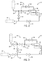
- FIG. 3 is a schematic diagram of an embodiment of the throttle valve 50 of the turbine system 12 of FIG. 2 , where the throttle valve 50 is disposed in different positions within the turbine system 12.
- the throttle valve 50 may be disposed along the exit flow path 62 downstream of the turbine 42 and upstream of a first joining point 64 between the bypass flow path 60 and outlet 59.
- a throttle valve 66 may be disposed along the exit flow path 62 downstream of the turbine 42 and the joining point 64.
- a throttle valve 68 may be disposed downstream of the high pressure reaction vessel 18 and upstream of a second joining point 70 between the main flow path 52 and the bypass flow path 60.
- a throttle valve 72 may be disposed downstream of the second joining point 70, upstream of the turbine 42, and upstream of a third joining point 73 before the main flow path 52 and the auxiliary flow path 56. In other embodiments, the throttle valve 72 may be disposed downstream of the second joining point 70, upstream of the turbine 42, and downstream of the third joining point 73.
- the throttle valves 50 or 66 may be configured to increase the resistance within the turbine system 12 by restricting the flow exiting from the turbine 42, thereby providing the turbine system 12 with a mechanism to handle low flow profiles.
- the throttle valves 68 and 72 may be configured to increase resistance and limit the flow of the high pressure rich solvent 28 from the high pressure reaction vessel 18.
- the throttle valves 50, 66, 68, and 72 may be utilized in any combination, to regulate and route the flow of the high pressure rich solvent 28 in the manner desired.
- the throttle valve 72 may be closed to limit the flow of the high pressure rich solvent 28 to the turbine 42 and may direct the high pressure rich solvent 28 to the exit flow path 62.
- valves 44 may be disposed upstream or downstream of the turbine 42, in order to help provide the turbine system 12 handle a broader range of flow profiles. Further still, additional mechanisms may be provided to the turbine system 12 with a further nuanced control of the high pressure rich solvent 28 flow, as further described with respect to FIG. 4 .
- FIG. 4 is a schematic diagram of an embodiment of the turbine system of FIG. 2 , where one or more valves of the turbine system 12 are coupled to a monitoring/analysis system 74.
- the monitoring/analysis system 74 may include a controller 76 coupled to a display 78, one or more processors 80, and a memory 82.
- the controller 76 may be configured to communicate with and collect information from one or more components of the turbine system 12, such as the one or more valves 44 or one or more sensors 75.
- the controller 76 may be configured to regulate and control one or more operating parameters of the turbine system 12.
- the processor 80 may include one or more processing devices, and the memory 82 may include one or more tangible, non-transitory, machine-readable media collectively storing instructions executable by the processor 80 to perform the methods and control actions described herein.
- Such machine-readable media can be any available media that can be accessed by the processor or by any general purpose or special purpose computer or other machine with a processor.
- machine-readable media can include RAM, ROM, EPROM, EEPROM, CD-ROM, or other optical disk storage, magnetic disk storage or other magnetic storage devices, or any other medium which can be used to carry or store desired program code in the form of machine-executable instructions or data structures and which can be accessed by the processor or by any general purpose or special purpose computer or other machine with a processor.
- a network or another communications connection either hardwired, wireless, or a combination of hardwired or wireless
- Machine-executable instructions comprise, for example, instructions and data which cause the processor or any general purpose computer, special purpose computer, or special purpose processing machines to perform a certain function or group of functions.
- the controller 76 may be configured to communicate with electric actuators, switches (e.g., Hall switches, solenoid switches, relay switches, limit switches), and so forth, that may be coupled to each of the one or more valves 44. In this manner, the controller 76 may be configured to open, close, partially open, or partially close any of the valves 44, based on the desired flow profiles throughout the acid gas removal system 10. Further, in certain embodiments, the controller 76 may be configured to communicate with a variety of sensing devices 75 disposed throughout the turbine system 12 and the acid gas removal system 10. The sensing devices 75 may include, flow meters, temperature sensors, vibration sensors, clearance sensors, pressure sensors, or other sensors configured to sense an operating parameter of the acid gas removal system 10.
- the sensing devices 75 may be configured to sense temperature, pressure, flow rate, reaction rates, and so forth, of the high pressure rich solvent 28, the low pressure rich solvent 30, the lean solvent solution 20, the feed gas 16, and so forth.
- the sensing devices 75 may be disposed within the turbine system 12, such as along the flow paths 52, 56, 60, or 62 of the turbine system 12.
- the high pressure reaction vessel 18 may include a level transmitter 84 configured to monitor various operating parameters of the high pressure reaction vessel 18.
- the level transmitter 84 may be configured to provide information related to the exothermic process within the contractor 18 between the lean solvent solution 20 and the feed gas 16.
- the information gathered by the level transmitter and transmitted to the controller 76 may include information related to the temperature, pressure, reaction rate, amount of sweet gas 26 generated, amount of high pressure rich solvent 28 generated, and so forth.
- the level transmitter 84 and various other sensing devices 75 that may be disposed within the high pressure reaction vessel 18 may be utilized to determine the amount of high pressure rich solvent 28 that is routed out of the high pressure reaction vessel 18.
- the controller 76 may be configured to regulate the valves 44 in order to achieve the desired flow profiles. For example, if the controller 76 receives information that the amount of the high pressure rich solvent routed out of the high pressure reaction vessel 18 is greater than the flow capacity or the flow limit that the main nozzle 54 can handle, the controller 76 may be configured to open or partially open the auxiliary nozzle valve 46. Likewise, if the controller 76 receives information or feedback that the amount of the high pressure rich solvent routed out of the high pressure reaction vessel 18 is less than the flow capacity or flow limit that the main nozzle 54 can handle, the controller 76 may be configured to close or partially close the auxiliary nozzle valve 46.
- the controller 76 may be configured to open or partially open the bypass valve 48. Likewise, if the controller 76 receives information or feedback that the amount of the high pressure rich solvent routed out of the high pressure reaction vessel 18 is less than approximately 10%-20% of the flow capacity that the auxiliary nozzle 58 can handle, the controller 76 may be configured to close or partially close one or more throttle valves 50, 66, 68, 72.
- sensing information may also be utilized (e.g., level transmitter 84 information) to control the valves 44 in a manner that improves the overall efficiency of the turbine system 12.
- level transmitter 84 information e.g., level transmitter 84 information
- the bypass valve 48 may be closed, the auxiliary nozzle valve 46 may be closed, and the throttle valve 50 may be either fully or partially closed.
- various valves 44 may be configured to open to accommodate the additional flow.
- the throttle valve 50 may be configured to open to the enable the turbine 42 to output a stream of low pressure rich solvent 30.
- the auxiliary vale 46 and/or the bypass valve 48 may also be configured to open.
- valves 44 may be operated in any combination, and the valves 44 may have overlapping ranges of operation.
- the auxiliary nozzle valve 46 may be configured to open before the throttle valve 50 is completely open, at the same time that the throttle valve 50 is configured to open, or after the throttle valve 50 is configured to open.
- the bypass valve 48 may be configured to open before the auxiliary nozzle valve 46 is configured to open, at the same time that the auxiliary nozzle valve 46 is configured to open, or after the auxiliary nozzle valve 46 is configured to open.
- the monitoring/analysis system 74 may allow for operator interaction with the acid gas removal system 10.
- the display 78 of the monitoring/analysis system 74 includes a human-machine interface (e.g., HMI), which may be utilized by an operator to receive sensing information or manual instructions.
- HMI human-machine interface
- the HMI may include user inputs/outputs configured to receive or provide information from an operator.
- an operator may be configured to enter operational ranges for each of the valves 44.
- the display 78 may be utilized to display information received from the sensing devices 75 or information generally related to any component of the turbine system 12 or the acid gas removal system 10.
- FIG. 5 is a perspective view of an embodiment of the turbine 42 (e.g., liquid turbine) disposed within the turbine system 12 of FIG. 2 .
- the turbine 42 includes the main nozzle 54 configured to directly receive the high pressure rich solvent 28 via the main flow path 52.
- the turbine 42 includes the auxiliary nozzle 58 configured to receive the high pressure rich solvent 28 via the auxiliary flow path 56, and which is regulated by the auxiliary nozzle valve 46.
Landscapes
- Chemical & Material Sciences (AREA)
- Engineering & Computer Science (AREA)
- Oil, Petroleum & Natural Gas (AREA)
- Chemical Kinetics & Catalysis (AREA)
- General Chemical & Material Sciences (AREA)
- Analytical Chemistry (AREA)
- Combustion & Propulsion (AREA)
- Mechanical Engineering (AREA)
- General Engineering & Computer Science (AREA)
- Organic Chemistry (AREA)
- Gas Separation By Absorption (AREA)
- Physical Or Chemical Processes And Apparatus (AREA)
Description
- This section is intended to introduce the reader to various aspects of art that may be related to various aspects of the present invention, which are described and/or claimed below. This discussion is believed to be helpful in providing the reader with background information to facilitate a better understanding of the various aspects of the present invention. Accordingly, it should be understood that these statements are to be read in this light, and not as admissions of prior art.
- The subject matter discloses herein relates to turbine systems, and more particularly, to systems and methods for controlling operating parameters of a fluid within gas processing systems, such as within acid gas removal systems.
- Within various industrial applications, high pressure reaction vessels may be utilized for various gas processing applications. For example, within various petrochemical applications, natural gas processing applications, and other industrial processing plant applications, acid gas removal systems may utilize a high pressure reaction vessel (e.g., high pressure reaction vessel) to remove sour gas components of a desired gas. Indeed, a natural gas emerging from a natural reservoir may contain varying amounts of sour gases (e.g., carbon dioxide, hydrogen sulfide, etc.). It may be beneficial for the high pressure reaction vessels to remove the sour gas components of the natural gas to help reduce the effects of the sour gases on or within these industrial applications.
- In some situations, a liquid solvent may exit the high pressure reaction vessel and may be processed before being routed back into the high pressure reaction vessel as a reactant. For example, the liquid solvent may be passed through a pressure reduction mechanism which modulates in order to control a liquid level within the high pressure reaction vessel. Within acid gas removal systems, various operating parameters of a liquid solvent exiting the high pressure reaction vessel may be adjusted to help provide for a continuous system that removes sour gas components from the feed gas. In certain situations, the pressures and temperatures of the liquid solvent are increased or decreased before or after the sour gas components are stripped from the feed gas. However, mechanisms generally utilized to control the operating parameters of the liquid solvent, such as the pressure reduction mechanism, may be improved to increase efficiency and recover lost energy. Accordingly, it may be beneficial to provide systems and methods for improving mechanisms utilized to control the operating parameters of liquid solvents exiting high pressure reaction vessels within various industrial processes.
- The document
US 2013/0019530 A1 describes a method and apparatus for sweetening and dehydrating a hydrocarbon gas. A sweetening chamber and a dehydration chamber are arranged within a vertical elongated container. Exhausted sweetening liquid and exhausted dehydration liquid are expanded in respective turbines. - The document
FR 2137359 A - The document
US 3,602,603 A describes an apparatus for operating a water turbine which comprises an auxiliary needle valve and a main needle valve. During starting-up, only the auxiliary needle valve is operated to finely control the rotational speed of the turbine until it reaches synchronization speed. - The invention is defined in the independent claims. The dependent claims describe embodiments of the invention.
- According to an embodiment of the invention, there is provided a system, comprising: a solvent gas processing system, comprising: a high pressure reaction vessel configured to remove an acid gas from an untreated feed gas using a liquid solvent in a lean solvent fluid stream, wherein the high pressure reaction vessel is configured to output a treated clean gas and a first flow of a high pressure fluid stream comprising the liquid solvent having absorbed acid gas from the untreated feed gas via a first flow path; a turbine having a main nozzle, an auxiliary nozzle, and an outlet, wherein the main nozzle is configured to receive a second flow of the high pressure fluid stream from the first flow path via a main flow path, and wherein the second flow of the high pressure fluid stream is configured to drive the turbine. The turbine further has an auxiliary nozzle. The second flow of the high pressure fluid stream is a portion of the first flow, and the high pressure fluid stream is configured to drive the turbine. The solvent gas processing system further comprises an auxiliary nozzle valve disposed along an auxiliary flow path, wherein the auxiliary nozzle valve is configured to control a third flow of the high pressure fluid stream into the auxiliary nozzle of the turbine, and wherein the third flow of the high pressure fluid stream is a portion of the first flow.
- In particular, the turbine is configured to receive a first pressure of the high pressure fluid stream and output a second pressure of the low pressure fluid stream, and the turbine is configured to generate rotational mechanical energy based on the difference between the first pressure and the second pressure.
- Various features, aspects, and advantages of the present invention will become better understood when the following detailed description is read with reference to the accompanying figures in which like characters represent like parts throughout the figures, wherein:
-
FIG. 1 is a schematic diagram of an embodiment of an acid gas removal system, depicting a turbine system configured to received a high pressure fluid from a high pressure reaction vessel; -
FIG. 2 is a schematic diagram of an embodiment of the turbine system ofFIG. 1 , where the turbine system includes an auxiliary nozzle valve, a bypass valve, and a throttle valve; -
FIG. 3 is a schematic diagram of an embodiment of the throttle valve of the turbine system ofFIG. 2 , where the throttle valve is disposed in different positions within the turbine system; -
FIG. 4 is a schematic diagram of an embodiment of the turbine system ofFIG. 2 , where one or more valves of the turbine system are coupled to a monitoring/analysis system; and -
FIG. 5 is a perspective view of an embodiment of a turbine disposed within the turbine system ofFIG. 2 . - One or more specific embodiments of the present invention will be described below. These described embodiments are only exemplary of the present invention. Additionally, in an effort to provide a concise description of these exemplary embodiments, all features of an actual implementation may not be described in the specification. It should be appreciated that in the development of any such actual implementation, as in any engineering or design project, numerous implementation-specific decisions must be made to achieve the developers' specific goals, such as compliance with system-related and business-related constraints, which may vary from one implementation to another. Moreover, it should be appreciated that such a development effort might be complex and time consuming, but would nevertheless be a routine undertaking of design, fabrication, and manufacture for those of ordinary skill having the benefit of this disclosure.
- When introducing elements of various embodiments of the present invention, the articles "a," "an," "the," and "said" are intended to mean that there are one or more of the elements. The terms "comprising," "including," and "having" are intended to be inclusive and mean that there may be additional elements other than the listed elements
- The embodiments described herein generally relate to industrial applications that utilize high pressure reaction vessels in various gas processing techniques. For example, within various petrochemical applications, natural gas processing applications, and other industrial processing plant applications, high pressure reaction vessels may be utilized to process a desired gas with a liquid solvent. In particular, the liquid level of the high pressure reaction vessels within these industrial systems may be regulated and monitored. For example, in certain embodiments, a liquid solvent may be removed from the high pressure reaction vessel and passed through a pressure reduction valve before being routed back into the high pressure reaction vessel as a reactant. Further, the pressure reduction valve may be configured to regulate the liquid level of the high pressure reaction vessel by monitoring and regulating the amount of liquid solvent removed from the high pressure reaction vessel. However, the mechanisms generally utilized to control the operating parameters of the liquid solvent, such as the pressure reduction mechanism, may be improved to increase efficiency and recover lost energy. Accordingly, it may be beneficial to provide for a turbine system that is configured to control or regulate the operating parameters of the liquid solvent exiting from a high pressure reaction vessel, as further described below.
- It should be noted that in the illustrated examples, descriptions, and embodiments, an acid gas removal system is utilized as an example of an industrial system having a turbine system configured to regulate the operating parameters of the liquid solvent exiting from a high pressure reaction vessel. However, the embodiments, systems, and methods described herein are generally applicable to any industrial process through which a liquid solvent is routed out of a high pressure reaction vessel. Further, these embodiments, systems, and methods described herein are generally applicable to any industrial process in which a liquid solvent is routed out of a high pressure reaction vessel and is passed through a pressure reduction valve configured to control the liquid level in the high pressure reaction vessel.
- With the forgoing in mind, acid gas removal systems may be an example of an industrial process having a turbine system configured to regulate the operating parameters of a liquid solvent (e.g., liquid stream, liquid effluent, etc.) exiting from a high pressure reaction vessel. Further, the turbine system may be configured to regulate the operating parameters of the high pressure reaction vessel by controlling or regulating the amount of liquid solvent removed from the high pressure reaction vessel for further processing. Acid gas removal systems may be utilized in a variety of industrial applications, such as petrochemical or chemical applications, natural gas processing applications, industrial plant applications, and so forth. In particular, the acid gas removal systems may include a turbine system having a turbine and one or more valves that are configured to control a flow of a liquid solvent within the acid gas removal system. Furthermore, the turbine system may help regulate the pressure and the pressure drop of the liquid solvent stream as it is processed through the acid gas removal system. In this manner, the turbine system may be configured to replace other mechanisms within the acid gas removal systems typically utilized for pressure reduction of the desired liquid, such as, for example, a pressure reducing valve.
- Acid gas removal systems may generally be utilized to remove sour gas components of a desired feed gas, thereby converting the feed gas into a clean gas (e.g., sweet gas) substantially free of sour gas components. For example, virgin natural gas is a type of desired feed gas derived from natural gas reservoirs that may include various amounts of sour gases, such as carbon dioxide or hydrogen sulfide. The acid gas removal system may be configured to remove the sour gas components of the natural gas to help reduce the effects of the sour gases on the industrial system or process. Typically, acid gas removal systems utilize a series of processes involving aqueous solutions of various fluid solvents (e.g., alkylamines, amines) to remove the sour gas components. Specifically, sour gas components of a desired feed gas are absorbed by the solvent aqueous solutions at high pressures (e.g., approximately between 6.89 MPa (1000 psi) and 10.34 MPa (1500 psi)) and relatively low temperatures (e.g.,). Likewise, the sour gas components are released by the solvent aqueous solutions at low pressures (e.g. approximately near atmospheric pressures) and relatively higher temperatures (e.g.,). Accordingly, acid gas removal systems typically include a circulative process that reuses the aqueous solvent solutions. For example, the sour gas components of a desired feed gas, such as natural gas, are brought into contact with a solvent solution at high pressures (e.g., approximately between 6.89 MPa (1000 psi) and 10.34 MPa (1500 psi)) and relatively low temperatures (e.g.,) within a high pressure reaction vessel, which results in the solvent solution absorbing the sour gas components and forming a clean (e.g., sweet) feed gas. The sweet gas is produced by the acid gas removal system. Further, the solvent solution that has absorbed the sour gas components (e.g., high pressure rich solvent fluid stream) may exit the high pressure reaction vessel at high pressures and low temperatures. Lowering the pressure and increasing the temperature of the high pressure rich solvent fluid may help strip the high pressure rich solvent of the absorbed sour gas components, thereby allowing the solvent fluid stream to be recirculated into the high pressure reaction vessel. Typically, in certain acid gas removal systems and situations, a pressure reducing valve may be utilized to reduce the pressure of the high pressure rich solvent fluid. However, the pressure reducing valve may not utilize the energy generated with the pressure drop of the rich solvent fluid, thereby resulting in a loss of efficiency.
- As noted above, in embodiments described herein, the turbine system may be configured to help reduce the pressure of the high pressure rich solvent fluid. Indeed, as further described in detail below, in certain situations the turbine system may be disposed to help replace the pressure reducing valve within various acid gas removal systems. In particular, the turbine system may be configured to recover a portion of the pressure energy generated when the pressure of the rich solvent solution is reduced, and may convert this pressure energy into rotational mechanical energy. In certain embodiments, the rotational mechanical energy may be utilized and/or converted into other forms of energy within the acid gas removal system and/or the industrial system. For example, the rotational energy generated by the turbine system may be utilized to drive a pump to pressurize additional process fluids within the system, to convert to electrical energy through driving an electric generator, or may be used in any other manner within the acid gas removal system.
- With the forgoing in mind,
FIG. 1 is a schematic diagram of an embodiment of an acidgas removal system 10 with aturbine system 12. Theturbine system 12 includes a turbine (e.g., hydraulic turbine, liquid turbine, etc.) and one or more valves, as further described with respect toFIGS. 2-5 . In particular, as noted above, the turbine system may be configured to replace apressure reducing valve 14 disposed within typical acid gas removal systems, as further described in detail below. Further, while the system and methods described herein are generally described with regard to a specific type of acid gas removal system (e.g., natural gas processing using an aqueous solvent solution), it should be noted that the techniques and mechanisms described might be utilized with any acidgas removal system 10. For example, the embodiments described herein may be utilized with any acidgas removal system 10 having apressure reducing valve 14 that may be replaced with theturbine system 12. Indeed, as noted above, utilizing theturbine system 12 in the place of thepressure reducing valve 14 may help increase efficiency of thesystem 10, and may help recover a portion of the pressure energy generated and convert the generated pressure energy into rotational mechanical energy. - In certain embodiments, the acid
gas removal system 10 includes a desiredfeed gas 16 that is provided to abase 17 of a highpressure reaction vessel 18. Thefeed gas 16 may be any type of gas that includes sour gas components (e.g., acid gases). For example, types offeed gas 16 may include natural gas (e.g., ethane, propane, etc.) derived from natural geological reservoirs, syngas, or generally any type of gas with acid gas components. Sour gas components of thefeed gas 16 may include carbon dioxide, hydrogen sulfide, mercaptans (e.g., methanethiol, ethanetiol, etc.), and so forth. In certain embodiments, thefeed gas 16 may enter the highpressure reaction vessel 18 at pressures between approximately 2.06 MPa (gauge) (300 psig) and 15.17 MPa (gauge) (2200 psig). In addition, the temperature of thefeed gas 16 as it enters the highpressure reaction vessel 18 may be approximately between 26 degrees and 38 degrees Celsius. Furthermore, the acidgas removal system 10 includes a lean solvent solution 20 (e.g., lean solvent aqueous solution, lean solvent solution, water based lean solvent solution, etc.) that is provided generally near a top 19 of the highpressure reaction vessel 18 at generally low temperatures. In certain embodiments, the temperature of the leansolvent solution 20 as it enters the highpressure reaction vessel 18 may be between approximately 32 degrees and 43 degrees Celsius or between approximately 38 degrees or 49 degrees Celsius. Indeed, in certain embodiments, the temperature of the leansolvent solution 20 may be anywhere between 30 degrees and 50 degrees Celsius, at temperatures higher than thefeed gas temperatures 16, in order to help avoid condensation of the heavier components of thefeed gas 16. As thefeed gas 16 moves in anupward direction 22 within the highpressure reaction vessel 18, thefeed gas 16 makes contact with the leansolvent solution 20 in an exothermic process. - Accordingly, in certain embodiments, the lean
solvent solution 20 heats up in the exothermic process, and the sour gas components of thefeed gas 16 may be transferred from thefeed gas 16 to the leansolvent solution 20 as the lean solvent solution moves in thedownward direction 24 within the highpressure reaction vessel 18. In this manner, sweet gas 26 (e.g., clean gas 26) exits the high pressure reaction vessel. Specifically, thesweet gas 26 may be the desiredfeed gas 16 void of the sour gas components. Further, the leansolvent solution 20 absorbs the sour gas components, and exits the highpressure reaction vessel 18 at high pressures (e.g., approximately between 6.89 MPa (1000 psi) and 10.34 MPa (1500 psi)) and generally high temperatures (e.g., between approximately 55 degrees and 65 degrees Celsius) as a high pressure rich solvent 28. As noted above, it may be beneficial to recycle and recirculate the solvent solution within the acidgas removal system 10. Accordingly, in certain embodiments, the high pressure rich solvent 28 is further processed to strip the sour gas components to generate the leansolvent solution 20. Therefore, in certain embodiments, the pressure of the high pressure rich solvent 28 may be reduced to strip the sour gas components. Also in certain embodiments, the temperature of the high pressure rich solvent 28 may be increased to strip the sour gas components. - The
turbine system 12 may be configured to reduce the pressure of the high pressure rich solvent 28, as further described with respect toFIGS. 2-4 . For example, in certain embodiments, the pressure of the high pressure rich solvent 28 may be reduced to between approximately 172 kPa (gauge) (25 psig) and 689 kPa (gauge) (100 psig). Accordingly, the low pressure rich solvent 30 exiting from theturbine system 12 may be routed to aflash tank 32. Theflash tank 32 may be configured to flash and recover desired components of the low pressure rich solvent 30, such as any remaining hydrocarbon gases. Further, the low pressure rich solvent 30 may be then routed to aheat exchanger 34, and to furtherdownstream processing 36. Thedownstream processing 36 is configured to strip the low pressure rich solvent 30 of the sour gas components. In certain embodiments, thedownstream processing 36 may include a regenerator circuit, where the sour gas components are stripped from the low pressure rich solvent 30 with the application of heat to generate the leansolvent solution 20. In certain embodiments, theheat exchanger 34 is configured to exchange heat between the low pressure rich solvent 30 enteringheat exchanger 34 and the leansolvent solution 20 that exits thedownstream processing unit 36. Further, the leansolvent solution 20 exiting theheat exchanger 34 enters a leansolvent pump 38 that is configured to increase the pressure of the leansolvent solution 20 to the pressure of the high pressure reaction vessel 18 (e.g., from between approximately 172 kPa (gauge) (25 psig) and 689 kPa (gauge) (100 psig) to between approximately 6.89 MPa (gauge) (1000 psig) and 8.27 MPa (gauge) (1200 psig)). The leansolvent solution 20 is then routed back to the highpressure reaction vessel 18 when a leansolvent valve 40 is configured to open. In certain embodiments, the energy needed to increase the pressure of the leansolvent solution 20 may be derived from the energy generated by theturbine system 12. -
FIG. 2 is a schematic diagram of an embodiment of theturbine system 12 ofFIG. 1 , where theturbine system 12 includes aturbine 42 and one ormore valves 44. In the illustrated embodiment, thevalves 44 includeauxiliary nozzle valve 46, abypass valve 48, and athrottle valve 50. In particular, thevalves 44 may be configured to regulate the flow of the high pressure rich solvent 28 exiting from the highpressure reaction vessel 18 and routed into theturbine 42. It should noted that control of the solvent recirculation process within the acidgas removal system 10 may be regulated by controlling the flow of the leansolvent solution 20 and the flow of the high pressure rich solvent 28 exiting the highpressure reaction vessel 18. In this manner, theturbine system 12 may be configured to help control the overall process of the acidgas removal system 10 by regulating and providing resistance to the flow exiting the highpressure reaction vessel 18. Indeed, thevalves 44 may work concurrently to simultaneously control and/or regulate the flow of the high pressure rich solvent 28 exiting the highpressure reaction vessel 18 and the flow of the high pressure rich solvent 28 entering theturbine 42. - In certain embodiments, the high pressure rich solvent 28 may be routed directly from the high
pressure reaction vessel 18 and into theturbine 42 via amain flow path 52 leading to a main nozzle 54 (e.g., primary nozzles 54) of theturbine 42. Indeed, themain nozzle 54 may be continuously open to the stream of the high pressure rich solvent 28 exiting from the highpressure reaction vessel 18 without any elements configured to restrict or control the flow. In certain embodiments, it may be necessary to increase the amount of flow exiting the highpressure reaction vessel 18 and entering theturbine 42. In these situations, theauxiliary nozzle valve 46 may be opened or engaged to increase the amount of flow into theturbine 42. For example, in certain situations, anauxiliary flow path 56 may branch off from themain flow path 52 and route a portion of the high pressure rich solvent into anauxiliary nozzle 58 via theauxiliary nozzle valve 46. When theauxiliary nozzle valve 46 is fully opened, theturbine 42 may be configured to receive the maximum amount of high pressure rich solvent 28 exiting from the highpressure reaction vessel 18. It should be noted that in some embodiments, theauxiliary nozzle valve 46 may be partially opened, so an amount of high pressure rich solvent 28 is removed from the highpressure reaction vessel 18 and is routed to theturbine 42. As noted above, the amount of high pressure rich solvent 28 routed into theturbine 42 may be dependent on the desired operating parameters of the overall recirculative process of the acidgas removal system 10. For example, when the liquid level in the high pressure reaction vessel increases beyond the acceptable limits, a greater amount of high pressure rich solvent 28 may be required to be removed from the highpressure reaction vessel 18 in order to control the liquid level in the highpressure reaction vessel 18. - In certain embodiments, the
turbine system 12 may be configured to handle a broader range of flow capacities. For example, in some situations, theturbine system 12 may be configured to handle additional flow exiting from the highpressure reaction vessel 18, such as flow surpassing the maximum flow that themain flow path 52 andauxiliary flow path 56 can handle. In these situations, thebypass valve 48 may be fully or partially opened to handle the overflow of the high pressure rich solvent 28 exiting from the highpressure reaction vessel 18. In particular, abypass flow path 60 may branch from themain flow path 52 to route a portion of the high pressure rich solvent 28 directly from the highpressure reaction vessel 18 to a flow path downstream of theturbine 42. The highpressure reaction vessel 18 may include anoutlet 21 through which the high pressure rich solvent 28 exits the highpressure reaction vessel 18. In certain embodiments, thebypass flow path 60 may route the high pressure rich solvent 28 to an exit flow path downstream of theturbine 42 and thethrottle valve 50. In certain embodiments, thethrottle valve 50 may also be utilized to improve the range of flows theturbine system 12 can manage. For example, in some situations, theturbine system 12 may be configured to handle a smaller amount of flow, such as flow falling below the minimum flow that themain flow path 52 is configured to handle. In these situations, thethrottle valve 50 may be fully or partially closed to handle the decrease flow of the high pressure rich solvent 28 exiting from the highpressure reaction vessel 18. For example, closing thethrottle valve 50 may help provide additional resistance within theturbine system 12. As noted above, theturbine 42 is generally configured to reduce the pressure of the high pressure rich solvent 28, and output the low pressure rich solvent 30 through theturbine outlet 59 and to theexit flow path 62. - In certain embodiments, a plurality of
auxiliary nozzle valves 46,auxiliary flow paths 56, andauxiliary nozzles 58 may be provided and configured with theturbine 42. For example, one or more auxiliary nozzle valves 46 (e.g., 2, 3, 4, 5, 6, or more) and correspondingauxiliary flow paths 56 andauxiliary nozzles 58 may be configured with theturbine 42. Furthermore, it should be noted that in some situations, a plurality of turbine systems 12 (e.g., 2, 3, 4, 5, 6, or more) may be provided within the acidgas removal system 10. In these situations, themain flow path 52 exiting the highpressure reaction vessel 18 may be split into a plurality ofmain flow paths 52. Each one of the plurality ofmain flow paths 52 may lead to aparticular turbine system 12 of the plurality ofturbine system 12. -
FIG. 3 is a schematic diagram of an embodiment of thethrottle valve 50 of theturbine system 12 ofFIG. 2 , where thethrottle valve 50 is disposed in different positions within theturbine system 12. For example, as noted above with respect toFIG. 2 , thethrottle valve 50 may be disposed along theexit flow path 62 downstream of theturbine 42 and upstream of a first joiningpoint 64 between thebypass flow path 60 andoutlet 59. In other embodiments, athrottle valve 66 may be disposed along theexit flow path 62 downstream of theturbine 42 and the joiningpoint 64. In certain embodiments, athrottle valve 68 may be disposed downstream of the highpressure reaction vessel 18 and upstream of a second joiningpoint 70 between themain flow path 52 and thebypass flow path 60. Further, in certain embodiments, athrottle valve 72 may be disposed downstream of the second joiningpoint 70, upstream of theturbine 42, and upstream of a third joiningpoint 73 before themain flow path 52 and theauxiliary flow path 56. In other embodiments, thethrottle valve 72 may be disposed downstream of the second joiningpoint 70, upstream of theturbine 42, and downstream of the third joiningpoint 73. - In certain embodiments, the
throttle valves turbine system 12 by restricting the flow exiting from theturbine 42, thereby providing theturbine system 12 with a mechanism to handle low flow profiles. Thethrottle valves pressure reaction vessel 18. Further, it should be noted that thethrottle valves throttle valve 72 may be closed to limit the flow of the high pressure rich solvent 28 to theturbine 42 and may direct the high pressure rich solvent 28 to theexit flow path 62. It should be noted that in other embodiments, any number ofvalves 44 may be disposed upstream or downstream of theturbine 42, in order to help provide theturbine system 12 handle a broader range of flow profiles. Further still, additional mechanisms may be provided to theturbine system 12 with a further nuanced control of the high pressure rich solvent 28 flow, as further described with respect toFIG. 4 . -
FIG. 4 is a schematic diagram of an embodiment of the turbine system ofFIG. 2 , where one or more valves of theturbine system 12 are coupled to a monitoring/analysis system 74. The monitoring/analysis system 74 may include acontroller 76 coupled to adisplay 78, one ormore processors 80, and amemory 82. Thecontroller 76 may be configured to communicate with and collect information from one or more components of theturbine system 12, such as the one ormore valves 44 or one ormore sensors 75. For example, in certain embodiments, thecontroller 76 may be configured to regulate and control one or more operating parameters of theturbine system 12. - In certain embodiments, the
processor 80 may include one or more processing devices, and thememory 82 may include one or more tangible, non-transitory, machine-readable media collectively storing instructions executable by theprocessor 80 to perform the methods and control actions described herein. - Such machine-readable media can be any available media that can be accessed by the processor or by any general purpose or special purpose computer or other machine with a processor. By way of example, such machine-readable media can include RAM, ROM, EPROM, EEPROM, CD-ROM, or other optical disk storage, magnetic disk storage or other magnetic storage devices, or any other medium which can be used to carry or store desired program code in the form of machine-executable instructions or data structures and which can be accessed by the processor or by any general purpose or special purpose computer or other machine with a processor. When information is transferred or provided over a network or another communications connection (either hardwired, wireless, or a combination of hardwired or wireless) to a machine, the machine properly views the connection as a machine-readable medium. Thus, any such connection is properly termed a machine-readable medium. Combinations of the above are also included within the scope of machine-readable media. Machine-executable instructions comprise, for example, instructions and data which cause the processor or any general purpose computer, special purpose computer, or special purpose processing machines to perform a certain function or group of functions.
- For example, in certain embodiments, the
controller 76 may be configured to communicate with electric actuators, switches (e.g., Hall switches, solenoid switches, relay switches, limit switches), and so forth, that may be coupled to each of the one ormore valves 44. In this manner, thecontroller 76 may be configured to open, close, partially open, or partially close any of thevalves 44, based on the desired flow profiles throughout the acidgas removal system 10. Further, in certain embodiments, thecontroller 76 may be configured to communicate with a variety ofsensing devices 75 disposed throughout theturbine system 12 and the acidgas removal system 10. Thesensing devices 75 may include, flow meters, temperature sensors, vibration sensors, clearance sensors, pressure sensors, or other sensors configured to sense an operating parameter of the acidgas removal system 10. For example, thesensing devices 75 may be configured to sense temperature, pressure, flow rate, reaction rates, and so forth, of the high pressure rich solvent 28, the low pressure rich solvent 30, the leansolvent solution 20, thefeed gas 16, and so forth. In some embodiments, thesensing devices 75 may be disposed within theturbine system 12, such as along theflow paths turbine system 12. - In certain embodiments, particular types of
sensing devices 75 may be disposed within other components of the acidgas removal system 10, such as within the highpressure reaction vessel 18. For example, the highpressure reaction vessel 18 may include alevel transmitter 84 configured to monitor various operating parameters of the highpressure reaction vessel 18. In certain situations, thelevel transmitter 84 may be configured to provide information related to the exothermic process within thecontractor 18 between the leansolvent solution 20 and thefeed gas 16. The information gathered by the level transmitter and transmitted to thecontroller 76 may include information related to the temperature, pressure, reaction rate, amount ofsweet gas 26 generated, amount of high pressure rich solvent 28 generated, and so forth. In particular, thelevel transmitter 84 and variousother sensing devices 75 that may be disposed within the highpressure reaction vessel 18 may be utilized to determine the amount of high pressure rich solvent 28 that is routed out of the highpressure reaction vessel 18. - Further, based on the information or feedback received from the
level transmitter 84 and/orother sensing devices 75, thecontroller 76 may be configured to regulate thevalves 44 in order to achieve the desired flow profiles. For example, if thecontroller 76 receives information that the amount of the high pressure rich solvent routed out of the highpressure reaction vessel 18 is greater than the flow capacity or the flow limit that themain nozzle 54 can handle, thecontroller 76 may be configured to open or partially open theauxiliary nozzle valve 46. Likewise, if thecontroller 76 receives information or feedback that the amount of the high pressure rich solvent routed out of the highpressure reaction vessel 18 is less than the flow capacity or flow limit that themain nozzle 54 can handle, thecontroller 76 may be configured to close or partially close theauxiliary nozzle valve 46. Furthermore, if thecontroller 76 receives information that the amount of the high pressure rich solvent routed out of the highpressure reaction vessel 18 is greater than approximately 10%-20% of the flow capacity that theauxiliary nozzle 58 can handle, thecontroller 76 may be configured to open or partially open thebypass valve 48. Likewise, if thecontroller 76 receives information or feedback that the amount of the high pressure rich solvent routed out of the highpressure reaction vessel 18 is less than approximately 10%-20% of the flow capacity that theauxiliary nozzle 58 can handle, thecontroller 76 may be configured to close or partially close one ormore throttle valves level transmitter 84 information) to control thevalves 44 in a manner that improves the overall efficiency of theturbine system 12. It should be noted that the ranges provided related to the flow capacity and limits handled by each of thevalves 44 is for illustrated purposes, and the ranges that each valve operates within may vary depending on the desired overall system efficiency. - For example, in certain situations, such as when the
turbine system 12 receives an amount of high pressure rich solvent 28 that is less than the operating capacity or limit of themain nozzle 54, thebypass valve 48 may be closed, theauxiliary nozzle valve 46 may be closed, and thethrottle valve 50 may be either fully or partially closed. If information or feedback is received by thecontroller 76 related to an increase in output of the highpressure reaction vessel 18,various valves 44 may be configured to open to accommodate the additional flow. For example, with increasing amount of flow, thethrottle valve 50 may be configured to open to the enable theturbine 42 to output a stream of low pressure rich solvent 30. Further, depending on the amount of additional flow, theauxiliary vale 46 and/or thebypass valve 48 may also be configured to open. - Further, it should be noted that the
valves 44 may be operated in any combination, and thevalves 44 may have overlapping ranges of operation. For example, in certain situations, theauxiliary nozzle valve 46 may be configured to open before thethrottle valve 50 is completely open, at the same time that thethrottle valve 50 is configured to open, or after thethrottle valve 50 is configured to open. Likewise, thebypass valve 48 may be configured to open before theauxiliary nozzle valve 46 is configured to open, at the same time that theauxiliary nozzle valve 46 is configured to open, or after theauxiliary nozzle valve 46 is configured to open. - In certain embodiments, the monitoring/
analysis system 74 may allow for operator interaction with the acidgas removal system 10. For example, thedisplay 78 of the monitoring/analysis system 74 includes a human-machine interface (e.g., HMI), which may be utilized by an operator to receive sensing information or manual instructions. In particular, the HMI may include user inputs/outputs configured to receive or provide information from an operator. For example, in certain situations, an operator may be configured to enter operational ranges for each of thevalves 44. Further, thedisplay 78 may be utilized to display information received from thesensing devices 75 or information generally related to any component of theturbine system 12 or the acidgas removal system 10. -
FIG. 5 is a perspective view of an embodiment of the turbine 42 (e.g., liquid turbine) disposed within theturbine system 12 ofFIG. 2 . In particular, theturbine 42 includes themain nozzle 54 configured to directly receive the high pressure rich solvent 28 via themain flow path 52. Further, theturbine 42 includes theauxiliary nozzle 58 configured to receive the high pressure rich solvent 28 via theauxiliary flow path 56, and which is regulated by theauxiliary nozzle valve 46. - While the invention may be susceptible to various modifications and alternative forms, specific embodiments have been shown by way of example in the drawings and have been described in detail herein. However, it should be understood that the invention is not intended to be limited to the particular forms disclosed. Rather, the invention is to cover all modifications, equivalents, and alternatives falling within the scope of the invention as defined by the following appended claims.
Claims (16)
- A system, comprising:a solvent gas processing system (10), comprising:a high pressure reaction vessel (18) configured to remove an acid gas from an untreated feed gas (16) using a liquid solvent in a lean solvent fluid stream (20), wherein the high pressure reaction vessel (18) is configured to output a treated clean gas (26) and a first flow of a high pressure fluid stream (28) comprising the liquid solvent having absorbed acid gas from the untreated feed gas (16) via a first flow path;a turbine (42) having a main nozzle (54) and an outlet (59), wherein the main nozzle (54) is configured to receive a second flow of the high pressure fluid stream from the first flow path via a main flow path (52), and wherein the second flow of the high pressure fluid stream is configured to drive the turbine (42);characterized in thatthe turbine (42) further has an auxiliary nozzle (58), wherein the second flow of the high pressure fluid stream is a portion of the first flow;and that the solvent gas processing system further comprisesan auxiliary nozzle valve (46) disposed along an auxiliary flow path (56), wherein the auxiliary nozzle valve (46) is configured to control a third flow of the high pressure fluid stream into the auxiliary nozzle (58) of the turbine (42), and wherein the third flow of the high pressure fluid stream is a portion of the first flow.
- The system of claim 1, wherein the solvent gas processing system further comprises:
a first throttle valve (50, 66) disposed along an outlet flow path (62), wherein the first throttle valve (50, 66) is configured to control a fourth flow of a low pressure fluid stream (30) out of the outlet (59). - The system of claim 1 or 2, wherein the auxiliary nozzle valve (46) is configured to open or partially open when the first flow or a desired first flow of the high pressure fluid stream (28) is greater than a first flow capacity of the main nozzle (54), wherein preferably, the auxiliary nozzle valve (46) is configured to close or partially close when the first flow or the desired first flow of the high pressure fluid stream (28) is less than the first flow capacity of the main nozzle (54).
- The system of any of claims 1-3, comprising a bypass valve (48) disposed along a bypass flow path (60), wherein the bypass flow path (60) routes a portion of the high pressure fluid stream (28) from the first flow path directly to the outlet flow path (62), wherein preferably, the bypass valve (48) is configured to open or partially open when the third flow or a desired third flow of the high pressure fluid stream (28) is greater than a second flow capacity of the auxiliary nozzle (58).
- The system of claim 2, wherein the first throttle valve (50, 66) is configured to close or partially close when the first flow or a desired first flow of the high pressure fluid stream (28) is less than a first flow capacity of the main nozzle (54), wherein preferably, the first throttle valve (50, 66) is configured to close or partially close when the fourth flow or a desired fourth flow of the low pressure fluid stream (30) from the outlet (59) is less than a third flow capacity of the outlet (59).
- The system of claim 2 or 5, comprising a second throttle valve (68, 72) disposed along the main flow path or the first flow path, wherein the second throttle valve (68, 72) is configured to control the flow of the high pressure fluid stream (28) from the high pressure reaction vessel (18).
- The system of any of claims 1-6, comprising a controller (76) configured to receive feedback related to at least one operating parameter of the system, wherein the controller (76) is configured to adjust an operating parameter of the system to control the first flow of the high pressure stream (28).
- The system of claim 7, wherein the controller (76) is a solvent gas processing controller comprising at least one processor (80), and a memory (82) configured to execute instructions stored on the memory (82), wherein the at least one processor (80) is configured to:receive feedback from one or more sensors (75) disposed throughout an solvent gas processing system (10) related to one or more operating parameters of the solvent gas processing system (10);determine whether the first flow of the high pressure fluid stream (28) from the high pressure reaction vessel (18) and into a turbine system (12) comprising the turbine (42) is within an operational flow range for the main nozzle (54) of the turbine system (12) based on the received feedback;open the auxiliary nozzle valve (46) if the first flow of the high pressure fluid stream exceeds the operational flow range; andclose the auxiliary nozzle valve (46) if the first flow of the high pressure fluid stream falls below the operational flow range.
- The system of claim 8, wherein the one or more sensors comprises a level transmitter (84) disposed within the high pressure reaction vessel (18), and wherein the level transmitter (84) is configured to transmit information related to the first flow of the high pressure fluid stream (28).
- The system of claim 8 or 9, wherein the one or more operating parameters of the system comprises a pressure, a flow rate, a temperature, or a combination thereof.
- The system of any of claims 8-10, wherein the controller (76) is configured to adjust a bypass valve (48) or a throttle valve (50, 66, 68, 72) to increase or decrease the first flow of the high pressure fluid stream into the turbine system (12), wherein preferably, the controller (76) is configured to adjust the throttle valve (50, 66, 68, 72) to increase or decrease a second flow of a low pressure fluid stream exiting the turbine system (12).
- The system of any of claims 8-11, wherein the controller (76) comprises a display (78) having user inputs and outputs configured to receive the operational flow range from an operator.
- A method, comprising:removing an acid gas from an untreated feed gas (16) within a high pressure reaction vessel (18) using a liquid solvent in a lean solvent fluid stream (20), wherein the high pressure reaction vessel (18) is configured to output a treated clean gas (26) and a first flow of a high pressure fluid stream (28) comprising the liquid solvent having absorbed acid gas from the untreated feed gas (16) via a first flow path;receiving the first flow of the high pressure stream from the high pressure reaction vessel (18) via a turbine system (12) including a turbine (42), wherein the turbine (42) has a main nozzle (54) and an outlet (59), wherein the main nozzle (54) is configured to receive a second flow of the high pressure fluid stream from the first flow path via a main flow path (52), wherein the second flow of the high pressure fluid stream is configured to drive the turbine (42);characterized in thatthe turbine (42) further has an auxiliary nozzle (58), wherein the second flow of the high pressure fluid stream is a portion of the first flow; and that an auxiliary nozzle valve (46) is disposed along an auxiliary flow path (56), and that the method further comprisescontrolling a third flow of the high pressure fluid stream into the auxiliary nozzle (58) of the turbine (42) by the auxiliary nozzle valve (46), wherein the third flow of the high pressure fluid stream is a portion of the first flow.
- The method of claim 13, further comprising:determining, via a solvent gas processing controller (76), whether the first flow of the high pressure fluid stream falls within an operational flow range of the main nozzle (54) of the turbine system (12); andadjusting one or more operational parameters of the turbine system (12) if the first flow of the high pressure fluid stream falls outside of the operational flow range of the main nozzle (54).
- The method of claim 14, comprising controlling the auxiliary nozzle valve (46), a bypass valve (48), or a throttle valve (50, 66, 68, 72) to increase or decrease the first flow of the high pressure fluid stream (28) to the turbine system (12) if the first flow of the high pressure fluid stream falls outside of the operational flow range of the main nozzle (54), wherein preferably, the method comprises controlling a bypass valve (46) or a throttle valve (50, 66, 68, 72) to increase or decrease the first flow of the high pressure stream to the turbine system (12) if the first flow of the high pressure fluid stream falls outside of the operational flow range of the main nozzle (54) and a second operational flow range of the auxiliary nozzle (58).
- The method of claim 14 or 15, wherein adjusting the one or more operational parameters comprises controlling the first flow of the high pressure fluid stream (28) through the turbine system (12).
Applications Claiming Priority (3)
| Application Number | Priority Date | Filing Date | Title |
|---|---|---|---|
| US201361896255P | 2013-10-28 | 2013-10-28 | |
| US14/525,081 US9764272B2 (en) | 2013-10-28 | 2014-10-27 | Systems and methods for utilizing turbine systems within gas processing systems |
| PCT/US2014/062535 WO2015065949A1 (en) | 2013-10-28 | 2014-10-28 | Systems and methods for utilizing turbine systems within gas processing systems |
Publications (2)
| Publication Number | Publication Date |
|---|---|
| EP3062913A1 EP3062913A1 (en) | 2016-09-07 |
| EP3062913B1 true EP3062913B1 (en) | 2020-10-28 |
Family
ID=52995711
Family Applications (1)
| Application Number | Title | Priority Date | Filing Date |
|---|---|---|---|
| EP14795926.6A Active EP3062913B1 (en) | 2013-10-28 | 2014-10-28 | Systems and methods for utilizing turbine systems within gas processing systems |
Country Status (10)
| Country | Link |
|---|---|
| US (1) | US9764272B2 (en) |
| EP (1) | EP3062913B1 (en) |
| JP (1) | JP6259110B2 (en) |
| KR (1) | KR101978752B1 (en) |
| CN (1) | CN106470750A (en) |
| CA (1) | CA2929094C (en) |
| MX (1) | MX2016005581A (en) |
| RU (1) | RU2637247C1 (en) |
| SA (1) | SA516371034B1 (en) |
| WO (1) | WO2015065949A1 (en) |
Families Citing this family (32)
| Publication number | Priority date | Publication date | Assignee | Title |
|---|---|---|---|---|
| US10161421B2 (en) | 2015-02-03 | 2018-12-25 | Eli Oklejas, Jr. | Method and system for injecting a process fluid using a high pressure drive fluid |
| CN105401990B (en) * | 2015-11-23 | 2017-05-31 | 北京建筑大学 | A kind of pressure energy of natural gas generating regulator and method |
| EP3318315B1 (en) * | 2016-11-04 | 2020-10-14 | General Electric Technology GmbH | Method and systems for energy recovery for marine exhaust gas control systems |
| US10837465B2 (en) | 2017-02-10 | 2020-11-17 | Vector Technologies Llc | Elongated tank for use in injecting slurry |
| US10766009B2 (en) | 2017-02-10 | 2020-09-08 | Vector Technologies Llc | Slurry injection system and method for operating the same |
| US10156857B2 (en) | 2017-02-10 | 2018-12-18 | Vector Technologies Llc | Method and system for injecting slurry using one slurry pressurizing tank |
| US10156237B2 (en) | 2017-02-10 | 2018-12-18 | Vector Technologies Llc | Method and system for injecting slurry using concentrated slurry pressurization |
| US10156132B2 (en) | 2017-02-10 | 2018-12-18 | Vector Technologies Llc | Method and system for injecting slurry using two tanks with valve timing overlap |
| US10753235B2 (en) | 2018-03-16 | 2020-08-25 | Uop Llc | Use of recovered power in a process |
| US10811884B2 (en) | 2018-03-16 | 2020-10-20 | Uop Llc | Consolidation and use of power recovered from a turbine in a process unit |
| US10829698B2 (en) | 2018-03-16 | 2020-11-10 | Uop Llc | Power recovery from quench and dilution vapor streams |
| US11194301B2 (en) * | 2018-03-16 | 2021-12-07 | Uop Llc | System for power recovery from quench and dilution vapor streams |
| US10690010B2 (en) | 2018-03-16 | 2020-06-23 | Uop Llc | Steam reboiler with turbine |
| US10871085B2 (en) | 2018-03-16 | 2020-12-22 | Uop Llc | Energy-recovery turbines for gas streams |
| US11131218B2 (en) | 2018-03-16 | 2021-09-28 | Uop Llc | Processes for adjusting at least one process condition of a chemical processing unit with a turbine |
| US10508568B2 (en) * | 2018-03-16 | 2019-12-17 | Uop Llc | Process improvement through the addition of power recovery turbine equipment in existing processes |
| US10745631B2 (en) | 2018-03-16 | 2020-08-18 | Uop Llc | Hydroprocessing unit with power recovery turbines |
| US11507031B2 (en) | 2018-03-16 | 2022-11-22 | Uop Llc | Recovered electric power measuring system and method for collecting data from a recovered electric power measuring system |
| US10794225B2 (en) | 2018-03-16 | 2020-10-06 | Uop Llc | Turbine with supersonic separation |
| US10920624B2 (en) | 2018-06-27 | 2021-02-16 | Uop Llc | Energy-recovery turbines for gas streams |
| US10920555B2 (en) | 2018-11-09 | 2021-02-16 | Flowserve Management Company | Fluid exchange devices and related controls, systems, and methods |
| CN112997030B (en) | 2018-11-09 | 2023-10-03 | 芙罗服务管理公司 | Method and valve including flushing feature |
| US12092136B2 (en) | 2018-11-09 | 2024-09-17 | Flowserve Pte. Ltd. | Fluid exchange devices and related controls, systems, and methods |
| CN112996982B (en) | 2018-11-09 | 2023-10-27 | 芙罗服务管理公司 | Fluid exchange devices and related systems and methods |
| CA3119312A1 (en) | 2018-11-09 | 2020-05-14 | Flowserve Management Company | Fluid exchange devices and related controls, systems, and methods |
| WO2020097565A1 (en) | 2018-11-09 | 2020-05-14 | Flowserve Management Company | Pistons for use in fluid exchange devices and related devices, systems, and methods |
| CA3119190A1 (en) | 2018-11-09 | 2020-05-14 | Flowserve Management Company | Fluid exchange devices and related controls, systems, and methods |
| MX2022005109A (en) | 2019-12-12 | 2022-05-30 | Flowserve Man Co | FLUID EXCHANGE DEVICES AND RELATED CONTROLS, SYSTEMS AND METHODS. |
| CN111779614B (en) * | 2020-07-24 | 2025-02-14 | 杨广平 | Gas pressure reduction power generation energy saving device |
| US11629294B2 (en) * | 2021-03-02 | 2023-04-18 | Saudi Arabian Oil Company | Controlling a turbocharger system |
| CN112879203B (en) * | 2021-03-24 | 2022-10-11 | 丁亚南 | External combustion engine power system |
| US12330113B2 (en) * | 2022-04-13 | 2025-06-17 | Saudi Arabian Oil Company | Method and system for maintaining solvent quality in gas treating systems |
Family Cites Families (24)
| Publication number | Priority date | Publication date | Assignee | Title |
|---|---|---|---|---|
| DE1909999A1 (en) | 1968-08-30 | 1970-07-02 | Hitachi Ltd | Control device for a water turbine |
| FR2137359B1 (en) * | 1971-05-14 | 1973-05-25 | Neyrpic | |
| US4150962A (en) | 1975-12-15 | 1979-04-24 | Uop Inc. | Pretreatment of raw natural gas prior to liquefaction |
| JPS60172331A (en) * | 1984-02-20 | 1985-09-05 | Mitsubishi Gas Chem Co Inc | How to recover power |
| JPS60204976A (en) * | 1984-03-29 | 1985-10-16 | Toshiba Corp | Controller for output of pelton waterwheel |
| DE3427134A1 (en) * | 1984-07-24 | 1986-02-06 | Basf Ag, 6700 Ludwigshafen | METHOD FOR REMOVING CO (DOWN ARROW) 2 (DOWN ARROW) AND / OR H (DOWN ARROW) 2 (DOWN ARROW) S FROM GASES |
| DE3443491A1 (en) | 1984-11-29 | 1986-05-28 | Klein, Schanzlin & Becker Ag, 6710 Frankenthal | ENERGY RECOVERY DEVICE |
| IT1190359B (en) * | 1985-05-24 | 1988-02-16 | Snam Progetti | CRYOGENIC PROCEDURE FOR REMOVAL OF ACID GASES FROM GAS MIXTURES BY SOLVENT |
| FR2582876B1 (en) * | 1985-06-04 | 1988-11-18 | Kaeser Charles | PORTABLE HYDROELECTRIC GENERATOR GROUP |
| JPS62143808A (en) * | 1985-12-17 | 1987-06-27 | Nippon Steel Corp | Separation and recovery of carbon monoxide |
| JPH02286881A (en) * | 1989-04-28 | 1990-11-27 | Fuji Electric Co Ltd | Nozzle switching method for pelton hydraulic wheel |
| FR2722110B1 (en) * | 1994-07-08 | 1996-08-30 | Inst Francais Du Petrole | PROCESS FOR DEACIDIFYING A GAS FOR THE PRODUCTION OF CONCENTRATED ACID GASES |
| JP3364103B2 (en) * | 1997-01-27 | 2003-01-08 | 三菱重工業株式会社 | Control method of absorption liquid in decarbonation equipment |
| MXPA04010112A (en) * | 2002-04-15 | 2004-12-13 | Fluor Corp | Configurations and methods for improved acid gas removal. |
| JP4826156B2 (en) * | 2004-07-28 | 2011-11-30 | 三菱マテリアル株式会社 | CO2 gas purification method and apparatus, and CO2 gas absorption liquid used for the purification |
| NO327866B1 (en) * | 2006-03-09 | 2009-10-12 | Abb Research Ltd | A procedure for control and / or monitoring |
| US8808538B2 (en) * | 2008-01-04 | 2014-08-19 | Fluid Equipment Development Company, Llc | Batch-operated reverse osmosis system |
| JP2010201379A (en) * | 2009-03-04 | 2010-09-16 | Toshiba Corp | Carbon dioxide recovery system |
| AU2010230052B2 (en) * | 2009-03-25 | 2013-12-05 | Fluor Technologies Corporation | Improved configurations and methods for high pressure acid gas removal |
| CA2761895C (en) * | 2009-05-26 | 2018-08-28 | Basf Se | Process for recovery of carbon dioxide from a fluid stream, in particular from syngas |
| EA023729B1 (en) | 2009-09-29 | 2016-07-29 | Флуор Текнолоджиз Корпорейшн | Method of feed gas purification from acid components |
| CA2777760C (en) * | 2009-11-02 | 2017-06-27 | Exxonmobil Upstream Research Company | Cryogenic system for removing acid gases from a hydrocarbon gas stream, with removal of hydrogen sulfide |
| ITPI20100038A1 (en) | 2010-03-29 | 2011-09-30 | Sime S R L | METHOD AND APPARATUS FOR THE SOFTENING AND DEHYDRATION OF A GAS BASED ON HYDROCARBONS |
| JP2013039527A (en) * | 2011-08-16 | 2013-02-28 | Babcock Hitachi Kk | Wet-type flue gas desulfurization apparatus, and thermal power generation plant provided with the same |
-
2014
- 2014-10-27 US US14/525,081 patent/US9764272B2/en active Active
- 2014-10-28 KR KR1020167014313A patent/KR101978752B1/en not_active Expired - Fee Related
- 2014-10-28 JP JP2016552201A patent/JP6259110B2/en active Active
- 2014-10-28 CA CA2929094A patent/CA2929094C/en active Active
- 2014-10-28 CN CN201480070987.2A patent/CN106470750A/en active Pending
- 2014-10-28 WO PCT/US2014/062535 patent/WO2015065949A1/en not_active Ceased
- 2014-10-28 RU RU2016120616A patent/RU2637247C1/en active
- 2014-10-28 EP EP14795926.6A patent/EP3062913B1/en active Active
- 2014-10-28 MX MX2016005581A patent/MX2016005581A/en unknown
-
2016
- 2016-04-28 SA SA516371034A patent/SA516371034B1/en unknown
Non-Patent Citations (1)
| Title |
|---|
| None * |
Also Published As
| Publication number | Publication date |
|---|---|
| CA2929094C (en) | 2020-07-21 |
| WO2015065949A1 (en) | 2015-05-07 |
| US20150118131A1 (en) | 2015-04-30 |
| JP6259110B2 (en) | 2018-01-10 |
| KR101978752B1 (en) | 2019-05-15 |
| CN106470750A (en) | 2017-03-01 |
| MX2016005581A (en) | 2017-04-10 |
| US9764272B2 (en) | 2017-09-19 |
| RU2637247C1 (en) | 2017-12-01 |
| CA2929094A1 (en) | 2015-05-07 |
| EP3062913A1 (en) | 2016-09-07 |
| JP2016538130A (en) | 2016-12-08 |
| KR20170020303A (en) | 2017-02-22 |
| SA516371034B1 (en) | 2018-02-15 |
Similar Documents
| Publication | Publication Date | Title |
|---|---|---|
| CA2929094C (en) | Systems and methods for utilizing turbine systems within gas processing systems | |
| EP2916927B1 (en) | Isobaric pressure exchanger controls in amine gas processing | |
| CN103446849A (en) | Separation technology of hydrogen sulfide and carbon dioxide in acid gas of oil refinery | |
| EP3646937A1 (en) | Acidic gas removal apparatus and acidic gas removal method | |
| Nejat et al. | Simulated exergy and energy performance comparison of physical–chemical and chemical solvents in a sour gas treatment plant | |
| WO2016157980A1 (en) | Carbon-dioxide manufacturing facility and carbon-dioxide manufacturing method | |
| JP2025021536A (en) | Adsorption tower control device, gas separation device, method for controlling multiple adsorption towers, and computer program | |
| Naji et al. | Sensitivity analysis of using diethanolamine instead of methyldiethanolamine solution for GASCO’S Habshan acid gases removal plant | |
| Selvan et al. | Mathematical modeling, parametric estimation, and operational control for natural gas sweetening processes | |
| KR102740614B1 (en) | Equipment for wet type carbon dioxide capturing with absorbant recirculation | |
| EP3672712B1 (en) | Method and system for reclaiming amine absorption agent under controlled temperature. | |
| AU2013259640B2 (en) | Systems and methods of inhibiting foam formation using multiphase turbines | |
| Zhang et al. | Sour gas reservoirs and sulfur-removal technologies: A collection of published research (2009–2015) | |
| Mamrosh et al. | Use of Caustic in a Short Contact Time Approach to Selectively Scrub H2S from CO2-Contaminated Gas Streams | |
| JP2016187796A (en) | Carbon dioxide manufacturing facility and carbon dioxide manufacturing method | |
| JP7270124B2 (en) | Carbon dioxide separation and recovery equipment | |
| KR102937982B1 (en) | MEG Recovery Apparatus using Pre-flash Drum | |
| US20210253499A1 (en) | Process and system to purify gas | |
| Li et al. | Multivariable Gain Scheduling Model Predictive Control for Post-Combustion CO 2 Capture System | |
| US9455457B2 (en) | Fuel cell system and method of operating fuel cell system | |
| WO2012154313A1 (en) | System and method for controlling waste heat for co2 capture | |
| JPH09249887A (en) | Absorber regeneration tower controller | |
| Poulad et al. | Dynamic Simulation and Optimization of CO2 Absorption from Ethane Gas in Absorption Tower using ASPEN-HYSYS Process Simulator Software | |
| CN105132059A (en) | Permeating separation desulfurization apparatus and permeating separation desulfurization method |
Legal Events
| Date | Code | Title | Description |
|---|---|---|---|
| PUAI | Public reference made under article 153(3) epc to a published international application that has entered the european phase |
Free format text: ORIGINAL CODE: 0009012 |
|
| 17P | Request for examination filed |
Effective date: 20160525 |
|
| AK | Designated contracting states |
Kind code of ref document: A1 Designated state(s): AL AT BE BG CH CY CZ DE DK EE ES FI FR GB GR HR HU IE IS IT LI LT LU LV MC MK MT NL NO PL PT RO RS SE SI SK SM TR |
|
| AX | Request for extension of the european patent |
Extension state: BA ME |
|
| RAP1 | Party data changed (applicant data changed or rights of an application transferred) |
Owner name: ENERGY RECOVERY, INC. |
|
| DAX | Request for extension of the european patent (deleted) | ||
| STAA | Information on the status of an ep patent application or granted ep patent |
Free format text: STATUS: EXAMINATION IS IN PROGRESS |
|
| 17Q | First examination report despatched |
Effective date: 20190813 |
|
| GRAP | Despatch of communication of intention to grant a patent |
Free format text: ORIGINAL CODE: EPIDOSNIGR1 |
|
| STAA | Information on the status of an ep patent application or granted ep patent |
Free format text: STATUS: GRANT OF PATENT IS INTENDED |
|
| INTG | Intention to grant announced |
Effective date: 20200608 |
|
| GRAS | Grant fee paid |
Free format text: ORIGINAL CODE: EPIDOSNIGR3 |
|
| GRAA | (expected) grant |
Free format text: ORIGINAL CODE: 0009210 |
|
| STAA | Information on the status of an ep patent application or granted ep patent |
Free format text: STATUS: THE PATENT HAS BEEN GRANTED |
|
| AK | Designated contracting states |
Kind code of ref document: B1 Designated state(s): AL AT BE BG CH CY CZ DE DK EE ES FI FR GB GR HR HU IE IS IT LI LT LU LV MC MK MT NL NO PL PT RO RS SE SI SK SM TR |
|
| REG | Reference to a national code |
Ref country code: GB Ref legal event code: FG4D |
|
| REG | Reference to a national code |
Ref country code: CH Ref legal event code: EP |
|
| REG | Reference to a national code |
Ref country code: AT Ref legal event code: REF Ref document number: 1327639 Country of ref document: AT Kind code of ref document: T Effective date: 20201115 |
|
| REG | Reference to a national code |
Ref country code: DE Ref legal event code: R096 Ref document number: 602014071752 Country of ref document: DE |
|
| REG | Reference to a national code |
Ref country code: IE Ref legal event code: FG4D |
|
| REG | Reference to a national code |
Ref country code: AT Ref legal event code: MK05 Ref document number: 1327639 Country of ref document: AT Kind code of ref document: T Effective date: 20201028 |
|
| REG | Reference to a national code |
Ref country code: NL Ref legal event code: MP Effective date: 20201028 |
|
| PG25 | Lapsed in a contracting state [announced via postgrant information from national office to epo] |
Ref country code: GR Free format text: LAPSE BECAUSE OF FAILURE TO SUBMIT A TRANSLATION OF THE DESCRIPTION OR TO PAY THE FEE WITHIN THE PRESCRIBED TIME-LIMIT Effective date: 20210129 Ref country code: RS Free format text: LAPSE BECAUSE OF FAILURE TO SUBMIT A TRANSLATION OF THE DESCRIPTION OR TO PAY THE FEE WITHIN THE PRESCRIBED TIME-LIMIT Effective date: 20201028 Ref country code: FI Free format text: LAPSE BECAUSE OF FAILURE TO SUBMIT A TRANSLATION OF THE DESCRIPTION OR TO PAY THE FEE WITHIN THE PRESCRIBED TIME-LIMIT Effective date: 20201028 Ref country code: NL Free format text: LAPSE BECAUSE OF FAILURE TO SUBMIT A TRANSLATION OF THE DESCRIPTION OR TO PAY THE FEE WITHIN THE PRESCRIBED TIME-LIMIT Effective date: 20201028 Ref country code: PT Free format text: LAPSE BECAUSE OF FAILURE TO SUBMIT A TRANSLATION OF THE DESCRIPTION OR TO PAY THE FEE WITHIN THE PRESCRIBED TIME-LIMIT Effective date: 20210301 Ref country code: NO Free format text: LAPSE BECAUSE OF FAILURE TO SUBMIT A TRANSLATION OF THE DESCRIPTION OR TO PAY THE FEE WITHIN THE PRESCRIBED TIME-LIMIT Effective date: 20210128 |
|
| REG | Reference to a national code |
Ref country code: DE Ref legal event code: R119 Ref document number: 602014071752 Country of ref document: DE |
|
| REG | Reference to a national code |
Ref country code: LT Ref legal event code: MG4D |
|
| PG25 | Lapsed in a contracting state [announced via postgrant information from national office to epo] |
Ref country code: ES Free format text: LAPSE BECAUSE OF FAILURE TO SUBMIT A TRANSLATION OF THE DESCRIPTION OR TO PAY THE FEE WITHIN THE PRESCRIBED TIME-LIMIT Effective date: 20201028 Ref country code: AT Free format text: LAPSE BECAUSE OF FAILURE TO SUBMIT A TRANSLATION OF THE DESCRIPTION OR TO PAY THE FEE WITHIN THE PRESCRIBED TIME-LIMIT Effective date: 20201028 Ref country code: BG Free format text: LAPSE BECAUSE OF FAILURE TO SUBMIT A TRANSLATION OF THE DESCRIPTION OR TO PAY THE FEE WITHIN THE PRESCRIBED TIME-LIMIT Effective date: 20210128 Ref country code: LV Free format text: LAPSE BECAUSE OF FAILURE TO SUBMIT A TRANSLATION OF THE DESCRIPTION OR TO PAY THE FEE WITHIN THE PRESCRIBED TIME-LIMIT Effective date: 20201028 Ref country code: PL Free format text: LAPSE BECAUSE OF FAILURE TO SUBMIT A TRANSLATION OF THE DESCRIPTION OR TO PAY THE FEE WITHIN THE PRESCRIBED TIME-LIMIT Effective date: 20201028 Ref country code: IS Free format text: LAPSE BECAUSE OF FAILURE TO SUBMIT A TRANSLATION OF THE DESCRIPTION OR TO PAY THE FEE WITHIN THE PRESCRIBED TIME-LIMIT Effective date: 20210228 Ref country code: SE Free format text: LAPSE BECAUSE OF FAILURE TO SUBMIT A TRANSLATION OF THE DESCRIPTION OR TO PAY THE FEE WITHIN THE PRESCRIBED TIME-LIMIT Effective date: 20201028 |
|
| REG | Reference to a national code |
Ref country code: CH Ref legal event code: PL |
|
| PG25 | Lapsed in a contracting state [announced via postgrant information from national office to epo] |
Ref country code: LU Free format text: LAPSE BECAUSE OF NON-PAYMENT OF DUE FEES Effective date: 20201028 Ref country code: HR Free format text: LAPSE BECAUSE OF FAILURE TO SUBMIT A TRANSLATION OF THE DESCRIPTION OR TO PAY THE FEE WITHIN THE PRESCRIBED TIME-LIMIT Effective date: 20201028 |
|
| REG | Reference to a national code |
Ref country code: BE Ref legal event code: MM Effective date: 20201031 |
|
| PG25 | Lapsed in a contracting state [announced via postgrant information from national office to epo] |
Ref country code: CZ Free format text: LAPSE BECAUSE OF FAILURE TO SUBMIT A TRANSLATION OF THE DESCRIPTION OR TO PAY THE FEE WITHIN THE PRESCRIBED TIME-LIMIT Effective date: 20201028 Ref country code: DE Free format text: LAPSE BECAUSE OF NON-PAYMENT OF DUE FEES Effective date: 20210501 Ref country code: EE Free format text: LAPSE BECAUSE OF FAILURE TO SUBMIT A TRANSLATION OF THE DESCRIPTION OR TO PAY THE FEE WITHIN THE PRESCRIBED TIME-LIMIT Effective date: 20201028 Ref country code: SM Free format text: LAPSE BECAUSE OF FAILURE TO SUBMIT A TRANSLATION OF THE DESCRIPTION OR TO PAY THE FEE WITHIN THE PRESCRIBED TIME-LIMIT Effective date: 20201028 Ref country code: MC Free format text: LAPSE BECAUSE OF FAILURE TO SUBMIT A TRANSLATION OF THE DESCRIPTION OR TO PAY THE FEE WITHIN THE PRESCRIBED TIME-LIMIT Effective date: 20201028 Ref country code: LT Free format text: LAPSE BECAUSE OF FAILURE TO SUBMIT A TRANSLATION OF THE DESCRIPTION OR TO PAY THE FEE WITHIN THE PRESCRIBED TIME-LIMIT Effective date: 20201028 Ref country code: SK Free format text: LAPSE BECAUSE OF FAILURE TO SUBMIT A TRANSLATION OF THE DESCRIPTION OR TO PAY THE FEE WITHIN THE PRESCRIBED TIME-LIMIT Effective date: 20201028 Ref country code: RO Free format text: LAPSE BECAUSE OF FAILURE TO SUBMIT A TRANSLATION OF THE DESCRIPTION OR TO PAY THE FEE WITHIN THE PRESCRIBED TIME-LIMIT Effective date: 20201028 |
|
| PG25 | Lapsed in a contracting state [announced via postgrant information from national office to epo] |
Ref country code: DK Free format text: LAPSE BECAUSE OF FAILURE TO SUBMIT A TRANSLATION OF THE DESCRIPTION OR TO PAY THE FEE WITHIN THE PRESCRIBED TIME-LIMIT Effective date: 20201028 Ref country code: CH Free format text: LAPSE BECAUSE OF NON-PAYMENT OF DUE FEES Effective date: 20201031 Ref country code: BE Free format text: LAPSE BECAUSE OF NON-PAYMENT OF DUE FEES Effective date: 20201031 Ref country code: LI Free format text: LAPSE BECAUSE OF NON-PAYMENT OF DUE FEES Effective date: 20201031 |
|
| PLBE | No opposition filed within time limit |
Free format text: ORIGINAL CODE: 0009261 |
|
| STAA | Information on the status of an ep patent application or granted ep patent |
Free format text: STATUS: NO OPPOSITION FILED WITHIN TIME LIMIT |
|
| 26N | No opposition filed |
Effective date: 20210729 |
|
| PG25 | Lapsed in a contracting state [announced via postgrant information from national office to epo] |
Ref country code: IT Free format text: LAPSE BECAUSE OF FAILURE TO SUBMIT A TRANSLATION OF THE DESCRIPTION OR TO PAY THE FEE WITHIN THE PRESCRIBED TIME-LIMIT Effective date: 20201028 Ref country code: IE Free format text: LAPSE BECAUSE OF NON-PAYMENT OF DUE FEES Effective date: 20201028 Ref country code: AL Free format text: LAPSE BECAUSE OF FAILURE TO SUBMIT A TRANSLATION OF THE DESCRIPTION OR TO PAY THE FEE WITHIN THE PRESCRIBED TIME-LIMIT Effective date: 20201028 |
|
| PG25 | Lapsed in a contracting state [announced via postgrant information from national office to epo] |
Ref country code: SI Free format text: LAPSE BECAUSE OF FAILURE TO SUBMIT A TRANSLATION OF THE DESCRIPTION OR TO PAY THE FEE WITHIN THE PRESCRIBED TIME-LIMIT Effective date: 20201028 |
|
| PG25 | Lapsed in a contracting state [announced via postgrant information from national office to epo] |
Ref country code: IS Free format text: LAPSE BECAUSE OF FAILURE TO SUBMIT A TRANSLATION OF THE DESCRIPTION OR TO PAY THE FEE WITHIN THE PRESCRIBED TIME-LIMIT Effective date: 20210228 Ref country code: TR Free format text: LAPSE BECAUSE OF FAILURE TO SUBMIT A TRANSLATION OF THE DESCRIPTION OR TO PAY THE FEE WITHIN THE PRESCRIBED TIME-LIMIT Effective date: 20201028 Ref country code: MT Free format text: LAPSE BECAUSE OF FAILURE TO SUBMIT A TRANSLATION OF THE DESCRIPTION OR TO PAY THE FEE WITHIN THE PRESCRIBED TIME-LIMIT Effective date: 20201028 Ref country code: CY Free format text: LAPSE BECAUSE OF FAILURE TO SUBMIT A TRANSLATION OF THE DESCRIPTION OR TO PAY THE FEE WITHIN THE PRESCRIBED TIME-LIMIT Effective date: 20201028 |
|
| PG25 | Lapsed in a contracting state [announced via postgrant information from national office to epo] |
Ref country code: MK Free format text: LAPSE BECAUSE OF FAILURE TO SUBMIT A TRANSLATION OF THE DESCRIPTION OR TO PAY THE FEE WITHIN THE PRESCRIBED TIME-LIMIT Effective date: 20201028 |
|
| P01 | Opt-out of the competence of the unified patent court (upc) registered |
Effective date: 20230601 |
|
| PGFP | Annual fee paid to national office [announced via postgrant information from national office to epo] |
Ref country code: FR Payment date: 20230911 Year of fee payment: 10 |
|
| PG25 | Lapsed in a contracting state [announced via postgrant information from national office to epo] |
Ref country code: FR Free format text: LAPSE BECAUSE OF NON-PAYMENT OF DUE FEES Effective date: 20241031 |
|
| PGFP | Annual fee paid to national office [announced via postgrant information from national office to epo] |
Ref country code: GB Payment date: 20250904 Year of fee payment: 12 |