EP3062701B1 - System and method for determining vital sign information of a subject - Google Patents
System and method for determining vital sign information of a subject Download PDFInfo
- Publication number
- EP3062701B1 EP3062701B1 EP14789252.5A EP14789252A EP3062701B1 EP 3062701 B1 EP3062701 B1 EP 3062701B1 EP 14789252 A EP14789252 A EP 14789252A EP 3062701 B1 EP3062701 B1 EP 3062701B1
- Authority
- EP
- European Patent Office
- Prior art keywords
- marker
- subject
- detection unit
- optical property
- patch
- Prior art date
- Legal status (The legal status is an assumption and is not a legal conclusion. Google has not performed a legal analysis and makes no representation as to the accuracy of the status listed.)
- Active
Links
- 0 CCC1C(*)CCC1 Chemical compound CCC1C(*)CCC1 0.000 description 1
Images
Classifications
-
- G—PHYSICS
- G16—INFORMATION AND COMMUNICATION TECHNOLOGY [ICT] SPECIALLY ADAPTED FOR SPECIFIC APPLICATION FIELDS
- G16Z—INFORMATION AND COMMUNICATION TECHNOLOGY [ICT] SPECIALLY ADAPTED FOR SPECIFIC APPLICATION FIELDS, NOT OTHERWISE PROVIDED FOR
- G16Z99/00—Subject matter not provided for in other main groups of this subclass
-
- A—HUMAN NECESSITIES
- A61—MEDICAL OR VETERINARY SCIENCE; HYGIENE
- A61B—DIAGNOSIS; SURGERY; IDENTIFICATION
- A61B5/00—Measuring for diagnostic purposes; Identification of persons
- A61B5/08—Measuring devices for evaluating the respiratory organs
- A61B5/087—Measuring breath flow
-
- A—HUMAN NECESSITIES
- A61—MEDICAL OR VETERINARY SCIENCE; HYGIENE
- A61B—DIAGNOSIS; SURGERY; IDENTIFICATION
- A61B5/00—Measuring for diagnostic purposes; Identification of persons
- A61B5/0059—Measuring for diagnostic purposes; Identification of persons using light, e.g. diagnosis by transillumination, diascopy, fluorescence
- A61B5/0075—Measuring for diagnostic purposes; Identification of persons using light, e.g. diagnosis by transillumination, diascopy, fluorescence by spectroscopy, i.e. measuring spectra, e.g. Raman spectroscopy, infrared absorption spectroscopy
-
- A—HUMAN NECESSITIES
- A61—MEDICAL OR VETERINARY SCIENCE; HYGIENE
- A61B—DIAGNOSIS; SURGERY; IDENTIFICATION
- A61B5/00—Measuring for diagnostic purposes; Identification of persons
- A61B5/0059—Measuring for diagnostic purposes; Identification of persons using light, e.g. diagnosis by transillumination, diascopy, fluorescence
- A61B5/0077—Devices for viewing the surface of the body, e.g. camera, magnifying lens
-
- A—HUMAN NECESSITIES
- A61—MEDICAL OR VETERINARY SCIENCE; HYGIENE
- A61B—DIAGNOSIS; SURGERY; IDENTIFICATION
- A61B5/00—Measuring for diagnostic purposes; Identification of persons
- A61B5/08—Measuring devices for evaluating the respiratory organs
- A61B5/087—Measuring breath flow
- A61B5/0873—Measuring breath flow using optical means
-
- A—HUMAN NECESSITIES
- A61—MEDICAL OR VETERINARY SCIENCE; HYGIENE
- A61B—DIAGNOSIS; SURGERY; IDENTIFICATION
- A61B5/00—Measuring for diagnostic purposes; Identification of persons
- A61B5/08—Measuring devices for evaluating the respiratory organs
- A61B5/087—Measuring breath flow
- A61B5/0876—Measuring breath flow using means deflected by the fluid stream, e.g. flaps
-
- A—HUMAN NECESSITIES
- A61—MEDICAL OR VETERINARY SCIENCE; HYGIENE
- A61B—DIAGNOSIS; SURGERY; IDENTIFICATION
- A61B5/00—Measuring for diagnostic purposes; Identification of persons
- A61B5/08—Measuring devices for evaluating the respiratory organs
- A61B5/091—Measuring volume of inspired or expired gases, e.g. to determine lung capacity
-
- A—HUMAN NECESSITIES
- A61—MEDICAL OR VETERINARY SCIENCE; HYGIENE
- A61B—DIAGNOSIS; SURGERY; IDENTIFICATION
- A61B5/00—Measuring for diagnostic purposes; Identification of persons
- A61B5/103—Measuring devices for testing the shape, pattern, colour, size or movement of the body or parts thereof, for diagnostic purposes
- A61B5/11—Measuring movement of the entire body or parts thereof, e.g. head or hand tremor or mobility of a limb
- A61B5/1126—Measuring movement of the entire body or parts thereof, e.g. head or hand tremor or mobility of a limb using a particular sensing technique
- A61B5/1127—Measuring movement of the entire body or parts thereof, e.g. head or hand tremor or mobility of a limb using a particular sensing technique using markers
-
- A—HUMAN NECESSITIES
- A61—MEDICAL OR VETERINARY SCIENCE; HYGIENE
- A61B—DIAGNOSIS; SURGERY; IDENTIFICATION
- A61B5/00—Measuring for diagnostic purposes; Identification of persons
- A61B5/68—Arrangements of detecting, measuring or recording means, e.g. sensors, in relation to patient
- A61B5/6801—Arrangements of detecting, measuring or recording means, e.g. sensors, in relation to patient specially adapted to be attached to or worn on the body surface
- A61B5/6813—Specially adapted to be attached to a specific body part
- A61B5/6814—Head
- A61B5/6819—Nose
-
- A—HUMAN NECESSITIES
- A61—MEDICAL OR VETERINARY SCIENCE; HYGIENE
- A61B—DIAGNOSIS; SURGERY; IDENTIFICATION
- A61B5/00—Measuring for diagnostic purposes; Identification of persons
- A61B5/68—Arrangements of detecting, measuring or recording means, e.g. sensors, in relation to patient
- A61B5/6801—Arrangements of detecting, measuring or recording means, e.g. sensors, in relation to patient specially adapted to be attached to or worn on the body surface
- A61B5/6813—Specially adapted to be attached to a specific body part
- A61B5/6814—Head
- A61B5/682—Mouth, e.g., oral cavity; tongue; Lips; Teeth
-
- A—HUMAN NECESSITIES
- A61—MEDICAL OR VETERINARY SCIENCE; HYGIENE
- A61B—DIAGNOSIS; SURGERY; IDENTIFICATION
- A61B5/00—Measuring for diagnostic purposes; Identification of persons
- A61B5/68—Arrangements of detecting, measuring or recording means, e.g. sensors, in relation to patient
- A61B5/6801—Arrangements of detecting, measuring or recording means, e.g. sensors, in relation to patient specially adapted to be attached to or worn on the body surface
- A61B5/683—Means for maintaining contact with the body
- A61B5/6832—Means for maintaining contact with the body using adhesives
- A61B5/6833—Adhesive patches
-
- A—HUMAN NECESSITIES
- A61—MEDICAL OR VETERINARY SCIENCE; HYGIENE
- A61B—DIAGNOSIS; SURGERY; IDENTIFICATION
- A61B5/00—Measuring for diagnostic purposes; Identification of persons
- A61B5/72—Signal processing specially adapted for physiological signals or for diagnostic purposes
- A61B5/7271—Specific aspects of physiological measurement analysis
- A61B5/7278—Artificial waveform generation or derivation, e.g. synthesizing signals from measured signals
-
- A—HUMAN NECESSITIES
- A61—MEDICAL OR VETERINARY SCIENCE; HYGIENE
- A61B—DIAGNOSIS; SURGERY; IDENTIFICATION
- A61B90/00—Instruments, implements or accessories specially adapted for surgery or diagnosis and not covered by any of the groups A61B1/00 - A61B50/00, e.g. for luxation treatment or for protecting wound edges
- A61B90/39—Markers, e.g. radio-opaque or breast lesions markers
- A61B2090/3937—Visible markers
- A61B2090/3945—Active visible markers, e.g. light emitting diodes
-
- A—HUMAN NECESSITIES
- A61—MEDICAL OR VETERINARY SCIENCE; HYGIENE
- A61B—DIAGNOSIS; SURGERY; IDENTIFICATION
- A61B90/00—Instruments, implements or accessories specially adapted for surgery or diagnosis and not covered by any of the groups A61B1/00 - A61B50/00, e.g. for luxation treatment or for protecting wound edges
- A61B90/39—Markers, e.g. radio-opaque or breast lesions markers
- A61B2090/397—Markers, e.g. radio-opaque or breast lesions markers electromagnetic other than visible, e.g. microwave
- A61B2090/3975—Markers, e.g. radio-opaque or breast lesions markers electromagnetic other than visible, e.g. microwave active
- A61B2090/3979—Markers, e.g. radio-opaque or breast lesions markers electromagnetic other than visible, e.g. microwave active infrared
-
- A—HUMAN NECESSITIES
- A61—MEDICAL OR VETERINARY SCIENCE; HYGIENE
- A61B—DIAGNOSIS; SURGERY; IDENTIFICATION
- A61B90/00—Instruments, implements or accessories specially adapted for surgery or diagnosis and not covered by any of the groups A61B1/00 - A61B50/00, e.g. for luxation treatment or for protecting wound edges
- A61B90/39—Markers, e.g. radio-opaque or breast lesions markers
- A61B2090/3991—Markers, e.g. radio-opaque or breast lesions markers having specific anchoring means to fixate the marker to the tissue, e.g. hooks
-
- A—HUMAN NECESSITIES
- A61—MEDICAL OR VETERINARY SCIENCE; HYGIENE
- A61B—DIAGNOSIS; SURGERY; IDENTIFICATION
- A61B5/00—Measuring for diagnostic purposes; Identification of persons
- A61B5/103—Measuring devices for testing the shape, pattern, colour, size or movement of the body or parts thereof, for diagnostic purposes
- A61B5/11—Measuring movement of the entire body or parts thereof, e.g. head or hand tremor or mobility of a limb
- A61B5/1113—Local tracking of patients, e.g. in a hospital or private home
- A61B5/1114—Tracking parts of the body
Definitions
- the present invention relates to a system and method for determining vital sign information of a subject, in particular to optical measurement for remotely determining vital signs of an observed subject.
- Vital signs of a subject for example the heart rate (HR), the respiration rate (RR) or the body temperature serve as indicators of the current health status of a person and as powerful predictors of serious medical events. For this reason, vital signs are extensively monitored in in-patient and out-patient care settings, at home or in further health, leisure and fitness settings.
- HR heart rate
- RR respiration rate
- body temperature serve as indicators of the current health status of a person and as powerful predictors of serious medical events. For this reason, vital signs are extensively monitored in in-patient and out-patient care settings, at home or in further health, leisure and fitness settings.
- US 2009/0204100 A1 discloses a body cover comprising a temperature sensing element.
- the temperature sensing element senses the temperature of proximate skin and converts the locally sensed temperature into a visual and/or electrical signal.
- the body cover may include a local display for converting electrical signals that are output by temperature sensing elements into a visual signal such that a wearer or a camera can read the state of the skin from the body cover.
- US 4,945,919 discloses a rhinological diagnostic device comprising a thermochromic liquid crystal layer for displaying a temperature distribution of expired air in a thermochromic pattern for diagnosing an abnormality in the nasal cavity.
- US 2012/0289850 A1 discloses monitoring respiration of a subject with a thermal imaging system set to a temperature range of a facial region.
- a thermal camera operating in the infrared wavelength range of 7,500 nm to 14,000 nm captures a thermal image video sequence.
- Temperatures of extremities of the head and face are used to locate facial features in the captured thermal images, i.e., nose and mouth, which are associated with respiration. Since the temperature of the exhaled air typically has a higher temperature than the inhaled air, a temporal variation of the nose and mouth region can be evaluated to determine the respiration rate.
- the respiration rate is determined by the motion of the nostrils, lips or chest.
- US 2012/0052469 A1 discloses a nasal flow controller device.
- An air flow during sniffing-in cools a region about the nose and air-flow during sniffing out warms a region about the nose.
- a pad can be attached to the subject's nose which responds sufficiently fast to temperature variations.
- a camera again senses the temperature variations.
- a disadvantage of such systems is that a thermal measurement only works if there is a significant temperature difference between environmental temperature and exhaled air temperature.
- a further disadvantage is that thermal cameras are expensive.
- additional measurement modalities are needed to measure additional vital signs like the heart rate or oxygen saturation in parallel.
- US 6,110,123 A discloses motion-based respiration measurement.
- respiration correlated movements must be visible for the camera system.
- a movement of the chest is observed since respiratory movements are usually not visible in the face.
- a chest movement does not guarantee a gas flow into the lungs.
- a motion-based respiration measurement is susceptible to motion artifacts.
- US 2007/0076935 A1 discloses a further motion-based method and system for monitoring breathing activity of a subject.
- the system comprises a camera, a marker, a computing device to compute the position of the marker, and a reporting device to transmit an alert signal, is employed to measure and record an infant's breathing movement and report detected irregularity.
- the system can produce breathing pattern by tracking the movement of the marker, which is placed in a particular location such that motion of the marker relates to the breathing movement of the infant.
- a system for determining vital sign information of a subject that comprises
- a marker for use in the aforementioned system wherein the marker is configured for application to the subject, and wherein the marker is configured to change an optical property due to a mechanical manipulation of the marker caused by a physiological process of the subject.
- a method for determining vital sign information of the subject comprises the steps of
- the term 'vital sign' as used in the context of the present invention refers to a physiological parameter of the subject and derivative parameters.
- the term 'vital sign' comprises heart rate (HR) (sometimes also called pulse rate), heart rate variability (pulse rate variability), pulsatility strength, perfusion, perfusion indicator, perfusion variability, Traube Hering Mayer waves, respiratory rate (RR), body temperature, blood pressure, a concentration of substance in blood and/or tissue and/or sweat, such as an oxygen saturation or a glucose level.
- HR heart rate
- RR respiratory rate
- body temperature blood pressure
- a concentration of substance in blood and/or tissue and/or sweat such as an oxygen saturation or a glucose level.
- a 'vital sign' can be descriptive of an underlying physiological process such as cardiac pulses or a respiratory activity.
- a physiological signal descriptive of the underlying physiological process can be measured and evaluated.
- the term 'vital sign information' as used in the context of the present invention comprises the one or more measured vital signs as defined above. Furthermore, the term 'vital sign information' comprises data referring to a physiological parameter, corresponding waveform traces or data referring to a physiological parameter over time that can serve for subsequent analysis.
- a major drawback of existing measurement devices for determining vital signs is that they are tailored for a specific application such that a plurality of different devices is required to cover the desired vital signs.
- the thermal camera according to US 2012/0289850 A1 is used for determining the respiration rate, and an additional camera operating in a visible part of the spectrum is used for determining a heart rate by remote photo-plethysmography.
- Verkruysse et al., "Remote plethysmographic imaging using ambient light”, Optics Express, 16 (26), 22 December 2008, pp. 21434-21445 demonstrate that photo-plethysmographic signals can be measured remotely using ambient light and a conventional consumer level video camera. Different devices are needed, since the desired underlying physical quantities cannot be observed by one single device.
- the present invention is based on the idea that a marker is applied to the subject wherein the marker is configured to change an optical property in response to a physiological process of the subject.
- the marker is used to convert vital sign information, which is invisible itself to the measurement modality, to be detectable by that measurement modality.
- the marker is configured to change an optical property, such as a color or brightness, in response to a respiratory gas volume flow.
- a detection unit such as a low-cost CCD camera detects radiation received from the marker.
- the analysis unit analyzes the detected radiation and determines the respiratory rate by evaluating a temporal change of the optical property of the marker.
- the term 'detection unit' refers to a device for detecting electromagnetic radiation. It is configured to detect radiation received from the marker.
- the detection unit is a camera with an image sensor such as a CCD or CMOS image sensor that comprises an array of light sensitive pixels.
- the output of the detection unit is referred to as radiation data.
- the radiation data is a series of images over time, thus a video stream.
- the camera can be a monochrome or color camera.
- the detection unit is a remote detection unit, wherein the detection unit is spatially separated from the observed subject.
- the detection unit is configured to detect light in a spectral range of about 420 to 1100 nm.
- the marker is configured to change an optical property due to a mechanical manipulation of the marker caused by a physiological process of the subject.
- a mechanical manipulation the marker is configured to change an optical property in response to a gas volume flow due to respiration, or in response to stress introduced by a muscular activity or dilation of blood vessels.
- the changing optical property of the marker is a reflectivity and/or color.
- the term 'reflectivity' as used herein also refers to a reflection, in particular specular reflection, as well as brightness or absorption characteristics.
- the changing optical property also includes an apparent change of an optical property. For example, an orientation of a structural element of the marker may be altered in response to a physiological process. Thus, the color of the structural element of the marker does not actually change. However, the different orientation of the structural element of the marker provides the detection unit with a different optical impression.
- the marker is a patch, in particular a patch for application to a skin of the subject.
- a patch for application to a skin of the subject.
- the marker can be configured for direct application to the subject, in particular to the skin of the subject.
- the marker can be provided in form of a lipstick or unguent, cream or lotion.
- the marker can be configured for application to a tubus or other medical equipment in proximity to the patient which is affected by a physiological process of the subject, such as a respiratory flow of air.
- the marker is configured for application to a nasal and/or oral region of the subject.
- the regio oralis is particularly well suited for application since it is affected by a respiratory flow of air and is seldom covered by a blanket.
- a patch for fastening a tube for supplying the patient with oxygen can carry the marker in the supralabial region or in proximity to the philtrum.
- a surface of the marker comprises filaments protruding from said surface.
- the filament is a structural element that is configured to be moved by an airflow which causes a change in its optical appearance.
- a surface of the marker comprises flexible filaments, in particular textile fibers that are configured to move in response to a mechanical manipulation such as a gas volume flow.
- a marker comprising said filaments on the surface is attached to the supralabial region underneath the nose, above the upper lip of the subject.
- the filaments are affected by the gas volume flow and align in an upward direction, i.e., towards an airway, whereas during exhalation the filaments are arranged to move downwards, i.e., away from the airway.
- the marker can be configured to provide a different optical impression which depends on the orientation of the filaments.
- the filaments comprise a first surface having a first optical property and a second surface having a second optical property.
- the first surface and the second surface can have different colors, be black and white, have different reflection or scattering properties.
- the first and second surface provide a high contrast.
- the filaments have a first optical property and the surface of the marker from which the filaments are protruding from has a second optical property.
- information about an orientation of the filaments can be inferred. It should be noted that it is not mandatory to know the exact orientation of the filaments since it can be sufficient to analyze a relative change in the detected radiation from the marker.
- the first optical property and the second optical property provide a high contrast.
- the detection unit comprises an image sensor or camera.
- the image sensor is a standard CCD or CMOS image sensor that is available at low cost. This is a significant advantage compared to the solution proposed in US 2012/0289850 A1 where an expensive thermal camera operating in the mid infrared (IR) or long IR wavelength range from 7500 nm to 14000 nm is employed.
- the detection unit is configured to detect non-visible radiation, in particular near infrared (IR) and/or near ultraviolet (UV).
- IR near infrared
- UV near ultraviolet
- An advantage of this embodiment is that vital sign measurements can be performed in darkness, thus without disturbing the patient at night.
- a marker wherein the color of the marker corresponds to the color of the skin of the subject in the visible range.
- the marker is configured to change an optical property in the non-visible part of the spectrum. Thereby, an aesthetic appearance is improved.
- Near infrared can be defined as a wavelength range of 750 nm to 1400 nm.
- Near ultra violet can be defined as a wavelength range of 300 nm to 400 nm.
- Visible light can be defined as a wavelength range from 400 nm to 750 nm.
- the detection unit can be configured to detect near infrared and/or near ultraviolet light in addition to visible light or in alternative to visible light.
- the detection unit is configured to detect radiation in a spectral range, wherein the spectral range lies in a wavelength range between 300 nm and 1400 nm, preferably between 400 nm and 1100 nm.
- the spectral range can be a part of the wavelength range.
- a typical spectral range for a CCD sensor as an exemplary detection unit is between 420 nm and 1100 nm.
- the spectral range covers one or more separate or overlapping sub-ranges, for example in the red, green and blue part of the visible spectrum.
- the system for determining vital sign information of the subject further comprises a light source, for example a visible light source, near IR or near UV light source.
- a light source for example a visible light source, near IR or near UV light source.
- the analysis unit is configured to evaluate the detected radiation over time.
- an absolute value does not have to be known.
- the respiratory rate can be determined by evaluating a time series of the measured radiation data.
- long-term monitoring of a subject enables a comparison of measurement values of the subject at different points in time, thus a self-referencing system. Thereby, an improving or deteriorating condition can be determined.
- aging of the marker can be considered. For example, a marker that changes its optical property based on a mechanical manipulation or chemical manipulation may degrade over time such that its ability to change its optical property wears off.
- this aging of the marker can also be considered, for example by applying a correction function in the analysis unit.
- the marker is configured to change an optical property in response to a respiration of the subject
- the analysis unit is configured to derive information about the tidal volume.
- a relative change can be evaluated for example for indicating a decreasing tidal volume.
- the marker is further configured to visualize a physiological property of the subject by the optical property.
- a physiological property of the subject For example, an absolute value, such as a temperature or a concentration of a chemical substance, can be indicated by the optical property of the marker, wherein the optical property changes in response to a physiological process of the subject.
- the marker further comprises a reference area on the marker as a reference for determining the absolute value. This is particularly advantageous since the appearance of the optical property to the detection unit may depend upon and change with different lighting conditions.
- the marker comprises one or more additional optical features for detection by the detection unit of a group of features comprising an optical feature for tracking the marker, for reference, for measurement at night and for information coding.
- the marker can comprise a bar code or QR-code that comprises information about the patient that is to be measured and/or information about the measurement procedure.
- the marker can comprise distinct optical features which enable tracking of the marker in the detected radiation.
- the system further comprises an image processing unit for identifying the marker in the detected radiation.
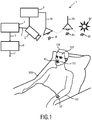
- Fig. 1 shows an exemplary embodiment of a system 1 for determining vital sign information 7 of a subject 100 according to an aspect of the present invention.
- the system 1 comprises a marker 10 for application to the subject 100, a detection unit 2 and an analysis unit 6 as the basic components.
- the system 1 for determining vital sign information 7 of the subject 100 is employed in a clinical setting, where the subject 100 lies in bed 200.
- the marker 10 is configured to change an optical property in response to a physiological process of the subject 100.
- the detection unit 2 is connected to an optional image processing unit 4.
- the detection unit 2 provides radiation data 3 that represents the detected radiation to the image processing unit 4 in form of a video stream.
- the image processing unit 4 identifies the marker 10 in the radiation data 3.
- the image processing unit 4 in turn is connected to the analysis unit 6.
- the image processing unit 4 provides pre-processed radiation data 5 to the analysis unit 6.
- the pre-processed radiation data 5 in this example comprises information about which region of the images of the video stream of the radiation data 3 depict the marker 10.
- the analysis unit 6 determines the vital sign information 7 of the subject 100 from the detected radiation.
- the image processing unit 4 for identifying the marker 10 can also be incorporated into the analysis unit 6.
- the radiation data 3 is directly provided to the analysis unit 6.
- the marker 10 can either be determined by manually selecting the marker 10 in the images of the video stream.
- the subject 100 with the marker 10 has to be located in a predetermined position within the field of view of the detection unit 2 such that the marker 10 is located at a predetermined position.
- an automated identification of the marker 10 in the radiation data 3 by the image processing unit 4 is preferred.
- the marker 10 is directly applied to the bare skin of the nasal/oral region 101 of the subject 100.
- An alternative marker 10' is located at the left forearm 102 of the subject 100.
- the size and shape of the marker 10, 10' can be adapted depending on the anatomic location.
- the system 1 for determining vital sign information 7 of the subject 100 can be further configured as a system for measuring vital signs by remote photo-plethysmography.
- Plethysmography historically refers to the measurement of volume changes of an organ or body part and in particular to the detection of volume changes due to a cardio-vascular pulse wave traveling through the body of the subject 100 with every heartbeat.
- Photo-plethysmography is an optical measurement technique that evaluates a time-variant change of light reflectance or transmission of an area or volume of interest.
- PPG for determining a heart rate is based on the principle that blood absorbs light more than surrounding tissue, so variations in blood volume with every heartbeat affect transmission or reflectance correspondingly.
- Every heartbeat causes small changes in the color of a face of the subject. These changes are not visible to the eye, but the detection unit 2 is configured to detect these "micro-blushes".
- the time-variant color change can be provided as a PPG waveform which is evaluated by the analysis unit 6 to measure the heart rate as the vital sign information 7.
- the PPG waveform can comprise information attributable to further physiological phenomena such as the respiration.
- the transmissivity and/or reflectivity at different wavelengths (typically red and infrared as mentioned before)
- the blood oxygen saturation can be determined.
- the prior art discloses using a thermal imager or alternatively evaluating body movements to determine a respiration rate.
- the present invention suggests to apply a marker to the subject, wherein the marker 10 is configured to change an optical property in response to a physiological process of the subject 100.
- vital sign information gets detectable by a detection unit 2, in particular a low-cost standard CCD sensor.
- the detection unit 2 can also be referred to as a vital signs camera.
- the scenery in Fig. 1 is illuminated by a source of radiation, such as sunlight 8a or an artificial light source 8b.
- the radiation source 8a, 8b directly or indirectly emits radiation 8d, 8e towards the subject 100.
- the system 1 can also comprise an optional system light source 8c that emits light 8f towards the subject 100.
- the use of the system light source 8c is particularly beneficial if the ambient light sources 8a, 8b do not provide sufficient light or if the spectrum of the ambient light sources 8a, 8b does not provide sufficient power in a desired spectral region.
- An optional control unit 9 is adapted to control the sensitivity of the detection unit 2 and/or to control the power of the system light source 8c. Because the dynamic range of detector or image sensor that is used as the detection unit 2 is limited, shutters and electronic offsets may have to be adjusted according to the lighting situation in the observed scene.
- the system light source 8c can be part of a control loop which sets an optimal operating point of the image sensor of the detection unit 2. Optimal in this context refers to an output signal without signal clipping, no saturation of individual detectors of the image sensor and a good signal-to-noise ratio at least for the detection area corresponding to the marker 10, 10'.
- the detection unit 2 comprises a standard image sensor for detecting radiation from the scenery with the marker 10, 10'.
- the detection unit is an off-the-shelf camera operating in a wavelength region between 300 nm to 1400 nm, preferably between 420 nm and 1100 nm, preferably between 420 nm and 750 nm, preferably in the visible range.
- the wavelength region of the detection unit preferably includes at least some near ultraviolet (UV) light and/or some near infrared (IR) light wavelengths.
- UV near ultraviolet
- IR near infrared
- An image sensor as used herein does explicitly not refer to a thermal imager operating in the mid to long infrared wavelength range of 7,500 nm to 14,000 nm.
- the system 1 with the detection unit 2, the analysis unit 6 and the marker 10 can be provided at much lower cost.
- the system light source 8c is configured to emit non-visible radiation 8f, in particular near infrared and/or near ultraviolet light. Thereby, the subject 100 can be monitored at night or darkness in terms of the visible wavelength spectrum, without disturbing the subject 100.
- the system light source 8c is configured to emit light with different spectral properties, for example red and infrared light or red and green light at the same and/or different times to enable a measurement of blood oxygen saturation, as for example disclosed by Wieringa et al. "Contactless Multiple Wavelength Photo-Plethysmographic Imaging: A First Step Towards "SPO2 Camera” Technology", Annals of Biomedical Engineering, vol. 33, No. 8, 2005, pp. 1034-1041 .
- the marker 10 is configured to change an optical property in response to a physiological process of the subject 100.
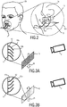
- Fig. 2 shows a close-up of the face of the subject 100, wherein the marker 10 is configured for application to a nasal and/or oral region 101 of the subject, in particular to a region underneath a nose 104 of the subject in the supralabial region, for example spanning across the philtrum.
- the marker 10 is configured to change an optical property due to a mechanical manipulation of the marker 10 caused by a physiological process of the subject 100.
- An exemplary embodiment of such a marker 10 is described with reference to Figs. 3A and 3B .
- a surface 11 of the marker 10 comprises filaments 12 protruding from said surface 11.
- these filaments are flexible filaments, in particular textile fibers that are configured to move upon a stream of air passing by.
- Filaments are not limited to filaments of circular cross-section but also include shapes such as, for example, a lamella structure.
- the inset of Fig. 3A illustrates an orientation of the filaments 12 during exhalation, wherein a flow of exhaled air 20 passes by the surface 11 of the marker during exhalation and bends the filaments 12 downwards.
- the filaments 12 comprise a first surface 12a having a first optical property and a second surface 12b having a second optical property.
- a first optical property for example as shown in Fig. 3A , an upper surface 12a of the filament 12 is black, whereas a lower surface 12b is white.
- the first and second surface can have different color, different reflection or scattering properties.
- the first surface 12a and the second surface 12b have a high contrast. Thus, during exhalation, the detection unit 2 sees a darker color.
- Fig. 3B shows the marker 10 during inhalation, wherein a flow of air 21 passes by the marker surface 11 in an upward direction.
- the filaments 12a are oriented in an upward direction, such that the white side 12b of the filament 12 is visible to the detection unit 2.
- the detection unit 2 which captures a brighter image.
- the analysis unit 6 is configured to evaluate the detected radiation over time and can thus to analyze the change between a darker appearance of the marker 10 as shown in Fig. 3A during exhalation and a brighter appearance of the marker 10 as shown in Fig. 3B during inhalation.
- vital sign information referring to the respiration of the subject, which is invisible itself to the visible optical spectrum, gets detectable by a potentially low-cost detection unit 2.
- a respiratory flow of air 22 does not orient all the filaments 12 of the surface 11 of the marker in the same direction but merely causes a re-orientation, wherein some filaments flex to a right and some filaments flex to a left side.
- absolute knowledge about an orientation of filaments is not mandatory, since a relative change can also be evaluated.
- the period times of a first optical property and a second optical property can be compared. For example, inspiration typically has a shorter duration than expiration. Moreover, expiration is often followed by a breathing pause.
- the analysis unit 6 is configured to derive information about a tidal volume of the subject 100 with a marker as shown in Figs. 3A and 3B .
- the number of filaments that move with the airflow correlates to the breathing strength.
- the color change contains information about the breathing strength over time.
- An integral of the corresponding signal over time correlates to the tidal volume.
- each filament has a color/brightness scale gradient from top to the bottom. The stronger the breathing, the more of each single filament is visible to the detection unit 2. Thus, again the average color/brightness change would be indicative for the breathing strength over time.
- An integral of the corresponding signal over time again correlates with the tidal volume.
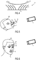
- the marker 10" is indirectly applied to the subject 100.
- the marker 10" is implemented as a part of a tubular system 30 of an intubated patient 100.
- the marker 10" is configured to change its color due to a chemical manipulation of the marker, i.e. in response to a different carbon dioxide concentration of inhaled and exhaled air.
- the color change is observed with the detection unit 2 for detecting radiation from the marker and the corresponding radiation data 3 is provided to the analysis unit 6 for determining the vital sign information 7 of the subject 100 from the detected radiation by evaluating the detected radiation over time.
- an actual value can be used as independent information.
- the system 1 for determining vital sign information as disclosed herein can be combined with colorimetric and/or fluorimetric optical measurements principles known from chemical analytic sensors, for example, to determine oxygen and carbon dioxide concentrations.
- chemical analytic sensors for example, to determine oxygen and carbon dioxide concentrations.
- oxygen concentration there are known principles of dynamic fluorescence quenching or sensors that use the fluorescence of a chemical complex in a sol-gel to measure the partial pressure of oxygen such as Joseph R. Lakowicz, "Principles of Fluorescence Spectroscopy", Third Edition, ISBN: 978-0-387-31278-1 ; Otto S.
- the optical information such as the actual color
- the optical information may be sufficiently accurate for determining a carbon dioxide concentration of inhaled and exhaled air for certain applications.
- a delta value between an inspiration phase and an expiration phase or alternatively a trend thereof can be evaluated if an absolute accuracy is not sufficient.
- Exemplary parameters that can be determined include, but are not limited to exhaled carbon dioxide level, oxygen concentration (inspired and/or expired), oxygen consumption (delta between expired and inspired), oxygen uptake (efficiency indicator for lungs), temperature or temperature difference to ambient temperature, and humidity. This further includes a concentration of chemical substances, in particular chemical substances involved with certain diseases.
- the marker 10" shown in Fig. 5 can be part of the tubular system 30, wherein a color of the tubular system 30 can serve as a reference surface for calibrating the system 1 for determining vital sign information, in particular for calibrating the detection unit 2 to the available light intensity and spectrum.
- information can be encoded in the marker as shown in Fig. 6 in form of a barcode 41.
- the additional information can, for example, be used for calibrating the system 1, for configuring a measurement procedure or for automatically assigning the measured vital sign information to an electronic health record of the subject 100.
- a plurality of markers 10, 40 can be applied to the subject 100.
- the markers can be configured for same or different vital signs to be measured.
- the detection unit 2 is configured correspondingly to detect radiation received from both markers. Furthermore, the detection unit can be configured to determine vital sign information of the subject by directly evaluating a time-variant change of the color of the skin of the subject 100.
- the system for determining vital sign information of a subject comprising a marker for application to the subject, wherein the marker is configured to change an optical property in response to a physiological process of the subject, a detection unit for detecting radiation from the marker, and an analysis unit for determining the vital sign information of the subject from the detected radiation successfully provides a system for unobtrusive monitoring of vital signs at low system cost.
Landscapes
- Health & Medical Sciences (AREA)
- Life Sciences & Earth Sciences (AREA)
- Surgery (AREA)
- Engineering & Computer Science (AREA)
- Veterinary Medicine (AREA)
- Public Health (AREA)
- Pathology (AREA)
- Biomedical Technology (AREA)
- Heart & Thoracic Surgery (AREA)
- Medical Informatics (AREA)
- Molecular Biology (AREA)
- Animal Behavior & Ethology (AREA)
- General Health & Medical Sciences (AREA)
- Physics & Mathematics (AREA)
- Biophysics (AREA)
- Physiology (AREA)
- Pulmonology (AREA)
- Oral & Maxillofacial Surgery (AREA)
- Dentistry (AREA)
- Nuclear Medicine, Radiotherapy & Molecular Imaging (AREA)
- Spectroscopy & Molecular Physics (AREA)
- Otolaryngology (AREA)
- Artificial Intelligence (AREA)
- Computer Vision & Pattern Recognition (AREA)
- Psychiatry (AREA)
- Signal Processing (AREA)
- Measurement Of The Respiration, Hearing Ability, Form, And Blood Characteristics Of Living Organisms (AREA)
- Measuring Pulse, Heart Rate, Blood Pressure Or Blood Flow (AREA)
Priority Applications (1)
| Application Number | Priority Date | Filing Date | Title |
|---|---|---|---|
| EP14789252.5A EP3062701B1 (en) | 2013-11-01 | 2014-10-23 | System and method for determining vital sign information of a subject |
Applications Claiming Priority (4)
| Application Number | Priority Date | Filing Date | Title |
|---|---|---|---|
| US201361898554P | 2013-11-01 | 2013-11-01 | |
| EP13191299 | 2013-11-01 | ||
| PCT/EP2014/072752 WO2015062969A1 (en) | 2013-11-01 | 2014-10-23 | System and method for determining vital sign information of a subject |
| EP14789252.5A EP3062701B1 (en) | 2013-11-01 | 2014-10-23 | System and method for determining vital sign information of a subject |
Publications (2)
| Publication Number | Publication Date |
|---|---|
| EP3062701A1 EP3062701A1 (en) | 2016-09-07 |
| EP3062701B1 true EP3062701B1 (en) | 2021-01-13 |
Family
ID=49517361
Family Applications (1)
| Application Number | Title | Priority Date | Filing Date |
|---|---|---|---|
| EP14789252.5A Active EP3062701B1 (en) | 2013-11-01 | 2014-10-23 | System and method for determining vital sign information of a subject |
Country Status (6)
| Country | Link |
|---|---|
| US (1) | US10602962B2 (enExample) |
| EP (1) | EP3062701B1 (enExample) |
| JP (1) | JP6571074B2 (enExample) |
| CN (1) | CN105705089B (enExample) |
| RU (1) | RU2677006C2 (enExample) |
| WO (1) | WO2015062969A1 (enExample) |
Cited By (1)
| Publication number | Priority date | Publication date | Assignee | Title |
|---|---|---|---|---|
| USD979516S1 (en) | 2020-05-11 | 2023-02-28 | Masimo Corporation | Connector |
Families Citing this family (29)
| Publication number | Priority date | Publication date | Assignee | Title |
|---|---|---|---|---|
| US20150150641A1 (en) * | 2011-10-28 | 2015-06-04 | Navigate Surgical Technologies, Inc. | System and method for determining the three-dimensional location and orientation of identification markers |
| US10524667B2 (en) * | 2015-06-14 | 2020-01-07 | Facense Ltd. | Respiration-based estimation of an aerobic activity parameter |
| US10045699B2 (en) * | 2015-06-14 | 2018-08-14 | Facense Ltd. | Determining a state of a user based on thermal measurements of the forehead |
| US10524696B2 (en) * | 2015-06-14 | 2020-01-07 | Facense Ltd. | Virtual coaching based on respiration signals |
| US9968264B2 (en) * | 2015-06-14 | 2018-05-15 | Facense Ltd. | Detecting physiological responses based on thermal asymmetry of the face |
| DE102016110903A1 (de) * | 2015-06-14 | 2016-12-15 | Facense Ltd. | Head-Mounted-Devices zur Messung physiologischer Reaktionen |
| US10136856B2 (en) * | 2016-06-27 | 2018-11-27 | Facense Ltd. | Wearable respiration measurements system |
| US10154810B2 (en) * | 2015-06-14 | 2018-12-18 | Facense Ltd. | Security system that detects atypical behavior |
| AU2016315947B2 (en) | 2015-08-31 | 2021-02-18 | Masimo Corporation | Wireless patient monitoring systems and methods |
| CN105520724A (zh) * | 2016-02-26 | 2016-04-27 | 严定远 | 一种测量人体心跳速率和呼吸频率的方法 |
| CN105877720A (zh) * | 2016-06-24 | 2016-08-24 | 郭润峰 | 一种人体脉搏及体温监测装置 |
| CN106295161A (zh) * | 2016-08-04 | 2017-01-04 | 合肥寰景信息技术有限公司 | 一种用于健康科普平台的动作捕捉方式 |
| CN106295162A (zh) * | 2016-08-04 | 2017-01-04 | 合肥寰景信息技术有限公司 | 一种基于声波动作捕捉的健康监控系统 |
| EP3678544A4 (en) | 2017-09-05 | 2021-05-19 | Breathevision Ltd. | MONITORING SYSTEM |
| CN110236547B (zh) * | 2018-03-09 | 2022-10-28 | 浙江清华柔性电子技术研究院 | 呼吸频率的检测方法 |
| US11681886B2 (en) * | 2018-09-06 | 2023-06-20 | John P. Peeters | Genomic and environmental blockchain sensors |
| US20200155040A1 (en) | 2018-11-16 | 2020-05-21 | Hill-Rom Services, Inc. | Systems and methods for determining subject positioning and vital signs |
| EP3669764A1 (en) * | 2018-12-19 | 2020-06-24 | Koninklijke Philips N.V. | System and method for determining at least one vital sign of a subject |
| US11678829B2 (en) | 2019-04-17 | 2023-06-20 | Masimo Corporation | Physiological monitoring device attachment assembly |
| USD919100S1 (en) | 2019-08-16 | 2021-05-11 | Masimo Corporation | Holder for a patient monitor |
| USD917704S1 (en) | 2019-08-16 | 2021-04-27 | Masimo Corporation | Patient monitor |
| USD985498S1 (en) | 2019-08-16 | 2023-05-09 | Masimo Corporation | Connector |
| USD919094S1 (en) | 2019-08-16 | 2021-05-11 | Masimo Corporation | Blood pressure device |
| US11448640B2 (en) * | 2019-10-15 | 2022-09-20 | GE Precision Healthcare LLC | Respiratory gas sensor system with color detection |
| USD927699S1 (en) | 2019-10-18 | 2021-08-10 | Masimo Corporation | Electrode pad |
| USD933232S1 (en) | 2020-05-11 | 2021-10-12 | Masimo Corporation | Blood pressure monitor |
| US10881157B1 (en) * | 2020-07-08 | 2021-01-05 | Mawco Tech Inc. | Temperature-reading face shield |
| EP4366620A1 (en) * | 2021-08-26 | 2024-05-15 | St. Jude Medical, Cardiology Division, Inc. | Method and system for generating respiration signals for use in electrophysiology procedures |
| KR102839446B1 (ko) * | 2023-04-10 | 2025-07-29 | 고려대학교 산학협력단 | Ar 기반의 치아 교정 보조 시스템 및 그 운용방법 |
Citations (1)
| Publication number | Priority date | Publication date | Assignee | Title |
|---|---|---|---|---|
| US20070076935A1 (en) * | 1998-10-23 | 2007-04-05 | Andrew Jeung | Method and system for monitoring breathing activity of a subject |
Family Cites Families (22)
| Publication number | Priority date | Publication date | Assignee | Title |
|---|---|---|---|---|
| US4945919A (en) * | 1989-02-10 | 1990-08-07 | Yamaguchi Yakuhin Shokai Ltd. | Rhinological diagnostic device |
| US5241300B1 (en) * | 1992-04-24 | 1995-10-31 | Johannes Buschmann | Sids detection apparatus and methods |
| JP3390802B2 (ja) | 1995-03-28 | 2003-03-31 | 日本光電工業株式会社 | 呼吸モニタ |
| JP3263035B2 (ja) | 1997-11-21 | 2002-03-04 | 東芝エンジニアリング株式会社 | 呼吸モニタリングの関心領域設定装置および呼吸モニタリングシステム |
| GB0110480D0 (en) * | 2001-04-28 | 2001-06-20 | Univ Manchester Metropolitan | Methods and apparatus for analysing the behaviour of a subject |
| US7087027B2 (en) * | 2002-04-22 | 2006-08-08 | Page Thomas C | Device and method for monitoring respiration |
| US20050010697A1 (en) * | 2002-12-30 | 2005-01-13 | Husam Kinawi | System for bandwidth detection and content switching |
| US7381187B2 (en) * | 2003-09-12 | 2008-06-03 | Textronics, Inc. | Blood pressure monitoring system and method of having an extended optical range |
| BRPI0712706A2 (pt) | 2006-06-12 | 2012-07-03 | Koninkl Philips Electronics Nv | cobertura de corpo para apliacação à pele, e, método de comunicar uma variação na temperatura da pele. |
| US8149273B2 (en) | 2007-11-30 | 2012-04-03 | Fuji Xerox Co., Ltd. | System and methods for vital sign estimation from passive thermal video |
| WO2010101625A2 (en) * | 2009-03-02 | 2010-09-10 | Seventh Sense Biosystems, Inc. | Oxygen sensor |
| AU2010240501A1 (en) | 2009-04-23 | 2011-10-06 | Yeda Research And Development Co. Ltd. | Nasal flow device controller |
| US20130030257A1 (en) * | 2010-05-14 | 2013-01-31 | Kai Medical, Inc. | Systems and methods for non-contact multiparameter vital signs monitoring, apnea therapy, apnea diagnosis, and snore therapy |
| ES2387153B1 (es) | 2010-06-16 | 2013-08-08 | Fundación Para La Investigación Biomédica Del Hospital Universitario De La Paz | Sistema y procedimiento para obtener datos acerca del ciclo respiratorio de un paciente |
| CN103503024B (zh) * | 2011-04-14 | 2016-10-05 | 皇家飞利浦有限公司 | 用于从特征信号提取信息的设备和方法 |
| US8790269B2 (en) | 2011-05-09 | 2014-07-29 | Xerox Corporation | Monitoring respiration with a thermal imaging system |
| JP5568061B2 (ja) * | 2011-06-24 | 2014-08-06 | 日本光電工業株式会社 | Co2センサ及びco2測定装置 |
| US8715202B2 (en) | 2011-09-27 | 2014-05-06 | Xerox Corporation | Minimally invasive image-based determination of carbon dioxide (CO2) concentration in exhaled breath |
| DE102012104419B3 (de) | 2012-05-22 | 2013-04-11 | Konrad Wehberg | Vorrichtung und Verfahren zur thermischen Untersuchung der weiblichen Brust |
| EP2858564A1 (en) | 2012-06-12 | 2015-04-15 | Koninklijke Philips N.V. | System for camera-based vital sign measurement |
| EP2762066A1 (en) | 2013-02-05 | 2014-08-06 | Koninklijke Philips N.V. | System and method for determining vital sign information of a subject |
| EP2769667A1 (en) | 2013-02-22 | 2014-08-27 | Koninklijke Philips N.V. | Marker with light emitting area for use in determining vital sign information |
-
2014
- 2014-10-23 WO PCT/EP2014/072752 patent/WO2015062969A1/en not_active Ceased
- 2014-10-23 EP EP14789252.5A patent/EP3062701B1/en active Active
- 2014-10-23 RU RU2016121419A patent/RU2677006C2/ru not_active IP Right Cessation
- 2014-10-23 JP JP2016521959A patent/JP6571074B2/ja active Active
- 2014-10-23 CN CN201480059826.3A patent/CN105705089B/zh active Active
- 2014-10-23 US US14/521,944 patent/US10602962B2/en active Active
Patent Citations (1)
| Publication number | Priority date | Publication date | Assignee | Title |
|---|---|---|---|---|
| US20070076935A1 (en) * | 1998-10-23 | 2007-04-05 | Andrew Jeung | Method and system for monitoring breathing activity of a subject |
Non-Patent Citations (2)
| Title |
|---|
| CORTEN G P: "FLOW SEPARATION ON WIND TURBINE BLADES", THESIS UNIVERSITY OF UTRECHT, XX, XX, 1 January 1987 (1987-01-01), pages VII - XIV,01, XP001164271 * |
| W VERKRUIJSSE; ET AL: "A novel biometric signature: multi-site, remote (> 100 m) photo-plethysmography using ambient light. Technical Note PR-TN 2010/00097", TECHNICAL NOTE PR-TN 2010/00097, 1 March 2010 (2010-03-01), XP055059501, Retrieved from the Internet <URL:http://repository.tudelft.nl/assets/uuid:b2c3fa50-706d-4339-83f1-f6882d0cd91c/tn2010-00097.pdf> [retrieved on 20130412] * |
Cited By (1)
| Publication number | Priority date | Publication date | Assignee | Title |
|---|---|---|---|---|
| USD979516S1 (en) | 2020-05-11 | 2023-02-28 | Masimo Corporation | Connector |
Also Published As
| Publication number | Publication date |
|---|---|
| EP3062701A1 (en) | 2016-09-07 |
| US20150126872A1 (en) | 2015-05-07 |
| US10602962B2 (en) | 2020-03-31 |
| RU2016121419A (ru) | 2017-12-04 |
| JP6571074B2 (ja) | 2019-09-04 |
| CN105705089A (zh) | 2016-06-22 |
| RU2677006C2 (ru) | 2019-01-14 |
| RU2016121419A3 (enExample) | 2018-06-25 |
| JP2017500066A (ja) | 2017-01-05 |
| CN105705089B (zh) | 2019-12-24 |
| WO2015062969A1 (en) | 2015-05-07 |
Similar Documents
| Publication | Publication Date | Title |
|---|---|---|
| EP3062701B1 (en) | System and method for determining vital sign information of a subject | |
| CN104363831B (zh) | 用于基于相机的生命体征测量的系统 | |
| US10660524B2 (en) | System and method for determining vital sign information of a subject | |
| US9999355B2 (en) | Device, system and method for determining vital signs of a subject based on reflected and transmitted light | |
| EP2958485B1 (en) | Marker with light emitting area for use in determining vital sign information | |
| EP2964078B1 (en) | System and method for determining vital sign information | |
| EP3104767B1 (en) | Device, system and method for determining vital signs of a subject based on reflected and transmitted light | |
| EP3479754A1 (en) | Device, system and method for determining at least one vital sign of a subject | |
| EP3247261A1 (en) | Device, system and method for skin detection | |
| US20170014087A1 (en) | Device, system and method for determining vital signs of a subject | |
| EP3226765A1 (en) | Device and method for skin detection | |
| JP6899395B2 (ja) | 対象のバイタルサインを決定するデバイス、システム及び方法 | |
| US20190108650A1 (en) | Method, device and system for enabling to analyze a property of a vital sign detector |
Legal Events
| Date | Code | Title | Description |
|---|---|---|---|
| PUAI | Public reference made under article 153(3) epc to a published international application that has entered the european phase |
Free format text: ORIGINAL CODE: 0009012 |
|
| 17P | Request for examination filed |
Effective date: 20160601 |
|
| AK | Designated contracting states |
Kind code of ref document: A1 Designated state(s): AL AT BE BG CH CY CZ DE DK EE ES FI FR GB GR HR HU IE IS IT LI LT LU LV MC MK MT NL NO PL PT RO RS SE SI SK SM TR |
|
| AX | Request for extension of the european patent |
Extension state: BA ME |
|
| DAX | Request for extension of the european patent (deleted) | ||
| STAA | Information on the status of an ep patent application or granted ep patent |
Free format text: STATUS: EXAMINATION IS IN PROGRESS |
|
| 17Q | First examination report despatched |
Effective date: 20170502 |
|
| RAP1 | Party data changed (applicant data changed or rights of an application transferred) |
Owner name: KONINKLIJKE PHILIPS N.V. |
|
| GRAP | Despatch of communication of intention to grant a patent |
Free format text: ORIGINAL CODE: EPIDOSNIGR1 |
|
| STAA | Information on the status of an ep patent application or granted ep patent |
Free format text: STATUS: GRANT OF PATENT IS INTENDED |
|
| INTG | Intention to grant announced |
Effective date: 20200818 |
|
| GRAS | Grant fee paid |
Free format text: ORIGINAL CODE: EPIDOSNIGR3 |
|
| GRAA | (expected) grant |
Free format text: ORIGINAL CODE: 0009210 |
|
| STAA | Information on the status of an ep patent application or granted ep patent |
Free format text: STATUS: THE PATENT HAS BEEN GRANTED |
|
| AK | Designated contracting states |
Kind code of ref document: B1 Designated state(s): AL AT BE BG CH CY CZ DE DK EE ES FI FR GB GR HR HU IE IS IT LI LT LU LV MC MK MT NL NO PL PT RO RS SE SI SK SM TR |
|
| REG | Reference to a national code |
Ref country code: GB Ref legal event code: FG4D |
|
| REG | Reference to a national code |
Ref country code: CH Ref legal event code: EP |
|
| REG | Reference to a national code |
Ref country code: IE Ref legal event code: FG4D |
|
| REG | Reference to a national code |
Ref country code: DE Ref legal event code: R096 Ref document number: 602014074245 Country of ref document: DE |
|
| REG | Reference to a national code |
Ref country code: AT Ref legal event code: REF Ref document number: 1353932 Country of ref document: AT Kind code of ref document: T Effective date: 20210215 |
|
| REG | Reference to a national code |
Ref country code: AT Ref legal event code: MK05 Ref document number: 1353932 Country of ref document: AT Kind code of ref document: T Effective date: 20210113 |
|
| REG | Reference to a national code |
Ref country code: NL Ref legal event code: MP Effective date: 20210113 |
|
| REG | Reference to a national code |
Ref country code: LT Ref legal event code: MG9D |
|
| PG25 | Lapsed in a contracting state [announced via postgrant information from national office to epo] |
Ref country code: BG Free format text: LAPSE BECAUSE OF FAILURE TO SUBMIT A TRANSLATION OF THE DESCRIPTION OR TO PAY THE FEE WITHIN THE PRESCRIBED TIME-LIMIT Effective date: 20210413 Ref country code: NL Free format text: LAPSE BECAUSE OF FAILURE TO SUBMIT A TRANSLATION OF THE DESCRIPTION OR TO PAY THE FEE WITHIN THE PRESCRIBED TIME-LIMIT Effective date: 20210113 Ref country code: NO Free format text: LAPSE BECAUSE OF FAILURE TO SUBMIT A TRANSLATION OF THE DESCRIPTION OR TO PAY THE FEE WITHIN THE PRESCRIBED TIME-LIMIT Effective date: 20210413 Ref country code: PT Free format text: LAPSE BECAUSE OF FAILURE TO SUBMIT A TRANSLATION OF THE DESCRIPTION OR TO PAY THE FEE WITHIN THE PRESCRIBED TIME-LIMIT Effective date: 20210513 Ref country code: LT Free format text: LAPSE BECAUSE OF FAILURE TO SUBMIT A TRANSLATION OF THE DESCRIPTION OR TO PAY THE FEE WITHIN THE PRESCRIBED TIME-LIMIT Effective date: 20210113 Ref country code: FI Free format text: LAPSE BECAUSE OF FAILURE TO SUBMIT A TRANSLATION OF THE DESCRIPTION OR TO PAY THE FEE WITHIN THE PRESCRIBED TIME-LIMIT Effective date: 20210113 Ref country code: GR Free format text: LAPSE BECAUSE OF FAILURE TO SUBMIT A TRANSLATION OF THE DESCRIPTION OR TO PAY THE FEE WITHIN THE PRESCRIBED TIME-LIMIT Effective date: 20210414 Ref country code: HR Free format text: LAPSE BECAUSE OF FAILURE TO SUBMIT A TRANSLATION OF THE DESCRIPTION OR TO PAY THE FEE WITHIN THE PRESCRIBED TIME-LIMIT Effective date: 20210113 |
|
| PG25 | Lapsed in a contracting state [announced via postgrant information from national office to epo] |
Ref country code: PL Free format text: LAPSE BECAUSE OF FAILURE TO SUBMIT A TRANSLATION OF THE DESCRIPTION OR TO PAY THE FEE WITHIN THE PRESCRIBED TIME-LIMIT Effective date: 20210113 Ref country code: LV Free format text: LAPSE BECAUSE OF FAILURE TO SUBMIT A TRANSLATION OF THE DESCRIPTION OR TO PAY THE FEE WITHIN THE PRESCRIBED TIME-LIMIT Effective date: 20210113 Ref country code: RS Free format text: LAPSE BECAUSE OF FAILURE TO SUBMIT A TRANSLATION OF THE DESCRIPTION OR TO PAY THE FEE WITHIN THE PRESCRIBED TIME-LIMIT Effective date: 20210113 Ref country code: AT Free format text: LAPSE BECAUSE OF FAILURE TO SUBMIT A TRANSLATION OF THE DESCRIPTION OR TO PAY THE FEE WITHIN THE PRESCRIBED TIME-LIMIT Effective date: 20210113 Ref country code: SE Free format text: LAPSE BECAUSE OF FAILURE TO SUBMIT A TRANSLATION OF THE DESCRIPTION OR TO PAY THE FEE WITHIN THE PRESCRIBED TIME-LIMIT Effective date: 20210113 |
|
| PG25 | Lapsed in a contracting state [announced via postgrant information from national office to epo] |
Ref country code: IS Free format text: LAPSE BECAUSE OF FAILURE TO SUBMIT A TRANSLATION OF THE DESCRIPTION OR TO PAY THE FEE WITHIN THE PRESCRIBED TIME-LIMIT Effective date: 20210513 |
|
| REG | Reference to a national code |
Ref country code: DE Ref legal event code: R097 Ref document number: 602014074245 Country of ref document: DE |
|
| PG25 | Lapsed in a contracting state [announced via postgrant information from national office to epo] |
Ref country code: EE Free format text: LAPSE BECAUSE OF FAILURE TO SUBMIT A TRANSLATION OF THE DESCRIPTION OR TO PAY THE FEE WITHIN THE PRESCRIBED TIME-LIMIT Effective date: 20210113 Ref country code: CZ Free format text: LAPSE BECAUSE OF FAILURE TO SUBMIT A TRANSLATION OF THE DESCRIPTION OR TO PAY THE FEE WITHIN THE PRESCRIBED TIME-LIMIT Effective date: 20210113 Ref country code: SM Free format text: LAPSE BECAUSE OF FAILURE TO SUBMIT A TRANSLATION OF THE DESCRIPTION OR TO PAY THE FEE WITHIN THE PRESCRIBED TIME-LIMIT Effective date: 20210113 |
|
| PLBE | No opposition filed within time limit |
Free format text: ORIGINAL CODE: 0009261 |
|
| STAA | Information on the status of an ep patent application or granted ep patent |
Free format text: STATUS: NO OPPOSITION FILED WITHIN TIME LIMIT |
|
| PG25 | Lapsed in a contracting state [announced via postgrant information from national office to epo] |
Ref country code: ES Free format text: LAPSE BECAUSE OF FAILURE TO SUBMIT A TRANSLATION OF THE DESCRIPTION OR TO PAY THE FEE WITHIN THE PRESCRIBED TIME-LIMIT Effective date: 20210113 Ref country code: DK Free format text: LAPSE BECAUSE OF FAILURE TO SUBMIT A TRANSLATION OF THE DESCRIPTION OR TO PAY THE FEE WITHIN THE PRESCRIBED TIME-LIMIT Effective date: 20210113 Ref country code: SK Free format text: LAPSE BECAUSE OF FAILURE TO SUBMIT A TRANSLATION OF THE DESCRIPTION OR TO PAY THE FEE WITHIN THE PRESCRIBED TIME-LIMIT Effective date: 20210113 Ref country code: RO Free format text: LAPSE BECAUSE OF FAILURE TO SUBMIT A TRANSLATION OF THE DESCRIPTION OR TO PAY THE FEE WITHIN THE PRESCRIBED TIME-LIMIT Effective date: 20210113 |
|
| 26N | No opposition filed |
Effective date: 20211014 |
|
| PG25 | Lapsed in a contracting state [announced via postgrant information from national office to epo] |
Ref country code: AL Free format text: LAPSE BECAUSE OF FAILURE TO SUBMIT A TRANSLATION OF THE DESCRIPTION OR TO PAY THE FEE WITHIN THE PRESCRIBED TIME-LIMIT Effective date: 20210113 |
|
| PG25 | Lapsed in a contracting state [announced via postgrant information from national office to epo] |
Ref country code: SI Free format text: LAPSE BECAUSE OF FAILURE TO SUBMIT A TRANSLATION OF THE DESCRIPTION OR TO PAY THE FEE WITHIN THE PRESCRIBED TIME-LIMIT Effective date: 20210113 |
|
| PG25 | Lapsed in a contracting state [announced via postgrant information from national office to epo] |
Ref country code: IT Free format text: LAPSE BECAUSE OF FAILURE TO SUBMIT A TRANSLATION OF THE DESCRIPTION OR TO PAY THE FEE WITHIN THE PRESCRIBED TIME-LIMIT Effective date: 20210113 |
|
| PG25 | Lapsed in a contracting state [announced via postgrant information from national office to epo] |
Ref country code: IS Free format text: LAPSE BECAUSE OF FAILURE TO SUBMIT A TRANSLATION OF THE DESCRIPTION OR TO PAY THE FEE WITHIN THE PRESCRIBED TIME-LIMIT Effective date: 20210513 |
|
| REG | Reference to a national code |
Ref country code: CH Ref legal event code: PL |
|
| REG | Reference to a national code |
Ref country code: BE Ref legal event code: MM Effective date: 20211031 |
|
| PG25 | Lapsed in a contracting state [announced via postgrant information from national office to epo] |
Ref country code: MC Free format text: LAPSE BECAUSE OF FAILURE TO SUBMIT A TRANSLATION OF THE DESCRIPTION OR TO PAY THE FEE WITHIN THE PRESCRIBED TIME-LIMIT Effective date: 20210113 |
|
| PG25 | Lapsed in a contracting state [announced via postgrant information from national office to epo] |
Ref country code: LU Free format text: LAPSE BECAUSE OF NON-PAYMENT OF DUE FEES Effective date: 20211023 Ref country code: BE Free format text: LAPSE BECAUSE OF NON-PAYMENT OF DUE FEES Effective date: 20211031 |
|
| PG25 | Lapsed in a contracting state [announced via postgrant information from national office to epo] |
Ref country code: LI Free format text: LAPSE BECAUSE OF NON-PAYMENT OF DUE FEES Effective date: 20211031 Ref country code: CH Free format text: LAPSE BECAUSE OF NON-PAYMENT OF DUE FEES Effective date: 20211031 |
|
| PG25 | Lapsed in a contracting state [announced via postgrant information from national office to epo] |
Ref country code: IE Free format text: LAPSE BECAUSE OF NON-PAYMENT OF DUE FEES Effective date: 20211023 |
|
| PG25 | Lapsed in a contracting state [announced via postgrant information from national office to epo] |
Ref country code: HU Free format text: LAPSE BECAUSE OF FAILURE TO SUBMIT A TRANSLATION OF THE DESCRIPTION OR TO PAY THE FEE WITHIN THE PRESCRIBED TIME-LIMIT; INVALID AB INITIO Effective date: 20141023 |
|
| PG25 | Lapsed in a contracting state [announced via postgrant information from national office to epo] |
Ref country code: CY Free format text: LAPSE BECAUSE OF FAILURE TO SUBMIT A TRANSLATION OF THE DESCRIPTION OR TO PAY THE FEE WITHIN THE PRESCRIBED TIME-LIMIT Effective date: 20210113 |
|
| PG25 | Lapsed in a contracting state [announced via postgrant information from national office to epo] |
Ref country code: MK Free format text: LAPSE BECAUSE OF FAILURE TO SUBMIT A TRANSLATION OF THE DESCRIPTION OR TO PAY THE FEE WITHIN THE PRESCRIBED TIME-LIMIT Effective date: 20210113 |
|
| PG25 | Lapsed in a contracting state [announced via postgrant information from national office to epo] |
Ref country code: TR Free format text: LAPSE BECAUSE OF FAILURE TO SUBMIT A TRANSLATION OF THE DESCRIPTION OR TO PAY THE FEE WITHIN THE PRESCRIBED TIME-LIMIT Effective date: 20210113 |
|
| PG25 | Lapsed in a contracting state [announced via postgrant information from national office to epo] |
Ref country code: MT Free format text: LAPSE BECAUSE OF FAILURE TO SUBMIT A TRANSLATION OF THE DESCRIPTION OR TO PAY THE FEE WITHIN THE PRESCRIBED TIME-LIMIT Effective date: 20210113 |
|
| PGFP | Annual fee paid to national office [announced via postgrant information from national office to epo] |
Ref country code: DE Payment date: 20251028 Year of fee payment: 12 |
|
| PGFP | Annual fee paid to national office [announced via postgrant information from national office to epo] |
Ref country code: GB Payment date: 20251023 Year of fee payment: 12 |
|
| PGFP | Annual fee paid to national office [announced via postgrant information from national office to epo] |
Ref country code: FR Payment date: 20251027 Year of fee payment: 12 |