EP3062319A1 - Transformer for reducing eddy current losses of coil - Google Patents
Transformer for reducing eddy current losses of coil Download PDFInfo
- Publication number
- EP3062319A1 EP3062319A1 EP15194542.5A EP15194542A EP3062319A1 EP 3062319 A1 EP3062319 A1 EP 3062319A1 EP 15194542 A EP15194542 A EP 15194542A EP 3062319 A1 EP3062319 A1 EP 3062319A1
- Authority
- EP
- European Patent Office
- Prior art keywords
- coil
- transformer
- eddy current
- conductor
- core
- Prior art date
- Legal status (The legal status is an assumption and is not a legal conclusion. Google has not performed a legal analysis and makes no representation as to the accuracy of the status listed.)
- Granted
Links
- 239000004020 conductor Substances 0.000 claims abstract description 46
- 230000004907 flux Effects 0.000 claims abstract description 29
- 239000011810 insulating material Substances 0.000 claims description 8
- 238000010586 diagram Methods 0.000 description 9
- 238000000034 method Methods 0.000 description 4
- 238000001816 cooling Methods 0.000 description 3
- 238000012986 modification Methods 0.000 description 3
- 230000004048 modification Effects 0.000 description 3
- 229910000831 Steel Inorganic materials 0.000 description 2
- 239000010959 steel Substances 0.000 description 2
- RYGMFSIKBFXOCR-UHFFFAOYSA-N Copper Chemical compound [Cu] RYGMFSIKBFXOCR-UHFFFAOYSA-N 0.000 description 1
- 229910000976 Electrical steel Inorganic materials 0.000 description 1
- 229910045601 alloy Inorganic materials 0.000 description 1
- 239000000956 alloy Substances 0.000 description 1
- XAGFODPZIPBFFR-UHFFFAOYSA-N aluminium Chemical compound [Al] XAGFODPZIPBFFR-UHFFFAOYSA-N 0.000 description 1
- 229910052782 aluminium Inorganic materials 0.000 description 1
- 238000005097 cold rolling Methods 0.000 description 1
- 229910052802 copper Inorganic materials 0.000 description 1
- 239000010949 copper Substances 0.000 description 1
- 230000003247 decreasing effect Effects 0.000 description 1
- 239000000463 material Substances 0.000 description 1
- 238000013021 overheating Methods 0.000 description 1
- 239000003973 paint Substances 0.000 description 1
- 238000004804 winding Methods 0.000 description 1
Images





Classifications
-
- H—ELECTRICITY
- H01—ELECTRIC ELEMENTS
- H01F—MAGNETS; INDUCTANCES; TRANSFORMERS; SELECTION OF MATERIALS FOR THEIR MAGNETIC PROPERTIES
- H01F27/00—Details of transformers or inductances, in general
- H01F27/28—Coils; Windings; Conductive connections
- H01F27/30—Fastening or clamping coils, windings, or parts thereof together; Fastening or mounting coils or windings on core, casing, or other support
- H01F27/306—Fastening or mounting coils or windings on core, casing or other support
-
- H—ELECTRICITY
- H01—ELECTRIC ELEMENTS
- H01F—MAGNETS; INDUCTANCES; TRANSFORMERS; SELECTION OF MATERIALS FOR THEIR MAGNETIC PROPERTIES
- H01F27/00—Details of transformers or inductances, in general
- H01F27/34—Special means for preventing or reducing unwanted electric or magnetic effects, e.g. no-load losses, reactive currents, harmonics, oscillations, leakage fields
- H01F27/346—Preventing or reducing leakage fields
-
- H—ELECTRICITY
- H01—ELECTRIC ELEMENTS
- H01F—MAGNETS; INDUCTANCES; TRANSFORMERS; SELECTION OF MATERIALS FOR THEIR MAGNETIC PROPERTIES
- H01F27/00—Details of transformers or inductances, in general
- H01F27/24—Magnetic cores
-
- H—ELECTRICITY
- H01—ELECTRIC ELEMENTS
- H01F—MAGNETS; INDUCTANCES; TRANSFORMERS; SELECTION OF MATERIALS FOR THEIR MAGNETIC PROPERTIES
- H01F27/00—Details of transformers or inductances, in general
- H01F27/28—Coils; Windings; Conductive connections
-
- H—ELECTRICITY
- H01—ELECTRIC ELEMENTS
- H01F—MAGNETS; INDUCTANCES; TRANSFORMERS; SELECTION OF MATERIALS FOR THEIR MAGNETIC PROPERTIES
- H01F27/00—Details of transformers or inductances, in general
- H01F27/28—Coils; Windings; Conductive connections
- H01F27/2823—Wires
-
- H—ELECTRICITY
- H01—ELECTRIC ELEMENTS
- H01F—MAGNETS; INDUCTANCES; TRANSFORMERS; SELECTION OF MATERIALS FOR THEIR MAGNETIC PROPERTIES
- H01F27/00—Details of transformers or inductances, in general
- H01F27/28—Coils; Windings; Conductive connections
- H01F27/32—Insulating of coils, windings, or parts thereof
-
- H—ELECTRICITY
- H01—ELECTRIC ELEMENTS
- H01F—MAGNETS; INDUCTANCES; TRANSFORMERS; SELECTION OF MATERIALS FOR THEIR MAGNETIC PROPERTIES
- H01F27/00—Details of transformers or inductances, in general
- H01F27/34—Special means for preventing or reducing unwanted electric or magnetic effects, e.g. no-load losses, reactive currents, harmonics, oscillations, leakage fields
-
- H—ELECTRICITY
- H01—ELECTRIC ELEMENTS
- H01F—MAGNETS; INDUCTANCES; TRANSFORMERS; SELECTION OF MATERIALS FOR THEIR MAGNETIC PROPERTIES
- H01F27/00—Details of transformers or inductances, in general
- H01F27/34—Special means for preventing or reducing unwanted electric or magnetic effects, e.g. no-load losses, reactive currents, harmonics, oscillations, leakage fields
- H01F2027/348—Preventing eddy currents
Definitions
- the present disclosure relates to a transformer for reducing eddy current losses of a coil, and particularly, to a transformer in which a cut part which is provided by removing a portion of a conductor is provided in each of an upper end and a lower end of a coil, and thus, eddy current losses caused by leakage flux are reduced.
- a high voltage power transformer is an electronic device that is provided in a power system and is supplied with a voltage from a power station to boost and lower the voltage.
- the high voltage power transformer plays an important role in transmitting power to a power consumer.
- a loss of a transformer is represented by a sum of no load loss, load loss, and loss which occurs in an auxiliary device (a fan, a pump, and/or the like).
- the no load loss is loss which occurs in a core configuring a transformer
- the load loss is loss which occurs in a coil, a supporting structure near the coil, a tank, and/or the like.
- FIG. 1 schematically illustrates a cross-sectional view of a core and a coil of a related art transformer.
- FIGS. 2A to 2C illustrate examples of a conductor applied to a coil of the related art transformer.
- FIG. 2A illustrates a flat conductor 4a
- FIG. 2B illustrates a double conductor 4b
- FIG. 2C illustrates a transposed conductor 4c.
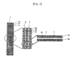
- FIG. 3 illustrates a detailed cross-sectional view of a coil of the related art transformer.
- FIG. 1 a plurality of coils 2 and 3 are disposed to form a concentric circle with respect to a coil 1.
- FIG. 1 only two coils 2 and 3 are illustrated, but the number of coils may be two or more depending on a place where the transformer is used.
- the coils 2 and 3 of the transformer are manufactured by winding the conductors 4 formed of copper, aluminum, and an alloy.
- the conductors 4 are surrounded by an insulating material 5, for insulating turns of the conductors 4.
- FIG. 3 illustrates various forms of conductors used for the coils 2 and 3 of the transformer. An obliquely-striped portion refers to the conductor 4, and a portion surrounding the conductor 4 refers to an insulating material.
- the coil 2 of the transformer is configured by a combination of several pieces of conductors (for example, a combination of sections 2a, 2b, 2c, ... where the transposed conductor 4c is wound).
- a vertical cooling duct 7 may be provided in the coil sections 2a, 2b, 2c, ....
- FIG. 3 illustrates a coil where the transposed conductor 4c is used and two vertical cooling ducts 7 are applied for cooling the coil 2.
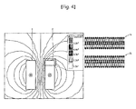
- FIG. 4 illustrates leakage flux of a transformer coil and eddy current loss of a coil end caused by the leakage flux.
- a voltage is induced to a secondary coil 3, and a direction of a current flowing in the secondary coil 3 is opposite to that of a current flowing in the primary coil 2. Due to such an influence, leakage flux largely occurs between the primary coil 2 and the secondary coil 3, and thus, an eddy current is generated near each of the coils 2 and 3, for attenuating the leakage flux. Loss caused by the eddy current is referred to as eddy current loss.
- the eddy current loss is affected by a level and a direction of leakage flux of a transformer, a dimension of a coil conductor, a current density of a coil, a resistance of a coil, and a power frequency.
- a portion where a number of eddy current losses caused by leakage flux occurs is an end of a transformer coil, and a local temperature rise (hot-spot) caused by eddy current loss is high measured.
- an eddy current loss of a coil section 3a is larger than that of a coil section 3b.
- examples of factors affecting the magnitude of eddy current loss which occurs in a coil include a maximum value of leakage flux, an incident direction of leakage flux with respect to a coil, a dimension based on a shape and a size of a coil conductor, a current density of a coil, a resistance of a conductor, and a level of a power frequency.
- a factor for satisfying characteristic (% impedance, a capacity, and/or the like) required by a transformer and adjusting eddy current loss is the dimension of the coil conductor (a, a', a", or be in FIG. 2 ).
- the double conductor 4b is used instead of the flat conductor 4a, and the transposed conductor 4c is used instead of the double conductor 4b.
- a dimension (a) which the most largely affects an eddy current loss of a coil is illustrated in FIG. 2 .
- the transposed conductor 4c where the dimension (a) of the coil conductor is the smallest is used for reducing eddy current losses.
- a method of reducing eddy current losses by adjusting a dimension of a coil conductor has a drawback which is difficult to apply for maintaining mechanical strength. Also, it is required to maintain an appropriate current density of a coil, and thus, a dimension (b) of the conductor should be relatively enlarged for decreasing the dimension (a) of the conductor. For this reason, eddy current loss caused by the dimension (b) increases.
- an aspect of the detailed description is to provide a transformer for reducing eddy current losses caused by leakage flux occurring in the transformer.
- a transformer for reducing eddy current losses of a coil includes: a core; and a first coil and a second coil sequentially installed on a concentric circle to surround the core, wherein a cut part which is provided by removing a portion of a conductor is provided at each of a first outer upper end and a first outer lower end of the first coil and a second inner upper end and a second inner lower end of the second coil to reduce an influence of leakage flux.
- a cut part which is provided by removing a portion of a conductor may be provided at each of a first inner upper end and a first inner lower end of the first coil and a second outer upper end and a second outer lower end of the second coil to reduce an influence of leakage flux.
- a cut surface of the cut part may include one of an inclined surface, a round surface, and a stepped surface.
- an insulating material may be disposed in the cut part.
- the stepped surface may be provided by adjusting a length of a coil section configuring a layer of each of the first coil and the second coil.
- FIG. 5 is a schematic diagram illustrating cross-sectional surfaces of a core and a coil of a transformer according to an exemplary embodiment of the present invention.
- the transformer for reducing eddy current losses of a coil, according to an exemplary embodiment of the present invention, will be described in detail with reference to the accompanying drawings.
- the transformer for reducing eddy current losses of a coil may include a core 10; a first coil 21 and a second coil 26 that are sequentially installed on a concentric circle to surround the core 10.
- a cut part which is provided by removing a portion of a conductor 31 may be provided at each of a first outer upper end 22 and a first outer lower end 3 of the first coil 21 and a second inner upper end 29 and a second inner lower end 30 of the second coil 26.
- the core 10 may be provided to form a flux path and increase a flux density.
- a material of the core 10 may use a directional silicon steel plate manufactured by a cold rolling method.
- the core 10 may be surrounded by an insulating tape which is good in thermal characteristic and mechanical characteristic, and anticorrosive paint processing may be performed for a surface of the core 10.
- the core 10 may be manufactured by stacking steel plates having the same size.
- the stacked steel plates may configure a layer constituting one group.
- a plurality of the layers may be stacked to configure the core 10.
- a coil 20 may be installed around the core 10 to surround the core 10 in a concentric shape.
- a coil which is the most adjacent to the core 10 may be referred to as the first coil 21, and a core which is subsequently installed may be referred to as the second coil 26.
- the coil 20 may be configured by a more number of layers, but for convenience, two coils will be described as an example. A description of the present embodiment and a description of another exemplary embodiment may be applied to three or more coils.
- a plurality of ends constituting corners of the first coil 21 may be respectively referred to as the first outer upper end 22, the first outer lower end 3, a first inner upper end 24, and a first inner lower end 25.
- a plurality of ends constituting corners of the second coil 26 may be respectively referred to as a second outer upper end 27, a second outer lower end 28, the second inner upper end 29, and the second inner lower end 30.
- the coil 20 may be provided so that a portion of a conductor corresponding to an end of the coil 20, where an eddy current loss of the coil 20 occurs the most largely, is removed. That is, the cut part may be provided at each of the first outer upper end 22 and the first outer lower end 3 of the first coil 21 and the second inner upper end 29 and the second inner lower end 30 of the second coil 26.
- the cut part may be provided to have an inclined surface.
- the cut part may be provided in a round shape.
- a cut surface of each end is provided as an inclined surface or provided in a round shape, a surface similar to the form of leakage flux may be provided, and thus, eddy current losses are minimized by avoiding a portion on which leakage fluxes are concentrated. That is, referring to FIG.
- eddy current loss that affects a coil of a transformer increases according to a size of a vector that enters from a coil end into a coil conductor in a vertical direction among leakage fluxes, and in this case, since a cut part is provided at an end of a coil, a level of leakage flux that affects a coil end conductor is lowered.
- FIG. 6 is a schematic diagram illustrating cross-sectional surfaces of a core and a coil of a transformer according to another exemplary embodiment of the present invention.
- a plurality of cut parts may be respectively provided at all ends of each of a plurality of coils. That is, a plurality of cut parts may be respectively provided at a first outer upper end 22, a first outer lower end 23, a first inner upper end 24, and a first inner lower end 25 of a first coil 21. Also, a plurality of cut parts may be respectively provided at a second outer upper end 27, a second outer lower end 28, a second inner upper end 29, and a second inner lower end 30 of a second coil 26. Since a plurality of cut parts are respectively provided at all ends of each of a plurality of coils 20, an eddy current caused by leakage flux is reduced as much as possible.
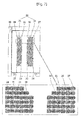
- FIG. 7 illustrates a schematic diagram illustrating cross-sectional surfaces of a core and a coil of a transformer according to another exemplary embodiment of the present invention.
- a cut part which is provided at each of ends of each of a plurality of coils may be provided to have a stepped surface, namely, a stepped shape.
- a stepped surface namely, a stepped shape.
- a unit configuring each of the first coil 21 and the second coil 22 is the conductor 31, and thus, when each of a plurality of coils 20 is manufactured by a method of removing the conductor 31, the cut part may be provided in a stepped shape as illustrated in FIG. 7 .
- the stepped surface may be provided by adjusting a length of a coil section configuring a layer of each of a plurality of coils.
- FIG. 8 is a schematic diagram illustrating cross-sectional surfaces of a core and a coil of a transformer according to another exemplary embodiment of the present invention.
- an insulating material 35 may be filled into a cut part which is provided by removing a conductor 31.
- the conductor 31 may be removed from an end of each of the first coil 21 and the second coil 26, and the insulating material 35 may be filled into a corresponding part. Therefore, eddy current losses caused by leakage flux are reduced, and a shape of the coil 20 is maintained. Accordingly, short circuit strength is not weakened.
Landscapes
- Engineering & Computer Science (AREA)
- Power Engineering (AREA)
- Coils Of Transformers For General Uses (AREA)
- General Induction Heating (AREA)
Abstract
Description
- The present disclosure relates to a transformer for reducing eddy current losses of a coil, and particularly, to a transformer in which a cut part which is provided by removing a portion of a conductor is provided in each of an upper end and a lower end of a coil, and thus, eddy current losses caused by leakage flux are reduced.
- Generally, a high voltage power transformer is an electronic device that is provided in a power system and is supplied with a voltage from a power station to boost and lower the voltage. The high voltage power transformer plays an important role in transmitting power to a power consumer.
- Electrical loss occur in operating and managing a transformer, and a loss of a transformer is represented by a sum of no load loss, load loss, and loss which occurs in an auxiliary device (a fan, a pump, and/or the like). The no load loss is loss which occurs in a core configuring a transformer, and the load loss is loss which occurs in a coil, a supporting structure near the coil, a tank, and/or the like.
- In the load loss, most of losses are direct current (DC) resistance losses caused by a coil resistance, but stray load loss and eddy current loss which occurs in a coil, a supporting structure, and a tank due to leakage flux cannot be neglected. In particular, eddy current loss which occurs in a coil causes local overheating, and is a factor that largely affects long-time operation reliability of a transformer.
-
FIG. 1 schematically illustrates a cross-sectional view of a core and a coil of a related art transformer.FIGS. 2A to 2C illustrate examples of a conductor applied to a coil of the related art transformer. Here,FIG. 2A illustrates aflat conductor 4a,FIG. 2B illustrates adouble conductor 4b, andFIG. 2C illustrates atransposed conductor 4c.FIG. 3 illustrates a detailed cross-sectional view of a coil of the related art transformer. - In the related art transformer, as illustrated in
FIG. 1 , a plurality ofcoils coil 1. InFIG. 1 , only twocoils - The
coils insulating material 5, for insulating turns of the conductors 4.FIG. 3 illustrates various forms of conductors used for thecoils - Referring to
FIG. 3 , thecoil 2 of the transformer is configured by a combination of several pieces of conductors (for example, a combination ofsections conductor 4c is wound). In order to cool thecoil 2, avertical cooling duct 7 may be provided in thecoil sections FIG. 3 illustrates a coil where the transposedconductor 4c is used and twovertical cooling ducts 7 are applied for cooling thecoil 2. -
FIG. 4 illustrates leakage flux of a transformer coil and eddy current loss of a coil end caused by the leakage flux. When power is applied to aprimary coil 2 of a transformer, a voltage is induced to asecondary coil 3, and a direction of a current flowing in thesecondary coil 3 is opposite to that of a current flowing in theprimary coil 2. Due to such an influence, leakage flux largely occurs between theprimary coil 2 and thesecondary coil 3, and thus, an eddy current is generated near each of thecoils FIG. 4 , an eddy current loss of a coil section 3a is larger than that of acoil section 3b. - As described above, examples of factors affecting the magnitude of eddy current loss which occurs in a coil include a maximum value of leakage flux, an incident direction of leakage flux with respect to a coil, a dimension based on a shape and a size of a coil conductor, a current density of a coil, a resistance of a conductor, and a level of a power frequency. In these factors, a factor for satisfying characteristic (% impedance, a capacity, and/or the like) required by a transformer and adjusting eddy current loss is the dimension of the coil conductor (a, a', a", or be in
FIG. 2 ). Generally, in order to reduce eddy current losses of a coil, thedouble conductor 4b is used instead of theflat conductor 4a, and the transposedconductor 4c is used instead of thedouble conductor 4b. In coil dimensions, a dimension (a) which the most largely affects an eddy current loss of a coil is illustrated inFIG. 2 . - Therefore, the transposed
conductor 4c where the dimension (a) of the coil conductor is the smallest is used for reducing eddy current losses. - However, in the related art, a method of reducing eddy current losses by adjusting a dimension of a coil conductor has a drawback which is difficult to apply for maintaining mechanical strength. Also, it is required to maintain an appropriate current density of a coil, and thus, a dimension (b) of the conductor should be relatively enlarged for decreasing the dimension (a) of the conductor. For this reason, eddy current loss caused by the dimension (b) increases.
- Therefore, an aspect of the detailed description is to provide a transformer for reducing eddy current losses caused by leakage flux occurring in the transformer.
- To achieve these and other advantages and in accordance with the purpose of this specification, as embodied and broadly described herein, a transformer for reducing eddy current losses of a coil includes: a core; and a first coil and a second coil sequentially installed on a concentric circle to surround the core, wherein a cut part which is provided by removing a portion of a conductor is provided at each of a first outer upper end and a first outer lower end of the first coil and a second inner upper end and a second inner lower end of the second coil to reduce an influence of leakage flux.
- Here, a cut part which is provided by removing a portion of a conductor may be provided at each of a first inner upper end and a first inner lower end of the first coil and a second outer upper end and a second outer lower end of the second coil to reduce an influence of leakage flux.
- Moreover, a cut surface of the cut part may include one of an inclined surface, a round surface, and a stepped surface.
- Moreover, an insulating material may be disposed in the cut part.
- Moreover, the stepped surface may be provided by adjusting a length of a coil section configuring a layer of each of the first coil and the second coil.
- In the transformed for reducing eddy current losses of a coil according to an exemplary embodiment of the present invention, since a cut part is provided at an end of a coil, eddy current losses caused by leakage flux occurring in the transformer are reduced. Therefore, heat is reduced, and thus, a stability of a device is enhanced, and durability increases. Also, since an insulating material is filled into the cut part, short circuit strength is not weakened.
- Further scope of applicability of the present application will become more apparent from the detailed description given hereinafter. However, it should be understood that the detailed description and specific examples, while indicating preferred embodiments of the disclosure, are given by way of illustration only, since various changes and modifications within the spirit and scope of the disclosure will become apparent to those skilled in the art from the detailed description.
- The accompanying drawings, which are included to provide a further understanding of the disclosure and are incorporated in and constitute a part of this specification, illustrate exemplary embodiments and together with the description serve to explain the principles of the disclosure.
- In the drawings:
-
FIG. 1 schematically illustrates a cross-sectional view of a core and a coil of a related art transformer; -
FIGS. 2A to 2C illustrate examples of a conductor applied to a coil of the related art transformer,FIG. 2A illustrating a flat conductor,FIG. 2B illustrating a double conductor, andFIG. 2C illustrating a transposed conductor; -
FIG. 3 illustrates a detailed cross-sectional view of a coil of the related art transformer; -
FIG. 4 illustrates leakage flux and eddy current loss which occur in a primary coil and a secondary coil of the related art transformer; -
FIG. 5 is a schematic diagram illustrating cross-sectional surfaces of a core and a coil of a transformer according to an exemplary embodiment of the present invention; -
FIG. 6 is a schematic diagram illustrating cross-sectional surfaces of a core and a coil of a transformer according to another exemplary embodiment of the present invention; -
FIG. 7 is a schematic diagram illustrating cross-sectional surfaces of a core and a coil of a transformer according to another exemplary embodiment of the present invention; and -
FIG. 8 is a schematic diagram illustrating cross-sectional surfaces of a core and a coil of a transformer according to another exemplary embodiment of the present invention. - Description will now be given in detail of the exemplary embodiments, with reference to the accompanying drawings. For the sake of brief description with reference to the drawings, the same or equivalent components will be provided with the same reference numbers, and description thereof will not be repeated.
- Hereinafter, preferred embodiments of the present invention will be described in detail with reference to the accompanying drawings. However, the embodiments are provided only to disclose the invention in a manner sufficiently clear and complete for the invention to be easily carried out by a person having ordinary skill in the art to which the invention pertains, but do not mean to limit technical ideas and categories of the present invention.
-
FIG. 5 is a schematic diagram illustrating cross-sectional surfaces of a core and a coil of a transformer according to an exemplary embodiment of the present invention. The transformer for reducing eddy current losses of a coil, according to an exemplary embodiment of the present invention, will be described in detail with reference to the accompanying drawings. - The transformer for reducing eddy current losses of a coil, according to an exemplary embodiment of the present invention, may include a
core 10; afirst coil 21 and asecond coil 26 that are sequentially installed on a concentric circle to surround thecore 10. A cut part which is provided by removing a portion of aconductor 31 may be provided at each of a first outerupper end 22 and a first outerlower end 3 of thefirst coil 21 and a second innerupper end 29 and a second innerlower end 30 of thesecond coil 26. - The core 10 may be provided to form a flux path and increase a flux density. A material of the core 10 may use a directional silicon steel plate manufactured by a cold rolling method. The core 10 may be surrounded by an insulating tape which is good in thermal characteristic and mechanical characteristic, and anticorrosive paint processing may be performed for a surface of the
core 10. - The core 10 may be manufactured by stacking steel plates having the same size. The stacked steel plates may configure a layer constituting one group. A plurality of the layers may be stacked to configure the
core 10. - A
coil 20 may be installed around thecore 10 to surround the core 10 in a concentric shape. A coil which is the most adjacent to the core 10 may be referred to as thefirst coil 21, and a core which is subsequently installed may be referred to as thesecond coil 26. Thecoil 20 may be configured by a more number of layers, but for convenience, two coils will be described as an example. A description of the present embodiment and a description of another exemplary embodiment may be applied to three or more coils. - In a cross-sectional view, a plurality of ends constituting corners of the
first coil 21 may be respectively referred to as the first outerupper end 22, the first outerlower end 3, a first innerupper end 24, and a first innerlower end 25. - Likewise, in the cross-sectional view, a plurality of ends constituting corners of the
second coil 26 may be respectively referred to as a second outerupper end 27, a second outerlower end 28, the second innerupper end 29, and the second innerlower end 30. - The
coil 20 may be provided so that a portion of a conductor corresponding to an end of thecoil 20, where an eddy current loss of thecoil 20 occurs the most largely, is removed. That is, the cut part may be provided at each of the first outerupper end 22 and the first outerlower end 3 of thefirst coil 21 and the second innerupper end 29 and the second innerlower end 30 of thesecond coil 26. - Since the cut part is provided at each of the first outer
upper end 22 and the first outerlower end 3 of thefirst coil 21 and the second innerupper end 29 and the second innerlower end 30 of thesecond coil 26, eddy current losses caused by leakage flux occurring in each of the ends are reduced. - Here, as illustrated in
FIG. 5 , the cut part may be provided to have an inclined surface. Alternatively, although not separately shown, the cut part may be provided in a round shape. When a cut surface of each end is provided as an inclined surface or provided in a round shape, a surface similar to the form of leakage flux may be provided, and thus, eddy current losses are minimized by avoiding a portion on which leakage fluxes are concentrated. That is, referring toFIG. 4 , eddy current loss that affects a coil of a transformer increases according to a size of a vector that enters from a coil end into a coil conductor in a vertical direction among leakage fluxes, and in this case, since a cut part is provided at an end of a coil, a level of leakage flux that affects a coil end conductor is lowered. -
FIG. 6 is a schematic diagram illustrating cross-sectional surfaces of a core and a coil of a transformer according to another exemplary embodiment of the present invention. - In the present embodiment, a plurality of cut parts may be respectively provided at all ends of each of a plurality of coils. That is, a plurality of cut parts may be respectively provided at a first outer
upper end 22, a first outerlower end 23, a first innerupper end 24, and a first innerlower end 25 of afirst coil 21. Also, a plurality of cut parts may be respectively provided at a second outerupper end 27, a second outerlower end 28, a second innerupper end 29, and a second innerlower end 30 of asecond coil 26. Since a plurality of cut parts are respectively provided at all ends of each of a plurality ofcoils 20, an eddy current caused by leakage flux is reduced as much as possible. -
FIG. 7 illustrates a schematic diagram illustrating cross-sectional surfaces of a core and a coil of a transformer according to another exemplary embodiment of the present invention. - In the present embodiment, a cut part which is provided at each of ends of each of a plurality of coils may be provided to have a stepped surface, namely, a stepped shape. This can be clearly seen with reference to a substantial configuration of each of a plurality of
conductors 31 configuring afirst coil 21 and asecond coil 26 illustrated in a detailed diagram. A unit configuring each of thefirst coil 21 and thesecond coil 22 is theconductor 31, and thus, when each of a plurality ofcoils 20 is manufactured by a method of removing theconductor 31, the cut part may be provided in a stepped shape as illustrated inFIG. 7 . - Here, the stepped surface may be provided by adjusting a length of a coil section configuring a layer of each of a plurality of coils.
-
FIG. 8 is a schematic diagram illustrating cross-sectional surfaces of a core and a coil of a transformer according to another exemplary embodiment of the present invention. - In the present embodiment, in each of a plurality of
coils 20, an insulatingmaterial 35 may be filled into a cut part which is provided by removing aconductor 31. Theconductor 31 may be removed from an end of each of thefirst coil 21 and thesecond coil 26, and the insulatingmaterial 35 may be filled into a corresponding part. Therefore, eddy current losses caused by leakage flux are reduced, and a shape of thecoil 20 is maintained. Accordingly, short circuit strength is not weakened. - In the transformed for reducing eddy current losses of a coil according to an exemplary embodiment of the present invention, since a cut part is provided at an end of a coil, eddy current losses caused by leakage flux occurring in the transformer are reduced. Therefore, heat is reduced, and thus, a stability of a device is enhanced, and durability increases. Also, since an insulating material is filled into the cut part, short circuit strength is not weakened.
- The foregoing embodiments and advantages are merely exemplary and are not to be considered as limiting the present disclosure. The present teachings can be readily applied to other types of apparatuses. This description is intended to be illustrative, and not to limit the scope of the claims. Many alternatives, modifications, and variations will be apparent to those skilled in the art. The features, structures, methods, and other characteristics of the exemplary embodiments described herein may be combined in various ways to obtain additional and/or alternative exemplary embodiments.
- As the present features may be embodied in several forms without departing from the characteristics thereof, it should also be understood that the above-described embodiments are not limited by any of the details of the foregoing description, unless otherwise specified, but rather should be considered broadly within its scope as defined in the appended claims, and therefore all changes and modifications that fall within the metes and bounds of the claims, or equivalents of such metes and bounds are therefore intended to be embraced by the appended claims.
Claims (5)
- A transformer for reducing eddy current losses of a coil, the transformer comprising:a core (10); anda first coil (21) and a second coil (26) sequentially installed on a concentric circle to surround the core (10),wherein a cut part which is provided by removing a portion of a conductor (31) is provided at each of a first outer upper end (22) and a first outer lower end (23) of the first coil (21) and a second inner upper end (29) and a second inner lower end (30) of the second coil (26) to reduce an influence of leakage flux.
- The transformer of claim 1, wherein a cut part which is provided by removing a portion of a conductor (31) is provided at each of a first inner upper end (24) and a first inner lower end (25) of the first coil (21) and a second outer upper end (27) and a second outer lower end (28) of the second coil (26) to reduce an influence of leakage flux.
- The transformer of claim 1 or 2, wherein a cut surface of the cut part comprises one of an inclined surface, a round surface, and a stepped surface.
- The transformer of claim 1 or 2, wherein an insulating material (35) is disposed in the cut part.
- The transformer of claim 3, wherein the stepped surface is provided by adjusting a length of a coil section configuring a layer of each of the first coil (21) and the second coil (26).
Applications Claiming Priority (1)
| Application Number | Priority Date | Filing Date | Title |
|---|---|---|---|
| KR1020150025969A KR20160103438A (en) | 2015-02-24 | 2015-02-24 | Transformer reduced of Eddy Current Losses of Winding |
Publications (2)
| Publication Number | Publication Date |
|---|---|
| EP3062319A1 true EP3062319A1 (en) | 2016-08-31 |
| EP3062319B1 EP3062319B1 (en) | 2019-12-25 |
Family
ID=54542116
Family Applications (1)
| Application Number | Title | Priority Date | Filing Date |
|---|---|---|---|
| EP15194542.5A Active EP3062319B1 (en) | 2015-02-24 | 2015-11-13 | Transformer for reducing eddy current losses of coil |
Country Status (6)
| Country | Link |
|---|---|
| US (1) | US10283260B2 (en) |
| EP (1) | EP3062319B1 (en) |
| JP (1) | JP2016157915A (en) |
| KR (1) | KR20160103438A (en) |
| CN (1) | CN105914017A (en) |
| ES (1) | ES2775602T3 (en) |
Families Citing this family (4)
| Publication number | Priority date | Publication date | Assignee | Title |
|---|---|---|---|---|
| KR101997981B1 (en) * | 2017-10-19 | 2019-07-08 | 박훈양 | Transformer type tie-plate for reduced stray loss, and manufacturing method thereof |
| KR102222128B1 (en) * | 2019-07-29 | 2021-03-03 | 현대일렉트릭앤에너지시스템(주) | Transformer with reduced eddy current and Calculation method of eddy current |
| CN114597032B (en) * | 2022-03-09 | 2026-01-02 | 吴江变压器有限公司 | Transformers using composite conductor coils and connection methods of composite conductors |
| CN116108721B (en) * | 2023-02-22 | 2025-02-28 | 中国科学院电工研究所 | An optimization design method for nanocrystalline high-frequency transformer with low eddy current loss |
Citations (4)
| Publication number | Priority date | Publication date | Assignee | Title |
|---|---|---|---|---|
| CH474136A (en) * | 1966-06-02 | 1969-06-15 | Texaco Development Corp | High voltage winding for a high voltage induction device |
| JPS56147417A (en) * | 1980-04-18 | 1981-11-16 | Hitachi Ltd | Winding for transformer or the like |
| JPS60103604A (en) * | 1983-11-10 | 1985-06-07 | Fuji Electric Co Ltd | Multi-parallel windings having large-current capacity of transformer |
| JPS61288406A (en) * | 1985-06-17 | 1986-12-18 | Toshiba Corp | Stationary induction machine |
Family Cites Families (10)
| Publication number | Priority date | Publication date | Assignee | Title |
|---|---|---|---|---|
| JPS5476963A (en) | 1977-12-02 | 1979-06-20 | Hitachi Ltd | Airrcore reactor |
| JPS56152219A (en) | 1980-04-28 | 1981-11-25 | Toshiba Corp | Core type large capacity transformer |
| JPH0651248B2 (en) | 1983-11-07 | 1994-07-06 | 三菱重工業株式会社 | High precision machining method for NC gear shaper |
| JPS6099519U (en) * | 1983-12-14 | 1985-07-06 | 三菱電機株式会社 | reactor |
| JP3332268B2 (en) | 1993-07-27 | 2002-10-07 | 松下電工株式会社 | Thermal storage floor heating system |
| JPH0742959U (en) * | 1993-12-29 | 1995-08-11 | 愛知電機株式会社 | Multi-step board winding |
| JPH09120922A (en) | 1995-10-24 | 1997-05-06 | Fuji Electric Co Ltd | Dislocation conductor winding |
| JPH1187154A (en) | 1997-09-11 | 1999-03-30 | Meidensha Corp | Transformer |
| JP2003224016A (en) | 2002-01-31 | 2003-08-08 | Toshiba Corp | Stationary induction electrical equipment and its updating method |
| US20150109084A1 (en) * | 2013-10-17 | 2015-04-23 | Intellitronix Corporation | Automobile Ignition with Improved Coil Configuration |
-
2015
- 2015-02-24 KR KR1020150025969A patent/KR20160103438A/en not_active Ceased
- 2015-10-16 US US14/885,930 patent/US10283260B2/en active Active
- 2015-10-28 JP JP2015211784A patent/JP2016157915A/en active Pending
- 2015-11-13 EP EP15194542.5A patent/EP3062319B1/en active Active
- 2015-11-13 ES ES15194542T patent/ES2775602T3/en active Active
-
2016
- 2016-01-29 CN CN201610065988.9A patent/CN105914017A/en active Pending
Patent Citations (4)
| Publication number | Priority date | Publication date | Assignee | Title |
|---|---|---|---|---|
| CH474136A (en) * | 1966-06-02 | 1969-06-15 | Texaco Development Corp | High voltage winding for a high voltage induction device |
| JPS56147417A (en) * | 1980-04-18 | 1981-11-16 | Hitachi Ltd | Winding for transformer or the like |
| JPS60103604A (en) * | 1983-11-10 | 1985-06-07 | Fuji Electric Co Ltd | Multi-parallel windings having large-current capacity of transformer |
| JPS61288406A (en) * | 1985-06-17 | 1986-12-18 | Toshiba Corp | Stationary induction machine |
Also Published As
| Publication number | Publication date |
|---|---|
| KR20160103438A (en) | 2016-09-01 |
| US20160247629A1 (en) | 2016-08-25 |
| US10283260B2 (en) | 2019-05-07 |
| ES2775602T3 (en) | 2020-07-27 |
| EP3062319B1 (en) | 2019-12-25 |
| CN105914017A (en) | 2016-08-31 |
| JP2016157915A (en) | 2016-09-01 |
Similar Documents
| Publication | Publication Date | Title |
|---|---|---|
| US8928441B2 (en) | Liquid cooled magnetic component with indirect cooling for high frequency and high power applications | |
| US9355770B2 (en) | Transformer with improved power handling capacity | |
| KR102745695B1 (en) | Inductors, devices having inductors and methods for manufacturing inductors | |
| EP3062319B1 (en) | Transformer for reducing eddy current losses of coil | |
| RU2374713C2 (en) | Planar high-voltage transformer | |
| KR20110027198A (en) | Water-cooled transformer | |
| JP2013501369A (en) | Current compensation choke and method of manufacturing current compensation choke | |
| US12500027B2 (en) | Wound core | |
| US20180218826A1 (en) | Magnetic core, and choke or transformer having such a magnetic core | |
| KR101984464B1 (en) | Transformer and power converter with it | |
| KR102009746B1 (en) | Manufacturing method of the winding coil for the transformer | |
| JP2016039322A (en) | Coil and coil component | |
| JP4838842B2 (en) | Transformer having laminated winding structure | |
| US20130187738A1 (en) | Electrical apparatus having a thermally conductive bobbin | |
| KR101573813B1 (en) | Low loss type hybrid transformer, and manufacturing method thereof | |
| JP7204954B2 (en) | stationary inductor | |
| JP7269699B2 (en) | core, transformer | |
| KR200486562Y1 (en) | Oil immersed transformer having magnetic shield | |
| US10840004B2 (en) | Reducing reluctance in magnetic devices | |
| US20230033439A1 (en) | Electrotechnical device for an aircraft | |
| Chaw et al. | Design comparison for rectangular and round winding distribution transformer (1000 kVA) | |
| US11942254B2 (en) | Transformer insulation modification | |
| CN112655059B (en) | Leakage reactance board for power transformer | |
| JP2001244108A (en) | Superconducting coils for induction equipment | |
| KR102555275B1 (en) | iron core structure of transformer |
Legal Events
| Date | Code | Title | Description |
|---|---|---|---|
| PUAI | Public reference made under article 153(3) epc to a published international application that has entered the european phase |
Free format text: ORIGINAL CODE: 0009012 |
|
| AK | Designated contracting states |
Kind code of ref document: A1 Designated state(s): AL AT BE BG CH CY CZ DE DK EE ES FI FR GB GR HR HU IE IS IT LI LT LU LV MC MK MT NL NO PL PT RO RS SE SI SK SM TR |
|
| AX | Request for extension of the european patent |
Extension state: BA ME |
|
| STAA | Information on the status of an ep patent application or granted ep patent |
Free format text: STATUS: REQUEST FOR EXAMINATION WAS MADE |
|
| 17P | Request for examination filed |
Effective date: 20170215 |
|
| RBV | Designated contracting states (corrected) |
Designated state(s): AL AT BE BG CH CY CZ DE DK EE ES FI FR GB GR HR HU IE IS IT LI LT LU LV MC MK MT NL NO PL PT RO RS SE SI SK SM TR |
|
| STAA | Information on the status of an ep patent application or granted ep patent |
Free format text: STATUS: EXAMINATION IS IN PROGRESS |
|
| 17Q | First examination report despatched |
Effective date: 20190102 |
|
| GRAP | Despatch of communication of intention to grant a patent |
Free format text: ORIGINAL CODE: EPIDOSNIGR1 |
|
| STAA | Information on the status of an ep patent application or granted ep patent |
Free format text: STATUS: GRANT OF PATENT IS INTENDED |
|
| INTG | Intention to grant announced |
Effective date: 20190708 |
|
| GRAS | Grant fee paid |
Free format text: ORIGINAL CODE: EPIDOSNIGR3 |
|
| GRAA | (expected) grant |
Free format text: ORIGINAL CODE: 0009210 |
|
| STAA | Information on the status of an ep patent application or granted ep patent |
Free format text: STATUS: THE PATENT HAS BEEN GRANTED |
|
| AK | Designated contracting states |
Kind code of ref document: B1 Designated state(s): AL AT BE BG CH CY CZ DE DK EE ES FI FR GB GR HR HU IE IS IT LI LT LU LV MC MK MT NL NO PL PT RO RS SE SI SK SM TR |
|
| REG | Reference to a national code |
Ref country code: GB Ref legal event code: FG4D |
|
| REG | Reference to a national code |
Ref country code: CH Ref legal event code: EP |
|
| REG | Reference to a national code |
Ref country code: AT Ref legal event code: REF Ref document number: 1218034 Country of ref document: AT Kind code of ref document: T Effective date: 20200115 |
|
| REG | Reference to a national code |
Ref country code: DE Ref legal event code: R096 Ref document number: 602015044185 Country of ref document: DE |
|
| REG | Reference to a national code |
Ref country code: IE Ref legal event code: FG4D |
|
| REG | Reference to a national code |
Ref country code: NL Ref legal event code: MP Effective date: 20191225 |
|
| PG25 | Lapsed in a contracting state [announced via postgrant information from national office to epo] |
Ref country code: LT Free format text: LAPSE BECAUSE OF FAILURE TO SUBMIT A TRANSLATION OF THE DESCRIPTION OR TO PAY THE FEE WITHIN THE PRESCRIBED TIME-LIMIT Effective date: 20191225 Ref country code: BG Free format text: LAPSE BECAUSE OF FAILURE TO SUBMIT A TRANSLATION OF THE DESCRIPTION OR TO PAY THE FEE WITHIN THE PRESCRIBED TIME-LIMIT Effective date: 20200325 Ref country code: FI Free format text: LAPSE BECAUSE OF FAILURE TO SUBMIT A TRANSLATION OF THE DESCRIPTION OR TO PAY THE FEE WITHIN THE PRESCRIBED TIME-LIMIT Effective date: 20191225 Ref country code: SE Free format text: LAPSE BECAUSE OF FAILURE TO SUBMIT A TRANSLATION OF THE DESCRIPTION OR TO PAY THE FEE WITHIN THE PRESCRIBED TIME-LIMIT Effective date: 20191225 Ref country code: LV Free format text: LAPSE BECAUSE OF FAILURE TO SUBMIT A TRANSLATION OF THE DESCRIPTION OR TO PAY THE FEE WITHIN THE PRESCRIBED TIME-LIMIT Effective date: 20191225 Ref country code: GR Free format text: LAPSE BECAUSE OF FAILURE TO SUBMIT A TRANSLATION OF THE DESCRIPTION OR TO PAY THE FEE WITHIN THE PRESCRIBED TIME-LIMIT Effective date: 20200326 Ref country code: NO Free format text: LAPSE BECAUSE OF FAILURE TO SUBMIT A TRANSLATION OF THE DESCRIPTION OR TO PAY THE FEE WITHIN THE PRESCRIBED TIME-LIMIT Effective date: 20200325 |
|
| REG | Reference to a national code |
Ref country code: LT Ref legal event code: MG4D |
|
| PG25 | Lapsed in a contracting state [announced via postgrant information from national office to epo] |
Ref country code: RS Free format text: LAPSE BECAUSE OF FAILURE TO SUBMIT A TRANSLATION OF THE DESCRIPTION OR TO PAY THE FEE WITHIN THE PRESCRIBED TIME-LIMIT Effective date: 20191225 Ref country code: HR Free format text: LAPSE BECAUSE OF FAILURE TO SUBMIT A TRANSLATION OF THE DESCRIPTION OR TO PAY THE FEE WITHIN THE PRESCRIBED TIME-LIMIT Effective date: 20191225 |
|
| PG25 | Lapsed in a contracting state [announced via postgrant information from national office to epo] |
Ref country code: AL Free format text: LAPSE BECAUSE OF FAILURE TO SUBMIT A TRANSLATION OF THE DESCRIPTION OR TO PAY THE FEE WITHIN THE PRESCRIBED TIME-LIMIT Effective date: 20191225 |
|
| REG | Reference to a national code |
Ref country code: ES Ref legal event code: FG2A Ref document number: 2775602 Country of ref document: ES Kind code of ref document: T3 Effective date: 20200727 |
|
| PG25 | Lapsed in a contracting state [announced via postgrant information from national office to epo] |
Ref country code: PT Free format text: LAPSE BECAUSE OF FAILURE TO SUBMIT A TRANSLATION OF THE DESCRIPTION OR TO PAY THE FEE WITHIN THE PRESCRIBED TIME-LIMIT Effective date: 20200520 Ref country code: EE Free format text: LAPSE BECAUSE OF FAILURE TO SUBMIT A TRANSLATION OF THE DESCRIPTION OR TO PAY THE FEE WITHIN THE PRESCRIBED TIME-LIMIT Effective date: 20191225 Ref country code: RO Free format text: LAPSE BECAUSE OF FAILURE TO SUBMIT A TRANSLATION OF THE DESCRIPTION OR TO PAY THE FEE WITHIN THE PRESCRIBED TIME-LIMIT Effective date: 20191225 Ref country code: NL Free format text: LAPSE BECAUSE OF FAILURE TO SUBMIT A TRANSLATION OF THE DESCRIPTION OR TO PAY THE FEE WITHIN THE PRESCRIBED TIME-LIMIT Effective date: 20191225 Ref country code: CZ Free format text: LAPSE BECAUSE OF FAILURE TO SUBMIT A TRANSLATION OF THE DESCRIPTION OR TO PAY THE FEE WITHIN THE PRESCRIBED TIME-LIMIT Effective date: 20191225 |
|
| PG25 | Lapsed in a contracting state [announced via postgrant information from national office to epo] |
Ref country code: SK Free format text: LAPSE BECAUSE OF FAILURE TO SUBMIT A TRANSLATION OF THE DESCRIPTION OR TO PAY THE FEE WITHIN THE PRESCRIBED TIME-LIMIT Effective date: 20191225 Ref country code: SM Free format text: LAPSE BECAUSE OF FAILURE TO SUBMIT A TRANSLATION OF THE DESCRIPTION OR TO PAY THE FEE WITHIN THE PRESCRIBED TIME-LIMIT Effective date: 20191225 Ref country code: IS Free format text: LAPSE BECAUSE OF FAILURE TO SUBMIT A TRANSLATION OF THE DESCRIPTION OR TO PAY THE FEE WITHIN THE PRESCRIBED TIME-LIMIT Effective date: 20200425 |
|
| REG | Reference to a national code |
Ref country code: DE Ref legal event code: R097 Ref document number: 602015044185 Country of ref document: DE |
|
| PG25 | Lapsed in a contracting state [announced via postgrant information from national office to epo] |
Ref country code: DK Free format text: LAPSE BECAUSE OF FAILURE TO SUBMIT A TRANSLATION OF THE DESCRIPTION OR TO PAY THE FEE WITHIN THE PRESCRIBED TIME-LIMIT Effective date: 20191225 |
|
| PGFP | Annual fee paid to national office [announced via postgrant information from national office to epo] |
Ref country code: FR Payment date: 20200910 Year of fee payment: 6 Ref country code: GB Payment date: 20200910 Year of fee payment: 6 |
|
| PLBE | No opposition filed within time limit |
Free format text: ORIGINAL CODE: 0009261 |
|
| STAA | Information on the status of an ep patent application or granted ep patent |
Free format text: STATUS: NO OPPOSITION FILED WITHIN TIME LIMIT |
|
| REG | Reference to a national code |
Ref country code: AT Ref legal event code: MK05 Ref document number: 1218034 Country of ref document: AT Kind code of ref document: T Effective date: 20191225 |
|
| PG25 | Lapsed in a contracting state [announced via postgrant information from national office to epo] |
Ref country code: SI Free format text: LAPSE BECAUSE OF FAILURE TO SUBMIT A TRANSLATION OF THE DESCRIPTION OR TO PAY THE FEE WITHIN THE PRESCRIBED TIME-LIMIT Effective date: 20191225 |
|
| 26N | No opposition filed |
Effective date: 20200928 |
|
| PG25 | Lapsed in a contracting state [announced via postgrant information from national office to epo] |
Ref country code: AT Free format text: LAPSE BECAUSE OF FAILURE TO SUBMIT A TRANSLATION OF THE DESCRIPTION OR TO PAY THE FEE WITHIN THE PRESCRIBED TIME-LIMIT Effective date: 20191225 |
|
| PGFP | Annual fee paid to national office [announced via postgrant information from national office to epo] |
Ref country code: IT Payment date: 20201116 Year of fee payment: 6 Ref country code: ES Payment date: 20201210 Year of fee payment: 6 Ref country code: DE Payment date: 20200908 Year of fee payment: 6 |
|
| PG25 | Lapsed in a contracting state [announced via postgrant information from national office to epo] |
Ref country code: PL Free format text: LAPSE BECAUSE OF FAILURE TO SUBMIT A TRANSLATION OF THE DESCRIPTION OR TO PAY THE FEE WITHIN THE PRESCRIBED TIME-LIMIT Effective date: 20191225 |
|
| PG25 | Lapsed in a contracting state [announced via postgrant information from national office to epo] |
Ref country code: MC Free format text: LAPSE BECAUSE OF FAILURE TO SUBMIT A TRANSLATION OF THE DESCRIPTION OR TO PAY THE FEE WITHIN THE PRESCRIBED TIME-LIMIT Effective date: 20191225 |
|
| REG | Reference to a national code |
Ref country code: CH Ref legal event code: PL |
|
| PG25 | Lapsed in a contracting state [announced via postgrant information from national office to epo] |
Ref country code: LU Free format text: LAPSE BECAUSE OF NON-PAYMENT OF DUE FEES Effective date: 20201113 |
|
| REG | Reference to a national code |
Ref country code: BE Ref legal event code: MM Effective date: 20201130 |
|
| PG25 | Lapsed in a contracting state [announced via postgrant information from national office to epo] |
Ref country code: CH Free format text: LAPSE BECAUSE OF NON-PAYMENT OF DUE FEES Effective date: 20201130 Ref country code: LI Free format text: LAPSE BECAUSE OF NON-PAYMENT OF DUE FEES Effective date: 20201130 |
|
| PG25 | Lapsed in a contracting state [announced via postgrant information from national office to epo] |
Ref country code: IE Free format text: LAPSE BECAUSE OF NON-PAYMENT OF DUE FEES Effective date: 20201113 |
|
| PG25 | Lapsed in a contracting state [announced via postgrant information from national office to epo] |
Ref country code: TR Free format text: LAPSE BECAUSE OF FAILURE TO SUBMIT A TRANSLATION OF THE DESCRIPTION OR TO PAY THE FEE WITHIN THE PRESCRIBED TIME-LIMIT Effective date: 20191225 Ref country code: MT Free format text: LAPSE BECAUSE OF FAILURE TO SUBMIT A TRANSLATION OF THE DESCRIPTION OR TO PAY THE FEE WITHIN THE PRESCRIBED TIME-LIMIT Effective date: 20191225 Ref country code: CY Free format text: LAPSE BECAUSE OF FAILURE TO SUBMIT A TRANSLATION OF THE DESCRIPTION OR TO PAY THE FEE WITHIN THE PRESCRIBED TIME-LIMIT Effective date: 20191225 |
|
| REG | Reference to a national code |
Ref country code: DE Ref legal event code: R119 Ref document number: 602015044185 Country of ref document: DE |
|
| PG25 | Lapsed in a contracting state [announced via postgrant information from national office to epo] |
Ref country code: MK Free format text: LAPSE BECAUSE OF FAILURE TO SUBMIT A TRANSLATION OF THE DESCRIPTION OR TO PAY THE FEE WITHIN THE PRESCRIBED TIME-LIMIT Effective date: 20191225 |
|
| GBPC | Gb: european patent ceased through non-payment of renewal fee |
Effective date: 20211113 |
|
| PG25 | Lapsed in a contracting state [announced via postgrant information from national office to epo] |
Ref country code: BE Free format text: LAPSE BECAUSE OF NON-PAYMENT OF DUE FEES Effective date: 20201130 |
|
| PG25 | Lapsed in a contracting state [announced via postgrant information from national office to epo] |
Ref country code: GB Free format text: LAPSE BECAUSE OF NON-PAYMENT OF DUE FEES Effective date: 20211113 Ref country code: DE Free format text: LAPSE BECAUSE OF NON-PAYMENT OF DUE FEES Effective date: 20220601 |
|
| PG25 | Lapsed in a contracting state [announced via postgrant information from national office to epo] |
Ref country code: FR Free format text: LAPSE BECAUSE OF NON-PAYMENT OF DUE FEES Effective date: 20211130 |
|
| PG25 | Lapsed in a contracting state [announced via postgrant information from national office to epo] |
Ref country code: IT Free format text: LAPSE BECAUSE OF NON-PAYMENT OF DUE FEES Effective date: 20211113 |
|
| REG | Reference to a national code |
Ref country code: ES Ref legal event code: FD2A Effective date: 20230216 |
|
| PG25 | Lapsed in a contracting state [announced via postgrant information from national office to epo] |
Ref country code: ES Free format text: LAPSE BECAUSE OF NON-PAYMENT OF DUE FEES Effective date: 20211114 |