EP3062178A1 - Wireless device, wireless communication system, wireless module, interface module, and communication method - Google Patents
Wireless device, wireless communication system, wireless module, interface module, and communication method Download PDFInfo
- Publication number
- EP3062178A1 EP3062178A1 EP14855130.2A EP14855130A EP3062178A1 EP 3062178 A1 EP3062178 A1 EP 3062178A1 EP 14855130 A EP14855130 A EP 14855130A EP 3062178 A1 EP3062178 A1 EP 3062178A1
- Authority
- EP
- European Patent Office
- Prior art keywords
- message
- wireless
- module
- interface module
- data
- Prior art date
- Legal status (The legal status is an assumption and is not a legal conclusion. Google has not performed a legal analysis and makes no representation as to the accuracy of the status listed.)
- Granted
Links
- 238000004891 communication Methods 0.000 title claims description 68
- 238000000034 method Methods 0.000 title claims description 10
- 238000012545 processing Methods 0.000 claims description 113
- 230000005540 biological transmission Effects 0.000 claims description 72
- 230000004044 response Effects 0.000 claims description 49
- 238000012544 monitoring process Methods 0.000 description 20
- 238000005259 measurement Methods 0.000 description 16
- 238000003860 storage Methods 0.000 description 16
- 101000741965 Homo sapiens Inactive tyrosine-protein kinase PRAG1 Proteins 0.000 description 13
- 102100038659 Inactive tyrosine-protein kinase PRAG1 Human genes 0.000 description 13
- 230000002159 abnormal effect Effects 0.000 description 6
- 230000006870 function Effects 0.000 description 5
- 238000013461 design Methods 0.000 description 4
- 238000010586 diagram Methods 0.000 description 4
- 238000002360 preparation method Methods 0.000 description 4
- 238000003745 diagnosis Methods 0.000 description 3
- 238000004519 manufacturing process Methods 0.000 description 3
- 238000012546 transfer Methods 0.000 description 3
- 238000010248 power generation Methods 0.000 description 2
- SOZVEOGRIFZGRO-UHFFFAOYSA-N [Li].ClS(Cl)=O Chemical compound [Li].ClS(Cl)=O SOZVEOGRIFZGRO-UHFFFAOYSA-N 0.000 description 1
- 239000003990 capacitor Substances 0.000 description 1
- 125000004122 cyclic group Chemical group 0.000 description 1
- 238000001514 detection method Methods 0.000 description 1
- 238000011161 development Methods 0.000 description 1
- 230000000694 effects Effects 0.000 description 1
- 230000007613 environmental effect Effects 0.000 description 1
- 239000012530 fluid Substances 0.000 description 1
- 238000009432 framing Methods 0.000 description 1
- 239000000446 fuel Substances 0.000 description 1
- 238000003306 harvesting Methods 0.000 description 1
- 238000003384 imaging method Methods 0.000 description 1
- 238000009434 installation Methods 0.000 description 1
- 239000004973 liquid crystal related substance Substances 0.000 description 1
- 238000012360 testing method Methods 0.000 description 1
Images


Classifications
-
- H—ELECTRICITY
- H04—ELECTRIC COMMUNICATION TECHNIQUE
- H04W—WIRELESS COMMUNICATION NETWORKS
- H04W4/00—Services specially adapted for wireless communication networks; Facilities therefor
- H04W4/70—Services for machine-to-machine communication [M2M] or machine type communication [MTC]
-
- G—PHYSICS
- G05—CONTROLLING; REGULATING
- G05B—CONTROL OR REGULATING SYSTEMS IN GENERAL; FUNCTIONAL ELEMENTS OF SUCH SYSTEMS; MONITORING OR TESTING ARRANGEMENTS FOR SUCH SYSTEMS OR ELEMENTS
- G05B19/00—Programme-control systems
- G05B19/02—Programme-control systems electric
- G05B19/04—Programme control other than numerical control, i.e. in sequence controllers or logic controllers
- G05B19/042—Programme control other than numerical control, i.e. in sequence controllers or logic controllers using digital processors
-
- H—ELECTRICITY
- H04—ELECTRIC COMMUNICATION TECHNIQUE
- H04B—TRANSMISSION
- H04B1/00—Details of transmission systems, not covered by a single one of groups H04B3/00 - H04B13/00; Details of transmission systems not characterised by the medium used for transmission
- H04B1/38—Transceivers, i.e. devices in which transmitter and receiver form a structural unit and in which at least one part is used for functions of transmitting and receiving
-
- H—ELECTRICITY
- H04—ELECTRIC COMMUNICATION TECHNIQUE
- H04L—TRANSMISSION OF DIGITAL INFORMATION, e.g. TELEGRAPHIC COMMUNICATION
- H04L67/00—Network arrangements or protocols for supporting network services or applications
- H04L67/01—Protocols
- H04L67/12—Protocols specially adapted for proprietary or special-purpose networking environments, e.g. medical networks, sensor networks, networks in vehicles or remote metering networks
-
- G—PHYSICS
- G05—CONTROLLING; REGULATING
- G05B—CONTROL OR REGULATING SYSTEMS IN GENERAL; FUNCTIONAL ELEMENTS OF SUCH SYSTEMS; MONITORING OR TESTING ARRANGEMENTS FOR SUCH SYSTEMS OR ELEMENTS
- G05B2219/00—Program-control systems
- G05B2219/20—Pc systems
- G05B2219/25—Pc structure of the system
- G05B2219/25187—Transmission of signals, medium, ultrasonic, radio
-
- G—PHYSICS
- G05—CONTROLLING; REGULATING
- G05B—CONTROL OR REGULATING SYSTEMS IN GENERAL; FUNCTIONAL ELEMENTS OF SUCH SYSTEMS; MONITORING OR TESTING ARRANGEMENTS FOR SUCH SYSTEMS OR ELEMENTS
- G05B2219/00—Program-control systems
- G05B2219/20—Pc systems
- G05B2219/25—Pc structure of the system
- G05B2219/25428—Field device
-
- H—ELECTRICITY
- H04—ELECTRIC COMMUNICATION TECHNIQUE
- H04W—WIRELESS COMMUNICATION NETWORKS
- H04W4/00—Services specially adapted for wireless communication networks; Facilities therefor
- H04W4/80—Services using short range communication, e.g. near-field communication [NFC], radio-frequency identification [RFID] or low energy communication
Landscapes
- Engineering & Computer Science (AREA)
- Computer Networks & Wireless Communication (AREA)
- Signal Processing (AREA)
- Automation & Control Theory (AREA)
- Health & Medical Sciences (AREA)
- Computing Systems (AREA)
- General Health & Medical Sciences (AREA)
- Medical Informatics (AREA)
- Physics & Mathematics (AREA)
- General Physics & Mathematics (AREA)
- Selective Calling Equipment (AREA)
- Mobile Radio Communication Systems (AREA)
- Programmable Controllers (AREA)
- Arrangements For Transmission Of Measured Signals (AREA)
Abstract
Description
- The present invention relates to a wireless device, a wireless communication system, a wireless module, an interface module, and a communication method.
- Priority is claimed on Japanese Patent Application No.
2013-221442, filed on October 24,2013 - Conventionally, in a plant and a factory, a distributed control system (DCS) is established in order to implement advanced automatic operations. Field devices (a measurement device and an operation device) and controller controlling them are connected to each other in the distributed control system. The field device included in the distributed control system performs wire communications. However, in recent years, a wireless field device which performs wireless communications in conformity with industrial wireless communication standards, such as ISA100.11a and WirelessHART (registered trademark), is realized.
- An input/output part, a wireless communicator, and a controller are disposed in a case of the above-described wireless field device. The input/output part generally performs measurement or operation of state quantity (for example, pressure, temperature, and flow quantity) in an industrial process. The wireless communicator performs wireless communications in conformity with the above-described industrial wireless communication standards. The controller totally controls operation of the wireless field device, are disposed in a case of the above-described wireless field device. Moreover, the each part of the wireless field device is operated by electric power supplied from a single power source. Here, it is not necessary to connect the wireless field device to a communication line or a communication bus, like a conventional field device, and the wireless field device is basically installed in a plant independently. For the reason, the wireless field device is equipped with a battery as the single power source.
- The following
patent document 1 discloses that a wireless device is attached to the conventional field device which does not have a wireless communicator, and the wireless device is capable of operating the conventional field device as a wireless field device. Specifically, the wireless device disclosed in the following patent document I includes an interface, a wireless communicator, and a power source. The interface is connected to the conventional field device. The wireless communicator performs wireless communications. The power source supplies electric power to the conventional field device through the interface. In a case that a signal from the field device is input to the wireless device through the interface, the wireless device transmits the signal from the wireless communicator to a transmission destination (for example, a host controller). In a case that the wireless communicator receives a signal of which destination is the field device, the wireless device outputs the received signal to the field device through the interface. - [Patent document 1]
U.S. Patent Application Publication No. 2008/0211664 - By the way, the wireless device disclosed in the
patent document 1 is installed near the field device. This is in order to omit a work of installing a pipeline (conduit) for protecting a connection line connecting the wireless device and the field device, and to suppress costs. However, since many pipelines and production facilities are installed, most of the field device is installed under an environment in which electric waves are easy to be reflected and blocked. For this reason, like the wireless device disclosed in thepatent document 1, if the interface and the wireless communicator are integrated, there is a possibility that it is difficult to perform stable wireless communications. - In recent years, in order to realize stable wireless communications, a wireless device in which an interface and a wireless communicator are separated is being developed. Specifically, the wireless device includes two divided modules of an interface module equipped with the interface, and a wireless module equipped with the wireless communicator. The two modules are connected by a communication cable. The wireless device of such configuration can separate the wireless module from the interface module connected to the field device, and a flexibility of an installation position of the wireless module can be improved. For this reason, if the wireless module is installed in a place where a radio wave state is good, stable wireless communications can be performed.
- Here, in the above-described wireless device disclosed in the
patent document 1, the interface and the wireless communicator are integrated and manufactured by one manufacturer. For this reason, although a control protocol used for controlling the field device (a control protocol used between the interface and the field device) is based on a specification of the field device, a control protocol used for internal control (for example, a control protocol used between the interface and the wireless communicator) is used as a protocol of a custom specification. - However, each of the two modules of the wireless device may be separately manufactured by a different manufacturer. For this reason, like the wireless device disclosed in the
patent document 1, if the control protocol used for internal control (a control protocol used between the modules) is a protocol of a custom specification, it is difficult to design and develop the modules. Since it is difficult, a design error may arise. If the design error arises during the device is operated actually, there is a possibility that the field device cannot be operated as the wireless field device which performs stable wireless communications. - In order to solve the above problems, a wireless device includes a wireless module configured to wirelessly transmit a signal which has been received from a field device, and wirelessly receive a signal which is to be transmitted to the field device, and an interface module which is disposed between the wireless module and the field device, wherein one of the wireless module and the interface module generates a first message having a predetermined format, the first message includes data and type information, the data is to be transmitted to other one of the wireless module and the interface module, the type information represents a type of the data, and the one of the wireless module and the interface module transmits the first message to the other one of the wireless module and the interface module, and wherein the other one of the wireless module and the interface module generates a second message having the same format as the first message in accordance with the type information included in the first message, the second message includes data and type information, the data is to be replied to the one of the wireless module and the interface module, the type information represents a type of the data, and the other one of the wireless module and the interface module replies the second message to the one of the wireless module and the interface module.
- Moreover, in the wireless device of the present invention, in a case that the type information included in the first message is a processing request, the other one of the wireless module and the interface module may store the type information in the second message as a processing response.
- Moreover, in the wireless device of the present invention, in a case that the type information included in the first message is a processing request to a self-module, the other one of the wireless module and the interface module may store a processing result of processing performed according to the processing request in the second message as data which is to be replied.
- Moreover, in the wireless device of the present invention, the processing request, as the type information included in the first message which is transmitted from the wireless module to the interface module, may include a control request to the field device, and the processing response, as the type information included in the second message which is replied from the interface module to the wireless module, may include a control response from the field device.
- Moreover, in the wireless device of the present invention, in a case that the type information included in the first message represents notifications or instructions, the other one of the wireless module and the interface module performs processing in accordance with the notifications or the instructions, and may not reply to the one of the wireless module and the interface module.
- Moreover, in the wireless device of the present invention, the interface module comprises a display, the processing request, as the type information included in the first message which is transmitted from the wireless module to the interface module, may include a wireless state display notice for displaying information representing a wireless state of the wireless module on the display, and even if the interface module receives the first message about the wireless state display notice, the interface module does not reply the second message to the wireless module.
- Moreover, in the wireless device of the present invention, the interface module comprises a power source, the processing request, as the type information included in the first message which is transmitted from the interface module to the wireless module, may include a battery remaining quantity notice for notifying a battery remaining quantity, and even if the wireless module receives the first message about the battery remaining quantity notice, the wireless module may not reply the second message to the interface module.
- Moreover, in the wireless device of the present invention, the wireless module may further include a wireless communicator configured to wirelessly communicate, a first communicator configured to communicate with the interface module, and a first controller configured to control the wireless communicator and the first communicator.
- Moreover, in the wireless device of the present invention, the first controller may generate data which includes information representing a transmission source and a transmission destination of the first message, the type information, information representing a size of data which is to be transmitted to the interface module, and data which is to be transmitted to the interface module.
- Moreover, in the wireless device of the present invention, the first communicator may add information representing a start of the first message, information which is used for performing error check of transmission and reception, and information representing an end of the first message to the data generated by the first controller to generate the first message, and the first communicator may transmit the generated first message the interface module.
- Moreover, in the wireless device of the present invention, the interface module may include a sensor I/F configured to communicate with the field device, a second communicator configured to communicate with the wireless module, and a second controller configured to control the sensor I/F and the second communicator.
- Moreover, in the wireless device of the present invention, the second communicator may delete, from the first message received from the wireless module, the information representing a start of the first message and the information representing an end of the first message.
- Moreover, in the wireless device of the present invention, the second communicator may determine whether an error exists or not based on the information which is used for performing the error check of transmission and reception, which is included in the first message received from the wireless module.
- Moreover, in the wireless device of the present invention, in a case that the second communicator determines the error does not exist, the second controller may analyze the type information included in the first message, and may perform in accordance with a result of the analyze.
- Moreover, in the wireless device of the present invention, the interface module may include a first interface module configured to communicate with a first field device and a second interface module configured to communicate with a second field device where a communication protocol, which is different from that of the first field device, is implemented, and the wireless module may include a first wireless module configured to communicate with the first interface module and a second wireless module configured to communicate with the second interface module.
- Moreover, a wireless module of the present invention includes a communicator configured to wirelessly receive a first message which has been received from outside, and wirelessly transmit a second message to outside, and a controller configured to control the communicator to transmit the second message, the second message having a predetermined format, the second message including data and type information, the data is to be transmitted to outside, the type information representing a type of the data.
- Moreover, in the wireless module of the present invention, the controller may reply the second message from the communicator to outside in accordance with the type information included in the first message, and the second message may be the same format as the first message, which includes data which is to be replied to outside and type information representing a type of the data.
- Moreover, an interface module of the present invention includes a communicator configured to wirelessly receive a first message from a wireless module, and wirelessly transmit a second message to the wireless module, and a controller configured to control the communicator to reply the second message to the wireless module in accordance with type information included in the first message, the second message having the same format as the first message, the second message including data and type information, the data is to be replied to the wireless module, the type information representing a type of the data.
- Moreover, in the interface module of the present invention, the controller may transmit a third message from the communicator to the wireless module, and the third message may be of a predetermined format which includes data which is to be transmitted to the wireless device and type information representing a type of the data.
- Moreover, a communication method of the present invention includes generating, by one of the wireless module and the interface module, first message having a predetermined format, the first message including data and type information, the data being to be transmitted to other one of the wireless module and the interface module, the type information representing a type of the data, transmitting, by the one of the wireless module and the interface module, the first message to the other one of the wireless module and the interface module, generating, by the other one of the wireless module and the interface module, a second message having the same format as the first message in accordance with the type information included in the first message, the second message including data and type information, the data being to be replied to the one of the wireless module and the interface module, the type information representing a type of the data, and replying, by the other one of the wireless module and the interface module, the second message to the one of the wireless module and the interface module. Advantageous Effects of Invention
- According to the present invention, a wireless device, a wireless communication system, a wireless module, and an interface module, which are capable of being designed and developed easily and performing stable wireless communications, can be provided. Brief Description of Drawings
-
-
FIG. 1 is a block diagram illustrating a whole configuration of the wireless communication system in which the wireless device is used in the embodiment of the present invention. -
FIG. 2 is a block diagram illustrating a main part of the wireless device in the embodiment of the present invention. -
FIG. 3 is a drawing illustrating a format of messages transmitted and received by the wireless device in the embodiment of the present invention. -
FIG. 4 is a drawing illustrating an example of messages transmitted and received by the request/response type sequence in the embodiment of the present invention. -
FIG. 5 is a drawing illustrating an example of messages transmitted by the first request type sequence in the embodiment of the present invention. -
FIG. 6 is a drawing illustrating an example of messages transmitted by the second request type sequence in the embodiment of the present invention. -
FIG. 7 is a timing chart illustrating an example of operation of thewireless device 12 in a case that the request/response type sequence is performed in the embodiment of the present invention. -
FIG. 8 is a flow chart illustrating the transmission message processing performed by the wireless device by the embodiment of the present invention. -
FIG. 9 is a flow chart illustrating the reception message processing performed by the wireless device in the embodiment of the present invention. -
FIG. 10 is a flow chart illustrating details of the data transfer processing performed at Step S28 shown inFIG. 9 . -
FIG. 11 is a timing chart illustrating an example of operation of thewireless device 12 in a case that the first request type sequence is performed in the embodiment of the present invention. -
FIG. 12 is a timing chart illustrating an example of operation of thewireless device 12 in a case that the second request type sequence is performed in the embodiment of the present invention. -
FIG. 13 is a drawing illustrating an application example of a wireless communication system in which the wireless device in the embodiment of the present invention is used. - An aspect of some embodiments of the present invention is to provide a wireless device, a wireless communication system, a wireless module, an interface module, and a communication method which are capable of being designed and developed easily and performing stable wireless communications.
- A wireless device, a wireless communication system, a wireless module, an interface module, and a communication method in embodiments of the present invention will be described in detail below with reference to drawings.
-
FIG. 1 is a block diagram illustrating a whole configuration of the wireless communication system in which the wireless device is used in the embodiment of the present invention. As shown inFIG. 1 , thewireless communication system 1 is equipped with afield device 11, awireless device 12, abackbone router 13, asystem manager 14, agateway 15, and amonitoring control device 16. Thewireless communication system 1 can perform wireless communications through a wireless network N1. For example, thewireless communication system 1 is established in a plant or a factory (hereinafter called simply "plant" as a generic name of them). - Here, the wireless network N1, the backbone network N2, and the control network N3 are established in the plant where the
wireless communication system 1 is established. The wireless network N1 is realized by thewireless device 12 and thebackbone router 13. Thewireless device 12 is connected to thefield device 11 installed at a field of the plant. The wireless network N1 is a network managed by thesystem manager 14. The number of thewireless device 12 and thebackbone router 13, which are included in the wireless network N1, is arbitrary. - The backbone network N2 is a wired network used as a base of the
wireless communication system 1. Thebackbone router 13, thesystem manager 14, and thegateway 15 are connected to the backbone network N2. The control network N3 is a wired network positioned higher than the backbone network N2. Thegateway 15 and themonitoring control device 16 are connected to the control network N3. - The
field device 11 is installed in a field of the plant. Thefield device 11 performs at least one of measurement and operation which are required for control of an industrial process under control of themonitoring control device 16, thefield device 11 is such as a sensor device (for example, a flowmeter and a temperature sensor), a valve device (for example, a flow control valve and an on-off valve), an actuator device (for example, a fan and a motor), an imaging device (for example, a camera and a video camera recording circumstances and objects in the plant), a sound device (for example, a microphone collecting abnormal noise in the plant, and a speaker generating alarm sound), a position detection device outputting position information of each device, and other devices. In order to understand easily, thefield device 11 will be described below as a sensor device which measures a flow quantity of fluid. - The
wireless device 12 is equipped with aninterface module 20 connected to thefield device 11 and awireless module 30 connected to theinterface module 20. Thewireless module 30 transmits and receives wireless signals through the wireless network N1. Thewireless module 30 can perform wireless communications in conformity with ISA 100.11 a. Thewireless device 12 is connected to thefield device 11 which does not have a wireless communication function. Thewireless device 12 converts a signal from thefield device 11 into a wireless signal, and transmits the wireless signal to the wireless network N1. Moreover, thewireless device 12 receives a wireless signal which is to be transmitted to thefield device 11 through the wireless network N1. Details of theinterface module 20 and thewireless module 30, which are included in thewireless device 12, will be described later. - The
backbone router 13 connects the wireless network N1 and the backbone network N2. Thebackbone router 13 relays data transmitted and received between the wireless network N1 and the backbone network N2. Thebackbone router 13 can perform wireless communications in conformity with ISA 100.11a, like thewireless module 30 included in thewireless device 12. - The
system manager 14 controls wireless communications performed through the wireless network N1. Specifically, an allocation control of communication resource (time slot and channel) with respect to thewireless module 30 included in thewireless device 12, thebackbone router 13, and thegateway 15 is performed, so that wireless communications through the wireless network N1 can be realized. Thesystem manager 14 also performs processing of allowing thewireless device 12 to join the wireless network N1. - The
gateway 15 connects the backbone network N2 and the control network N3. Thegateway 15 relays various types of data transmitted and received between thefield device 11, thesystem manager 14, or the like, and themonitoring control device 16. By thegateway 15, the backbone network N2 and the control network N3 are mutually connectable while maintaining security. - For example, the
monitoring control device 16 is operated by a plant operator. Themonitoring control device 16 monitors and manages thefield device 11. Specifically, themonitoring control device 16 collects measurement data (flow quantity value) from thefield device 11 via thegateway 15 in order to monitor thefield device 11. Themonitoring control device 16 calculates a control amount (for example, degree of opening a valve) of another unillustrated field device based on the collected measurement data. Themonitoring control device 16 controls thefield device 11 by setting the calculated control amount of the field device to the other unillustrated field device via thegateway 15 in order to operate it. -
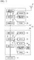
FIG 2 is a block diagram illustrating a main part of the wireless device in the embodiment of the present invention. Hereinafter, internal configurations of theinterface module 20 and thewireless module 30 included in thewireless device 12 will be described in order, with reference toFIG. 2 . Theinterface module 20 is equipped with a sensor I/F (interface) 21, acontroller 22, acommunicator 23, adiagnoser 24, adisplay 25, asetter 26, apower source controller 27, astorage 28, and apower source 29. Theinterface module 20 of the configuration is disposed between thewireless module 30 and thefield device 11. Theinterface module 20 is an interface for connecting thewireless module 30 and thefield device 11. - The sensor I/
F 21 is connected to thefield device 11. The sensor I/F 21 receives signals from thefield device 11 under control of thecontroller 22. Moreover, the sensor I/F 21 transmits signals toward thefield device 11 under control of thecontroller 22. That is, the same communication protocol as thefield device 11 is implemented in the sensor I/F 21 in order to communicate with thefield device 11. - The
controller 22 totally controls operation of theinterface module 20. For example, thecontroller 22 controls the sensor I/F 21 based on a control signal (control signal from the monitoring control device 16) included in a message transmitted from thewireless module 30 in order to obtain the measurement data (flow quantity value) measured by thefield device 11. Thecontroller 22 also controls thecommunicator 23 to transmit messages to thewireless module 30 and receive messages from thewireless module 30. For example, thecontroller 22 controls to transmit the measurement data obtained by the sensor I/F 21 to thewireless module 30. Although details will be described later, the message transmitted and received between theinterface module 20 and thewireless module 30 is a message of a predetermined format. - The
communicator 23 receives a message transmitted from thewireless module 30. Moreover, thecommunicator 23 transmits a message to thewireless module 30. Here, in a case that thecommunicator 23 receives a message from thewireless module 30, thecommunicator 23 performs predetermined message processing (reception message processing) to the received message. On the other hand, in a case that data which is to be transmitted to thewireless module 30 is output from thecontroller 22, thecommunicator 23 performs predetermined message processing (transmission message processing) to the data. Details of the reception message processing and the transmission message processing will be described later. - The
diagnoser 24 has a self-diagnostic function, and diagnoses a state of the self-module (interface module 20) under control of thecontroller 22. For example, thediagnoser 24 diagnoses an existence of failure of theinterface module 20, a connection state of thefield device 11, a remaining quantity of thepower source 29, and so on. For example, thedisplay 25 is equipped with a display device, such as a liquid crystal display. Thedisplay 25 displays various types of information under control of thecontroller 22. For example, thedisplay 25 displays measurement data (flow quantity value) obtained from thefield device 11 and information which represents a state of theinterface module 20 or thewireless module 30. - The
setter 26 is equipped with an external interface (for example, infrared communicator) connected to an external device. Thesetter 26 sets information which is to be set to thewireless device 12 based on instructions from the external device. Here, for example, the external device is a provisioning device. Thesetter 26 sets provisioning information (information which is necessary to join the wireless network N1) transmitted from the provisioning device by infrared communication. - The
power source controller 27 is equipped with a power source circuit (not shown) which converts the electric power from thepower source 29 into electric power suitable for thefield device 11, theinterface module 20, and thewireless module 30. Thepower source controller 27 supplies electric power to thefield device 11, each part of theinterface module 20, and thewireless module 30 under control of thecontroller 22. In a case that thefield device 11 incorporates a power source or receives electric power supplied from another route, thepower source controller 27 does not supply electric power to thefield device 11. Thestorage 28 stores identification information for identifying theinterface module 20 and information which represents the remaining quantity of thepower source 29. For example, thestorage 28 is a nonvolatile memory, such as a flash ROM (Read Only Memory) and EEPROM (Electrically Erasable and Programmable ROM). - The
power source 29 supplies electric power as an electric power source for operating thefield device 11, theinterface module 20, and thewireless module 30. Here, as thepower source 29, a battery (for example, a primary battery or a secondary battery of which self-discharge is very little, such as a thionyl chloride lithium battery), a fuel cell, a capacitor, or a power generation circuit which performs environmental power generation (so called, energy harvest such as a solar cell) can be used. - The
wireless module 30 is equipped with acommunicator 31, acontroller 32, awireless communicator 33, adiagnoser 34, apower source controller 35, astorage 36, and an antenna AT. Thewireless module 30 of the configuration is connected to theinterface module 20. Thewireless module 30 transmits and receives wireless signals through thewireless network N 1. - The
communicator 31 receives a message transmitted from theinterface module 20. Moreover, thecommunicator 31 transmits a message to theinterface module 20. Here, thecommunicator 31 performs the same processing as thecommunicator 23 of theinterface module 20. That is, in a case that thecommunicator 31 receives a message from theinterface module 20, thecommunicator 31 performs predetermined reception message processing (details will be described later) to the received message. On the other hand, in a case that data which is to be transmitted to theinterface module 20 is output from thecontroller 32, thecommunicator 31 performs predetermined transmission message processing (details will be described later) to the data. - The
controller 32 totally controls operation of thewireless module 30. For example, thecontroller 32 controls each part of thewireless module 30 based on data (for example, control data for controlling the wireless module 30) included in a message from theinterface module 20. Thecontroller 32 controls thecommunicator 31 to transmit a message to theinterface module 20 and receive a message from theinterface module 20. - The
wireless communicator 33 transmits wireless signals to the wireless network N1 through the antenna AT under control of thecontroller 32. Moreover, thewireless communicator 33 receives wireless signals transmitted through thewireless network N 1 and the antenna AT under control of thecontroller 32. Thewireless communicator 33 performs wireless communications in conformity with ISA100.11a described above. In addition, the antenna AT may be an internal antenna stored in thewireless module 30, or may be an external antenna disposed outside thewireless module 30. Thediagnoser 34 has a self-diagnostic function. Thediagnoser 34 diagnoses a state of the self-module (wireless module 30) under control of thecontroller 32. For example, thediagnoser 34 diagnoses an existence of failure of thewireless module 30. - The
power source controller 35 controls whether to supply electric power from theinterface module 20 to each part of thewireless module 30 or not, under control of thecontroller 32. Thepower source controller 35 performs such control in order to suppress power consumption of thepower source 29 disposed in theinterface module 20. Thestorage 36 stores information set to thewireless module 30. Thestorage 36 is the same type nonvolatile memory as thestorage 28 disposed in theinterface module 20. - Next, a format of messages transmitted and received between the
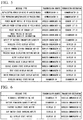
interface module 20 and thewireless module 30 which are included in thewireless device 12 is described.FIG. 3 is a drawing illustrating a format of messages transmitted and received by the wireless device in the embodiment of the present invention. Here, as shown inFIG. 3 , messages transmitted and received between theinterface module 20 and thewireless module 30 of thewireless device 12 include a data message M0, an ACK message M11, and a NACK message M12. - The data message M0 is a message for transmitting and receiving data between the
interface module 20 and thewireless module 30. The data message M0 includes eight fields in which "STX", "MID", "S/D", "M/H", "D/S", "DATA", "CRC", and "ETX" are stored respectively. On the other hand, the ACK message M11 is a message for transmitting normal reception (acknowledgment) from a receiving side module to a transmitting side module. The ACK message M11 includes six fields in which two fields where "D/S" and "DATA" are stored are omitted from the data message M0. The NACK message M12 is a message for transmitting abnormal reception (negative response) from a receiving side module to a transmitting side module. The NACK message M12 includes seven fields in which a field where "ErrCode" is stored is added, instead of the fields where "D/S" and "DATA" of the data message M0 are stored. - In addition, meaning of "STX", "MID", "S/D", "M/H", "D/S", "DATA", "CRC", "ETX", and "ErrCode" shown in
FIG. 3 is as follows. - "STX": Information which represents start of a message
- "MID": Identifier given to each message (message ID)
- "S/D": Information which represents a transmission source and a transmission destination of a message
- "M/H": Information which represents a type of "DATA" or ACK/NACK (type information)
- "D/S": Information which represents a size of "DATA"
- "DATA": Data which is to be transmitted to another module
- "CRC": Information used for error checking of transmission and reception (Cyclic Redundancy Check)
- "ETX": Information which represents end of a message
- "ErrCode": Error code
- At a time of transmitting a message, the three fields (fields where "STX", "MID", and "S/D" are stored) of the head of the data message M0, the ACK message M11, and the NACK message M12 and the two fields (field where "CRC" and "ETX" are stored) of the end thereof are added in the transmission message processing performed by the
communicator 23 of theinterface module 20 or thecommunicator 31 of thewireless module 30. These fields are deleted in the reception message processing performed by thecommunicator 23 of theinterface module 20 or thecommunicator 31 of thewireless module 30 at the time of receiving a message. - A sequence (message processing sequence) of transmitting and receiving a message described above between the
interface module 20 and thewireless module 30 includes sequences shown in the following (1) to (3). - (1) Request/response type sequence
- (2) First request type sequence
- (3) Second request type sequence
- The request/response type sequence shown in the above (1) is a sequence in which a response of one of the
interface module 20 and thewireless module 30, with respect to a request transmitted from the other one of theinterface module 20 and thewireless module 30, is transmitted. On the other hand, the first request type sequence shown in the above (2) is a sequence in which a request is transmitted from thewireless module 30 to theinterface module 20, but a response is not transmitted from theinterface module 20. On the other hand, the second request type sequence shown in the above (3) is a sequence in which a request is transmitted from theinterface module 20 to thewireless module 30, but a response is not transmitted from thewireless module 30. -
FIG. 4 is a drawing illustrating an example of messages transmitted and received by the request/response type sequence in the embodiment of the present invention. In the example shown inFIG 4 , the message of which message type ("M/H" inFIG 3 ) is "field device control request" is a message for requesting a control of thefield device 11. The transmission source of the message is thewireless communicator 33 of thewireless module 30, and the transmission destination of the message is the sensor I/F 21 of theinterface module 20. For example, the field device control request includes reading of a flow quantity value measured by thefield device 11, operating a degree of opening a valve which is thefield device 11, adjusting thefield device 11, and so on. The message of which message type is "field device control response" is a message for responding to the "field device control request". The transmission source of the message is the sensor I/F 21 of theinterface module 20, and the transmission destination of the message is thewireless communicator 33 of thewireless module 30. - Moreover, the message of which message type is "setting request" is a message for requiring a setup of information (for example, provisioning information) which is to be set to the
wireless module 30. The transmission source of the message is thesetter 26 of theinterface module 20, and the transmission destination of the message is thewireless communicator 33 of the wireless module. The message of which message type is "setting response" is a message for responding to the "setting request". The transmission source of the message is thewireless communicator 33 of thewireless module 30, and the transmission destination of the message is thesetter 26 of theinterface module 20. - In addition, the message of which message type is "firmware identifier obtaining request" is a message for requesting to obtain an identifier of the firmware used by the
interface module 20. The message of which message type is "firmware identifier obtaining response" is a message representing a response to the "firmware identifier obtaining request". According to the message, for example, if the identifier of the firmware, which is attached in accordance with the type of the diagnostic function performed by thediagnoser 24, is checked, the type of the diagnostic function performed by theinterface module 20 can be checked. The message of which message type is "storage read/write request" is a message for requesting to read and write data with respect to thestorage 28 of theinterface module 20. The message of which message types are "storage read/write response" is a message representing a response thereof. - Moreover, the message of which message type is a "sensor I/F firmware updating request" is a message for requesting to update the firmware used by the sensor I/
F 21 of theinterface module 20. The message of which message type is "sensor I/F firmware updating response" is a message representing a response thereof. By the message, for example, the communication protocol implemented in the sensor I/F 21 can be updated (for example, it can be updated to HART (registered trademark)), or the firmware used by the sensor I/F 21 can be updated to be in conformity with a revision number of the communication protocol. The transmission sources and the transmission destinations of these messages are shown inFIG 4 . -
FIG. 5 is a drawing illustrating an example of messages transmitted by the first request type sequence in the embodiment of the present invention. In the example shown inFIG. 5 , the message of which message type is "initialization completion notice of wireless module" is a message for notifying completion of initialization performed by thewireless module 30 to theinterface module 20. The message of which message type is "stop preparation completion notice of wireless module" is a message for notifying completion of stop preparation performed by thewireless module 30 to theinterface module 20. The transmission source of these messages is thecommunicator 31 of thewireless module 30, and the transmission destination of these messages is thecommunicator 23 of theinterface module 20. - Moreover, the message of which message type is "power on/off notice of field device" is a message for notifying (instructing) power on/off of the
field device 11 to theinterface module 20. The message of which message type is "supplied power setting notice of field device" is a message for notifying (instructing) a setup of power supply of thefield device 11 to theinterface module 20. The message of which message type is "reset notice of sensor I/F" is a message for notifying (instructing) a reset of the sensor I/F 21 to theinterface module 20. The transmission source of these messages is thewireless communicator 33 of thewireless module 30, and the transmission destination of these messages is the sensor I/F 21 of theinterface module 20. - Moreover, the message of which message type is "reset notice of battery remaining quantity information" is a message for notifying a reset of a remaining quantity information of the power source 29 (battery) to the
interface module 20. The message of which message type is "notice of battery consumption quantity" is a message for notifying an amount of electric power used in thewireless module 30 to theinterface module 20. The transmission source of these messages is thewireless communicator 33 of thewireless module 30, and the transmission destination of these messages is thediagnoser 24 of theinterface module 20. - Moreover, the message of which message type is "wireless state display notice", "display common setting changing notice", "process value displaying setting notice", "alert display notice", "process value display notice", "device search state display notice", "test state display notice", or "write prohibition state display notice" is a notice (instruction) representing that the
wireless module 30 makes thedisplay 25 of theinterface module 20 display various types of information, such as measurement data (process value) of thefield device 11, a wireless state, an alert, and so on. The transmission source of these messages is thewireless communicator 33 of thewireless module 30, and the transmission destination of these messages is thedisplay 25 of theinterface module 20. - Moreover, the message of which message type is "wireless module state notice" is a message for notifying a state of the
wireless module 30 to theinterface module 20. The transmission source of the message is thediagnoser 34 of thewireless module 30, and the transmission destination of the message is thediagnoser 24 of theinterface module 20. -
FIG. 6 is a drawing illustrating an example of messages transmitted by the second request type sequence in the embodiment of the present invention. In the example shown inFIG. 6 , the message of which message type is "diagnosis information notice" is a message for notifying diagnosis information, which is a result of a diagnosis of theinterface module 20, to thewireless module 30. The message of which message type is "battery remaining quantity notice" is a message for notifying a battery remaining quantity of thepower source 29 to thewireless module 30. The transmission source of these messages is thediagnoser 24 of theinterface module 20, and the transmission destination of these messages is thewireless communicator 33 of thewireless module 30. - Moreover, the message of which message type is "factory shipment state notice", "dip switch state changing notice", or "all display state notice" is a message for notifying various states of each part of the
interface module 20, which can be displayed on thedisplay 25, to thewireless module 30. The transmission source of these messages is thedisplay 25 of theinterface module 20, and the transmission destination of these messages is thewireless communicator 33 of thewireless module 30. - Next, an operation of the
wireless device 12 will be described. As described above, the message processing sequences between theinterface module 20 and thewireless module 30, which are disposed in thewireless device 12, include (1) request/response type sequence, (2) first request type sequence, and (3) second request type sequence. For this reason, operations in a case that these message processing sequences are performed will be described below in order. -
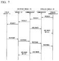
FIG. 7 is a timing chart illustrating an example of operation of thewireless device 12 in a case that the request/response type sequence is performed in the embodiment of the present invention. The timing chart shown inFIG. 7 shows an operation in a case that thewireless device 12 obtains measurement data of thefield device 11. This operation is started when thewireless communicator 33 of thewireless module 30 receives a control signal (control signal for instructing to obtain measurement data) transmitted from themonitoring control device 16 through thewireless network N 1. - When the operation is started, first, the control signal received by the
wireless communicator 33 of thewireless module 30 is output to thecontroller 32. Then, thecontroller 32 generates data which includes the third field to the sixth field from the head of the data message M0 shown inFIG 3 . Specifically, the data in which the following information was stored in the third field to the sixth field from the head of the data message M0 is generated. - The third "S/D": information of which transmission source is the
wireless communicator 33 and of which transmission destination is the sensor I/F 21 - The fourth "M/H": message type which is "field device control request"
- The fifth "D/S": information which represents the size of the data stored in the sixth field
- The sixth "DATA": control signal from the
monitoring control device 16 - When the above data is generated by the
controller 32, the generated data is output from thecontroller 32 to thecommunicator 31. When the data is output from thecontroller 32 to thecommunicator 31, as shown inFIG. 7 , a request (field device control request) of which transmission source is thewireless communicator 33 is transmitted to thecommunicator 31. If the data from thecontroller 32 is input, thecommunicator 31 performs the above-described transmission message processing. -
FIG. 8 is a flow chart illustrating the transmission message processing performed by the wireless device by the embodiment of the present invention. For example, the program for performing the flow chart may be stored in thestorage 36, or may be stored in another storage medium. For example, the flow chart shown inFIG. 8 is performed every time data is output from thecontroller 32 to thecommunicator 31. Thecommunicator 31 performs processing shown in the flow chart shown inFIG. 8 . When the transmission message processing is started, first, thecommunicator 31 adds the "MID" (message ID: refer toFIG. 3 ) to the head of the data from the controller 32 (Step S11). Next, thecommunicator 31 performs a special character processing (Step S12). If a special character used as "STX" or "ETX", which is information representing start or end of the message, is included in the data from thecontroller 32, the special character is replaced to another character in the special character processing. - Next, the
communicator 31 adds "STX" to the head of the data (Step S13). Subsequently, thecommunicator 31 calculates CRC information by using the data before the above "STX" is added, and adds "CRC" to the end of the data to which the processing of Step S13 was performed (data in which "STX" was added to the head) (Step S14). Subsequently, thecommunicator 31 adds "ETX" to the end of the data to which the processing ofStep S 14 was performed (data in which "CRC" was added to the end) (Step S15). By the above-described processing, a message in which the message type "field device control request" has been stored in the fourth field "M/H" and the control signal from themonitoring control device 16 has been stored in the sixth field "DATA" (message of the same format as the data message M0 shown inFIG. 3 ) is generated. - After the above-described processing is completed, the
communicator 31 transmits the generated message to thecommunicator 23 of the interface module 20 (Step S16). Thereby, as shown inFIG. 7 , a request of which transmission source is thewireless communicator 33 is transmitted from thecommunicator 31 to the communicator 23 (transmitting step). If the message is transmitted, thecommunicator 31 determines whether a transmission error exists or not (Step S 17). Specifically, thecommunicator 31 determines whether an error, such as an error in a physical layer and an error of retransmission, exists or not. - If it is determined that a transmission error does not exist (if the determination result is "NO"), the
communicator 31 ends the series of the transmission message processing shown inFIG. 8 . On the other hand, if it is determined that a transmission error exists (if the determination result is "YES"), thecommunicator 31 performs error processing (Step S18). Specifically, thecommunicator 31 interrupts the transmission processing and returns to an initial state (state before the processing of Step S11 is performed). - In addition, if the message from the
communicator 31 is received by thecommunicator 23, as shown inFIG. 7 , in a case of normal reception, an ACK message M11 (refer toFIG. 3 ) is transmitted from thecommunicator 23 to thecommunicator 31. On the other hand, in a case of abnormal reception, a NACK message M12 (refer toFIG. 3 ) is transmitted from thecommunicator 23 to thecommunicator 31. If the ACK message M11 or the NACK message M12 is received by thecommunicator 31, thewireless communicator 33 is notified thereof. - If the message from the
communicator 31 is received normally, thecommunicator 23 performs the above-described reception message processing.FIG 9 is a flow chart illustrating the reception message processing performed by the wireless device in the embodiment of the present invention. For example, the program for performing this flow chart may be stored in thestorage 28, or may be stored in another storage medium. For example, the flow chart shown inFIG 9 is performed every time a message from thecommunicator 31 is received. - When the reception message processing is started, first, the
communicator 23 determines whether a reception error exists or not (Step S21). Specifically, thecommunicator 23 determines whether an error, such as an error in a physical layer (for example, a framing error), timeout between characters, and frame reception timeout, exists or not. If it is determined that a reception error does not exist (if the determination result is "NO"), thecommunicator 23 deletes "STX" added to the head of the received message (Step S22). Subsequently, thecommunicator 23 deletes "ETX" added to the end of the received message (Step S23). - Next, the
communicator 23 determines whether a CRC error exists or not (Step S24). Specifically, thecommunicator 23 calculates CRC information by using the data stored in the second field to the sixth field from the head of the received message (refer to data message M0 shown inFIG 3 ). Thecommunicator 23 compares the calculated CRC information and the CRC information stored in the seventh field of the received message. - If it is determined that the CRC error does not exist (if the determination result of Step S24 is "NO"), the
communicator 23 performs a special character processing (Step S25). Here, the special character processing is processing for restoring, to the original special character, the character replaced by the special character processing in the transmission message processing described by usingFIG. 8 . Subsequently, thecommunicator 23 stores the "MID" (message ID) added to the received message (Step S26). - In addition, in the processing of Step S26, processing in a case of receiving a request is different from processing in a case of receiving a response. Here, since it is a case that the request from the
wireless module 30 is received, thecommunicator 23 stores the message ID as described above. On the other hand, if thecommunicator 23 receives a response, thecommunicator 23 checks the message ID added to the message of the response and the message ID previously stored when transmitting the request. If thecommunicator 23 receives the request, thecommunicator 23 omits the processing of Step S27 (determination processing of check error). On the other hand, if thecommunicator 23 receives the response, thecommunicator 23 performs the processing of Step S27. - When the above-described processing ends, processing of transmitting the data obtained by the processing (data which includes the third field to the sixth field from the head of the data message M0 in
FIG. 3 ) is performed (Step S28). If it is determined that a reception error exists at Step S21, if it is determined that a CRC error exists at Step S24, or if it is determined that a check error exists at Step S27 (if at least one of the determination result of Steps S21, S24, and S27 is "YES"), thecommunicator 23 performs an error processing (Step S29). Specifically, thecommunicator 23 interrupts the processing and returns to an initial state (state before the processing of Step S21 is performed). -
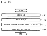
FIG. 10 is a flow chart illustrating details of the data transfer processing performed at Step S28 shown inFIG. 9 . For example, the program for performing this flow chart may be stored in thestorage 28, or may be stored in another storage medium. The flow chart shown inFIG. 10 is performed every time the data processed by thecommunicator 23 is input into thecontroller 22. When the data transfer processing is started, first, thecontroller 22 stores the "S/D" which is included in the data from the communicator 23 (Step S31). This processing is performed in preparation for a response to a request from thewireless module 30. - Next, the
controller 22 analyzes the "M/H" included in the data from thecommunicator 23, and determines a type of the data included in the message from the wireless module 30 (Step S32). Subsequently, thecontroller 22 performs processing according to the result of the analysis of Step S32 (Step S33). Here, since the message type "field device control request" is stored in the message from thewireless module 30, thecontroller 22 transmits the data from thecommunicator 23 to the sensor I/F 21 (refer toFIG. 4 ). Thereby, as shown inFIG 7 , the request (field device control request) of which transmission source is thewireless communicator 33 is transmitted to the sensor I/F 21. - As shown in
FIG. 7 , the request transmitted to the sensor I/F 21 is transmitted to thefield device 11. As a response to the request, measurement data is transmitted from thefield device 11 to the sensor I/F 21. The measurement data (response) received by the sensor I/F 21 is input into thecontroller 22. - Then, the
controller 22 generates data which includes the third field to the sixth field from the head of the data message M0 inFIG 3 (Step S34). Specifically, thecontroller 22 generates the data in which the following information is stored in the third field to the sixth field from the head of the data message M0. The information stored in the third field shown below is information in which the transmission source and the transmission destination of the "S/D", which is stored at the processing of Step S31 inFIG. 10 in preparation for the response to the request from thewireless module 30, are exchanged. - The third "S/D": information of which transmission source is the sensor I/
F 21 and of which transmission destination is thewireless communicator 33 - The fourth "M/H": message type which is "field device control response"
- The fifth "D/S": information which represents the size of the data stored in the sixth field
- The sixth "DATA": measurement data from the
field device 11 - When the above data is generated, the
controller 22 outputs the generated data to thecommunicator 23. When the data is output from thecontroller 22 to thecommunicator 23, as shown inFIG. 7 , a response (field device control response) of which transmission source is the sensor I/F 21 is transmitted to thecommunicator 23. If the data from thecontroller 22 is input, thecommunicator 23 performs the same processing as the transmission message processing described by usingFIG 8 , and the message which is to be replied to thewireless module 30 is generated. Thereby, the message of the same format as the message, which was transmitted from thewireless module 30 and received by thecommunicator 23, is generated. - After the above-described processing is completed, the
communicator 23 transmits the generated message to thecommunicator 31 of the wireless module 30 (Reply Step). Thereby, as shown inFIG. 7 , a response of which transmission source is the sensor I/F 21 is transmitted from thecommunicator 23 to thecommunicator 31. If thecommunicator 31 receives the message from thecommunicator 23, thecommunicator 31 performs the same processing as the reception message processing described by usingFIG. 9 . The message processing performed here is reception message processing with respect to the response. For this reason, thecommunicator 31 performs check processing (Step S26), and determines whether a check error exists or not (Step S27). - In addition, if the message from the
communicator 23 is received by thecommunicator 31, as shown inFIG. 7 , in a case of normal reception, an ACK message M11 (refer toFIG. 3 ) is transmitted from thecommunicator 31 to thecommunicator 23. On the other hand, in a case of abnormal reception, a NACK message M12 (refer toFIG. 3 ) is transmitted from thecommunicator 31 to thecommunicator 23. If the ACK message M11 or the NACK message M12 is received by thecommunicator 23, the sensor I/F 21 is notified thereof. - The data obtained by the reception message processing is output from the
communicator 31 to thecontroller 32. Here, since the message type "field device control response" is stored in the data input from thecommunicator 31 into thecontroller 32, thecontroller 32 transmits the data from thecommunicator 31 to the wireless communicator 33 (refer toFIG. 4 ). Thereby, as shown inFIG 7 , the response received by thecommunicator 31 is transmitted to thewireless communicator 33. - The data (data includes measurement data of the field device 11) transmitted to the
wireless communicator 33 is transmitted toward themonitoring control device 16 through the wireless network N1. Thus, the measurement data of thefield device 11 is collected by themonitoring control device 16 based on the control signal from themonitoring control device 16. - In addition, in the example described above, the
wireless module 30 transmits a request to theinterface module 20, and theinterface module 20 transmits a response to thewireless module 30. Contrary to this example, in a case that theinterface module 20 transmits a request to thewireless module 30, and thewireless module 30 transmits a response to theinterface module 20, the same operation as the operation described above is performed. - Moreover, in the example described above, a message including a control request with respect to the
field device 11 or a control response from thefield device 11 as a message type is transmitted and received between thewireless module 30 and theinterface module 20. In a case that a message including a processing request with respect to theinterface module 20 and a processing response from theinterface module 20 as a message type is transmitted and received, or a message including a processing request with respect to thewireless module 30 and a processing response from thewireless module 30 as a message type is transmitted and received, the same operation as the operation described above is performed. - Here, in a case that a message type included in the received message is a processing request, the
interface module 20 and thewireless module 30 set a message type included in a message, which is to be replied, to a processing response. Moreover, in a case that a message type included in the received message is a processing request with respect to the self-module, theinterface module 20 and thewireless module 30 store, in the message which is to be replied, a processing result of the processing performed according to the processing request. -
FIG. 11 is a timing chart illustrating an example of operation of thewireless device 12 in a case that the first request type sequence is performed in the embodiment of the present invention. For example, the timing chart shown inFIG. 11 shows an operation in a case that thewireless module 30 performs a display notice (here, "wireless state display notice") to theinterface module 20. - When an operation is started, first, information representing a wireless state, which is to be notified, is output from the
wireless communicator 33 to thecontroller 32. Then, thecontroller 32 generates data which includes the third field to the sixth field from the head of the data message M0 inFIG. 3 . Specifically, the data in which the following information is stored in the third field to the sixth field from the head of the data message M0 is generated. - The third "S/D": information of which transmission source is the
wireless communicator 33 and of which transmission destination is thedisplay 25 - The fourth "M/H": message type which is "wireless state display notice"
- The fifth "D/S": information which represents the size of the data stored in the sixth field
- The sixth "DATA": information which represents a wireless state
- When the above data is generated by the
controller 32, the generated data is output from thecontroller 32 to thecommunicator 31. Thereby, as shown inFIG. 11 , a request (wireless state display notice), of which transmission source is thewireless communicator 33, is transmitted to thecommunicator 31. If the data from thecontroller 32 is input, thecommunicator 31 performs the same processing as the transmission message processing described by usingFIG 8 , and the message which is to be transmitted to theinterface module 20 is generated. - After the above-described processing is completed, processing of transmitting the generated message to the
communicator 23 of theinterface module 20 is performed. Thereby, as shown inFIG. 11 , a request of which transmission source is thewireless communicator 33 is transmitted from thecommunicator 31 to thecommunicator 23. When the message from thecommunicator 31 is received, thecommunicator 23 performs the same processing as the reception message processing described by usingFIG. 9 . - In addition, if the message from the
communicator 31 is received by thecommunicator 23, as shown inFIG 11 , in a case of normal reception, an ACK message M11 (refer toFIG 3 ) is transmitted from thecommunicator 23 to thecommunicator 31, and in a case of abnormal reception, a NACK message M12 (refer toFIG. 3 ) is transmitted from thecommunicator 23 to thecommunicator 31. If the ACK message M11 or the NACK message M12 is received by thecommunicator 31, thewireless communicator 33 is notified thereof. - The data obtained by the reception message processing is output from the
communicator 23 to thecontroller 22. Here, since the message type "wireless state display notice" is stored in the data input from thecommunicator 23 into thecontroller 22, thecontroller 22 transmits the data from thecommunicator 23 to the display 25 (refer toFIG. 5 ). Thereby, as shown inFIG. 11 , the request received by thecommunicator 23 is transmitted to thedisplay 25. Thus, the information which represents a wireless state of thewireless module 30 is displayed on thedisplay 25 of theinterface module 20. As shown inFIG. 11 , in the first request type sequence, theinterface module 20 which received the request from thewireless module 30 does not reply a response to thewireless module 30. -
FIG 12 is a timing chart illustrating an example of operation of thewireless device 12 in a case that the second request type sequence is performed in the embodiment of the present invention. For example, the timing chart shown inFIG. 12 shows an operation in a case that theinterface module 20 performs a battery remaining quantity notice to thewireless module 30. - When an operation is started, first, information representing battery power, which is to be notified, is output from the
diagnoser 24 to thecontroller 22. Then, thecontroller 22 generates data which includes the third field to the sixth field from the head of the data message M0 inFIG 3 . Specifically, the data in which the following information is stored in the third field to the sixth field from the head of the data message M0 is generated. - The third "S/D": information of which transmission source is the
diagnoser 24 and of which transmission destination is thewireless communicator 33 - The fourth "M/H": message type which is "battery remaining quantity notice"
- The fifth "D/S": information which represents the size of the data stored in the sixth field
- The sixth "DATA": information which represents battery remaining quantity
- When the above data is generated by the
controller 22, thecontroller 22 outputs the generated data to thecommunicator 23. Thereby, as shown inFIG. 12 , the request (battery remaining quantity notice), of which transmission source is thediagnoser 24, is transmitted to thecommunicator 23. If the data from thecontroller 22 is input, thecommunicator 23 performs the same processing as the transmission message processing described by usingFIG. 8 , and the message which is to be transmitted towireless module 30 is generated. - After the above-described processing is completed, processing of transmitting the generated message to the
communicator 31 of thewireless module 30 is performed. Thereby, as shown inFIG 12 , a request of which transmission source is thediagnoser 24 is transmitted from thecommunicator 23 to thecommunicator 31. When the message from thecommunicator 23 is received, thecommunicator 31 performs the same processing as the reception message processing described by usingFIG. 9 . - In addition, if the message from the
communicator 23 is received by thecommunicator 31, as shown inFIG. 12 , in a case of normal reception, an ACK message M11 (refer toFIG. 3 ) is transmitted from thecommunicator 31 to thecommunicator 23. On the other hand, in a case of abnormal reception, a NACK message M12 (refer toFIG. 3 ) is transmitted from thecommunicator 31 to thecommunicator 23. If the ACK message M11 or the NACK message M12 is received by thecommunicator 23, thediagnoser 24 is notified thereof. - The data obtained by reception message processing is output from the
communicator 31 to thecontroller 32. Here, since the message type "battery remaining quantity notice" is stored in the data input from thecommunicator 31 into thecontroller 32, thecontroller 32 transmits the data from thecommunicator 31 to the wireless communicator 33 (refer toFIG. 6 ). Thereby, as shown inFIG. 12 , the request received by thecommunicator 31 is transmitted to thewireless communicator 33. Thus, the information which represents the remaining quantity of the power source 29 (battery) of theinterface module 20 is transmitted to thewireless module 30. As shown inFIG. 12 , in the second request type sequence, thewireless module 30 which received the request from theinterface module 20 does not reply a response to theinterface module 20. - As described above, in the present embodiment, the
wireless module 30 generates a message of a predetermined format including data which is to be transmitted to theinterface module 20 and a message type, and thewireless module 30 transmits it to theinterface module 20. Theinterface module 20 generates a message in accordance with the message type included in the received message, and replies it to thewireless module 30. The generated message includes data which is to be replied to thewireless module 30 and the message type, and the generated message is the same in a format as the received message. - On the contrary, the
interface module 20 generates a message of a predetermined format including data which is to be transmitted to thewireless module 30 and a message type, and theinterface module 20 transmits it to thewireless module 30. Thewireless module 30 generates a message in accordance with the message type included in the received message, and replies it to theinterface module 20. The generated message includes data which is to be replied to theinterface module 20 and the message type, and the generated message is the same in a format as the received message. In addition, in the present embodiment, notifications and instructions from thewireless module 30 to theinterface module 20, and notifications and instructions from theinterface module 20 to thewireless module 30 are performed by using the same message in a format as the above-described message. - Thus, in the present embodiment, the message of the format unified between the
interface module 20 and thewireless module 30 is transmitted and received. For this reason, design and development of theinterface module 20 and thewireless module 30 can be performed easily. Thereby, even if theinterface module 20 and thewireless module 30 are developed and manufactured by manufacturers which differ from each other, thefield device 11 can be operated as a wireless field device which performs stable wireless communications. -
FIG. 13 is a drawing illustrating an application example of a wireless communication system in which the wireless device in the embodiment of the present invention is used. InFIG. 13 , parts that correspond to those inFIG. 1 are assigned the same reference numerals. Thewireless communication system 2 shown inFIG. 13 is a communication system which can makefield devices - Although the
field devices field device 11 shown inFIG. 1 , different communication protocols are implemented in thefield device field device 11 a. On the other hand, a communication protocol in conformity with MODBUS (registered trademark) is implemented in thefield device 11b. - The
interface modules interface module 20 shown inFIG 1 . A communication protocol which can communicate with thefield device 11 a is implemented in theinterface module 20a. Moreover, a communication protocol which can communicate with thefield device 11b is implemented in theinterface module 20b. For example, a communication protocol in conformity with HART (registered trademark) is implemented in theinterface module 20a, and a communication protocol in conformity with MODBUS (registered trademark) is implemented in theinterface module 20b. - Although the
monitoring control device 17 is the same as themonitoring control device 16 shown inFIG. 1 , themonitoring control device 17 can communicate with both thefield devices monitoring control device 17 can transmit a control signal specified by HART (registered trademark) and a control signal specified by MODBUS (registered trademark). - In the
wireless communication system 2, thewireless device 12 is connected to thefield devices various field devices field devices field devices - As described above, although a wireless device, a wireless communication system, a wireless module, an interface module, and a communication method according to embodiments of the present invention have been described above, the present invention is not restricted to the above-described embodiments, and can be freely modified within the scope thereof. For example, although the foregoing descriptions of the embodiments have been examples in which the wireless device performs wireless communications in conformity with ISA100.11a, the present invention can be also applied to a wireless device which perform wireless communications in conformity with WirelessHART (registered trademark).
-
- 11
- Field device
- 11a
- Field device
- 11b
- Field device
- 12
- Wireless device
- 20
- Interface Module
- 20a
- Interface module
- 20b
- Interface module
- 22
- Controller
- 23
- Communicator
- 30
- Wireless module
- 31
- Communicator
- 32
- Controller
Claims (20)
- A wireless device comprising:a wireless module configured to wirelessly transmit a signal which has been received from a field device, and wirelessly receive a signal which is to be transmitted to the field device; andan interface module which is disposed between the wireless module and the field device,wherein one of the wireless module and the interface module generates a first message having a predetermined format, the first message includes data and type information, the data is to be transmitted to other one of the wireless module and the interface module, the type information represents a type of the data, and the one of the wireless module and the interface module transmits the first message to the other one of the wireless module and the interface module, andwherein the other one of the wireless module and the interface module generates a second message having the same format as the first message in accordance with the type information included in the first message, the second message includes data and type information, the data is to be replied to the one of the wireless module and the interface module, the type information represents a type of the data, and the other one of the wireless module and the interface module replies the second message to the one of the wireless module and the interface module.
- The wireless device according to claim 1,
wherein in a case that the type information included in the first message is a processing request, the other one of the wireless module and the interface module stores the type information in the second message as a processing response. - The wireless device according to claim 2,
wherein in a case that the type information included in the first message is a processing request to a self-module, the other one of the wireless module and the interface module stores, in the second message, a processing result of processing performed according to the processing request as data which is to be replied. - The wireless device according to claim 2,
wherein the processing request, as the type information included in the first message which is transmitted from the wireless module to the interface module, includes a control request to the field device, and
wherein the processing response, as the type information included in the second message which is replied from the interface module to the wireless module, includes a control response from the field device. - The wireless device according to any one of claims 1 to 3,
wherein in a case that the type information included in the first message represents notifications or instructions, the other one of the wireless module and the interface module performs processing in accordance with the notifications or the instructions, and does not reply to the one of the wireless module and the interface module. - The wireless device according to claim 5,
wherein the interface module comprises a display,
wherein the processing request, as the type information included in the first message which is transmitted from the wireless module to the interface module, includes a wireless state display notice for displaying information representing a wireless state of the wireless module on the display, and
wherein even if the interface module receives the first message about the wireless state display notice, the interface module does not reply the second message to the wireless module. - The wireless device according to claim 5,
wherein the interface module comprises a power source,
wherein the processing request, as the type information included in the first message which is transmitted from the interface module to the wireless module, includes a battery remaining quantity notice for notifying a battery remaining quantity, and
wherein even if the wireless module receives the first message about the battery remaining quantity notice, the wireless module does not reply the second message to the interface module. - The wireless device according to claim 1,
wherein the wireless module comprises:a wireless communicator configured to wirelessly communicate;a first communicator configured to communicate with the interface module; anda first controller configured to control the wireless communicator and the first communicator. - The wireless device according to claim 8,
wherein the first controller generates data which includes information representing a transmission source and a transmission destination of the first message, the type information, information representing a size of data which is to be transmitted to the interface module, and data which is to be transmitted to the interface module. - The wireless device according to claim 9,
wherein the first communicator adds, to the data generated by the first controller, information representing a start of the first message, ID of the first message, information which is used for performing error check of transmission and reception, and information representing an end of the first message, to generate the first message, and
wherein the first communicator transmits the generated first message to the interface module. - The wireless device according to claim 10,
wherein the interface module comprises:a sensor I/F configured to communicate with the field device;a second communicator configured to communicate with the wireless module; anda second controller configured to control the sensor I/F and the second communicator. - The wireless device according to claim 11,
wherein the second communicator deletes, from the first message received from the wireless module, the information representing the start of the first message and the information representing the end of the first message. - The wireless device according to claim 12,
wherein the second communicator determines whether an error exists or not based on the information which is used for performing the error check of transmission and reception, which is included in the first message received from the wireless module. - The wireless device according to claim 13,
wherein in a case that the second communicator determines the error does not exist, the second controller analyzes the type information included in the first message, and performs in accordance with a result of the analyze. - A wireless communication system comprising:a first wireless module configured to wirelessly transmit a signal which has been received from a first field device, and wirelessly receive a signal which is to be transmitted to the first field device;a first interface module which is disposed between the first wireless module and the first field device, a first communication protocol being implemented in the first interface module;a second wireless module configured to wirelessly transmit a signal which has been received from a second field device, and wirelessly receive a signal which is to be transmitted to the second field device; anda second interface module which is disposed between the second wireless module and the second field device, a second communication protocol being different from the first communication protocol and implemented in the second interface module;wherein one of the first wireless module and the first interface module generates a first message having a predetermined format, the first message includes data and type information, the data is to be transmitted to other one of the first wireless module and the first interface module, the type information represents a type of the data, and the one of the first wireless module and the first interface module transmits the first message to the other one of the first wireless module and the first interface module,wherein the other one of the first wireless module and the first interface module generates a second message having the same format as the first message in accordance with the type information included in the first message, the second message includes data and type information, the data is to be replied to the one of the first wireless module and the first interface module, the type information represents a type of the data, and the other one of the first wireless module and the first interface module replies the second message to the one of the first wireless module and the first interface module,wherein one of the second wireless module and the second interface module generates a third message having a predetermined format, the third message includes data and type information, the data is to be transmitted to other one of the second wireless module and the second interface module, the type information represents a type of the data, and the one of the second wireless module and the second interface module transmits the third message to the other one of the second wireless module and the second interface module, andwherein the other one of the second wireless module and the second interface module generates a fourth message having the same format as the third message in accordance with the type information included in the third message, the fourth message includes data and type information, the data is to be replied to the one of the second wireless module and the second interface module, the type information represents a type of the data, and the other one of the second wireless module and the second interface module replies the fourth message to the one of the second wireless module and the second interface module.
- A wireless module comprising:a communicator configured to wirelessly receive a first message which has been received from outside, and wirelessly transmit a second message to outside; anda controller configured to control the communicator to transmit the second message, the second message having a predetermined format, the second message including data and type information, the data is to be transmitted to outside, the type information representing a type of the data.
- The wireless module according to claim 16,
wherein the controller replies the second message from the communicator to outside in accordance with the type information included in the first message, and
wherein the second message is the same format as the first message, which includes data which is to be replied to outside and type information representing a type of the data. - An interface module comprising:a communicator configured to wirelessly receive a first message from a wireless module, and wirelessly transmit a second message to the wireless module; anda controller configured to control the communicator to reply the second message from the communicator to the wireless module in accordance with type information included in the first message, the second message having the same format as the first message, the second message including data and type information, the data is to be replied to the wireless module, the type information representing a type of the data.
- The interface module according to claim 18,
wherein the controller transmits a third message from the communicator to the wireless module, and
wherein the third message is of a predetermined format which includes data which is to be transmitted to the wireless device and type information representing a type of the data. - A communication method between a wireless module which transmits and receives signals wirelessly and an interface module which is disposed between the wireless module and the field device, comprising:generating, by one of the wireless module and the interface module, first message having a predetermined format, the first message including data and type information, the data being to be transmitted to other one of the wireless module and the interface module, the type information representing a type of the data;transmitting, by the one of the wireless module and the interface module, the first message to the other one of the wireless module and the interface module;generating, by the other one of the wireless module and the interface module, a second message having the same format as the first message in accordance with the type information included in the first message, the second message including data and type information, the data being to be replied to the one of the wireless module and the interface module, the type information representing a type of the data; andreplying, by the other one of the wireless module and the interface module, the second message to the one of the wireless module and the interface module.
Applications Claiming Priority (2)
| Application Number | Priority Date | Filing Date | Title |
|---|---|---|---|
| JP2013221442A JP5971225B2 (en) | 2013-10-24 | 2013-10-24 | Wireless device, wireless module, interface module, and communication method |
| PCT/JP2014/077920 WO2015060291A1 (en) | 2013-10-24 | 2014-10-21 | Wireless device, wireless communication system, wireless module, interface module, and communication method |
Publications (3)
| Publication Number | Publication Date |
|---|---|
| EP3062178A1 true EP3062178A1 (en) | 2016-08-31 |
| EP3062178A4 EP3062178A4 (en) | 2017-07-12 |
| EP3062178B1 EP3062178B1 (en) | 2020-12-23 |
Family
ID=52992885
Family Applications (1)
| Application Number | Title | Priority Date | Filing Date |
|---|---|---|---|
| EP14855130.2A Active EP3062178B1 (en) | 2013-10-24 | 2014-10-21 | Wireless device, wireless communication system, wireless module, interface module, and communication method |
Country Status (5)
| Country | Link |
|---|---|
| US (1) | US9693174B2 (en) |
| EP (1) | EP3062178B1 (en) |
| JP (1) | JP5971225B2 (en) |
| CN (1) | CN105765469B (en) |
| WO (1) | WO2015060291A1 (en) |
Cited By (1)
| Publication number | Priority date | Publication date | Assignee | Title |
|---|---|---|---|---|
| CN114585043A (en) * | 2022-03-25 | 2022-06-03 | 电子科技大学 | Routing method, device, computer equipment and storage medium |
Families Citing this family (7)
| Publication number | Priority date | Publication date | Assignee | Title |
|---|---|---|---|---|
| DE102015109482B4 (en) | 2015-06-15 | 2018-12-13 | Phoenix Contact Gmbh & Co. Kg | FIELDBUS DEVICE FOR DETECTING A OPERATING STATE OF AN AUTOMATED ENGINEERING DEVICE |
| US10649425B2 (en) * | 2015-07-14 | 2020-05-12 | Honeywell International Inc. | Smart integral field upgrade module |
| JP6344350B2 (en) | 2015-09-18 | 2018-06-20 | 横河電機株式会社 | Control device |
| GB2612179B (en) * | 2016-05-16 | 2023-09-13 | Fisher Rosemount Systems Inc | Multi-protocol field device in process control systems |
| JP6477662B2 (en) * | 2016-10-28 | 2019-03-06 | 横河電機株式会社 | Antenna module |
| JP6843681B2 (en) * | 2017-04-07 | 2021-03-17 | 三菱電機株式会社 | Wireless communication system and wireless communication equipment |
| JP6496874B1 (en) * | 2018-08-31 | 2019-04-10 | 三菱日立パワーシステムズインダストリー株式会社 | Communications system |
Family Cites Families (13)
| Publication number | Priority date | Publication date | Assignee | Title |
|---|---|---|---|---|
| US5557634A (en) | 1994-10-14 | 1996-09-17 | International Business Machines Corporation | Multiprotocol directed infrared communication controller |
| JP2000083287A (en) * | 1998-06-30 | 2000-03-21 | Toshiba Lighting & Technology Corp | Remote control system |
| JP2000295165A (en) * | 1999-04-06 | 2000-10-20 | Nec Corp | Code division multiple access system |
| JP2004252619A (en) * | 2003-02-19 | 2004-09-09 | Hitachi Ltd | Information communication processor and computer software |
| US7460865B2 (en) * | 2003-06-18 | 2008-12-02 | Fisher-Rosemount Systems, Inc. | Self-configuring communication networks for use with process control systems |
| DE102004020393A1 (en) | 2004-04-23 | 2005-11-10 | Endress + Hauser Gmbh + Co. Kg | Radio module for field devices of automation technology |
| US8050624B2 (en) * | 2005-06-24 | 2011-11-01 | Rosemount, Inc. | Distributed process control system and method utilizing wireless communication of packet messages |
| US7848827B2 (en) * | 2006-03-31 | 2010-12-07 | Honeywell International Inc. | Apparatus, system, and method for wireless diagnostics |
| DE102006017243B4 (en) * | 2006-04-12 | 2011-09-15 | Vega Grieshaber Kg | Transceiver for wireless transmission of field device signals |
| EP2005651B1 (en) * | 2006-04-12 | 2010-09-08 | VEGA Grieshaber KG | Transceiver for wireless transmission of field device signals |
| JP2009025879A (en) * | 2007-07-17 | 2009-02-05 | Denso Wave Inc | Communication system for robot device |
| DE102008037193A1 (en) * | 2008-08-11 | 2010-02-18 | Endress + Hauser Process Solutions Ag | Method for monitoring the remaining service life of a battery |
| US9065813B2 (en) * | 2011-03-18 | 2015-06-23 | Honeywell International Inc. | Adapter device for coupling an industrial field instrument to an industrial wireless network and related system and method |
-
2013
- 2013-10-24 JP JP2013221442A patent/JP5971225B2/en active Active
-
2014
- 2014-10-21 EP EP14855130.2A patent/EP3062178B1/en active Active
- 2014-10-21 CN CN201480057597.1A patent/CN105765469B/en active Active
- 2014-10-21 WO PCT/JP2014/077920 patent/WO2015060291A1/en active Application Filing
- 2014-10-21 US US15/030,164 patent/US9693174B2/en active Active
Cited By (1)
| Publication number | Priority date | Publication date | Assignee | Title |
|---|---|---|---|---|
| CN114585043A (en) * | 2022-03-25 | 2022-06-03 | 电子科技大学 | Routing method, device, computer equipment and storage medium |
Also Published As
| Publication number | Publication date |
|---|---|
| EP3062178A4 (en) | 2017-07-12 |
| CN105765469A (en) | 2016-07-13 |
| JP2015082303A (en) | 2015-04-27 |
| WO2015060291A1 (en) | 2015-04-30 |
| EP3062178B1 (en) | 2020-12-23 |
| JP5971225B2 (en) | 2016-08-17 |
| US20160261972A1 (en) | 2016-09-08 |
| US9693174B2 (en) | 2017-06-27 |
| CN105765469B (en) | 2019-01-01 |
Similar Documents
| Publication | Publication Date | Title |
|---|---|---|
| EP3062178B1 (en) | Wireless device, wireless communication system, wireless module, interface module, and communication method | |
| CN106164790B (en) | Process variable transmitter with loop powered wireless transceiver | |
| JP2006318148A (en) | Field equipment control system | |
| CN102445928A (en) | Field device with self description | |
| CN102644798A (en) | Method and apparatus for partial stroke testing of emergency shutdown valve | |
| US9311758B2 (en) | Vehicle control device and method | |
| EP3260937A1 (en) | Device maintenance apparatus and method | |
| US20130231152A1 (en) | Master Antenna Controller Application And Device | |
| US8634482B2 (en) | High power radio device communication parameter configuration and methods using limited configuration power | |
| US10218533B2 (en) | Wireless device and interface module | |
| EP2398190B1 (en) | Field communication system | |
| US20140059252A1 (en) | Method for configuring a field device and corresponding system for parameterization | |
| JP6183131B2 (en) | Wireless module and wireless device | |
| EP3534542B1 (en) | Antenna module | |
| JP2006065385A (en) | Field equipment | |
| JP4873220B2 (en) | Field communication system | |
| US9735875B2 (en) | Field device and communication system | |
| JP2009225481A (en) | Communication apparatus, communication control method and communication control program | |
| JP2005184551A (en) | Communication apparatus, communication control method and communication control program | |
| JP2010081175A (en) | Remote supervisory controller, data terminal for maintenance therefor, and maintenance system | |
| BR112014015852B1 (en) | MODULE FOR ENABLING WIRELESS FUNCTIONALITY IN AN ELECTRONIC DEVICE, SYSTEM FOR WIRELESSLY TRANSMITTING DATA, AND METHOD FOR ENABLING WIRELESS FUNCTIONALITY IN AN ELECTRONIC DEVICE | |
| JP5810771B2 (en) | Field equipment | |
| US20230385163A1 (en) | Backup and restore of general data for field devices by means of add-on module | |
| JP4599317B2 (en) | Initial setting method of satellite terminal | |
| JP2009230240A (en) | Wireless security system |
Legal Events
| Date | Code | Title | Description |
|---|---|---|---|
| PUAI | Public reference made under article 153(3) epc to a published international application that has entered the european phase |
Free format text: ORIGINAL CODE: 0009012 |
|
| 17P | Request for examination filed |
Effective date: 20160413 |
|
| AK | Designated contracting states |
Kind code of ref document: A1 Designated state(s): AL AT BE BG CH CY CZ DE DK EE ES FI FR GB GR HR HU IE IS IT LI LT LU LV MC MK MT NL NO PL PT RO RS SE SI SK SM TR |
|
| AX | Request for extension of the european patent |
Extension state: BA ME |
|
| DAX | Request for extension of the european patent (deleted) | ||
| RIN1 | Information on inventor provided before grant (corrected) |
Inventor name: OZOE, NOBUMICHI |
|
| A4 | Supplementary search report drawn up and despatched |
Effective date: 20170613 |
|
| RIC1 | Information provided on ipc code assigned before grant |
Ipc: H04L 29/08 20060101ALI20170607BHEP Ipc: H04W 4/00 20090101AFI20170607BHEP Ipc: G05B 19/042 20060101ALI20170607BHEP |
|
| STAA | Information on the status of an ep patent application or granted ep patent |
Free format text: STATUS: EXAMINATION IS IN PROGRESS |
|
| 17Q | First examination report despatched |
Effective date: 20190418 |
|
| REG | Reference to a national code |
Ref country code: DE Ref legal event code: R079 Ref document number: 602014073669 Country of ref document: DE Free format text: PREVIOUS MAIN CLASS: G05B0019042000 Ipc: H04W0004700000 |
|
| RIC1 | Information provided on ipc code assigned before grant |
Ipc: G05B 19/042 20060101ALI20200520BHEP Ipc: H04W 4/70 20180101AFI20200520BHEP Ipc: H04L 29/08 20060101ALI20200520BHEP |
|
| GRAP | Despatch of communication of intention to grant a patent |
Free format text: ORIGINAL CODE: EPIDOSNIGR1 |
|
| STAA | Information on the status of an ep patent application or granted ep patent |
Free format text: STATUS: GRANT OF PATENT IS INTENDED |
|
| INTG | Intention to grant announced |
Effective date: 20200707 |
|
| GRAS | Grant fee paid |
Free format text: ORIGINAL CODE: EPIDOSNIGR3 |
|
| GRAA | (expected) grant |
Free format text: ORIGINAL CODE: 0009210 |
|
| STAA | Information on the status of an ep patent application or granted ep patent |
Free format text: STATUS: THE PATENT HAS BEEN GRANTED |
|
| AK | Designated contracting states |
Kind code of ref document: B1 Designated state(s): AL AT BE BG CH CY CZ DE DK EE ES FI FR GB GR HR HU IE IS IT LI LT LU LV MC MK MT NL NO PL PT RO RS SE SI SK SM TR |
|
| REG | Reference to a national code |
Ref country code: GB Ref legal event code: FG4D |
|
| REG | Reference to a national code |
Ref country code: DE Ref legal event code: R096 Ref document number: 602014073669 Country of ref document: DE |
|
| REG | Reference to a national code |
Ref country code: AT Ref legal event code: REF Ref document number: 1348893 Country of ref document: AT Kind code of ref document: T Effective date: 20210115 |
|
| REG | Reference to a national code |
Ref country code: IE Ref legal event code: FG4D |
|
| REG | Reference to a national code |
Ref country code: NL Ref legal event code: FP |
|
| PG25 | Lapsed in a contracting state [announced via postgrant information from national office to epo] |
Ref country code: NO Free format text: LAPSE BECAUSE OF FAILURE TO SUBMIT A TRANSLATION OF THE DESCRIPTION OR TO PAY THE FEE WITHIN THE PRESCRIBED TIME-LIMIT Effective date: 20210323 Ref country code: RS Free format text: LAPSE BECAUSE OF FAILURE TO SUBMIT A TRANSLATION OF THE DESCRIPTION OR TO PAY THE FEE WITHIN THE PRESCRIBED TIME-LIMIT Effective date: 20201223 Ref country code: FI Free format text: LAPSE BECAUSE OF FAILURE TO SUBMIT A TRANSLATION OF THE DESCRIPTION OR TO PAY THE FEE WITHIN THE PRESCRIBED TIME-LIMIT Effective date: 20201223 Ref country code: GR Free format text: LAPSE BECAUSE OF FAILURE TO SUBMIT A TRANSLATION OF THE DESCRIPTION OR TO PAY THE FEE WITHIN THE PRESCRIBED TIME-LIMIT Effective date: 20210324 |
|
| REG | Reference to a national code |
Ref country code: AT Ref legal event code: MK05 Ref document number: 1348893 Country of ref document: AT Kind code of ref document: T Effective date: 20201223 |
|
| PG25 | Lapsed in a contracting state [announced via postgrant information from national office to epo] |
Ref country code: LV Free format text: LAPSE BECAUSE OF FAILURE TO SUBMIT A TRANSLATION OF THE DESCRIPTION OR TO PAY THE FEE WITHIN THE PRESCRIBED TIME-LIMIT Effective date: 20201223 Ref country code: SE Free format text: LAPSE BECAUSE OF FAILURE TO SUBMIT A TRANSLATION OF THE DESCRIPTION OR TO PAY THE FEE WITHIN THE PRESCRIBED TIME-LIMIT Effective date: 20201223 Ref country code: BG Free format text: LAPSE BECAUSE OF FAILURE TO SUBMIT A TRANSLATION OF THE DESCRIPTION OR TO PAY THE FEE WITHIN THE PRESCRIBED TIME-LIMIT Effective date: 20210323 |
|
| PG25 | Lapsed in a contracting state [announced via postgrant information from national office to epo] |
Ref country code: HR Free format text: LAPSE BECAUSE OF FAILURE TO SUBMIT A TRANSLATION OF THE DESCRIPTION OR TO PAY THE FEE WITHIN THE PRESCRIBED TIME-LIMIT Effective date: 20201223 |
|
| REG | Reference to a national code |
Ref country code: LT Ref legal event code: MG9D |
|
| PG25 | Lapsed in a contracting state [announced via postgrant information from national office to epo] |
Ref country code: SM Free format text: LAPSE BECAUSE OF FAILURE TO SUBMIT A TRANSLATION OF THE DESCRIPTION OR TO PAY THE FEE WITHIN THE PRESCRIBED TIME-LIMIT Effective date: 20201223 Ref country code: EE Free format text: LAPSE BECAUSE OF FAILURE TO SUBMIT A TRANSLATION OF THE DESCRIPTION OR TO PAY THE FEE WITHIN THE PRESCRIBED TIME-LIMIT Effective date: 20201223 Ref country code: CZ Free format text: LAPSE BECAUSE OF FAILURE TO SUBMIT A TRANSLATION OF THE DESCRIPTION OR TO PAY THE FEE WITHIN THE PRESCRIBED TIME-LIMIT Effective date: 20201223 Ref country code: LT Free format text: LAPSE BECAUSE OF FAILURE TO SUBMIT A TRANSLATION OF THE DESCRIPTION OR TO PAY THE FEE WITHIN THE PRESCRIBED TIME-LIMIT Effective date: 20201223 Ref country code: SK Free format text: LAPSE BECAUSE OF FAILURE TO SUBMIT A TRANSLATION OF THE DESCRIPTION OR TO PAY THE FEE WITHIN THE PRESCRIBED TIME-LIMIT Effective date: 20201223 Ref country code: PT Free format text: LAPSE BECAUSE OF FAILURE TO SUBMIT A TRANSLATION OF THE DESCRIPTION OR TO PAY THE FEE WITHIN THE PRESCRIBED TIME-LIMIT Effective date: 20210423 Ref country code: RO Free format text: LAPSE BECAUSE OF FAILURE TO SUBMIT A TRANSLATION OF THE DESCRIPTION OR TO PAY THE FEE WITHIN THE PRESCRIBED TIME-LIMIT Effective date: 20201223 |
|
| PG25 | Lapsed in a contracting state [announced via postgrant information from national office to epo] |
Ref country code: AT Free format text: LAPSE BECAUSE OF FAILURE TO SUBMIT A TRANSLATION OF THE DESCRIPTION OR TO PAY THE FEE WITHIN THE PRESCRIBED TIME-LIMIT Effective date: 20201223 Ref country code: PL Free format text: LAPSE BECAUSE OF FAILURE TO SUBMIT A TRANSLATION OF THE DESCRIPTION OR TO PAY THE FEE WITHIN THE PRESCRIBED TIME-LIMIT Effective date: 20201223 |
|
| REG | Reference to a national code |
Ref country code: DE Ref legal event code: R097 Ref document number: 602014073669 Country of ref document: DE |
|
| PG25 | Lapsed in a contracting state [announced via postgrant information from national office to epo] |
Ref country code: IS Free format text: LAPSE BECAUSE OF FAILURE TO SUBMIT A TRANSLATION OF THE DESCRIPTION OR TO PAY THE FEE WITHIN THE PRESCRIBED TIME-LIMIT Effective date: 20210423 |
|
| PG25 | Lapsed in a contracting state [announced via postgrant information from national office to epo] |
Ref country code: IT Free format text: LAPSE BECAUSE OF FAILURE TO SUBMIT A TRANSLATION OF THE DESCRIPTION OR TO PAY THE FEE WITHIN THE PRESCRIBED TIME-LIMIT Effective date: 20201223 Ref country code: AL Free format text: LAPSE BECAUSE OF FAILURE TO SUBMIT A TRANSLATION OF THE DESCRIPTION OR TO PAY THE FEE WITHIN THE PRESCRIBED TIME-LIMIT Effective date: 20201223 |
|
| PLBE | No opposition filed within time limit |
Free format text: ORIGINAL CODE: 0009261 |
|
| STAA | Information on the status of an ep patent application or granted ep patent |
Free format text: STATUS: NO OPPOSITION FILED WITHIN TIME LIMIT |
|
| PG25 | Lapsed in a contracting state [announced via postgrant information from national office to epo] |
Ref country code: DK Free format text: LAPSE BECAUSE OF FAILURE TO SUBMIT A TRANSLATION OF THE DESCRIPTION OR TO PAY THE FEE WITHIN THE PRESCRIBED TIME-LIMIT Effective date: 20201223 Ref country code: ES Free format text: LAPSE BECAUSE OF FAILURE TO SUBMIT A TRANSLATION OF THE DESCRIPTION OR TO PAY THE FEE WITHIN THE PRESCRIBED TIME-LIMIT Effective date: 20201223 |
|
| 26N | No opposition filed |
Effective date: 20210924 |
|
| PG25 | Lapsed in a contracting state [announced via postgrant information from national office to epo] |
Ref country code: SI Free format text: LAPSE BECAUSE OF FAILURE TO SUBMIT A TRANSLATION OF THE DESCRIPTION OR TO PAY THE FEE WITHIN THE PRESCRIBED TIME-LIMIT Effective date: 20201223 |
|
| REG | Reference to a national code |
Ref country code: CH Ref legal event code: PL |
|
| PG25 | Lapsed in a contracting state [announced via postgrant information from national office to epo] |
Ref country code: IS Free format text: LAPSE BECAUSE OF FAILURE TO SUBMIT A TRANSLATION OF THE DESCRIPTION OR TO PAY THE FEE WITHIN THE PRESCRIBED TIME-LIMIT Effective date: 20210423 |
|
| REG | Reference to a national code |
Ref country code: BE Ref legal event code: MM Effective date: 20211031 |
|
| PG25 | Lapsed in a contracting state [announced via postgrant information from national office to epo] |
Ref country code: MC Free format text: LAPSE BECAUSE OF FAILURE TO SUBMIT A TRANSLATION OF THE DESCRIPTION OR TO PAY THE FEE WITHIN THE PRESCRIBED TIME-LIMIT Effective date: 20201223 |
|
| PG25 | Lapsed in a contracting state [announced via postgrant information from national office to epo] |
Ref country code: LU Free format text: LAPSE BECAUSE OF NON-PAYMENT OF DUE FEES Effective date: 20211021 Ref country code: BE Free format text: LAPSE BECAUSE OF NON-PAYMENT OF DUE FEES Effective date: 20211031 |
|
| PG25 | Lapsed in a contracting state [announced via postgrant information from national office to epo] |
Ref country code: LI Free format text: LAPSE BECAUSE OF NON-PAYMENT OF DUE FEES Effective date: 20211031 Ref country code: CH Free format text: LAPSE BECAUSE OF NON-PAYMENT OF DUE FEES Effective date: 20211031 |
|
| PG25 | Lapsed in a contracting state [announced via postgrant information from national office to epo] |
Ref country code: IE Free format text: LAPSE BECAUSE OF NON-PAYMENT OF DUE FEES Effective date: 20211021 |
|
| PG25 | Lapsed in a contracting state [announced via postgrant information from national office to epo] |
Ref country code: HU Free format text: LAPSE BECAUSE OF FAILURE TO SUBMIT A TRANSLATION OF THE DESCRIPTION OR TO PAY THE FEE WITHIN THE PRESCRIBED TIME-LIMIT; INVALID AB INITIO Effective date: 20141021 |
|
| PG25 | Lapsed in a contracting state [announced via postgrant information from national office to epo] |
Ref country code: CY Free format text: LAPSE BECAUSE OF FAILURE TO SUBMIT A TRANSLATION OF THE DESCRIPTION OR TO PAY THE FEE WITHIN THE PRESCRIBED TIME-LIMIT Effective date: 20201223 |
|
| P01 | Opt-out of the competence of the unified patent court (upc) registered |
Effective date: 20230603 |
|
| PGFP | Annual fee paid to national office [announced via postgrant information from national office to epo] |
Ref country code: NL Payment date: 20230922 Year of fee payment: 10 Ref country code: GB Payment date: 20230920 Year of fee payment: 10 |
|
| PGFP | Annual fee paid to national office [announced via postgrant information from national office to epo] |
Ref country code: FR Payment date: 20230920 Year of fee payment: 10 |
|
| PGFP | Annual fee paid to national office [announced via postgrant information from national office to epo] |
Ref country code: DE Payment date: 20230920 Year of fee payment: 10 |