EP3061997A1 - Range switching device for automatic transmission and switching method therefor - Google Patents
Range switching device for automatic transmission and switching method therefor Download PDFInfo
- Publication number
- EP3061997A1 EP3061997A1 EP14855392.8A EP14855392A EP3061997A1 EP 3061997 A1 EP3061997 A1 EP 3061997A1 EP 14855392 A EP14855392 A EP 14855392A EP 3061997 A1 EP3061997 A1 EP 3061997A1
- Authority
- EP
- European Patent Office
- Prior art keywords
- actuator
- range
- automatic transmission
- roller
- driving
- Prior art date
- Legal status (The legal status is an assumption and is not a legal conclusion. Google has not performed a legal analysis and makes no representation as to the accuracy of the status listed.)
- Granted
Links
Images




Classifications
-
- F—MECHANICAL ENGINEERING; LIGHTING; HEATING; WEAPONS; BLASTING
- F16—ENGINEERING ELEMENTS AND UNITS; GENERAL MEASURES FOR PRODUCING AND MAINTAINING EFFECTIVE FUNCTIONING OF MACHINES OR INSTALLATIONS; THERMAL INSULATION IN GENERAL
- F16H—GEARING
- F16H61/00—Control functions within control units of change-speed- or reversing-gearings for conveying rotary motion ; Control of exclusively fluid gearing, friction gearing, gearings with endless flexible members or other particular types of gearing
- F16H61/26—Generation or transmission of movements for final actuating mechanisms
- F16H61/28—Generation or transmission of movements for final actuating mechanisms with at least one movement of the final actuating mechanism being caused by a non-mechanical force, e.g. power-assisted
- F16H61/32—Electric motors , actuators or related electrical control means therefor
-
- F—MECHANICAL ENGINEERING; LIGHTING; HEATING; WEAPONS; BLASTING
- F16—ENGINEERING ELEMENTS AND UNITS; GENERAL MEASURES FOR PRODUCING AND MAINTAINING EFFECTIVE FUNCTIONING OF MACHINES OR INSTALLATIONS; THERMAL INSULATION IN GENERAL
- F16H—GEARING
- F16H63/00—Control outputs from the control unit to change-speed- or reversing-gearings for conveying rotary motion or to other devices than the final output mechanism
- F16H63/02—Final output mechanisms therefor; Actuating means for the final output mechanisms
- F16H63/30—Constructional features of the final output mechanisms
- F16H63/38—Detents
-
- F—MECHANICAL ENGINEERING; LIGHTING; HEATING; WEAPONS; BLASTING
- F16—ENGINEERING ELEMENTS AND UNITS; GENERAL MEASURES FOR PRODUCING AND MAINTAINING EFFECTIVE FUNCTIONING OF MACHINES OR INSTALLATIONS; THERMAL INSULATION IN GENERAL
- F16H—GEARING
- F16H59/00—Control inputs to control units of change-speed- or reversing-gearings for conveying rotary motion
- F16H59/02—Selector apparatus
- F16H59/08—Range selector apparatus
-
- F—MECHANICAL ENGINEERING; LIGHTING; HEATING; WEAPONS; BLASTING
- F16—ENGINEERING ELEMENTS AND UNITS; GENERAL MEASURES FOR PRODUCING AND MAINTAINING EFFECTIVE FUNCTIONING OF MACHINES OR INSTALLATIONS; THERMAL INSULATION IN GENERAL
- F16H—GEARING
- F16H63/00—Control outputs from the control unit to change-speed- or reversing-gearings for conveying rotary motion or to other devices than the final output mechanism
- F16H63/02—Final output mechanisms therefor; Actuating means for the final output mechanisms
- F16H63/30—Constructional features of the final output mechanisms
- F16H63/34—Locking or disabling mechanisms
- F16H63/3416—Parking lock mechanisms or brakes in the transmission
- F16H63/3425—Parking lock mechanisms or brakes in the transmission characterised by pawls or wheels
-
- F—MECHANICAL ENGINEERING; LIGHTING; HEATING; WEAPONS; BLASTING
- F16—ENGINEERING ELEMENTS AND UNITS; GENERAL MEASURES FOR PRODUCING AND MAINTAINING EFFECTIVE FUNCTIONING OF MACHINES OR INSTALLATIONS; THERMAL INSULATION IN GENERAL
- F16H—GEARING
- F16H63/00—Control outputs from the control unit to change-speed- or reversing-gearings for conveying rotary motion or to other devices than the final output mechanism
- F16H63/02—Final output mechanisms therefor; Actuating means for the final output mechanisms
- F16H63/30—Constructional features of the final output mechanisms
- F16H63/34—Locking or disabling mechanisms
- F16H63/3416—Parking lock mechanisms or brakes in the transmission
- F16H63/3458—Parking lock mechanisms or brakes in the transmission with electric actuating means, e.g. shift by wire
- F16H63/3466—Parking lock mechanisms or brakes in the transmission with electric actuating means, e.g. shift by wire using electric motors
-
- F—MECHANICAL ENGINEERING; LIGHTING; HEATING; WEAPONS; BLASTING
- F16—ENGINEERING ELEMENTS AND UNITS; GENERAL MEASURES FOR PRODUCING AND MAINTAINING EFFECTIVE FUNCTIONING OF MACHINES OR INSTALLATIONS; THERMAL INSULATION IN GENERAL
- F16H—GEARING
- F16H61/00—Control functions within control units of change-speed- or reversing-gearings for conveying rotary motion ; Control of exclusively fluid gearing, friction gearing, gearings with endless flexible members or other particular types of gearing
- F16H61/26—Generation or transmission of movements for final actuating mechanisms
- F16H61/28—Generation or transmission of movements for final actuating mechanisms with at least one movement of the final actuating mechanism being caused by a non-mechanical force, e.g. power-assisted
- F16H61/32—Electric motors , actuators or related electrical control means therefor
- F16H2061/326—Actuators for range selection, i.e. actuators for controlling the range selector or the manual range valve in the transmission
Definitions
- the present invention relates to a range switching device for switching a range of an automatic transmission by using an actuator electrically controlled to be driven, and a switching method thereof.
- Patent Document 1 discloses a technique for learning a control target position of each range. In this technique, in a state positioned by a detent mechanism, a target angle in a current range is learned based on an angle of a range switching shaft (angle of a bottom position) detected by a potentiometer.
- Patent Document 2 describes a shift control system for correcting an output value of an encoder to an absolute position by bringing a detent plate and a roller of a detent spring into contact with each other, detecting a contact position thereof, and learning a limit position (wall position) of an operation range as a reference value.
- feedback control is performed by using a deviation between a current position of an output shaft angle and a target position.
- the detent mechanism performs positioning by pressing the roller with the detent spring against the detent plate having a groove corresponding to a range, when the roller moves into the groove corresponding to the range and falls on a bottom position of the groove across a top thereof, a repulsive force of the detent spring is applied, and collision noise occurs when the roller reaches a target bottom position.
- a repulsive force of the detent spring is applied, and collision noise occurs when the roller reaches a target bottom position.
- this mechanism becomes a noise source, thus impairing marketability.
- the present invention has been made in view of the foregoing problems, and has an object of providing a range switching device and a switching method for an automatic transmission that can reduce collision noise caused by a detent mechanism.
- a range switching device of an automatic transmission according to the present invention is used for the automatic transmission including a detent mechanism that presses a roller against a groove by using a spring, moves the roller between grooves, and determines a range position of the transmission that is changed by driving the detent mechanism by an actuator, and in changing the range position of the transmission, the actuator is braked in accordance with a drawing force of the spring into a groove.
- a range switching method for an automatic transmission according to the present invention is used for the automatic transmission including a detent mechanism that presses a roller against a groove by using a spring, moves the roller between grooves, and determines a range position of the transmission that is changed by driving the detent mechanism by an actuator, and the method includes: driving the detent mechanism by the actuator; and braking the actuator in accordance with a drawing force of the spring into a groove.
- the actuator in changing the range position of the transmission, the actuator is braked in accordance with the drawing force of the spring into the groove so that energy of the velocity can be controlled to approach zero when the roller reaches a target stop position.
- collision noise occurring when the roller collides with a groove of a detent plate can be reduced.
- an automatic transmission 1 to be installed in a vehicle includes an actuator (motor) 3 for park by wire (PBW) to drive a range switching valve.
- Actuator 3 sets the vehicle in a parking lock state by a shifting operation of a driver, e.g., shifting from not-parking (NotP range) such as a D range to parking (P range), or sets the vehicle in a movable state by a shifting operation from the P range to the NotP range. That is, actuator 3 mechanically locks or unlocks a transmission or a reduction gear.
- the output shaft of actuator 3 is provided with a deceleration gear mechanism 4, and actuator 3 rotatably drives a range switching shaft 5 through deceleration gear mechanism 4.
- Range switching shaft 5 is provided with a detent mechanism 6, a potentiometer 7, and an inhibitor switch 8, for example.
- Detent mechanism 6 positions range switching shaft 5 at angles respectively corresponding to the P range and the NotP range.
- Potentiometer 7 successively detects the angles of range switching shaft 5, and inhibitor switch 8 detects which one of the P range or the NotP range automatic transmission 1 is switched to.
- a range switching switch 9 for outputting range position signals respectively corresponding to range positions P, R, N, D, 2, and 1 when the driver performs a shifting operation is also provided.
- a signal output from potentiometer 7 and corresponding to a rotation angle of range switching shaft 5, a signal output from inhibitor switch 8 and indicating which one of the P range or the NotP range automatic transmission 1 is switched to, and a range position signal output from range switching switch 9 are input to an A/T control unit (A/T C/U) 10.
- A/T control unit 10 controls actuator 3 so that actuator 3 drives.
- proportional-integral (PI) control is performed in accordance with a deviation between a target angle of range switching shaft 5 required by range switching switch 9 and an actual angle detected by potentiometer (output shaft angle sensor) 7, and a driving signal (duty driving signal for turning power supply on or off at high frequency) is supplied to actuator 3 to perform feedback control.
- PI proportional-integral
- FIG. 2 illustrates an example configuration of a region 2 enclosed by a broken line in FIG. 1 .
- Detent mechanism 6 includes a detent plate 6-1 that is fixed to range switching shaft 5 and configured to rotate integrally with range switching shaft 5 and a detent spring (spring) 6-2 that supports a roller 6c engaged with grooves 6a and 6b corresponding to the P range and the NotP range and formed in a peripheral portion of detent plate 6-1 and biases roller 6c toward the bottom positions of grooves 6a and 6b under pressure.
- Detent mechanism 6 positions range switching shaft 5 at an angle corresponding to one of the P range or the NotP range.
- Detent plate 6-1 is attached to one end of an L-shaped rod 11, and a cam 13 is attached to the other end of rod 11.
- a parking pawl 12 is swingably supported and is driven to swing while being in slidable contact with cam 13.
- roller 6c moves from groove 6b to groove 6a and becomes engaged with groove 6a.
- rod 11 is pressed in the direction of an arrow A, and a tapered portion of cam 13 pushes parking pawl 12 upward in the direction of an arrow B so that a projection 12a of parking pawl 12 becomes engaged with a recess 14a of a parking gear 14 and, thereby, parking gear 14 is fixed.
- FIGS. 3A and 3B illustrates an extracted power transmission path from actuator 3 to detent mechanism 6 in FIG. 2
- FIG. 3A is a front view
- FIG. 3B is a side view seen from the detent plate in FIG. 3A
- a driving force of actuator (ACTR) 3 is transmitted to range switching shaft 5 by a spline 15, and range switching shaft 5 rotates to cause detent plate 6-1 to rotate in the direction of an arrow C.
- actuator (ACTR) 3 is transmitted to range switching shaft 5 by a spline 15, and range switching shaft 5 rotates to cause detent plate 6-1 to rotate in the direction of an arrow C.
- roller 6c reciprocates between groove 6a formed in detent plate 6-1 and corresponding to the P range and groove 6b formed in detent plate 6-1 and corresponding to the NotP range.
- roller 6c is biased under pressure toward the bottom positions of grooves 6a and 6b by detent spring 6-2.
- a predetermined amount of play is provided in a rotation direction in a portion where spline 15 and range switching shaft 5 are coupled to each other. Stoppers 16-1 and 16-2 for restricting rotation of detent plate 6-1 are provided at both sides of detent plate 6-1.
- FIG. 4A schematically illustrates a contact portion between roller 6c and detent plate 6-1.
- roller 6c is biased downward by detent spring 6-2 toward the lower limit position (bottom position) of groove 6a under pressure.
- an angle (output shaft angle) of range switching shaft 5 is Dp [deg] when roller 6c is at the bottom position of groove 6a corresponding to the P range, as long as the angle is within ⁇ D [deg], pressing by detent spring 6-2 causes roller 6c to be automatically drawn to the bottom position of groove 6a in detent plate 6-1 even when driving of actuator 3 is stopped (automatic drawing range).
- the output shaft angle of the lower limit position (bottom position) of groove 6b corresponding to the NotP range is at Dnp [deg], for example, this bottom position is set as a control target position (target stop position), and control is performed so that the speed, that is, energy of the velocity, of roller 6c is zero when the output shaft angle is Dnp [deg].
- the NotP range has an automatic drawing range of ⁇ D [deg].
- the output shaft angle of stopper 16-1 is Dp - ⁇ S [deg]
- the output shaft angle of stopper 16-2 is Dnp + ⁇ S [deg].
- a manipulated variable of actuator 3 rapidly increases (at time t0), and gradually decreases with movement of roller 6c.
- PI control is employed, and a control constant focusing on responsiveness of the actuator is applied.
- roller 6c moves across the top and descends toward the bottom of groove 6b, actuator 3 is braked at time t1, for example.
- a braking force corresponding to a hatched region between times t2 and t3 is added to the manipulated variable in consideration of a drawing force of detent spring 6-2.
- the driving speed of actuator 3 is obtained (calculated from the amount of change of the output shaft angle), the speed of roller 6c when roller 6c reaches a target bottom position with a maximum braking force being applied to actuator 3 at a current output shaft angle is estimated, and when the estimated speed satisfies a condition, the maximum braking force is applied to actuator 3.
- the driving force and the braking force of actuator 3 change depending on a power supply voltage and a temperature of actuator 3, movement of roller 6c changes.
- the estimated speed of roller 6c when roller 6c reaches the target bottom position is corrected in accordance with the power supply voltage and the temperature of actuator 3. Specifically, when the power supply voltage of actuator 3 is high, the braking force is increased, whereas when the power supply voltage is low, the braking force is reduced. In addition, when the temperature of actuator 3 is high, the braking force is increased, whereas when the temperature is low, the braking force is reduced. In this manner, the braking force is corrected in consideration of variations depending on the power supply voltage and the temperature of actuator 3.
- detent mechanism 6 the configuration of detent plate 6-1 and a repulsive force of detent spring 6-2 cause the repulsive force of detent spring 6-2 to act strongly when roller 6c enters the automatic drawing range.
- a drawing force to the bottom position in the groove by detent spring 6-2 is added to the braking force.
- the braking force is increased in accordance with the force of drawing roller 6c to bottom position of groove 6b so that the speed of roller 6c when roller 6c reaches the target bottom position substantially approaches zero, as illustrated by a solid line V1 in FIG. 4C , and stops at bottom position of groove 6b quietly.
- the braking force is corrected in consideration of variations depending on the power supply voltage and the temperature of actuator 3 so that the braking force can be more accurately controlled.
- FIG. 5 shows a relationship between an output shaft angle and a response time when a shifting operation from the P range to the D range is performed.
- a solid line L1 corresponds to the embodiment
- a dash-dot line L2 corresponds to a case in which a control constant is applied while focusing on shifting responsiveness
- a broken line L3 corresponds to a case in which a control constant is applied while focusing on quietness, in the relationship between the output shaft angle and the response time.
- the target position (NotP range) is overshot and then change of the output shaft angle is converged in a relatively short period.
- collision noise occurs at overshooting.
- the output shaft angle gently changes and collision noise is less likely to occur, but the response time is long.
- actuator 3 is braked in consideration of a drawing force into groove 6b by detent spring 6-2 so that the output shaft angle is caused to change gently to suppress generation of collision noise and an increase of the response time can be reduced. In this manner, both quietness and responsiveness can be achieved.
- FIGS. 6A and 6B illustrate a relationship between an output shaft angle and a manipulated variable with a comparison of measurement results between a (conventional) case in which a control constant is applied while focusing on shifting responsiveness and the first control example of the embodiment of the present invention.
- a control constant is applied while focusing on shifting responsiveness and the first control example of the embodiment of the present invention.
- FIG. 6A in the conventional example, although time T1 of 100% response is short, overshooting then occurs in the output shaft angle, and an operation is performed after a lapse of time T1 of 100% response. After a lapse of a predetermined time, the manipulated variable becomes zero.
- the control target position is the lower limit position (bottom position) of the groove.
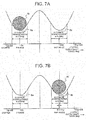
- FIGS. 7A, 7B , 8A and 8B respectively illustrate modifications with different control target positions.
- FIGS. 7A and 8A schematically shows a state before the shifting operation
- each of FIGS. 7B and 8B shows a control target position after the shifting operation.
- the control target position is slightly before (within the automatic drawing range) of the bottom position of groove 6b corresponding to the NotP range. That is, suppose the output shaft angle of the bottom position of groove 6a corresponding to P range is Dp [deg], control is performed in such a manner that the speed of roller 6c in a state in which the control target position is at the output shaft angle (Dnp [deg]-X) is substantially zero. Here, a relationship of "X ⁇ ⁇ D [deg]" is established. From the position at which roller 6c stops to the bottom position, automatic drawing is performed by a repulsive force of detent spring 6-2.
- roller 6c In a case in which control is performed in such a manner that the speed, that is, energy of the velocity, of roller 6c is substantially zero before the bottom position of the NotP range, roller 6c can be moved to the bottom position of groove 6b quietly by using automatic drawing by the repulsive force of detent spring 6-2, thereby reducing collision noise occurring when detent mechanism 6 moves to groove 6b.
- FIGS. 8A and 8B illustrate another variation in which the control target position is set at a previous stop position. Specifically, the timing of switching from driving to braking of actuator 3 and a set value of a braking force are learned, and next control is performed based on the learned set value.
- the braking force is learned from a previous switching timing from driving to braking, a previous stop position, the speed of roller 6c when roller 6c reaches the target bottom position, and the amount (angle) of overshooting from the target bottom position, for example.
- This learned value can be stored using, as a parameter, at least one of a power supply voltage of actuator 3 or the temperature of actuator 3. Control is performed in such a manner that the speed, or energy of the velocity, of roller 6c when roller 6c reaches the control target position is substantially zero.
- FIG. 9A schematically illustrates a contact portion where roller 6c and detent plate 6-1 are in contact with each other.
- roller 6c is biased by detent spring 6-2 toward the bottom positions of grooves 6a and 6b under pressure.
- the bottom position of groove 6b corresponding to the NotP range is, for example, at an output shaft angle of Dnp [deg] and has an automatic drawing range of ⁇ D [deg] in a manner similar to the P range.
- Stopper 16-1 is disposed at an output shaft angle of Dp - ⁇ S [deg]
- stopper 16-2 is disposed at an output shaft angle of Dnp + ⁇ S [deg].
- the manipulated variable of actuator 3 rapidly increases as illustrated in FIG. 9B , and maximum driving is then performed on actuator 3. Then, from the change in speed, the speed of roller 6c when roller 6c reaches a target position (time t1) is estimated, and an output shaft angle at the start of braking is determined in accordance with the estimated speed. When roller 6c reaches the output shaft angle at the start of braking (time t2), maximum braking is performed so that roller 6c stops at the target position. At this time, a deceleration degree for use in estimating the speed is changed (corrected) in accordance with the temperature of actuator 3.
- actuator 3 is reversely driven (braked) in such a manner the speed, that is, energy of the velocity, of roller 6c when roller 6c reaches the target position is substantially zero.
- the control target position is time t2.
- the control target position may be before the lower limit of the bottom of the NotP range (within automatic drawing range) as in the variation described above or may be at a previous stop position.
- the response time can be reduced with suppressed occurrence of collision noise.
- the vehicle starts in a stopped state in which collision noise is easily heard, that is, the shifting operation from the P range to the NotP range is performed.
- the shifting operation from the P range to the NotP range is performed.
- similar control can be, of course, performed in the case of performing a shifting operation from the NotP range to the P range.
Landscapes
- Engineering & Computer Science (AREA)
- General Engineering & Computer Science (AREA)
- Mechanical Engineering (AREA)
- Gear-Shifting Mechanisms (AREA)
- Control Of Transmission Device (AREA)
Abstract
Description
- The present invention relates to a range switching device for switching a range of an automatic transmission by using an actuator electrically controlled to be driven, and a switching method thereof.
- A known conventional range switching device switches a range of an automatic transmission by driving an actuator in response to a shifting operation by a driver (see, for example, Patent Document 1).
Patent Document 1 discloses a technique for learning a control target position of each range. In this technique, in a state positioned by a detent mechanism, a target angle in a current range is learned based on an angle of a range switching shaft (angle of a bottom position) detected by a potentiometer. -
Patent Document 2 describes a shift control system for correcting an output value of an encoder to an absolute position by bringing a detent plate and a roller of a detent spring into contact with each other, detecting a contact position thereof, and learning a limit position (wall position) of an operation range as a reference value. InPatent Document 2, feedback control is performed by using a deviation between a current position of an output shaft angle and a target position. -
- Patent Document 1:
Japanese Patent Application Laid-open Publication No. 2004-092851 - Patent Document 2:
Japanese Patent Application Laid-open Publication No. 2004-308752 - In a range switching device and a shift control system of these types, a control constant of an electric actuator is applied while focusing on shifting responsiveness in general.
- In this configuration, however, since the detent mechanism performs positioning by pressing the roller with the detent spring against the detent plate having a groove corresponding to a range, when the roller moves into the groove corresponding to the range and falls on a bottom position of the groove across a top thereof, a repulsive force of the detent spring is applied, and collision noise occurs when the roller reaches a target bottom position. Thus, in application to a vehicle that is very quiet, such as an electric vehicle (EV), this mechanism becomes a noise source, thus impairing marketability.
- The present invention has been made in view of the foregoing problems, and has an object of providing a range switching device and a switching method for an automatic transmission that can reduce collision noise caused by a detent mechanism.
- A range switching device of an automatic transmission according to the present invention is used for the automatic transmission including a detent mechanism that presses a roller against a groove by using a spring, moves the roller between grooves, and determines a range position of the transmission that is changed by driving the detent mechanism by an actuator, and in changing the range position of the transmission, the actuator is braked in accordance with a drawing force of the spring into a groove.
- A range switching method for an automatic transmission according to the present invention is used for the automatic transmission including a detent mechanism that presses a roller against a groove by using a spring, moves the roller between grooves, and determines a range position of the transmission that is changed by driving the detent mechanism by an actuator, and the method includes: driving the detent mechanism by the actuator; and braking the actuator in accordance with a drawing force of the spring into a groove.
- According to the present invention, in changing the range position of the transmission, the actuator is braked in accordance with the drawing force of the spring into the groove so that energy of the velocity can be controlled to approach zero when the roller reaches a target stop position. Thus, collision noise occurring when the roller collides with a groove of a detent plate can be reduced.
-
-
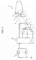
FIG. 1 is a system configuration diagram illustrating a range switching device of an automatic transmission according to an embodiment of the present invention. -
FIG. 2 is a perspective view illustrating an example configuration of a region enclosed by a broken line inFIG. 1 . -
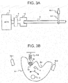
FIGS. 3A and 3B illustrate an extracted power transmission path from an actuator to a detent mechanism inFIG. 2 . -
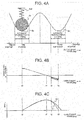
FIGS. 4A to 4C illustrate a first control example of an actuator in the range switching device of the automatic transmission according to the embodiment of the present invention. -
FIG. 5 is a characteristic diagram demonstrating a relationship between an output shaft angle and a response time. -
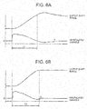
FIGS. 6A and 6B are characteristic diagrams demonstrating measurement results of output shaft angles and manipulated variables in a conventional range switching device of an automatic transmission and the range switching device of the automatic transmission according to the embodiment of the present invention in comparison. -
FIGS. 7A and 7B schematically illustrate a relationship between a detent plate and a roller in a case in which a control target position is before a lower limit position of a groove. -
FIGS. 8A and 8B schematically illustrate a relationship between the detent plate and the roller in a case in which the control target position is a previous stop position. -
FIGS. 9A and 9B illustrate a second control example of the actuator in the range switching device of the automatic transmission according to the embodiment of the present invention. - An embodiment of the present invention will be described with reference to the drawings.
- In a range switching device of an automatic transmission illustrated in
FIG. 1 , anautomatic transmission 1 to be installed in a vehicle includes an actuator (motor) 3 for park by wire (PBW) to drive a range switching valve.Actuator 3 sets the vehicle in a parking lock state by a shifting operation of a driver, e.g., shifting from not-parking (NotP range) such as a D range to parking (P range), or sets the vehicle in a movable state by a shifting operation from the P range to the NotP range. That is,actuator 3 mechanically locks or unlocks a transmission or a reduction gear. - The output shaft of
actuator 3 is provided with adeceleration gear mechanism 4, andactuator 3 rotatably drives arange switching shaft 5 throughdeceleration gear mechanism 4.Range switching shaft 5 is provided with adetent mechanism 6, a potentiometer 7, and aninhibitor switch 8, for example.Detent mechanism 6 positionsrange switching shaft 5 at angles respectively corresponding to the P range and the NotP range. Potentiometer 7 successively detects the angles ofrange switching shaft 5, andinhibitor switch 8 detects which one of the P range or the NotP rangeautomatic transmission 1 is switched to. - In addition, a
range switching switch 9 for outputting range position signals respectively corresponding to range positions P, R, N, D, 2, and 1 when the driver performs a shifting operation is also provided. - A signal output from potentiometer 7 and corresponding to a rotation angle of
range switching shaft 5, a signal output frominhibitor switch 8 and indicating which one of the P range or the NotP rangeautomatic transmission 1 is switched to, and a range position signal output fromrange switching switch 9 are input to an A/T control unit (A/T C/U) 10. In response to a range switching request determined based on a range position signal ofrange switching switch 9, A/T control unit 10controls actuator 3 so thatactuator 3 drives. - Specifically, proportional-integral (PI) control is performed in accordance with a deviation between a target angle of
range switching shaft 5 required byrange switching switch 9 and an actual angle detected by potentiometer (output shaft angle sensor) 7, and a driving signal (duty driving signal for turning power supply on or off at high frequency) is supplied toactuator 3 to perform feedback control. -
FIG. 2 illustrates an example configuration of aregion 2 enclosed by a broken line inFIG. 1 .Detent mechanism 6 includes a detent plate 6-1 that is fixed torange switching shaft 5 and configured to rotate integrally withrange switching shaft 5 and a detent spring (spring) 6-2 that supports aroller 6c engaged withgrooves biases roller 6c toward the bottom positions ofgrooves Detent mechanism 6 positionsrange switching shaft 5 at an angle corresponding to one of the P range or the NotP range. - Detent plate 6-1 is attached to one end of an L-
shaped rod 11, and acam 13 is attached to the other end ofrod 11. Aparking pawl 12 is swingably supported and is driven to swing while being in slidable contact withcam 13. When a shifting operation from the NotP range to the P range is performed,roller 6c moves fromgroove 6b to groove 6a and becomes engaged withgroove 6a. At this time,rod 11 is pressed in the direction of an arrow A, and a tapered portion ofcam 13 pushesparking pawl 12 upward in the direction of an arrow B so that aprojection 12a ofparking pawl 12 becomes engaged with arecess 14a of aparking gear 14 and, thereby,parking gear 14 is fixed. -
FIGS. 3A and 3B illustrates an extracted power transmission path fromactuator 3 todetent mechanism 6 inFIG. 2 ,FIG. 3A is a front view, andFIG. 3B is a side view seen from the detent plate inFIG. 3A . A driving force of actuator (ACTR) 3 is transmitted torange switching shaft 5 by aspline 15, andrange switching shaft 5 rotates to cause detent plate 6-1 to rotate in the direction of an arrow C. In this manner,roller 6c reciprocates betweengroove 6a formed in detent plate 6-1 and corresponding to the P range andgroove 6b formed in detent plate 6-1 and corresponding to the NotP range. Here,roller 6c is biased under pressure toward the bottom positions ofgrooves roller 6c moves fromgroove 6a to groove 6b across the top. - A predetermined amount of play is provided in a rotation direction in a portion where
spline 15 andrange switching shaft 5 are coupled to each other. Stoppers 16-1 and 16-2 for restricting rotation of detent plate 6-1 are provided at both sides of detent plate 6-1. - Control of
actuator 3 in the range switching device having the configuration described above will be specifically described with reference toFIGS. 4A to 4C. FIG. 4A schematically illustrates a contact portion betweenroller 6c and detent plate 6-1. In this example, a shifting operation from the P range to the NotP range is performed.Roller 6c is biased downward by detent spring 6-2 toward the lower limit position (bottom position) ofgroove 6a under pressure. Suppose an angle (output shaft angle) ofrange switching shaft 5 is Dp [deg] whenroller 6c is at the bottom position ofgroove 6a corresponding to the P range, as long as the angle is within ±ΔD [deg], pressing by detent spring 6-2causes roller 6c to be automatically drawn to the bottom position ofgroove 6a in detent plate 6-1 even when driving ofactuator 3 is stopped (automatic drawing range). - The output shaft angle of the lower limit position (bottom position) of
groove 6b corresponding to the NotP range is at Dnp [deg], for example, this bottom position is set as a control target position (target stop position), and control is performed so that the speed, that is, energy of the velocity, ofroller 6c is zero when the output shaft angle is Dnp [deg]. In a manner similar to the P range, the NotP range has an automatic drawing range of ±ΔD [deg]. - The output shaft angle of stopper 16-1 is Dp - ΔS [deg], and the output shaft angle of stopper 16-2 is Dnp + ΔS [deg].
- When the driver performs a shifting operation from the P range to the D range (NotP range), as illustrated in
FIG. 4B , a manipulated variable ofactuator 3 rapidly increases (at time t0), and gradually decreases with movement ofroller 6c. As this control, PI control is employed, and a control constant focusing on responsiveness of the actuator is applied. Whenroller 6c moves across the top and descends toward the bottom ofgroove 6b,actuator 3 is braked at time t1, for example. Subsequently, whenroller 6c reaches the automatic drawing range (at time t2), a braking force corresponding to a hatched region between times t2 and t3 is added to the manipulated variable in consideration of a drawing force of detent spring 6-2. - That is, the greatest force is needed when
roller 6c moves out of the bottom position, and a driving force is then gradually reduced. Thereafter, when the driving force is reduced to some degree at time t1,actuator 3 is driven to be reversed and is braked. At this time, in consideration of a repulsive force of detent spring 6-2, a force of drawing by detent spring 6-2 is added to the braking force from a midpoint (time t2). - As a timing of braking, for example, the driving speed of
actuator 3 is obtained (calculated from the amount of change of the output shaft angle), the speed ofroller 6c whenroller 6c reaches a target bottom position with a maximum braking force being applied toactuator 3 at a current output shaft angle is estimated, and when the estimated speed satisfies a condition, the maximum braking force is applied toactuator 3. The condition is that the speed ofroller 6c whenroller 6c reaches a target bottom position (output shaft angle = Dnp [deg]) is substantially zero or that the speed ofroller 6c whenroller 6c reaches the target bottom position becomes zero and then changes to a positive value. - Since the driving force and the braking force of
actuator 3 change depending on a power supply voltage and a temperature ofactuator 3, movement ofroller 6c changes. Thus, the estimated speed ofroller 6c whenroller 6c reaches the target bottom position is corrected in accordance with the power supply voltage and the temperature ofactuator 3. Specifically, when the power supply voltage ofactuator 3 is high, the braking force is increased, whereas when the power supply voltage is low, the braking force is reduced. In addition, when the temperature ofactuator 3 is high, the braking force is increased, whereas when the temperature is low, the braking force is reduced. In this manner, the braking force is corrected in consideration of variations depending on the power supply voltage and the temperature ofactuator 3. - In
detent mechanism 6, the configuration of detent plate 6-1 and a repulsive force of detent spring 6-2 cause the repulsive force of detent spring 6-2 to act strongly whenroller 6c enters the automatic drawing range. - In view of this, in the first control example, in addition to PI control focusing on responsiveness, a drawing force to the bottom position in the groove by detent spring 6-2 is added to the braking force. In this manner, the braking force is increased in accordance with the force of drawing
roller 6c to bottom position ofgroove 6b so that the speed ofroller 6c whenroller 6c reaches the target bottom position substantially approaches zero, as illustrated by a solid line V1 inFIG. 4C , and stops at bottom position ofgroove 6b quietly. The braking force is corrected in consideration of variations depending on the power supply voltage and the temperature ofactuator 3 so that the braking force can be more accurately controlled. - If the repulsive force of detent spring 6-2 were not taken into consideration, the energy of the velocity would remain when
roller 6c reaches the target bottom position as illustrated in a solid line V2, and thus, collision noise would occur. -
FIG. 5 shows a relationship between an output shaft angle and a response time when a shifting operation from the P range to the D range is performed. InFIG. 5 , a solid line L1 corresponds to the embodiment, a dash-dot line L2 corresponds to a case in which a control constant is applied while focusing on shifting responsiveness, and a broken line L3 corresponds to a case in which a control constant is applied while focusing on quietness, in the relationship between the output shaft angle and the response time. In the case of focusing on shifting responsiveness, as indicated by dash-dot line L2, the target position (NotP range) is overshot and then change of the output shaft angle is converged in a relatively short period. However, collision noise occurs at overshooting. On the other hand, in PI control focusing on quietness, as indicated by broken line L3, the output shaft angle gently changes and collision noise is less likely to occur, but the response time is long. - On the other hand, as illustrated in solid line L1, after
roller 6c has moved across the top,actuator 3 is braked in consideration of a drawing force intogroove 6b by detent spring 6-2 so that the output shaft angle is caused to change gently to suppress generation of collision noise and an increase of the response time can be reduced. In this manner, both quietness and responsiveness can be achieved. -
FIGS. 6A and 6B illustrate a relationship between an output shaft angle and a manipulated variable with a comparison of measurement results between a (conventional) case in which a control constant is applied while focusing on shifting responsiveness and the first control example of the embodiment of the present invention. As illustrated inFIG. 6A , in the conventional example, although time T1 of 100% response is short, overshooting then occurs in the output shaft angle, and an operation is performed after a lapse of time T1 of 100% response. After a lapse of a predetermined time, the manipulated variable becomes zero. - On the other hand, as illustrated in
FIG. 6B , in this embodiment, although a time T2 of 100% response is relatively long, no overshooting occurs in the output shaft angle, and the manipulated variable is substantially zero after a lapse of time T2 of 100% response. - In the first control example described above, the control target position (target stop position) is the lower limit position (bottom position) of the groove.
FIGS. 7A, 7B ,8A and 8B respectively illustrate modifications with different control target positions. Here, an example in which a shifting operation from the P range to the NotP range will be described. Each ofFIGS. 7A and8A schematically shows a state before the shifting operation, and each ofFIGS. 7B and8B shows a control target position after the shifting operation. - In
FIGS. 7A and 7B , the control target position is slightly before (within the automatic drawing range) of the bottom position ofgroove 6b corresponding to the NotP range. That is, suppose the output shaft angle of the bottom position ofgroove 6a corresponding to P range is Dp [deg], control is performed in such a manner that the speed ofroller 6c in a state in which the control target position is at the output shaft angle (Dnp [deg]-X) is substantially zero. Here, a relationship of "X < ΔD [deg]" is established. From the position at whichroller 6c stops to the bottom position, automatic drawing is performed by a repulsive force of detent spring 6-2. - In a case in which control is performed in such a manner that the speed, that is, energy of the velocity, of
roller 6c is substantially zero before the bottom position of the NotP range,roller 6c can be moved to the bottom position ofgroove 6b quietly by using automatic drawing by the repulsive force of detent spring 6-2, thereby reducing collision noise occurring whendetent mechanism 6 moves to groove 6b. -
FIGS. 8A and 8B illustrate another variation in which the control target position is set at a previous stop position. Specifically, the timing of switching from driving to braking ofactuator 3 and a set value of a braking force are learned, and next control is performed based on the learned set value. The braking force is learned from a previous switching timing from driving to braking, a previous stop position, the speed ofroller 6c whenroller 6c reaches the target bottom position, and the amount (angle) of overshooting from the target bottom position, for example. This learned value can be stored using, as a parameter, at least one of a power supply voltage ofactuator 3 or the temperature ofactuator 3. Control is performed in such a manner that the speed, or energy of the velocity, ofroller 6c whenroller 6c reaches the control target position is substantially zero. - Since there is provided play due to backlash of
spline 15, even whenroller 6c has stopped at the bottom position ofgroove 6b, the output shaft angle might fail to be precisely Dnp [deg], and thus, a position whereroller 6c actually previously stopped is set as a target. - In this manner, play provided in the power transmission path from
actuator 3 todetent mechanism 6 and an influence of, for example, abrasion due to aging can be reduced so that precision can be enhanced. - In a second control example of
actuator 3 illustrated inFIGS. 9A and 9B , maximum driving is performed onactuator 3, and then maximum braking is performed onactuator 3.FIG. 9A schematically illustrates a contact portion whereroller 6c and detent plate 6-1 are in contact with each other. In this case, in a manner similar toFIG. 4A , a shifting operation from the P range to the NotP range is performed.Roller 6c is biased by detent spring 6-2 toward the bottom positions ofgrooves range switching shaft 5 is Dp [deg] whenroller 6c is at the bottom position ofgroove 6a corresponding to the P range,roller 6c is automatically drawn to the bottom position ofgroove 6a of detent plate 6-1 by pressing by detent spring 6-2 as long as the angle is within ±ΔD [deg] (automatic drawing range). - The bottom position of
groove 6b corresponding to the NotP range is, for example, at an output shaft angle of Dnp [deg] and has an automatic drawing range of ±ΔD [deg] in a manner similar to the P range. Stopper 16-1 is disposed at an output shaft angle of Dp -ΔS [deg], and stopper 16-2 is disposed at an output shaft angle of Dnp + ΔS [deg]. - When the driver performs a shifting operation from the P range to the D range (NotP range), the manipulated variable of
actuator 3 rapidly increases as illustrated inFIG. 9B , and maximum driving is then performed onactuator 3. Then, from the change in speed, the speed ofroller 6c whenroller 6c reaches a target position (time t1) is estimated, and an output shaft angle at the start of braking is determined in accordance with the estimated speed. Whenroller 6c reaches the output shaft angle at the start of braking (time t2), maximum braking is performed so thatroller 6c stops at the target position. At this time, a deceleration degree for use in estimating the speed is changed (corrected) in accordance with the temperature ofactuator 3. Thereafter,actuator 3 is reversely driven (braked) in such a manner the speed, that is, energy of the velocity, ofroller 6c whenroller 6c reaches the target position is substantially zero. In the case ofFIGS. 9A and 9B , the control target position is time t2. Alternatively, the control target position may be before the lower limit of the bottom of the NotP range (within automatic drawing range) as in the variation described above or may be at a previous stop position. - In the second control example, the response time can be reduced with suppressed occurrence of collision noise.
- In the first and second control examples and the variation described above, the vehicle starts in a stopped state in which collision noise is easily heard, that is, the shifting operation from the P range to the NotP range is performed. For a vehicle having high quietness, such as an EV, similar control can be, of course, performed in the case of performing a shifting operation from the NotP range to the P range.
-
- 1
- automatic transmission
- 3
- actuator (motor)
- 6
- detent mechanism
- 6-1
- detent plate
- 6-2
- detent spring (spring)
- 6a, 6b
- groove
- 6c
- roller
Claims (15)
- A range switching device of an automatic transmission, the automatic transmission including a detent mechanism that presses a roller against a groove by using a spring, moves the roller between grooves, and determines a range position of the transmission, the range position of the transmission being changed by driving the detent mechanism by an actuator, wherein
in changing the range position of the transmission, the actuator is braked in accordance with a drawing force of the spring into a groove. - The range switching device of the automatic transmission of claim 1, wherein
at least one of a timing of switching from driving to braking of the actuator or a braking force of the actuator is changed in accordance with at least one of a power supply voltage applied to the actuator or a temperature of the actuator. - The range switching device of the automatic transmission of claim 2, wherein
the braking force is increased when the power supply voltage of the actuator increases, and
the braking force is reduced when the power supply voltage of the actuator decreases. - The range switching device of the automatic transmission of claim 2, wherein
the braking force is increased when the temperature of the actuator increases, and
the braking force is reduced when the temperature of the actuator decreases. - The range switching device of an automatic transmission of claim 1, wherein
braking of the actuator is stopped at at least one of a lower limit position of the groove, a position before the lower limit position of the groove and within a range of automatic drawing by the spring, or a previous stop position. - The range switching device of the automatic transmission of claim 1, wherein
a timing of switching from driving to braking of the actuator and a set value of a braking force are learned, and
next control is performed based on the learned set value. - The range switching device of the automatic transmission of claim 6, wherein
the set value of the braking force is learned from at least one of a previous timing of switching from driving to braking and a previous stop position, a speed of the roller when the roller reaches a target bottom position, or an amount of overshooting from the target bottom position. - The range switching device of the automatic transmission of claim 1, wherein
a timing of switching from driving to braking of the actuator is set based on a maximum braking force of the actuator. - A range switching method for an automatic transmission, the automatic transmission including a detent mechanism that presses a roller against a groove by using a spring, moves the roller between grooves, and determines a range position of the transmission, the range position of the transmission being changed by driving the detent mechanism by an actuator, the method comprising:driving the detent mechanism by the actuator; andbraking the actuator in accordance with a drawing force of the spring into a groove.
- The range switching method of the automatic transmission of claim 9, wherein
the driving the actuator is driving the actuator so that the actuator rotates reversely. - The range switching method of the automatic transmission of claim 10, wherein
in the driving the actuator so that the actuator rotates reversely, a force corresponding to the drawing force of the spring is added to a repulsive force of the spring. - The range switching method of the automatic transmission of claim 10, wherein
the driving the actuator so that the actuator rotates reversely includes
calculating a braking force by PI control focusing on responsiveness,
calculating a braking force corresponding to a drawing force of the spring to a bottom position in a groove, and
adding the calculated braking force, and
the actuator is driven to rotate reversely based on a result of the addition. - The range switching method of the automatic transmission of claim 9, wherein
the braking the actuator includes
obtaining a driving speed of the actuator, and
estimating a speed of the roller when the roller reaches a target bottom position in a case in which a maximum braking force is applied to the actuator at a current output shaft angle, and
the maximum braking force is applied to the actuator when the estimated speed satisfies a condition. - The range switching method of the automatic transmission of claim 13, wherein
the obtaining the driving speed of the actuator is calculating the driving speed of the actuator from an amount of change of an output shaft angle of the actuator. - The range switching method of the automatic transmission of claim 9, further comprising, after the braking the actuator,
stopping the braking at at least one of a lower limit position of the groove, a position before the lower limit position of the groove and within a range of automatic drawing by the spring, or a previous stop position.
Applications Claiming Priority (2)
| Application Number | Priority Date | Filing Date | Title |
|---|---|---|---|
| JP2013220969A JP6173875B2 (en) | 2013-10-24 | 2013-10-24 | Automatic transmission range switching device |
| PCT/JP2014/074947 WO2015060048A1 (en) | 2013-10-24 | 2014-09-19 | Range switching device for automatic transmission and switching method therefor |
Publications (3)
| Publication Number | Publication Date |
|---|---|
| EP3061997A1 true EP3061997A1 (en) | 2016-08-31 |
| EP3061997A4 EP3061997A4 (en) | 2017-08-30 |
| EP3061997B1 EP3061997B1 (en) | 2019-03-13 |
Family
ID=52992652
Family Applications (1)
| Application Number | Title | Priority Date | Filing Date |
|---|---|---|---|
| EP14855392.8A Not-in-force EP3061997B1 (en) | 2013-10-24 | 2014-09-19 | Range switching device for automatic transmission and switching method therefor |
Country Status (5)
| Country | Link |
|---|---|
| US (1) | US10690243B2 (en) |
| EP (1) | EP3061997B1 (en) |
| JP (1) | JP6173875B2 (en) |
| CN (1) | CN105659006B (en) |
| WO (1) | WO2015060048A1 (en) |
Cited By (2)
| Publication number | Priority date | Publication date | Assignee | Title |
|---|---|---|---|---|
| WO2020094813A1 (en) * | 2018-11-08 | 2020-05-14 | Renault S.A.S | Method and device for checking the engagement of a parking brake finger |
| EP4075028A1 (en) * | 2021-04-16 | 2022-10-19 | Aisin Corporation | Shift device |
Families Citing this family (16)
| Publication number | Priority date | Publication date | Assignee | Title |
|---|---|---|---|---|
| JP6173875B2 (en) | 2013-10-24 | 2017-08-02 | 日立オートモティブシステムズ株式会社 | Automatic transmission range switching device |
| JP6601322B2 (en) * | 2016-06-24 | 2019-11-06 | 株式会社デンソー | Shift range switching device |
| JP6583299B2 (en) * | 2017-01-26 | 2019-10-02 | トヨタ自動車株式会社 | Control device for hybrid vehicle |
| DE102017202647A1 (en) * | 2017-02-20 | 2018-08-23 | Zf Friedrichshafen Ag | A method for driving an actuator for a vehicle, control unit and parking brake device for a vehicle |
| US11280400B2 (en) * | 2017-05-24 | 2022-03-22 | Ghsp, Inc. | Transmission shifter with improved feel positioner |
| JP6939462B2 (en) * | 2017-11-20 | 2021-09-22 | 株式会社デンソー | Shift range switching system |
| JP7028014B2 (en) * | 2018-03-26 | 2022-03-02 | 日本電産トーソク株式会社 | Shift range switching controller |
| KR102202955B1 (en) * | 2018-11-27 | 2021-01-14 | 주식회사 현대케피코 | Apparatus and method for controlling motor of electric shift by wire system |
| DE102018133266A1 (en) | 2018-12-20 | 2020-06-25 | Fte Automotive Gmbh | Gear housing with electromechanical parking lock actuator |
| JP7211270B2 (en) * | 2019-06-10 | 2023-01-24 | 株式会社デンソー | shift range controller |
| JP7188347B2 (en) * | 2019-10-01 | 2022-12-13 | 株式会社デンソー | shift range controller |
| CN110949142B (en) * | 2019-12-09 | 2021-10-22 | 北理慧动(常熟)车辆科技有限公司 | A kind of AMT shift process control method |
| JP7415794B2 (en) * | 2020-05-21 | 2024-01-17 | 株式会社デンソー | Power transmission switching device |
| JP7453122B2 (en) * | 2020-11-06 | 2024-03-19 | トヨタ自動車株式会社 | shift-by-wire system |
| CN114811032B (en) * | 2022-05-30 | 2024-06-21 | 东风汽车有限公司东风日产乘用车公司 | Gear self-learning method, device, equipment and storage medium |
| US20240351570A1 (en) * | 2023-04-19 | 2024-10-24 | Sumitomo Wiring Systems, Ltd. | Power Supply System Having A Shut-Off Circuit |
Family Cites Families (13)
| Publication number | Priority date | Publication date | Assignee | Title |
|---|---|---|---|---|
| JP3201116B2 (en) * | 1993-12-28 | 2001-08-20 | トヨタ自動車株式会社 | Stop control device for range switching valve of automatic transmission |
| JP2001182828A (en) * | 1999-12-27 | 2001-07-06 | Aisin Aw Co Ltd | Range changer for automatic transmission |
| TW541605B (en) * | 2000-07-07 | 2003-07-11 | Hitachi Ltd | Fabrication method of semiconductor integrated circuit device |
| JP2003148599A (en) * | 2001-11-09 | 2003-05-21 | Hitachi Unisia Automotive Ltd | Electric range switching device for automatic transmission |
| JP2003148608A (en) * | 2001-11-14 | 2003-05-21 | Hitachi Unisia Automotive Ltd | Electric range switching device for automatic transmission |
| JP2003156144A (en) * | 2001-11-20 | 2003-05-30 | Hitachi Unisia Automotive Ltd | Electric range switching device for automatic transmission |
| JP2004092851A (en) | 2002-09-03 | 2004-03-25 | Hitachi Unisia Automotive Ltd | Range changer for automatic transmission |
| JP4248290B2 (en) | 2003-04-04 | 2009-04-02 | 株式会社デンソー | Shift control system and shift control method |
| US7367244B2 (en) * | 2003-10-29 | 2008-05-06 | Calsonic Kansei Corporation | Operating position select device for automatic transmission |
| JP2007107673A (en) * | 2005-10-14 | 2007-04-26 | Aisin Aw Co Ltd | Control device of range switching device |
| JP5789952B2 (en) * | 2010-10-21 | 2015-10-07 | 株式会社デンソー | Motor control device |
| JP2013143822A (en) * | 2012-01-10 | 2013-07-22 | Denso Corp | Motor control device |
| JP6173875B2 (en) | 2013-10-24 | 2017-08-02 | 日立オートモティブシステムズ株式会社 | Automatic transmission range switching device |
-
2013
- 2013-10-24 JP JP2013220969A patent/JP6173875B2/en not_active Expired - Fee Related
-
2014
- 2014-09-19 WO PCT/JP2014/074947 patent/WO2015060048A1/en not_active Ceased
- 2014-09-19 EP EP14855392.8A patent/EP3061997B1/en not_active Not-in-force
- 2014-09-19 CN CN201480055552.0A patent/CN105659006B/en not_active Expired - Fee Related
- 2014-09-19 US US15/028,312 patent/US10690243B2/en not_active Expired - Fee Related
Cited By (4)
| Publication number | Priority date | Publication date | Assignee | Title |
|---|---|---|---|---|
| WO2020094813A1 (en) * | 2018-11-08 | 2020-05-14 | Renault S.A.S | Method and device for checking the engagement of a parking brake finger |
| FR3088401A1 (en) * | 2018-11-08 | 2020-05-15 | Renault S.A.S. | METHOD AND DEVICE FOR CONTROLLING THE ENGAGEMENT OF A PARKING FINGER |
| US11708907B2 (en) | 2018-11-08 | 2023-07-25 | Nissan Motor Co., Ltd. | Method and device for checking the engagement of a parking brake finger |
| EP4075028A1 (en) * | 2021-04-16 | 2022-10-19 | Aisin Corporation | Shift device |
Also Published As
| Publication number | Publication date |
|---|---|
| US10690243B2 (en) | 2020-06-23 |
| EP3061997A4 (en) | 2017-08-30 |
| JP6173875B2 (en) | 2017-08-02 |
| CN105659006A (en) | 2016-06-08 |
| WO2015060048A1 (en) | 2015-04-30 |
| EP3061997B1 (en) | 2019-03-13 |
| US20160298761A1 (en) | 2016-10-13 |
| CN105659006B (en) | 2017-03-01 |
| JP2015081665A (en) | 2015-04-27 |
Similar Documents
| Publication | Publication Date | Title |
|---|---|---|
| EP3061997B1 (en) | Range switching device for automatic transmission and switching method therefor | |
| JP6062298B2 (en) | Automatic transmission range switching device | |
| US9209729B2 (en) | Shift range switching apparatus | |
| CN110325769B (en) | gear shift control device | |
| US20190202417A1 (en) | Shift range switching device | |
| US10844952B2 (en) | Shift range control apparatus | |
| JP6104468B2 (en) | Automobile haptic accelerator pedal with elastically coupled actuator, method for closed-loop control of the haptic accelerator pedal, and closed-loop control unit | |
| US10615724B2 (en) | Shift range control apparatus | |
| US11837987B2 (en) | Motor control device | |
| CN111095781B (en) | gear shift control | |
| US20080129236A1 (en) | Motor control device | |
| JP2016100930A (en) | Motor control device | |
| KR20220024806A (en) | motor control unit | |
| US20170246931A1 (en) | Method for driving an actuator of an hvac system | |
| JP6443189B2 (en) | Shift range switching device | |
| US11614163B2 (en) | Motor control method and device for shift-by-wire system | |
| CN111630304B (en) | gear shift control device | |
| CN112368933A (en) | Shift gear control device | |
| CN112984000A (en) | Clutch actuator and method for controlling a clutch actuator | |
| JP2013187966A (en) | Motor controller | |
| JP4606488B2 (en) | Control device for clutch | |
| WO2019172212A1 (en) | Shift range control device | |
| CN104220772A (en) | Method and device for referencing and plausibility-checking a reference position of an actuator |
Legal Events
| Date | Code | Title | Description |
|---|---|---|---|
| PUAI | Public reference made under article 153(3) epc to a published international application that has entered the european phase |
Free format text: ORIGINAL CODE: 0009012 |
|
| 17P | Request for examination filed |
Effective date: 20160408 |
|
| AK | Designated contracting states |
Kind code of ref document: A1 Designated state(s): AL AT BE BG CH CY CZ DE DK EE ES FI FR GB GR HR HU IE IS IT LI LT LU LV MC MK MT NL NO PL PT RO RS SE SI SK SM TR |
|
| AX | Request for extension of the european patent |
Extension state: BA ME |
|
| DAX | Request for extension of the european patent (deleted) | ||
| A4 | Supplementary search report drawn up and despatched |
Effective date: 20170728 |
|
| RIC1 | Information provided on ipc code assigned before grant |
Ipc: F16H 61/32 20060101ALI20170724BHEP Ipc: F16H 63/38 20060101ALI20170724BHEP Ipc: F16H 59/08 20060101ALI20170724BHEP Ipc: F16H 61/28 20060101AFI20170724BHEP Ipc: F16H 61/02 20060101ALI20170724BHEP Ipc: F16H 63/34 20060101ALI20170724BHEP Ipc: F16H 59/68 20060101ALI20170724BHEP |
|
| GRAP | Despatch of communication of intention to grant a patent |
Free format text: ORIGINAL CODE: EPIDOSNIGR1 |
|
| STAA | Information on the status of an ep patent application or granted ep patent |
Free format text: STATUS: GRANT OF PATENT IS INTENDED |
|
| INTG | Intention to grant announced |
Effective date: 20181017 |
|
| GRAS | Grant fee paid |
Free format text: ORIGINAL CODE: EPIDOSNIGR3 |
|
| GRAA | (expected) grant |
Free format text: ORIGINAL CODE: 0009210 |
|
| STAA | Information on the status of an ep patent application or granted ep patent |
Free format text: STATUS: THE PATENT HAS BEEN GRANTED |
|
| AK | Designated contracting states |
Kind code of ref document: B1 Designated state(s): AL AT BE BG CH CY CZ DE DK EE ES FI FR GB GR HR HU IE IS IT LI LT LU LV MC MK MT NL NO PL PT RO RS SE SI SK SM TR |
|
| REG | Reference to a national code |
Ref country code: GB Ref legal event code: FG4D |
|
| REG | Reference to a national code |
Ref country code: CH Ref legal event code: EP Ref country code: AT Ref legal event code: REF Ref document number: 1108146 Country of ref document: AT Kind code of ref document: T Effective date: 20190315 |
|
| REG | Reference to a national code |
Ref country code: IE Ref legal event code: FG4D |
|
| REG | Reference to a national code |
Ref country code: DE Ref legal event code: R096 Ref document number: 602014043010 Country of ref document: DE |
|
| REG | Reference to a national code |
Ref country code: NL Ref legal event code: MP Effective date: 20190313 |
|
| REG | Reference to a national code |
Ref country code: LT Ref legal event code: MG4D |
|
| PG25 | Lapsed in a contracting state [announced via postgrant information from national office to epo] |
Ref country code: SE Free format text: LAPSE BECAUSE OF FAILURE TO SUBMIT A TRANSLATION OF THE DESCRIPTION OR TO PAY THE FEE WITHIN THE PRESCRIBED TIME-LIMIT Effective date: 20190313 Ref country code: NO Free format text: LAPSE BECAUSE OF FAILURE TO SUBMIT A TRANSLATION OF THE DESCRIPTION OR TO PAY THE FEE WITHIN THE PRESCRIBED TIME-LIMIT Effective date: 20190613 Ref country code: FI Free format text: LAPSE BECAUSE OF FAILURE TO SUBMIT A TRANSLATION OF THE DESCRIPTION OR TO PAY THE FEE WITHIN THE PRESCRIBED TIME-LIMIT Effective date: 20190313 Ref country code: LT Free format text: LAPSE BECAUSE OF FAILURE TO SUBMIT A TRANSLATION OF THE DESCRIPTION OR TO PAY THE FEE WITHIN THE PRESCRIBED TIME-LIMIT Effective date: 20190313 |
|
| PG25 | Lapsed in a contracting state [announced via postgrant information from national office to epo] |
Ref country code: BG Free format text: LAPSE BECAUSE OF FAILURE TO SUBMIT A TRANSLATION OF THE DESCRIPTION OR TO PAY THE FEE WITHIN THE PRESCRIBED TIME-LIMIT Effective date: 20190613 Ref country code: GR Free format text: LAPSE BECAUSE OF FAILURE TO SUBMIT A TRANSLATION OF THE DESCRIPTION OR TO PAY THE FEE WITHIN THE PRESCRIBED TIME-LIMIT Effective date: 20190614 Ref country code: NL Free format text: LAPSE BECAUSE OF FAILURE TO SUBMIT A TRANSLATION OF THE DESCRIPTION OR TO PAY THE FEE WITHIN THE PRESCRIBED TIME-LIMIT Effective date: 20190313 Ref country code: RS Free format text: LAPSE BECAUSE OF FAILURE TO SUBMIT A TRANSLATION OF THE DESCRIPTION OR TO PAY THE FEE WITHIN THE PRESCRIBED TIME-LIMIT Effective date: 20190313 Ref country code: HR Free format text: LAPSE BECAUSE OF FAILURE TO SUBMIT A TRANSLATION OF THE DESCRIPTION OR TO PAY THE FEE WITHIN THE PRESCRIBED TIME-LIMIT Effective date: 20190313 Ref country code: LV Free format text: LAPSE BECAUSE OF FAILURE TO SUBMIT A TRANSLATION OF THE DESCRIPTION OR TO PAY THE FEE WITHIN THE PRESCRIBED TIME-LIMIT Effective date: 20190313 |
|
| REG | Reference to a national code |
Ref country code: AT Ref legal event code: MK05 Ref document number: 1108146 Country of ref document: AT Kind code of ref document: T Effective date: 20190313 |
|
| PG25 | Lapsed in a contracting state [announced via postgrant information from national office to epo] |
Ref country code: RO Free format text: LAPSE BECAUSE OF FAILURE TO SUBMIT A TRANSLATION OF THE DESCRIPTION OR TO PAY THE FEE WITHIN THE PRESCRIBED TIME-LIMIT Effective date: 20190313 Ref country code: IT Free format text: LAPSE BECAUSE OF FAILURE TO SUBMIT A TRANSLATION OF THE DESCRIPTION OR TO PAY THE FEE WITHIN THE PRESCRIBED TIME-LIMIT Effective date: 20190313 Ref country code: CZ Free format text: LAPSE BECAUSE OF FAILURE TO SUBMIT A TRANSLATION OF THE DESCRIPTION OR TO PAY THE FEE WITHIN THE PRESCRIBED TIME-LIMIT Effective date: 20190313 Ref country code: SK Free format text: LAPSE BECAUSE OF FAILURE TO SUBMIT A TRANSLATION OF THE DESCRIPTION OR TO PAY THE FEE WITHIN THE PRESCRIBED TIME-LIMIT Effective date: 20190313 Ref country code: AL Free format text: LAPSE BECAUSE OF FAILURE TO SUBMIT A TRANSLATION OF THE DESCRIPTION OR TO PAY THE FEE WITHIN THE PRESCRIBED TIME-LIMIT Effective date: 20190313 Ref country code: EE Free format text: LAPSE BECAUSE OF FAILURE TO SUBMIT A TRANSLATION OF THE DESCRIPTION OR TO PAY THE FEE WITHIN THE PRESCRIBED TIME-LIMIT Effective date: 20190313 Ref country code: PT Free format text: LAPSE BECAUSE OF FAILURE TO SUBMIT A TRANSLATION OF THE DESCRIPTION OR TO PAY THE FEE WITHIN THE PRESCRIBED TIME-LIMIT Effective date: 20190713 Ref country code: ES Free format text: LAPSE BECAUSE OF FAILURE TO SUBMIT A TRANSLATION OF THE DESCRIPTION OR TO PAY THE FEE WITHIN THE PRESCRIBED TIME-LIMIT Effective date: 20190313 |
|
| PG25 | Lapsed in a contracting state [announced via postgrant information from national office to epo] |
Ref country code: SM Free format text: LAPSE BECAUSE OF FAILURE TO SUBMIT A TRANSLATION OF THE DESCRIPTION OR TO PAY THE FEE WITHIN THE PRESCRIBED TIME-LIMIT Effective date: 20190313 Ref country code: PL Free format text: LAPSE BECAUSE OF FAILURE TO SUBMIT A TRANSLATION OF THE DESCRIPTION OR TO PAY THE FEE WITHIN THE PRESCRIBED TIME-LIMIT Effective date: 20190313 |
|
| REG | Reference to a national code |
Ref country code: DE Ref legal event code: R097 Ref document number: 602014043010 Country of ref document: DE |
|
| PG25 | Lapsed in a contracting state [announced via postgrant information from national office to epo] |
Ref country code: IS Free format text: LAPSE BECAUSE OF FAILURE TO SUBMIT A TRANSLATION OF THE DESCRIPTION OR TO PAY THE FEE WITHIN THE PRESCRIBED TIME-LIMIT Effective date: 20190713 Ref country code: AT Free format text: LAPSE BECAUSE OF FAILURE TO SUBMIT A TRANSLATION OF THE DESCRIPTION OR TO PAY THE FEE WITHIN THE PRESCRIBED TIME-LIMIT Effective date: 20190313 |
|
| PLBE | No opposition filed within time limit |
Free format text: ORIGINAL CODE: 0009261 |
|
| STAA | Information on the status of an ep patent application or granted ep patent |
Free format text: STATUS: NO OPPOSITION FILED WITHIN TIME LIMIT |
|
| PG25 | Lapsed in a contracting state [announced via postgrant information from national office to epo] |
Ref country code: DK Free format text: LAPSE BECAUSE OF FAILURE TO SUBMIT A TRANSLATION OF THE DESCRIPTION OR TO PAY THE FEE WITHIN THE PRESCRIBED TIME-LIMIT Effective date: 20190313 |
|
| 26N | No opposition filed |
Effective date: 20191216 |
|
| PG25 | Lapsed in a contracting state [announced via postgrant information from national office to epo] |
Ref country code: SI Free format text: LAPSE BECAUSE OF FAILURE TO SUBMIT A TRANSLATION OF THE DESCRIPTION OR TO PAY THE FEE WITHIN THE PRESCRIBED TIME-LIMIT Effective date: 20190313 |
|
| PG25 | Lapsed in a contracting state [announced via postgrant information from national office to epo] |
Ref country code: TR Free format text: LAPSE BECAUSE OF FAILURE TO SUBMIT A TRANSLATION OF THE DESCRIPTION OR TO PAY THE FEE WITHIN THE PRESCRIBED TIME-LIMIT Effective date: 20190313 |
|
| PG25 | Lapsed in a contracting state [announced via postgrant information from national office to epo] |
Ref country code: MC Free format text: LAPSE BECAUSE OF FAILURE TO SUBMIT A TRANSLATION OF THE DESCRIPTION OR TO PAY THE FEE WITHIN THE PRESCRIBED TIME-LIMIT Effective date: 20190313 |
|
| REG | Reference to a national code |
Ref country code: CH Ref legal event code: PL |
|
| PG25 | Lapsed in a contracting state [announced via postgrant information from national office to epo] |
Ref country code: CH Free format text: LAPSE BECAUSE OF NON-PAYMENT OF DUE FEES Effective date: 20190930 Ref country code: LI Free format text: LAPSE BECAUSE OF NON-PAYMENT OF DUE FEES Effective date: 20190930 Ref country code: IE Free format text: LAPSE BECAUSE OF NON-PAYMENT OF DUE FEES Effective date: 20190919 Ref country code: LU Free format text: LAPSE BECAUSE OF NON-PAYMENT OF DUE FEES Effective date: 20190919 |
|
| REG | Reference to a national code |
Ref country code: BE Ref legal event code: MM Effective date: 20190930 |
|
| PG25 | Lapsed in a contracting state [announced via postgrant information from national office to epo] |
Ref country code: BE Free format text: LAPSE BECAUSE OF NON-PAYMENT OF DUE FEES Effective date: 20190930 |
|
| GBPC | Gb: european patent ceased through non-payment of renewal fee |
Effective date: 20190919 |
|
| PG25 | Lapsed in a contracting state [announced via postgrant information from national office to epo] |
Ref country code: FR Free format text: LAPSE BECAUSE OF NON-PAYMENT OF DUE FEES Effective date: 20190930 Ref country code: GB Free format text: LAPSE BECAUSE OF NON-PAYMENT OF DUE FEES Effective date: 20190919 |
|
| PG25 | Lapsed in a contracting state [announced via postgrant information from national office to epo] |
Ref country code: CY Free format text: LAPSE BECAUSE OF FAILURE TO SUBMIT A TRANSLATION OF THE DESCRIPTION OR TO PAY THE FEE WITHIN THE PRESCRIBED TIME-LIMIT Effective date: 20190313 |
|
| PG25 | Lapsed in a contracting state [announced via postgrant information from national office to epo] |
Ref country code: MT Free format text: LAPSE BECAUSE OF FAILURE TO SUBMIT A TRANSLATION OF THE DESCRIPTION OR TO PAY THE FEE WITHIN THE PRESCRIBED TIME-LIMIT Effective date: 20190313 Ref country code: HU Free format text: LAPSE BECAUSE OF FAILURE TO SUBMIT A TRANSLATION OF THE DESCRIPTION OR TO PAY THE FEE WITHIN THE PRESCRIBED TIME-LIMIT; INVALID AB INITIO Effective date: 20140919 |
|
| PGFP | Annual fee paid to national office [announced via postgrant information from national office to epo] |
Ref country code: DE Payment date: 20210810 Year of fee payment: 8 |
|
| REG | Reference to a national code |
Ref country code: DE Ref legal event code: R081 Ref document number: 602014043010 Country of ref document: DE Owner name: HITACHI ASTEMO, LTD., HITACHINAKA-SHI, JP Free format text: FORMER OWNER: HITACHI AUTOMOTIVE SYSTEMS, LTD., HITACHINAKA-SHI, IBARAKI, JP |
|
| PG25 | Lapsed in a contracting state [announced via postgrant information from national office to epo] |
Ref country code: MK Free format text: LAPSE BECAUSE OF FAILURE TO SUBMIT A TRANSLATION OF THE DESCRIPTION OR TO PAY THE FEE WITHIN THE PRESCRIBED TIME-LIMIT Effective date: 20190313 |
|
| REG | Reference to a national code |
Ref country code: DE Ref legal event code: R119 Ref document number: 602014043010 Country of ref document: DE |
|
| PG25 | Lapsed in a contracting state [announced via postgrant information from national office to epo] |
Ref country code: DE Free format text: LAPSE BECAUSE OF NON-PAYMENT OF DUE FEES Effective date: 20230401 |