CN112368933A - Shift gear control device - Google Patents
Shift gear control device Download PDFInfo
- Publication number
- CN112368933A CN112368933A CN201980044537.9A CN201980044537A CN112368933A CN 112368933 A CN112368933 A CN 112368933A CN 201980044537 A CN201980044537 A CN 201980044537A CN 112368933 A CN112368933 A CN 112368933A
- Authority
- CN
- China
- Prior art keywords
- motor
- shift position
- control device
- stop
- upper arm
- Prior art date
- Legal status (The legal status is an assumption and is not a legal conclusion. Google has not performed a legal analysis and makes no representation as to the accuracy of the status listed.)
- Pending
Links
- 238000004804 winding Methods 0.000 claims abstract description 34
- 238000000034 method Methods 0.000 description 19
- 230000008569 process Effects 0.000 description 16
- 230000007246 mechanism Effects 0.000 description 15
- 239000003638 chemical reducing agent Substances 0.000 description 5
- 238000010586 diagram Methods 0.000 description 5
- 238000004364 calculation method Methods 0.000 description 4
- 230000033001 locomotion Effects 0.000 description 4
- 230000006870 function Effects 0.000 description 3
- 230000009471 action Effects 0.000 description 2
- 230000002238 attenuated effect Effects 0.000 description 2
- 238000004590 computer program Methods 0.000 description 2
- 230000009467 reduction Effects 0.000 description 2
- 230000005540 biological transmission Effects 0.000 description 1
- 230000008859 change Effects 0.000 description 1
- 230000003247 decreasing effect Effects 0.000 description 1
- 238000001514 detection method Methods 0.000 description 1
- 230000000694 effects Effects 0.000 description 1
- 230000004048 modification Effects 0.000 description 1
- 238000012986 modification Methods 0.000 description 1
- 230000007704 transition Effects 0.000 description 1
Images


Classifications
-
- H—ELECTRICITY
- H02—GENERATION; CONVERSION OR DISTRIBUTION OF ELECTRIC POWER
- H02P—CONTROL OR REGULATION OF ELECTRIC MOTORS, ELECTRIC GENERATORS OR DYNAMO-ELECTRIC CONVERTERS; CONTROLLING TRANSFORMERS, REACTORS OR CHOKE COILS
- H02P3/00—Arrangements for stopping or slowing electric motors, generators, or dynamo-electric converters
- H02P3/06—Arrangements for stopping or slowing electric motors, generators, or dynamo-electric converters for stopping or slowing an individual dynamo-electric motor or dynamo-electric converter
- H02P3/18—Arrangements for stopping or slowing electric motors, generators, or dynamo-electric converters for stopping or slowing an individual dynamo-electric motor or dynamo-electric converter for stopping or slowing an ac motor
- H02P3/22—Arrangements for stopping or slowing electric motors, generators, or dynamo-electric converters for stopping or slowing an individual dynamo-electric motor or dynamo-electric converter for stopping or slowing an ac motor by short-circuit or resistive braking
-
- F—MECHANICAL ENGINEERING; LIGHTING; HEATING; WEAPONS; BLASTING
- F16—ENGINEERING ELEMENTS AND UNITS; GENERAL MEASURES FOR PRODUCING AND MAINTAINING EFFECTIVE FUNCTIONING OF MACHINES OR INSTALLATIONS; THERMAL INSULATION IN GENERAL
- F16H—GEARING
- F16H61/00—Control functions within control units of change-speed- or reversing-gearings for conveying rotary motion ; Control of exclusively fluid gearing, friction gearing, gearings with endless flexible members or other particular types of gearing
- F16H61/26—Generation or transmission of movements for final actuating mechanisms
- F16H61/28—Generation or transmission of movements for final actuating mechanisms with at least one movement of the final actuating mechanism being caused by a non-mechanical force, e.g. power-assisted
- F16H61/32—Electric motors actuators or related electrical control means therefor
- F16H2061/326—Actuators for range selection, i.e. actuators for controlling the range selector or the manual range valve in the transmission
Abstract
A shift position control device (40) switches a shift position by controlling the driving of a motor (10) having a motor winding (11), and is provided with a drive circuit (41) and a control unit (50). The drive circuit (41) has switching elements (411-416) provided corresponding to the respective motor windings (11). The control unit (50) drives the motor (10) by controlling the on/off operation of the switching elements (411-416), and stops the motor (10) at a target stop position corresponding to a target shift position. In stop control for stopping the motor (10) at a target stop position, a control unit (50) turns off all lower arm elements (414-416), turns on a predetermined number of upper arm elements (411-413), and causes a current to flow back between the motor winding (11) and the drive circuit (41).
Description
Cross reference to related applications
The application is based on Japanese patent application No. 2018-158252, which is filed on 8/27 of 2018 and the description of which is incorporated herein by reference.
Technical Field
The present invention relates to a shift position control device.
Background
Conventionally, a motor control device that controls driving of a motor to switch a shift range is known. For example, in patent document 1, the target position stop holding process is performed by 2-phase energization.
Documents of the prior art
Patent document
Patent document 1: japanese laid-open patent publication No. 2004-23890
Disclosure of Invention
Further, in the case where, for example, a DC brushless motor is used as an actuator for shifting gear shifting, if the stop control of the motor is performed by 2-phase energization, it is possible that the rotor continuously vibrates by the action and reaction of the magnet between the rotor and the stator. Therefore, when the energization is turned off later, the rotor may undesirably rotate without stopping depending on the timing. The present invention aims to provide a shift position control device capable of accurately stopping a motor.
The shift position control device of the present invention switches a shift position by controlling driving of a motor having a motor winding, and includes a drive circuit and a control unit. The drive circuit has switching elements provided corresponding to the respective motor windings. The control unit drives the motor by controlling on/off operation of the switching element, and stops the motor at a target stop position corresponding to the target shift position.
The switching element connected to the high potential side is an upper arm element, and the switching element connected to the low potential side of the upper arm element is a lower arm element. In stop control for stopping the motor at a target stop position, the control unit turns off all the lower arm elements, turns on a predetermined number of upper arm elements, and circulates a current between the motor winding and the drive circuit. This enables the motor to be stopped with high accuracy.
Drawings
The above object, other objects, features and advantages of the present invention will become more apparent from the following detailed description with reference to the accompanying drawings.
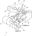
Fig. 1 is a perspective view showing a shift-by-wire system according to embodiment 1.
Fig. 2 is a schematic configuration diagram showing a shift-by-wire system according to embodiment 1.
Fig. 3 is a schematic view showing a stator and a rotor according to embodiment 1.
Fig. 4 is a circuit diagram showing the motor winding and the drive circuit according to embodiment 1.
Fig. 5 is a timing chart for explaining the motor drive control according to embodiment 1.
Fig. 6 is a diagram illustrating a conduction path in the feedback control according to embodiment 1.
Fig. 7 is a diagram illustrating an energization path in stop control by 2-phase energization in the reference example.
Fig. 8 is an explanatory diagram for explaining the current-carrying path during the stop control in embodiment 1.
Fig. 9 is a flowchart for explaining the motor drive control process according to embodiment 1.
Fig. 10 is a timing chart illustrating switching of the conduction phase in the stop control of embodiment 1.
Fig. 11 is a flowchart for explaining the motor drive control process according to embodiment 2.
Detailed Description
Hereinafter, a shift range control device according to the present invention will be described with reference to the drawings. In the following, in the embodiments, substantially the same structure is given the same reference numeral and description thereof is omitted.
(embodiment 1)
Fig. 1 to 10 show embodiment 1. As shown in fig. 1 and 2, a shift-by-wire system 1 as a shift range switching system includes a motor 10, a shift range switching mechanism 20, a parking lock mechanism 30, a shift range control device 40, and the like.
The motor 10 is rotated by being supplied with power from a battery 45 mounted on a vehicle not shown, and functions as a drive source of the shift range switching mechanism 20. The motor 10 of the present embodiment is a permanent magnet type DC brushless motor.
As shown in fig. 3, the motor 10 includes a stator 101, a rotor 105, and a motor winding 11 (see fig. 4). The motor winding 11 includes a U-phase coil 111, a V-phase coil 112, and a W-phase coil 113. A groove (slot)102 is formed in the stator 101. The number of grooves in this embodiment is 12. The motor winding 11 is wound in the groove 102. The rotor 105 has a permanent magnet, and rotates integrally with a motor shaft, not shown, by energization of the motor winding 11. The number of poles of the rotor 105 is 8. The number of grooves and the number of magnetic poles can be designed appropriately.
As shown in fig. 2, the encoder 13 as a motor rotation angle sensor detects the rotation position of the rotor 105. The encoder 13 is, for example, a magnetic rotary encoder, and is configured by a magnet that rotates integrally with the rotor, a hall IC for magnetic detection, and the like. The encoder 13 is a 3-phase encoder that outputs encoder signals, which are pulse signals of a phase, B phase, and C phase, at predetermined angles in synchronization with the rotation of the rotor.
The speed reducer 14 is provided between the motor shaft of the motor 10 and the output shaft 15, and reduces the rotation of the motor 10 and outputs the reduced rotation to the output shaft 15. Thereby, the rotation of the motor 10 is transmitted to the shift-position switching mechanism 20. An output shaft sensor 16 that detects the angle of the output shaft 15 is provided on the output shaft 15. The output shaft sensor 16 of the present embodiment is, for example, a potentiometer (potentiometer).
As shown in fig. 1, the shift range switching mechanism 20 includes a stopper plate 21, a stopper spring 25, and the like, and transmits the rotational driving force output from the reduction gear unit 14 to the manual valve 28 and the parking lock mechanism 30.
The stopper plate 21 is fixed to the output shaft 15 and driven by the motor 10. In the present embodiment, the direction in which the stopper plate 21 moves away from the base of the stopper spring 25 is a forward rotation direction, and the direction in which the stopper plate moves toward the base is a reverse rotation direction.
The stopper plate 21 is provided with a pin 24 protruding in parallel with the output shaft 15. The pin 24 is connected to a manual valve 28. The stopper plate 21 is driven by the motor 10, so that the manual valve 28 reciprocates in the axial direction. That is, the shift range switching mechanism 20 converts the rotational motion of the motor 10 into a linear motion and transmits the linear motion to the manual valve 28. The manual valve 28 is provided to the valve body 29. By the reciprocal movement of the manual valve 28 in the axial direction, a hydraulic pressure supply path to the hydraulic clutch, not shown, is switched, the engagement state of the hydraulic clutch is switched, and the shift range is changed.
Two recesses 22, 23 are provided on the stopper plate 21 on the stopper spring 25 side. In the present embodiment, the recess 22 is provided on the side closer to the base of the stopper spring 25, and the recess 23 is provided on the side farther away. In the present embodiment, the concave portion 22 corresponds to a non-P (notp) stage other than the P stage, and the concave portion 23 corresponds to the P stage.
The stopper spring 25 is an elastically deformable plate-like member, and a stopper roller 26 is provided at the tip. The stopper spring 25 biases the stopper roller 26 toward the rotation center side of the stopper plate 21. When a rotational force of a predetermined value or more acts on the stopper plate 21, the stopper spring 25 is elastically deformed, and the stopper roller 26 moves between the concave portions 22 and 23. The detent roller 26 is fitted into one of the recesses 22, 23, and the swing of the detent plate 21 is restricted, so that the axial position of the manual valve 28 and the state of the parking lock mechanism 30 are determined, and the shift position of the automatic transmission 5 is fixed. The stopper roller 26 is fitted into the recess 22 when the shift position is not the P range, and is fitted into the recess 23 when the shift position is the P range.
The parking lock mechanism 30 has a parking lever 31, a cone 32, a parking lock cylinder 33, a shaft 34, and a parking gear 35. The parking lever 31 is formed in a substantially L-shape, and one end 311 side is fixed to the stopper plate 21. A cone 32 is provided on the other end 312 side of the parking lever 31. The cone 32 is formed so as to be reduced in diameter toward the other end 312 side. If the stopper plate 21 swings in the reverse rotation direction, the cone 32 moves in the P direction.
The parking lock cylinder 33 is in contact with the conical surface of the cone 32 and is provided swingably about the shaft 34. A convex portion 331 engageable with the parking gear 35 is provided on the parking gear 35 side of the parking lock cylinder 33. When the detent plate 21 is rotated in the reverse rotation direction and the cone 32 is moved in the P direction, the parking lock cylinder 33 is pushed up and the projection 331 engages with the parking gear 35. On the other hand, if the detent plate 21 rotates in the normal rotation direction and the cone 32 moves in the non-P direction, the engagement between the convex portion 331 and the parking gear 35 is released.
The parking gear 35 is provided on an unillustrated axle and is provided to be capable of meshing with the convex portion 331 of the parking lock cylinder 33. If the parking gear 35 is engaged with the convex portion 331, the rotation of the axle is restricted. When the shift range is the non-P range, the parking gear 35 is not locked by the parking lock column 33, and the rotation of the axle is not hindered by the parking lock mechanism 30. When the shift position is the P range, the parking gear 35 is locked by the parking lock column 33, and the rotation of the axle is restricted.
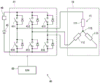
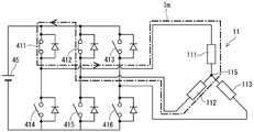
As shown in fig. 2 and 4, the shift position control device 40 includes a drive circuit 41, an ECU50, and the like. As shown in FIG. 4, the drive circuit 41 is a 3-phase inverter for converting the power supplied from the battery 45, and switching elements 411 to 416 are bridged. A relay 46 is provided between the battery 45 and the drive circuit 41.
One end of the U-phase coil 111 is connected to a connection point of the paired U-phase switching elements 411 and 414. One end of the V-phase coil 112 is connected to a connection point of the paired V- phase switching elements 412 and 415. One end of the W-phase coil 113 is connected to a connection point of the paired W- phase switching elements 413 and 416. The other ends of the coils 111-113 are connected by a connecting part 115. The switching elements 411 to 416 of the present embodiment are MOSFETs, but other elements such as IGBTs may be used. Hereinafter, the switching elements 411 to 413 connected to the high potential side are referred to as "upper arm elements" and the switching elements 414 to 416 connected to the low potential side are referred to as "lower arm elements", as appropriate.
As shown in fig. 2, the ECU50 is mainly composed of a microcomputer or the like, and includes therein a CPU, a ROM, a RAM, an I/O, a bus connecting these components, and the like, all of which are not shown. Each process in the ECU50 may be a software process performed by the CPU executing a program stored in advance in a physical memory device such as a ROM (i.e., a readable non-transitory tangible recording medium), or a hardware process performed by a dedicated electronic circuit.
The ECU50 controls the on/off operation of the switching elements 411 to 416 to control the driving of the motor 10 so that the driver's requested shift position input by an operation of a shift lever or the like, not shown, matches the shift position of the shift position switching mechanism 20. The ECU50 controls the driving of the speed-change hydraulic pressure control solenoid 6 based on the vehicle speed, the accelerator position, the driver's requested shift position, and the like. The gear shift stage is controlled by controlling the gear shift hydraulic pressure control solenoid 6. The number of the speed-changing hydraulic control solenoids 6 is set to correspond to the number of the speed-changing stages or the like. In the present embodiment, the 1 ECU50 controls the driving of the motor 10 and the solenoid 6, but a motor ECU for controlling the motor 10 may be separated from an AT-ECU for controlling the solenoid. Hereinafter, the drive control of the motor 10 will be mainly described.
The ECU50 includes an angle calculation unit 51 and a drive control unit 55. The angle calculation unit 51 counts the pulse edges of each phase of the encoder signal output from the encoder 13, and calculates an encoder count value θ en. The encoder count value θ en is a value corresponding to the rotational position of the motor 10, and corresponds to "motor angle".
The drive control unit 55 generates a drive signal relating to drive control of the motor 10 such that the encoder count value θ en falls within a control range Rc including a target count value θ cmd set in accordance with the requested shift range. The generated drive signal is output to the drive circuit 41. The drive of the motor 10 is controlled by switching the on/off of the switching elements 411 to 416 in accordance with a drive signal. In the present embodiment, the target count value θ cmd corresponds to a "target stop position".
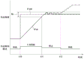
Fig. 5 is a timing chart illustrating drive control of the motor 10. In fig. 5, the common time axis is represented on the horizontal axis, the motor angle is represented on the upper stage, and the motor drive mode is represented on the lower stage. The feedback is appropriately denoted as "F/B" in the figure. The motor angle is represented as a count value of the encoder 13, a target count value θ cmd is represented by a one-dot chain line, and an encoder count value θ en is represented by a solid line. For the sake of explanation, the line shift is described as appropriate. Note that the time scale (time scale) and the like are appropriately changed and do not always coincide with the actual operation. Fig. 5 illustrates an example of a case where the shift range is switched from the P range to the non-P range.
At time t10, if the shift range is requested to be switched from P range to non-P range, the motor drive mode is switched from the standby mode to the feedback control mode. The target count value θ cmd is set, and the motor 10 is driven so that the encoder count value θ en becomes the target count value θ cmd.
At time t11, if the encoder count value θ en falls within the control range Rc that includes the target count value θ cmd (e.g., θ cmd ± 2 count), the motor drive mode is switched from the feedback control mode to the stop control mode.
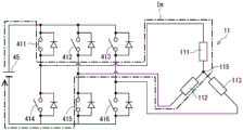
Fig. 6 shows an example of the energization state immediately before switching to the stop control. In fig. 6 to 8, a part of the structure of the relay 46 and the like is omitted, and the current carrying path is indicated by an arrow Im of a one-dot chain line. As shown in fig. 6, it is assumed that the energization pattern immediately before switching to the stop control is UV phase energization, the upper arm element 411 of the U phase is turned on, and the lower arm element 415 of the V phase is turned on and off at a set duty ratio.
Here, a reference example of performing 2-phase energization in the stop control will be described. When the 2-phase current is applied, for example, as shown in fig. 7, the upper arm element 411 of the U-phase and the lower arm element 415 of the V-phase are turned on. As shown in fig. 3, if the rotor 105 has a magnet, if 2-phase energization is performed, there is a possibility that the rotor 105 may continue to vibrate due to the action and reaction of the magnet between the rotor 105 and the stator 101 as shown by the two-dot chain line in fig. 5. If the energization is turned off at time t12 while the rotor 105 is vibrating, the rotor 105 rotates at the off timing, and in some cases, the output shaft 15 is pushed up and may be accidentally switched to a gear different from the target gear. Fig. 5 shows an example of overshoot (overshoot), but depending on the timing of the energization off, undershoot may occur.
Therefore, in the present embodiment, as shown in fig. 8, the upper arm elements 411 and 412 of the 2-phase (U-phase and V-phase in the example of fig. 8) are turned on, and the current flowing through the motor winding 11 is returned. At this time, current flows between the motor coil 11 and the drive circuit 41, and current from the battery 45 is not used. When a current is caused to flow back between the motor winding 11 and the drive circuit 41, the current is attenuated by the resistance of the electronic components constituting the return path, and the vibration of the rotor 105 is immediately smoothed as indicated by a solid line in fig. 5. After the rotation speed N of the rotor 105 has decreased to such an extent that overshoot or undershoot does not occur even when the energization is turned off, all the switching elements 411 to 416 are turned off, whereby the motor 10 can be stopped within the control range Rc.
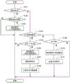
The motor drive control processing of the present embodiment will be described based on the flowchart of fig. 9. This process is executed by the ECU50 at a predetermined cycle (for example, 1[ ms ]). Hereinafter, the "step" of step S101 is omitted and simply denoted by the symbol "S". The same applies to the other steps.
In S101, the drive control unit 55 determines whether or not the motor drive mode is the standby mode. If it is determined that the mode is not the standby mode (S101: NO), the process proceeds to S104. If the mode is determined to be the standby mode (S101: YES), the process proceeds to S102.
In S102, drive control unit 55 determines whether or not the target shift range is switched. When it is determined that the target shift stage has not been switched (no in S102), the process in S103 is not performed, the standby mode is maintained, and the routine is ended. If it is determined that the target shift range has been switched (yes in S102), the process proceeds to S103, where the motor drive mode is switched to the feedback control mode.
In S104 to which a transition is made in the case where a negative determination is made in S101, the drive control portion 55 determines whether or not the motor drive mode is the feedback control mode. If it is determined that the mode is not the feedback control mode (no in S104), the process proceeds to S109. If it is determined that the motor drive mode is the feedback control mode (yes in S104), the process proceeds to S105.
In S105, the drive control unit 55 determines whether or not the encoder count value θ en matches the target count value θ cmd. Here, when the encoder count value θ en is within a predetermined range (for example, ± 2 counts) including the target count value θ cmd, it is assumed that the encoder count value θ en matches the target count value θ cmd. When it is determined that the encoder count value θ en does not coincide with the target count value θ cmd (no in S105), the feedback control mode is maintained without performing the processing in S106 and thereafter, and the routine is terminated. If it is determined that the encoder count value θ en matches the target count value θ cmd (yes in S105), the process proceeds to S106.
In S106, the drive control unit 55 switches the motor drive mode to the stop control mode. In S107, drive control unit 55 sets the power-on phase based on encoder count value θ en. In S108, the upper arm element of phase 2 determined in S107 is turned on. Thereby, the motor current flows back between the drive circuit 41 and the motor winding 11.
In S109 to which a negative determination is made in S104, that is, in a case where the motor drive mode is the stop control mode, the drive control unit 55 determines whether or not the motor rotation speed N is equal to or less than the rotation speed determination threshold Nth. The rotation speed determination threshold Nth is set according to the rotation speed to the extent that the rotor 105 can be stopped within the control range Rc when all the switching elements 411 to 416 are turned off. When it is determined that the motor rotation speed N is greater than the rotation speed determination threshold Nth (no in S109), the control mode is continued without performing the processing from S110 onward, and the routine is ended. When it is determined that the motor rotation speed N is equal to or less than the rotation speed determination threshold Nth (YES in S109), the operation proceeds to S110, the motor driving mode is switched to the standby mode, and all the switching elements 411 to 416 are turned off in S111.
The processing in S107 and S108 will be described with reference to fig. 10. Fig. 10 shows a motor drive mode, a motor angle, an encoder pattern, and a power-on pattern on the upper stage with the common time axis on the horizontal axis. In fig. 10, the description will be made assuming that the control is switched to the stop control when the encoder count value θ en reaches the target count value θ cmd.
In the present embodiment, the encoder pattern is set to 0 to 6 based on the encoder count value θ en. Then, the energization pattern is determined according to the set encoder pattern. The timing indicated by the hollow triangle is the execution timing of the motor drive control process of fig. 9. Further, every time the pulse edge of the encoder signal is detected, the operation of the encoder count value θ en in the angle operation unit 51 is interrupted.
At time t21 when the encoder count value θ en and the target count value θ cmd coincide with each other and become the first calculation timing, the motor drive control mode is switched from the feedback control mode to the stop control mode. Since the current pattern at this time is WV-phase current, the V-phase upper arm element 412 and the W-phase upper arm element 413 are turned on.
Further, if the encoder count value θ en changes at time t22, which is the next calculation timing, due to the vibration of the rotor 105, the encoder pattern and the energization pattern change. Since the energization pattern at this time is WU-phase energization, the upper arm element 411 of the U-phase and the upper arm element 413 of the W-phase are turned on. Further, since the energization pattern at time t23, which is the next operation timing, is WV-phase energization, the V-phase upper arm element 412 and the W-phase upper arm element 413 are turned on.
As described above, the shift position control device 40 of the present embodiment switches the shift position by controlling the driving of the motor 10 having the motor winding 11, and includes the drive circuit 41 and the ECU50 as a control unit.
The drive circuit 41 has switching elements 411 to 416 provided corresponding to the respective motor windings. The ECU50 drives the motor 10 by controlling the on/off operation of the switching elements 411 to 416, and stops the motor 10 at a target stop position corresponding to the target shift position. Specifically, the motor 10 is stopped so that the encoder count value θ en becomes a control range Rc including a target count value θ cmd as a target stop position.
The switching elements 411 to 413 connected to the high potential side are upper arm elements, and the switching elements 414 to 416 connected to the low potential side of the upper arm elements are lower arm elements. In the stop control for stopping the motor 10 at the target stop position, the ECU50 turns off all the lower arm elements, turns on a predetermined number of upper arm elements, and causes a current to flow back between the motor winding 11 and the drive circuit 41.
By circulating the current between the motor winding 11 and the drive circuit 41, the current is reduced, and the kinetic energy of the motor 10 is consumed, so that the motor 10 can be accurately stopped at the target stop position. Further, since the electric power of the battery 45 is not used in the stop control, the power consumption related to the shift position switching can be reduced.
During stop control, the ECU50 switches the upper arm element to be turned on in accordance with a signal from the encoder 13 that detects the rotation angle of the motor 10. This enables the motor 10 to be stopped more appropriately.
When the rotation speed N of the motor 10 is equal to or less than the rotation speed determination threshold Nth after the stop control is started, the ECU50 turns off all the switching elements 411 to 416. This can prevent overshoot and undershoot after the stop control is completed.
The motor winding 11 is a 3-phase winding, and both upper arm elements are turned on in the stop control. One ends of U-phase coil 111, V-phase coil 112, and W-phase coil 113, which are windings of the respective phases constituting motor winding 11, are connected by connection portion 115. This allows the current to flow back appropriately.
The motor 10 includes a stator 101 around which the motor wire 11 is wound, and a rotor 105 that rotates by energization of the motor wire 11. The rotor 105 has a magnet. Even when the rotor 105 has a magnet and the rotor 105 vibrates during stop control due to the influence of cogging torque, the current is returned during stop control, whereby vibration can be attenuated and the motor 10 can be appropriately stopped at a target stop position.
(embodiment 2)
Fig. 11 shows embodiment 2. The present embodiment is different from the above embodiments in the motor drive control processing, and therefore the description will be given mainly on this point. The motor drive control processing of the present embodiment will be described based on the flowchart of fig. 11. Fig. 11 differs from fig. 8 in that S109 is replaced with S119. When the drive mode is set to the stop control mode in S106, the time counting of the time after the start of the stop control is started.
In S119 to which a negative determination is made in S104, that is, in a case where the motor drive mode is the stop control mode, the drive control portion 55 determines whether or not the stop control duration has elapsed since the start of the stop control. If it is determined that the stop control duration has not elapsed (no in S119), the stop control mode is continued without performing the processing from S110 onward, and the present routine is ended. If it is determined that the stop control duration has elapsed (yes in S109), the process proceeds to S110. The stop control duration is set according to the time required to consume the motor current to such an extent that the rotor 105 can be stopped within the control range Rc when all the switching elements 411 to 416 are turned off.
In the present embodiment, when the stop control duration has elapsed after the start of the stop control, the ECU50 turns off all the switching elements 411 to 416. This can prevent overshoot and undershoot after the stop control is completed. Further, the same effects as those of the above embodiment are obtained.
(other embodiments)
In the above embodiment, in the stop control, the upper arm element of 2 phases is turned on. In other embodiments, the upper arm element of 3 phases may be turned on. In the above-described embodiment, the power-on phase is switched in accordance with the encoder count value in the stop control. In another embodiment, the stop control may be performed by continuing the on state of the element that was turned on at the start of the stop control until the end of the stop control without switching the conduction phase. The control method of the motor before the start of the stop control is not limited to the feedback control.
In other embodiments, the circuit configuration and the number of energized phases may be different from those in the above embodiments as long as the current can be circulated by the drive circuit and the motor winding. In the above embodiment, 1 set of motor windings and driving circuit is provided. In other embodiments, multiple sets of motor windings and drive circuits may be provided.
In the above embodiment, the motor rotation angle sensor that detects the rotation angle of the motor is a 3-phase encoder. In other embodiments, the motor rotation angle sensor may be a 2-phase encoder, and may be not limited to an encoder, but may be a resolver (resolver) or the like. In the above-described embodiment, a potentiometer is exemplified as the output shaft sensor. In other embodiments, the output shaft sensor may not be a potentiometer. The output shaft sensor may be omitted.
In the above embodiment, two recesses are provided in the stopper plate. In other embodiments, the number of the concave portions is not limited to two, and for example, the concave portions may be provided for each shift position. The shift range switching mechanism, the parking lock mechanism, and the like may be different from the above embodiment.
In the above embodiment, a speed reducer is provided between the motor shaft and the output shaft. The details of the speed reducer are not described in the above embodiments, and any configuration may be adopted, such as a configuration using a cycloid gear, a planetary gear, a spur gear that transmits torque from a speed reduction mechanism substantially coaxial with the motor shaft to the drive shaft, or a configuration using a combination of these. In other embodiments, the speed reducer between the motor shaft and the output shaft may be omitted, or a mechanism other than the speed reducer may be provided. As described above, the present invention is not limited to the above embodiments, and can be implemented in various forms without departing from the scope of the invention.
The control unit and the method thereof according to the present invention may be realized by a dedicated computer provided to constitute a processor and a memory, which are embodied by computer programs and programmed to execute one or more functions. Alternatively, the control unit and the method thereof according to the present invention may be realized by a dedicated computer provided with a processor constituted by one or more dedicated hardware logic circuits. Alternatively, the control unit and the method thereof according to the present invention may be realized by one or more special purpose computers each configured by a combination of a processor and a memory programmed to execute one or more functions and a processor configured by one or more hardware logic circuits. The computer program may be stored in a non-transportable tangible computer-readable medium as instructions to be executed by a computer.
The present invention has been described in terms of the above embodiments, but is not limited to the embodiments, and various modifications and equivalent variations are also included. In addition, various combinations and forms, and further, other combinations and forms including only one element, more than one element, or less than one element are also within the scope and spirit of the present invention.
Claims (7)
1. A shift range control device for switching a shift range by controlling driving of a motor (10) having a motor winding (11),
the disclosed device is provided with:
a drive circuit (41) having switching elements (411-416) provided corresponding to the respective motor windings; and
a control unit (50) for driving the motor by controlling the on/off operation of the switching element to stop the motor at a target stop position corresponding to a target shift position;
the switching elements (411-413) connected to the high potential side are used as upper arm elements, the switching elements (414-416) connected to the low potential side of the upper arm elements are used as lower arm elements,
the control unit turns off all the lower arm elements and turns on a predetermined number of the upper arm elements, and causes a current to flow back between the motor winding and the drive circuit in stop control for stopping the motor at the target stop position.
2. Shift position control device according to claim 1,
the control unit switches the upper arm element to be turned on in accordance with a signal from a motor rotation angle sensor (13) that detects the rotation angle of the motor during the stop control.
3. Shift position control device according to claim 1 or 2,
the control unit turns off all the switching elements when the rotation speed of the motor becomes equal to or less than a rotation speed determination threshold value after the stop control is started.
4. Shift position control device according to claim 1 or 2,
the control unit turns off all the switching elements when the stop control duration has elapsed after the start of the stop control.
5. The shift position control device according to any one of claims 1 to 4,
the motor winding is a 3-phase winding, and the two upper arm elements are turned on in the stop control.
6. The shift position control device according to any one of claims 1 to 5,
one ends of the windings (111-113) of each phase constituting the motor windings are connected by a connecting part (115).
7. The shift position control device according to any one of claims 1 to 6,
the motor comprises a stator (101) wound with the motor winding and a rotor (105) rotated by the energization of the motor winding;
the rotor has a magnet.
Applications Claiming Priority (3)
| Application Number | Priority Date | Filing Date | Title |
|---|---|---|---|
| JP2018158252A JP2020034013A (en) | 2018-08-27 | 2018-08-27 | Shift range control device |
| JP2018-158252 | 2018-08-27 | ||
| PCT/JP2019/032276 WO2020045146A1 (en) | 2018-08-27 | 2019-08-19 | Shift range control device |
Publications (1)
| Publication Number | Publication Date |
|---|---|
| CN112368933A true CN112368933A (en) | 2021-02-12 |
Family
ID=69643906
Family Applications (1)
| Application Number | Title | Priority Date | Filing Date |
|---|---|---|---|
| CN201980044537.9A Pending CN112368933A (en) | 2018-08-27 | 2019-08-19 | Shift gear control device |
Country Status (5)
| Country | Link |
|---|---|
| US (1) | US20210180690A1 (en) |
| JP (1) | JP2020034013A (en) |
| CN (1) | CN112368933A (en) |
| DE (1) | DE112019004286T5 (en) |
| WO (1) | WO2020045146A1 (en) |
Families Citing this family (1)
| Publication number | Priority date | Publication date | Assignee | Title |
|---|---|---|---|---|
| KR102263101B1 (en) * | 2019-12-03 | 2021-06-09 | 주식회사 현대케피코 | Aparatus and method for learning motor position of electric shift-by-wire system |
Citations (9)
| Publication number | Priority date | Publication date | Assignee | Title |
|---|---|---|---|---|
| JPH05252769A (en) * | 1992-03-06 | 1993-09-28 | Brother Ind Ltd | Motor driver |
| JPH09500519A (en) * | 1993-11-12 | 1997-01-14 | エクサバイト コーポレイション | Power-off motor deceleration control system |
| JP2004129451A (en) * | 2002-10-07 | 2004-04-22 | Denso Corp | Motor controller |
| CN103296942A (en) * | 2012-02-28 | 2013-09-11 | 发那科株式会社 | Motor drive apparatus equipped with dynamic braking control unit |
| US20150222211A1 (en) * | 2014-02-04 | 2015-08-06 | Mitsubishi Electric Corporation | Shift range switching apparatus |
| JP2017184338A (en) * | 2016-03-28 | 2017-10-05 | パナソニックIpマネジメント株式会社 | Vehicle control device, vehicle control method, and vehicle control program |
| CN107360736A (en) * | 2015-02-25 | 2017-11-17 | 株式会社电装 | Controller for motor |
| WO2018047916A1 (en) * | 2016-09-09 | 2018-03-15 | 株式会社デンソー | Shift range control device |
| US20180236874A1 (en) * | 2015-02-25 | 2018-08-23 | Honda Motor Co., Ltd. | Electric power system |
Family Cites Families (3)
| Publication number | Priority date | Publication date | Assignee | Title |
|---|---|---|---|---|
| JP3910138B2 (en) * | 2001-12-05 | 2007-04-25 | 松下電器産業株式会社 | Motor driving apparatus and motor driving method |
| JP6459439B2 (en) * | 2014-11-27 | 2019-01-30 | コニカミノルタ株式会社 | Sheet conveying apparatus, image forming apparatus, and image reading apparatus |
| JP6536465B2 (en) * | 2016-04-26 | 2019-07-03 | 株式会社デンソー | Shift range control device |
-
2018
- 2018-08-27 JP JP2018158252A patent/JP2020034013A/en active Pending
-
2019
- 2019-08-19 CN CN201980044537.9A patent/CN112368933A/en active Pending
- 2019-08-19 WO PCT/JP2019/032276 patent/WO2020045146A1/en active Application Filing
- 2019-08-19 DE DE112019004286.6T patent/DE112019004286T5/en active Pending
-
2021
- 2021-02-25 US US17/184,779 patent/US20210180690A1/en not_active Abandoned
Patent Citations (9)
| Publication number | Priority date | Publication date | Assignee | Title |
|---|---|---|---|---|
| JPH05252769A (en) * | 1992-03-06 | 1993-09-28 | Brother Ind Ltd | Motor driver |
| JPH09500519A (en) * | 1993-11-12 | 1997-01-14 | エクサバイト コーポレイション | Power-off motor deceleration control system |
| JP2004129451A (en) * | 2002-10-07 | 2004-04-22 | Denso Corp | Motor controller |
| CN103296942A (en) * | 2012-02-28 | 2013-09-11 | 发那科株式会社 | Motor drive apparatus equipped with dynamic braking control unit |
| US20150222211A1 (en) * | 2014-02-04 | 2015-08-06 | Mitsubishi Electric Corporation | Shift range switching apparatus |
| CN107360736A (en) * | 2015-02-25 | 2017-11-17 | 株式会社电装 | Controller for motor |
| US20180236874A1 (en) * | 2015-02-25 | 2018-08-23 | Honda Motor Co., Ltd. | Electric power system |
| JP2017184338A (en) * | 2016-03-28 | 2017-10-05 | パナソニックIpマネジメント株式会社 | Vehicle control device, vehicle control method, and vehicle control program |
| WO2018047916A1 (en) * | 2016-09-09 | 2018-03-15 | 株式会社デンソー | Shift range control device |
Also Published As
| Publication number | Publication date |
|---|---|
| JP2020034013A (en) | 2020-03-05 |
| US20210180690A1 (en) | 2021-06-17 |
| DE112019004286T5 (en) | 2021-05-20 |
| WO2020045146A1 (en) | 2020-03-05 |
Similar Documents
| Publication | Publication Date | Title |
|---|---|---|
| CN110337780B (en) | Shift gear control device | |
| CN109075728B (en) | Shift gear control device | |
| CN109312851B (en) | Gear shifting and shifting device | |
| CN110325769B (en) | Shift gear control device | |
| US10844952B2 (en) | Shift range control apparatus | |
| CN109073073B (en) | Shift gear control device | |
| JP6658416B2 (en) | Shift range control device | |
| CN109690149B (en) | Shift gear control device | |
| US11655894B2 (en) | Shift range control device | |
| CN111512074B (en) | Shift gear control device | |
| US11448316B2 (en) | Shift range control apparatus | |
| CN111886427B (en) | Shift gear control device | |
| CN111095781A (en) | Shift gear control device | |
| CN112368933A (en) | Shift gear control device | |
| CN113039380B (en) | Shift gear control device | |
| US11828362B2 (en) | Shift range control device | |
| US11894792B2 (en) | Motor control device | |
| US11316464B2 (en) | Shift range control device | |
| US20210356040A1 (en) | Shift range control device | |
| US20220190750A1 (en) | Motor control device | |
| JP2019033620A (en) | Motor control device | |
| JP2021166426A (en) | Motor controller |
Legal Events
| Date | Code | Title | Description |
|---|---|---|---|
| PB01 | Publication | ||
| PB01 | Publication | ||
| SE01 | Entry into force of request for substantive examination | ||
| SE01 | Entry into force of request for substantive examination |