EP3061934A1 - Scr system, scr sensor, and level sensor - Google Patents
Scr system, scr sensor, and level sensor Download PDFInfo
- Publication number
- EP3061934A1 EP3061934A1 EP14855819.0A EP14855819A EP3061934A1 EP 3061934 A1 EP3061934 A1 EP 3061934A1 EP 14855819 A EP14855819 A EP 14855819A EP 3061934 A1 EP3061934 A1 EP 3061934A1
- Authority
- EP
- European Patent Office
- Prior art keywords
- urea solution
- inclination
- sensor
- float
- level
- Prior art date
- Legal status (The legal status is an assumption and is not a legal conclusion. Google has not performed a legal analysis and makes no representation as to the accuracy of the status listed.)
- Withdrawn
Links
Images



Classifications
-
- F—MECHANICAL ENGINEERING; LIGHTING; HEATING; WEAPONS; BLASTING
- F01—MACHINES OR ENGINES IN GENERAL; ENGINE PLANTS IN GENERAL; STEAM ENGINES
- F01N—GAS-FLOW SILENCERS OR EXHAUST APPARATUS FOR MACHINES OR ENGINES IN GENERAL; GAS-FLOW SILENCERS OR EXHAUST APPARATUS FOR INTERNAL-COMBUSTION ENGINES
- F01N3/00—Exhaust or silencing apparatus having means for purifying, rendering innocuous, or otherwise treating exhaust
- F01N3/08—Exhaust or silencing apparatus having means for purifying, rendering innocuous, or otherwise treating exhaust for rendering innocuous
- F01N3/10—Exhaust or silencing apparatus having means for purifying, rendering innocuous, or otherwise treating exhaust for rendering innocuous by thermal or catalytic conversion of noxious components of exhaust
- F01N3/18—Exhaust or silencing apparatus having means for purifying, rendering innocuous, or otherwise treating exhaust for rendering innocuous by thermal or catalytic conversion of noxious components of exhaust characterised by methods of operation; Control
- F01N3/20—Exhaust or silencing apparatus having means for purifying, rendering innocuous, or otherwise treating exhaust for rendering innocuous by thermal or catalytic conversion of noxious components of exhaust characterised by methods of operation; Control specially adapted for catalytic conversion
- F01N3/206—Adding periodically or continuously substances to exhaust gases for promoting purification, e.g. catalytic material in liquid form, NOx reducing agents
- F01N3/208—Control of selective catalytic reduction [SCR], e.g. by adjusting the dosing of reducing agent
-
- F—MECHANICAL ENGINEERING; LIGHTING; HEATING; WEAPONS; BLASTING
- F01—MACHINES OR ENGINES IN GENERAL; ENGINE PLANTS IN GENERAL; STEAM ENGINES
- F01N—GAS-FLOW SILENCERS OR EXHAUST APPARATUS FOR MACHINES OR ENGINES IN GENERAL; GAS-FLOW SILENCERS OR EXHAUST APPARATUS FOR INTERNAL-COMBUSTION ENGINES
- F01N11/00—Monitoring or diagnostic devices for exhaust-gas treatment apparatus
-
- F—MECHANICAL ENGINEERING; LIGHTING; HEATING; WEAPONS; BLASTING
- F01—MACHINES OR ENGINES IN GENERAL; ENGINE PLANTS IN GENERAL; STEAM ENGINES
- F01N—GAS-FLOW SILENCERS OR EXHAUST APPARATUS FOR MACHINES OR ENGINES IN GENERAL; GAS-FLOW SILENCERS OR EXHAUST APPARATUS FOR INTERNAL-COMBUSTION ENGINES
- F01N3/00—Exhaust or silencing apparatus having means for purifying, rendering innocuous, or otherwise treating exhaust
- F01N3/08—Exhaust or silencing apparatus having means for purifying, rendering innocuous, or otherwise treating exhaust for rendering innocuous
- F01N3/10—Exhaust or silencing apparatus having means for purifying, rendering innocuous, or otherwise treating exhaust for rendering innocuous by thermal or catalytic conversion of noxious components of exhaust
- F01N3/18—Exhaust or silencing apparatus having means for purifying, rendering innocuous, or otherwise treating exhaust for rendering innocuous by thermal or catalytic conversion of noxious components of exhaust characterised by methods of operation; Control
- F01N3/20—Exhaust or silencing apparatus having means for purifying, rendering innocuous, or otherwise treating exhaust for rendering innocuous by thermal or catalytic conversion of noxious components of exhaust characterised by methods of operation; Control specially adapted for catalytic conversion
- F01N3/206—Adding periodically or continuously substances to exhaust gases for promoting purification, e.g. catalytic material in liquid form, NOx reducing agents
- F01N3/2066—Selective catalytic reduction [SCR]
-
- F—MECHANICAL ENGINEERING; LIGHTING; HEATING; WEAPONS; BLASTING
- F01—MACHINES OR ENGINES IN GENERAL; ENGINE PLANTS IN GENERAL; STEAM ENGINES
- F01N—GAS-FLOW SILENCERS OR EXHAUST APPARATUS FOR MACHINES OR ENGINES IN GENERAL; GAS-FLOW SILENCERS OR EXHAUST APPARATUS FOR INTERNAL-COMBUSTION ENGINES
- F01N9/00—Electrical control of exhaust gas treating apparatus
-
- F—MECHANICAL ENGINEERING; LIGHTING; HEATING; WEAPONS; BLASTING
- F01—MACHINES OR ENGINES IN GENERAL; ENGINE PLANTS IN GENERAL; STEAM ENGINES
- F01N—GAS-FLOW SILENCERS OR EXHAUST APPARATUS FOR MACHINES OR ENGINES IN GENERAL; GAS-FLOW SILENCERS OR EXHAUST APPARATUS FOR INTERNAL-COMBUSTION ENGINES
- F01N2550/00—Monitoring or diagnosing the deterioration of exhaust systems
- F01N2550/05—Systems for adding substances into exhaust
-
- F—MECHANICAL ENGINEERING; LIGHTING; HEATING; WEAPONS; BLASTING
- F01—MACHINES OR ENGINES IN GENERAL; ENGINE PLANTS IN GENERAL; STEAM ENGINES
- F01N—GAS-FLOW SILENCERS OR EXHAUST APPARATUS FOR MACHINES OR ENGINES IN GENERAL; GAS-FLOW SILENCERS OR EXHAUST APPARATUS FOR INTERNAL-COMBUSTION ENGINES
- F01N2610/00—Adding substances to exhaust gases
- F01N2610/02—Adding substances to exhaust gases the substance being ammonia or urea
-
- F—MECHANICAL ENGINEERING; LIGHTING; HEATING; WEAPONS; BLASTING
- F01—MACHINES OR ENGINES IN GENERAL; ENGINE PLANTS IN GENERAL; STEAM ENGINES
- F01N—GAS-FLOW SILENCERS OR EXHAUST APPARATUS FOR MACHINES OR ENGINES IN GENERAL; GAS-FLOW SILENCERS OR EXHAUST APPARATUS FOR INTERNAL-COMBUSTION ENGINES
- F01N2610/00—Adding substances to exhaust gases
- F01N2610/14—Arrangements for the supply of substances, e.g. conduits
- F01N2610/1406—Storage means for substances, e.g. tanks or reservoirs
-
- F—MECHANICAL ENGINEERING; LIGHTING; HEATING; WEAPONS; BLASTING
- F01—MACHINES OR ENGINES IN GENERAL; ENGINE PLANTS IN GENERAL; STEAM ENGINES
- F01N—GAS-FLOW SILENCERS OR EXHAUST APPARATUS FOR MACHINES OR ENGINES IN GENERAL; GAS-FLOW SILENCERS OR EXHAUST APPARATUS FOR INTERNAL-COMBUSTION ENGINES
- F01N2610/00—Adding substances to exhaust gases
- F01N2610/14—Arrangements for the supply of substances, e.g. conduits
- F01N2610/1453—Sprayers or atomisers; Arrangement thereof in the exhaust apparatus
- F01N2610/146—Control thereof, e.g. control of injectors or injection valves
-
- F—MECHANICAL ENGINEERING; LIGHTING; HEATING; WEAPONS; BLASTING
- F01—MACHINES OR ENGINES IN GENERAL; ENGINE PLANTS IN GENERAL; STEAM ENGINES
- F01N—GAS-FLOW SILENCERS OR EXHAUST APPARATUS FOR MACHINES OR ENGINES IN GENERAL; GAS-FLOW SILENCERS OR EXHAUST APPARATUS FOR INTERNAL-COMBUSTION ENGINES
- F01N2610/00—Adding substances to exhaust gases
- F01N2610/14—Arrangements for the supply of substances, e.g. conduits
- F01N2610/148—Arrangement of sensors
-
- F—MECHANICAL ENGINEERING; LIGHTING; HEATING; WEAPONS; BLASTING
- F01—MACHINES OR ENGINES IN GENERAL; ENGINE PLANTS IN GENERAL; STEAM ENGINES
- F01N—GAS-FLOW SILENCERS OR EXHAUST APPARATUS FOR MACHINES OR ENGINES IN GENERAL; GAS-FLOW SILENCERS OR EXHAUST APPARATUS FOR INTERNAL-COMBUSTION ENGINES
- F01N2900/00—Details of electrical control or of the monitoring of the exhaust gas treating apparatus
- F01N2900/04—Methods of control or diagnosing
- F01N2900/0416—Methods of control or diagnosing using the state of a sensor, e.g. of an exhaust gas sensor
-
- F—MECHANICAL ENGINEERING; LIGHTING; HEATING; WEAPONS; BLASTING
- F01—MACHINES OR ENGINES IN GENERAL; ENGINE PLANTS IN GENERAL; STEAM ENGINES
- F01N—GAS-FLOW SILENCERS OR EXHAUST APPARATUS FOR MACHINES OR ENGINES IN GENERAL; GAS-FLOW SILENCERS OR EXHAUST APPARATUS FOR INTERNAL-COMBUSTION ENGINES
- F01N2900/00—Details of electrical control or of the monitoring of the exhaust gas treating apparatus
- F01N2900/06—Parameters used for exhaust control or diagnosing
- F01N2900/10—Parameters used for exhaust control or diagnosing said parameters being related to the vehicle or its components
-
- F—MECHANICAL ENGINEERING; LIGHTING; HEATING; WEAPONS; BLASTING
- F01—MACHINES OR ENGINES IN GENERAL; ENGINE PLANTS IN GENERAL; STEAM ENGINES
- F01N—GAS-FLOW SILENCERS OR EXHAUST APPARATUS FOR MACHINES OR ENGINES IN GENERAL; GAS-FLOW SILENCERS OR EXHAUST APPARATUS FOR INTERNAL-COMBUSTION ENGINES
- F01N2900/00—Details of electrical control or of the monitoring of the exhaust gas treating apparatus
- F01N2900/06—Parameters used for exhaust control or diagnosing
- F01N2900/18—Parameters used for exhaust control or diagnosing said parameters being related to the system for adding a substance into the exhaust
- F01N2900/1806—Properties of reducing agent or dosing system
- F01N2900/1814—Tank level
-
- Y—GENERAL TAGGING OF NEW TECHNOLOGICAL DEVELOPMENTS; GENERAL TAGGING OF CROSS-SECTIONAL TECHNOLOGIES SPANNING OVER SEVERAL SECTIONS OF THE IPC; TECHNICAL SUBJECTS COVERED BY FORMER USPC CROSS-REFERENCE ART COLLECTIONS [XRACs] AND DIGESTS
- Y02—TECHNOLOGIES OR APPLICATIONS FOR MITIGATION OR ADAPTATION AGAINST CLIMATE CHANGE
- Y02T—CLIMATE CHANGE MITIGATION TECHNOLOGIES RELATED TO TRANSPORTATION
- Y02T10/00—Road transport of goods or passengers
- Y02T10/10—Internal combustion engine [ICE] based vehicles
- Y02T10/12—Improving ICE efficiencies
-
- Y—GENERAL TAGGING OF NEW TECHNOLOGICAL DEVELOPMENTS; GENERAL TAGGING OF CROSS-SECTIONAL TECHNOLOGIES SPANNING OVER SEVERAL SECTIONS OF THE IPC; TECHNICAL SUBJECTS COVERED BY FORMER USPC CROSS-REFERENCE ART COLLECTIONS [XRACs] AND DIGESTS
- Y02—TECHNOLOGIES OR APPLICATIONS FOR MITIGATION OR ADAPTATION AGAINST CLIMATE CHANGE
- Y02T—CLIMATE CHANGE MITIGATION TECHNOLOGIES RELATED TO TRANSPORTATION
- Y02T10/00—Road transport of goods or passengers
- Y02T10/10—Internal combustion engine [ICE] based vehicles
- Y02T10/40—Engine management systems
Definitions
- the present invention relates to an SCR system, an SCR sensor, and a level sensor.
- a selective catalytic reduction (SCR) system that includes an SCR device is developed as an exhaust gas purification system for purifying NOx contained in exhaust gas of a diesel engine.
- a urea solution stored in a urea solution tank is supplied to an upstream side of the SCR device in an exhaust gas passage to generate ammonia, and NOx is reduced by this ammonia in the SCR device for purification of the exhaust gas.
- the SCR system includes an SCR sensor that has a float urea solution level sensor provided in the urea solution tank.
- the float urea solution level sensor includes a float that follows the liquid surface of the urea solution in the urea solution tank, and a detecting unit that detects the position of the float to detect the level of the liquid surface of the urea solution stored in the urea solution tank.
- the SCR system can detect a remaining amount of the urea solution.
- the liquid surface of the urea solution is not stable while a vehicle is running. Therefore, the SCR system is configured to detect the level of the liquid surface of the urea solution while the vehicle is not running (when the key switch is turned on or when the key switch is turned off) in order to accurately measure the level of the liquid surface of the urea solution.
- the urea solution tank When the vehicle is inclined (e.g., when the vehicle is parked partially on the sidewalk or the like), however, the urea solution tank is inclined relative to the horizontal plane. This may result in a problem in that the level of the liquid surface of the urea solution to be detected by the level sensor may not be detected accurately.
- the level of the liquid surface of the urea solution is also used, for example, to make a determination as to a consumption amount abnormality by comparing an instructed injection amount of the urea solution to an actually injected amount of the urea solution.
- various problems may arise when the level of the liquid surface of the urea solution cannot be detected accurately.
- an object of the present invention is to provide an SCR system, an SCR sensor, and a level sensor that solve the above-described problems and can detect the level of the liquid surface accurately even when a tank is inclined.
- the present invention has been made to achieve the above-mentioned object, and an aspect of the present invention provides an SCR system that includes a selective catalytic reduction device provided on an exhaust pipe of an engine, a urea solution tank configured to store (reserve) a urea solution, a float urea solution level sensor provided in the urea solution tank, and including a float configured to follow a liquid surface of the urea solution in the urea solution tank and a detecting unit configured to detect a position of the float to detect a level of the liquid surface of the urea solution stored in the urea solution tank, a dosing valve provided on the exhaust pipe upstream of the selective catalytic reduction device and configured to inject the urea solution, and a urea solution injection controlling unit configured to control an injection amount of the urea solution injected through the dosing valve in accordance with an amount of NOx emitted from the engine.
- a selective catalytic reduction device provided on an exhaust pipe of an engine
- the SCR system also includes an inclination sensor configured to detect an angle of inclination of the urea solution tank relative to a horizontal plane, and an inclination correcting unit configured to correct the level of the liquid surface of the urea solution, which is detected by the detecting unit on the basis of the position of the float, with the angle of inclination detected by the inclination sensor.
- the SCR system may further include an inclination abnormality determining unit configured to determine that inclination is abnormal when the angle of inclination detected by the inclination sensor is greater than a preset threshold angle.
- the SCR system may further include a cumulative instructed injection amount calculating unit configured to obtain a cumulative instructed injection amount, which is a cumulative value of instructed injection amounts of the urea solution instructed by the urea solution injection controlling unit.
- the SCR system may further include an actual injection amount calculating unit configured to obtain an actually injected amount of the urea solution on the basis of the level of the liquid surface of the urea solution corrected by the inclination correcting unit.
- the SCR system may further include a consumption amount abnormality determining unit configured to determine that a consumption amount is abnormal when a deviation of the actually injected amount from the cumulative instructed injection amount is greater than a predetermined value.
- an SCR sensor that includes a float urea solution level sensor provided in a urea solution tank that stores a urea solution.
- the urea solution is used to purify exhaust gas of an engine.
- the urea solution level sensor has a float configured to follow a liquid surface of the urea solution in the urea solution tank, and a detecting unit configured to detect a position of the float to detect a level of the liquid surface of the urea solution stored in the urea solution.
- the SCR sensor also include an inclination sensor configured to detect an angle of inclination of the urea solution tank relative to a horizontal plane, and an inclination correcting unit configured to correct the level of the liquid surface of the urea solution, which is detected by the detecting unit on the basis of the position of the float, with the angle of inclination detected by the inclination sensor.
- Still another aspect of the present invention provides a float level sensor that includes a float provided in a tank.
- the tank is used to store a liquid.
- the float is configured to follow a liquid surface of the liquid in the tank.
- the float level sensor also include a detecting unit configured to detect a position of the float to detect a level of the liquid surface of the liquid stored in the tank.
- the float level sensor also includes an inclination sensor configured to detect an angle of inclination of the tank relative to a horizontal plane, and an inclination correcting unit configured to correct the level of the liquid surface of the liquid, which is detected by the detecting unit on the basis of the position of the float, with the angle of inclination detected by the inclination sensor.
- the present invention provides an SCR system, an SCR sensor, and a level sensor that can detect the level of the liquid surface accurately even when a tank is inclined.
- Figs. 1(a) and 1(b) are schematic configuration diagrams of an SCR system according to an embodiment of the present embodiment.
- an SCR system 1 primarily includes an SCR device 3 provided on an exhaust pipe 2 of an engine (not illustrated), a urea solution tank 4 for storing a urea solution, a dosing valve (urea solution injection device) 5 that is provided on the exhaust pipe 2 upstream of the SCR device 3 to inject the urea solution, a supply module 6 that supplies the urea solution to the dosing valve 5 from the urea solution tank 4, and a dosing control unit (DCU) 7 that controls the dosing valve 5, the supply module 6, and relevant components.
- SCR device 3 provided on an exhaust pipe 2 of an engine (not illustrated)
- a urea solution tank 4 for storing a urea solution
- a dosing valve (urea solution injection device) 5 that is provided on the exhaust pipe 2 upstream of the SCR device 3 to inject the urea solution
- a supply module 6 that supplies the urea solution to the dosing valve 5 from the urea solution tank 4
- the dosing valve 5 has a structure in which an injection port is provided in a cylinder filled with a high-pressure urea solution and a valve body for closing the injection port is attached to a plunger. As electricity is passed to a coil, the plunger is lifted to move the valve body away from the injection port, and thus the urea solution is injected. When the passing of electricity to the coil is stopped, the plunger is pulled downward by the spring force thereinside, and the valve body closes the injection port. Thus, the injection of the urea solution is stopped.
- An exhaust gas temperature sensor 8 for measuring the temperature of exhaust gas at an inlet of the SCR device 3 is provided on the exhaust pipe 2 upstream of the SCR device 3, and an output signal line of the exhaust gas temperature sensor 8 is connected to the DCU 7.
- An upstream NOx sensor 9 for detecting the NOx concentration at the upstream side of the SCR device 3 is provided on the exhaust pipe 2 upstream of the SCR device 3.
- a downstream NOx sensor 10 for detecting the NOx concentration at the downstream side of the SCR device 3 is provided on the exhaust pipe 2 downstream of the SCR device 3.
- NOx sensor modules 11 and 12 for controlling the NOx sensors 9 and 10, respectively, are connected to the NOx sensors 9 and 10, and the NOx sensor modules 11 and 12 are connected to the DCU 7 via a controller area network (CAN).
- CAN controller area network
- the DCU 7 is connected to a key switch (ignition switch) 13 and a battery 14.
- the DCU 7 is also connected, via the CAN, to an engine control module (ECM) 15 that controls the engine.
- ECM engine control module
- the supply module 6 includes an SM pump 16 for pressurizing and feeding the urea solution, an SM temperature sensor 17 for measuring the temperature of the supply module 6, a urea solution pressure sensor 18 for measuring the pressure of the urea solution in the supply module 6 (i.e., the pressure at the discharge side of the SM pump 16), and a reverting valve 19 for switching between supplying the urea solution from the urea solution tank 4 to the dosing valve 5 and returning the urea solution from the dosing valve to the urea solution tank 4.
- Output signal lines of the SM temperature sensor 17 and the urea solution pressure sensor 18 are connected to the DCU 7, and input signal lines of the SM pump 16 and the reverting valve 19 are connected to the DCU 7.
- the supply module 6 causes the SM pump 16 to suck up the urea solution from the urea solution tank 4 through a liquid-feed line (suction line) 20, supply the urea solution to the dosing valve 5 via a pressure-feed line (pressure line) 21, and return any excess urea solution to the urea solution tank 4 via a recovery line (back line) 22.
- a filter 23 is disposed in the pressure-feed line 21.
- a cooling water line 28 for circulating cooling water to cool the engine is connected to the urea solution tank 4 and the supply module 6.
- the cooling water line 28 passes through the urea solution tank 4, in which heat is exchanged between the cooling water and the urea solution.
- the cooling water line 28 also passes through the supply module 6, in which heat is exchanged between the cooling water and the supply module 6.
- a tank heater valve 29 is disposed on the cooling water line 28, which passes through the urea solution tank 4 and the supply module 6, for switching between introducing and not introducing the cooling water into the urea solution tank 4 and the supply module 6.
- An input signal line of the tank heater valve 29 is connected to the DCU 7. Signals may be sent between the DCU 7 and other members via signal lines or via the CAN.
- the cooling water line 28 is connected to the dosing valve 5 as well.
- the cooling water is supplied to the dosing valve 5 regardless of whether the tank heater valve 29 is open or closed.
- the DCU 7 includes a urea solution injection controlling unit 30 that controls an amount of urea solution to be injected through the dosing valve 5 in accordance with an amount of NOx emitted from the engine.
- the urea solution injection controlling unit 30 estimates the amount of NOx contained in the exhaust gas on the basis of engine parameters obtained from the ECM 15 and the temperature of the exhaust gas obtained from the exhaust gas temperature sensor 8, and determines the amount of urea solution to be injected through the dosing valve 5 on the basis of the estimated amount of NOx.
- the urea solution injection controlling unit 30 controls the dosing valve 5 on the basis of the value detected by the upstream NOx sensor 9 to adjust the amount of the urea solution to be injected through the dosing valve 5.
- the urea solution tank 4 has an SCR sensor 24 attached thereto.
- the SCR sensor 24 includes a urea solution level sensor (hereinafter simply referred to as "level sensor”) 25 for measuring the level of the liquid surface (level) of the urea solution in the urea solution tank 4, a temperature sensor 26 for measuring the temperature of the urea solution in the urea solution tank 4, and a quality sensor 27 for measuring the quality of the urea solution in the urea solution tank 4.
- level sensor urea solution level sensor
- the quality sensor 27 detects, for example, the concentration of the urea solution and/or whether a heterogeneous mixture is mixed in the urea solution on the basis of the propagation speed of an ultrasonic wave or the electric conductivity, and determines the quality of the urea solution in the urea solution tank 4.
- the level sensor 25 is a float level sensor that includes a float 31 and a detecting unit 32.
- the float 31 is configured to follow the liquid surface of the urea solution in the urea solution tank 4.
- the detecting unit 32 is configured to detect the position of the float 31 to detect the level of the liquid surface of the urea solution stored in the urea solution tank 4.
- the float 31 is formed into a hollow cylindrical shape and has magnets.
- the detecting unit 32 includes a pipe to be disposed inside the hollow portion of the float 31 and reed switches provided along the longitudinal direction of the pipe at predetermined intervals. The contacts of the reed switches are closed by the magnets provided on the float 31. Detecting a reed switch whose contact is closed allows the position (height-wise position) of the float 31 to be detected. It should be noted that the configuration of the detecting unit 32 is not limited to the above-described configuration.
- the DCU 7 includes a urea solution level detecting unit 33 that obtains the level of the liquid surface of the urea solution stored in the urea solution tank 4 on the basis of a signal from the detecting unit 32.
- the DCU 7 also includes a cumulative instructed injection amount calculating unit 34 that obtains a cumulative amount of instructed injection, which is a cumulative value of the instructed injection amounts of the urea solution instructed by the urea solution injection controlling unit 30.
- the DCU 7 also includes an actual injection amount calculating unit 35 that obtains an actually injected amount of the urea solution on the basis of the level of the liquid surface of the urea solution.
- the DCU 7 also includes a consumption amount abnormality determining unit 36 that determines that the consumption amount is abnormal when the deviation of the actually injected amount from the cumulative instructed injection amount is greater than a predetermined value.
- the consumption amount abnormality determining unit 36 is configured to determine that the consumption amount is abnormal when a cumulative instructed injection amount P calculated by the cumulative instructed injection amount calculating unit 34 has reached or exceeded a preset determination amount Pth.
- the SCR system 1 of this embodiment also includes an inclination sensor 37 for detecting an angle of inclination of the urea solution tank 4 relative to the horizontal plane, and an inclination correcting unit 38 that corrects the level of the liquid surface of the urea solution, which is detected by the detecting unit 32 on the basis of the position of the float 31, in accordance with the angle of inclination detected by the inclination sensor 37.
- the level sensor 25 is disposed at a position offset from the center position of the urea solution tank 4 as viewed from the above.
- the inclination sensor 37 is configured to detect the angle of inclination relative to the horizontal plane in the direction in which the level sensor 25 is offset, i.e., in the direction extending from the center position of the urea tank 4 to the center position of the level sensor 25 as viewed from the above.
- the inclination sensor 37 is disposed on the upper portion of the urea solution tank 4. It should be noted that the position at which the inclination sensor 37 is provided is not limited thereto.
- the inclination sensor 37 may be provided, for example, on another member that inclines along with the urea solution tank 4.
- the level sensor 25 is disposed at a position C1 that is offset from the center position C of the urea solution tank 4. In this arrangement, the accurate level of the liquid surface cannot be detected when a vehicle 40 is inclined since the urea solution tank 4 is inclined relative to the horizontal plane.
- a level S A of the liquid surface which is higher than the level held when the urea solution tank 4 is disposed horizontally, is detected when the urea solution tank 4 is inclined in the counterclockwise direction in the drawing such that the liquid surface lies along the position A.
- a level S B of the liquid surface which is lower than the level held when the urea solution tank 4 is disposed horizontally, is detected when the urea solution tank 4 is inclined in the clockwise direction in the drawing such that the liquid surface lies along the position B.
- the error of the level of the liquid surface when the urea solution tank 4 is inclined relative to the level of the liquid surface when the urea solution tank 4 is disposed horizontally varies with an angle K of inclination. Therefore, in this embodiment, the angle K of inclination relative to the horizontal plane in the direction in which the level sensor 25 is offset from the center position C of the urea solution tank 4 is detected by the inclination sensor 37, and the level of the liquid surface when the urea solution tank 4 is inclined is corrected in accordance with the detected angle K of inclination. Thus, the level of the liquid surface when the urea solution tank 4 is disposed horizontally is estimated.
- the corrected level S' of the liquid surface (i.e., the level of the liquid surface when the urea solution tank 4 is disposed horizontally) is obtained by Expression (1), where S represents the level of the liquid surface prior to the correction, and K represents the angle of inclination.
- S ′ S + K ⁇ ⁇
- ⁇ is a correction coefficient that is determined by the position or the like of the level sensor 25.
- the actual injection amount calculating unit 35 is configured to obtain the actually injected amount of urea solution on the basis of the level of the liquid surface of the urea solution corrected by the inclination correcting unit 38.
- the SCR system 1 also includes an inclination abnormality determining unit 39 that determines that the inclination is abnormal when the angle K of inclination detected by the inclination sensor 37 is greater than a preset threshold angle Kth.
- the inclination abnormality determining unit 39 is configured to determine that the inclination is abnormal when the number of times the angle K of inclination is determined to be greater than the threshold angle Kth exceeds a predetermined count.
- Step S1 0 is substituted into i in Step S1, and the cumulative amounts and the counter values are reset to their initial states.
- Step S2 the SCR system 1 stands by until the key switch 13 is turned on.
- the processing proceeds to Step S3, and the level sensor 25 reads a level sensor position S1(i), i.e., the level of the liquid surface of the urea solution.
- Step S4 processing of inclination correction is carried out. The details of the processing of the inclination correction will be described later.
- Step S5 the cumulative instructed injection amount calculating unit 34 starts integrating the instructed injection amount.
- Step S6 the SCR system 1 stands by until the key switch 13 is turned off. Upon turning off of the key switch 13, a level sensor position S2(i) is read in Step S7. The inclination correction is carried out in Step S8. The level of the liquid surface of the urea solution is measured when the key switch 13 is turned on or turned off because it is believed that the vehicle is stopped when the key switch 13 is turned on or turned off, and the level of the liquid surface of the urea solution can be measured accurately.
- Step S12 the inclination correction is carried out.
- Step S13 the consumption amount abnormality determining unit 36 determines whether the cumulative instructed injection amount P calculated by the cumulative instructed injection amount calculating unit 34 has reached or exceeded the preset determination amount Pth.
- Step S14 it is determined in Step S 14 whether the value obtained by subtracting the level sensor position S1(i) of the current key-on instance from the level sensor position S2(i-1) of the previous key-off instance is greater than a preset replenish threshold Fth. In other words, it is determined whether the urea solution has been replenished within a period from the previous key-off instance to the current key-on instance. If the determination in Step S14 is NO, i.e., if the urea solution has not been replenished, the processing proceeds to Step S16.
- Step S15 a replenish amount R is calculated in Step S15.
- the replenish amount R is obtained by subtracting the level sensor position S1(i) of the current key-on instance from the level sensor position S2(i-1) of the previous key-off instance.
- a cumulative replenish amount R ⁇ is calculated by integrating the replenish amount R. Then, the processing proceeds to Step S16.
- Step S16 the instructed injection amount continues to be integrated.
- Step S17 the SCR system 1 stands by until the key switch 13 is turned off. Upon turning off of the key switch 13, the level sensor position S2(i) is read in Step S18. The inclination correction is carried out in Step S19, and the processing returns to Step S9.
- Step S13 If the determination in Step S13 is YES, i.e., if the cumulative instructed injection amount P has exceeded the determination amount Pth, then the actual injection amount calculating unit 35 calculates an actual injection amount Pac in Step S20.
- the actual injection amount Pac is obtained by subtracting, from the initial level sensor position S1(0), the value obtained by subtracting the cumulative replenish amount R ⁇ from the current level sensor position S1(i).
- Step S21 the consumption amount abnormality determining unit 36 determines whether the absolute value of the value obtained by subtracting the cumulative instructed injection amount P from the actual injection amount Pac is greater than a preset threshold Dth. If the determination in Step S21 is YES, this means that the deviation of the actual injection amount Pac from the cumulative instructed injection amount P is large. Thus, it is determined in Step S22 that the consumption amount is abnormal, and processing at the time of abnormality, such as lighting up a fault lamp, is carried out. Then, the processing proceeds to "End.” If the determination in Step S21 is NO, this means that the deviation of the actual injection amount Pac from the cumulative instructed injection amount P is small. Thus, it is determined in Step S23 that the consumption amount is normal, and the processing proceeds to "End.”
- the inclination correcting unit 38 reads the angle K of inclination from an output of the inclination sensor 37 in Step S31.
- the inclination abnormality determining unit 39 determines whether the angle K of inclination is no greater than a preset threshold angle Kth.
- Step S33 the inclination correcting unit 38 substitutes, into S1(i) (or S2(i)), the corrected value.
- the corrected value is obtained by adding a value, which is obtained by multiplying the angle K of inclination by the correction coefficient ⁇ , to the detected level sensor position S1(i) (or S2(i)). In the process below, calculation is carried out with the use of the corrected level sensor position S1(i) (or S2(i)).
- Step S34 a skip counter C is decremented, and the processing is returned.
- Step S32 determines whether the skip counter C is no greater than a preset threshold count Cth. If the determination in Step S36 is YES, the processing returns to Step S9 of Fig. 4 .
- Step S36 determines in Step S37 that the inclination is abnormal, and carries out abnormality processing, such as lighting up a fault lamp. Then, in Step S38, the cumulative amounts and the counter values are reset to their initial states. Thereafter, the processing returns to Step S9 of Fig. 4 .
- the SCR system 1 of this embodiment includes the inclination sensor 37 for detecting the angle of inclination of the urea solution tank 4 relative to the horizontal plane, and the inclination correcting unit 38 that corrects the level of the liquid surface of the urea solution, which is detected by the detecting unit 32 on the basis of the position of the float 31, in accordance with the angle of inclination detected by the inclination sensor 37.
- the SCR system 1 includes the inclination sensor 37 and the inclination correcting unit 38. Therefore, even when the urea solution tank 4 is inclined, the level of the liquid surface of the urea solution when the urea solution tank 4 is disposed horizontally can be estimated by making a correction in accordance with the angle of inclination. Thus, the level of the liquid surface of the urea solution can be detected accurately. As a result, even when a vehicle is parked in an inclined manner, for example, the level of the liquid surface of the urea solution can be detected accurately. An erroneous determination or the like in determining the consumption amount abnormality can be suppressed.
Landscapes
- Engineering & Computer Science (AREA)
- Chemical & Material Sciences (AREA)
- Chemical Kinetics & Catalysis (AREA)
- Combustion & Propulsion (AREA)
- Mechanical Engineering (AREA)
- General Engineering & Computer Science (AREA)
- Health & Medical Sciences (AREA)
- Toxicology (AREA)
- Exhaust Gas After Treatment (AREA)
- Exhaust Gas Treatment By Means Of Catalyst (AREA)
- Combined Controls Of Internal Combustion Engines (AREA)
Abstract
Description
- The present invention relates to an SCR system, an SCR sensor, and a level sensor.
- A selective catalytic reduction (SCR) system that includes an SCR device is developed as an exhaust gas purification system for purifying NOx contained in exhaust gas of a diesel engine.
- In such an SCR system, a urea solution stored in a urea solution tank is supplied to an upstream side of the SCR device in an exhaust gas passage to generate ammonia, and NOx is reduced by this ammonia in the SCR device for purification of the exhaust gas.
- The SCR system includes an SCR sensor that has a float urea solution level sensor provided in the urea solution tank. The float urea solution level sensor includes a float that follows the liquid surface of the urea solution in the urea solution tank, and a detecting unit that detects the position of the float to detect the level of the liquid surface of the urea solution stored in the urea solution tank. Thus, the SCR system can detect a remaining amount of the urea solution.
- The liquid surface of the urea solution is not stable while a vehicle is running. Therefore, the SCR system is configured to detect the level of the liquid surface of the urea solution while the vehicle is not running (when the key switch is turned on or when the key switch is turned off) in order to accurately measure the level of the liquid surface of the urea solution.
- Prior art document information related to the invention of this application includes
Patent Literature Documents 1 to 5. -
- Patent Literature Document 1: Japanese Patent Application Laid-Open Publication (Kokai) No.
2011-247137 - Patent Literature Document 2: Japanese Patent Application Laid-Open Publication (Kokai) No.
2006-250117 - Patent Literature Document 3: Japanese Patent Application Laid-Open Publication (Kokai) No.
2008-291828 - Patent Literature Document 4: Japanese Patent Application Laid-Open Publication (Kokai) No.
5-223619 - Patent Literature Document 5: Japanese Patent No.
5255427 - When the vehicle is inclined (e.g., when the vehicle is parked partially on the sidewalk or the like), however, the urea solution tank is inclined relative to the horizontal plane. This may result in a problem in that the level of the liquid surface of the urea solution to be detected by the level sensor may not be detected accurately.
- The level of the liquid surface of the urea solution is also used, for example, to make a determination as to a consumption amount abnormality by comparing an instructed injection amount of the urea solution to an actually injected amount of the urea solution. Thus, various problems may arise when the level of the liquid surface of the urea solution cannot be detected accurately.
- Although a method is also known in which a mean value of the levels of the liquid surface measured in a predetermined period of time is used, this method cannot be applied when a vehicle in which the level of the liquid surface of the urea solution is to be measured is parked, i.e., when the level of the liquid surface does not fluctuate.
- Accordingly, an object of the present invention is to provide an SCR system, an SCR sensor, and a level sensor that solve the above-described problems and can detect the level of the liquid surface accurately even when a tank is inclined.
- The present invention has been made to achieve the above-mentioned object, and an aspect of the present invention provides an SCR system that includes a selective catalytic reduction device provided on an exhaust pipe of an engine, a urea solution tank configured to store (reserve) a urea solution, a float urea solution level sensor provided in the urea solution tank, and including a float configured to follow a liquid surface of the urea solution in the urea solution tank and a detecting unit configured to detect a position of the float to detect a level of the liquid surface of the urea solution stored in the urea solution tank, a dosing valve provided on the exhaust pipe upstream of the selective catalytic reduction device and configured to inject the urea solution, and a urea solution injection controlling unit configured to control an injection amount of the urea solution injected through the dosing valve in accordance with an amount of NOx emitted from the engine. The SCR system also includes an inclination sensor configured to detect an angle of inclination of the urea solution tank relative to a horizontal plane, and an inclination correcting unit configured to correct the level of the liquid surface of the urea solution, which is detected by the detecting unit on the basis of the position of the float, with the angle of inclination detected by the inclination sensor.
- The SCR system may further include an inclination abnormality determining unit configured to determine that inclination is abnormal when the angle of inclination detected by the inclination sensor is greater than a preset threshold angle.
- The SCR system may further include a cumulative instructed injection amount calculating unit configured to obtain a cumulative instructed injection amount, which is a cumulative value of instructed injection amounts of the urea solution instructed by the urea solution injection controlling unit. The SCR system may further include an actual injection amount calculating unit configured to obtain an actually injected amount of the urea solution on the basis of the level of the liquid surface of the urea solution corrected by the inclination correcting unit. The SCR system may further include a consumption amount abnormality determining unit configured to determine that a consumption amount is abnormal when a deviation of the actually injected amount from the cumulative instructed injection amount is greater than a predetermined value.
- Another aspect of the present invention provides an SCR sensor that includes a float urea solution level sensor provided in a urea solution tank that stores a urea solution. The urea solution is used to purify exhaust gas of an engine. The urea solution level sensor has a float configured to follow a liquid surface of the urea solution in the urea solution tank, and a detecting unit configured to detect a position of the float to detect a level of the liquid surface of the urea solution stored in the urea solution. The SCR sensor also include an inclination sensor configured to detect an angle of inclination of the urea solution tank relative to a horizontal plane, and an inclination correcting unit configured to correct the level of the liquid surface of the urea solution, which is detected by the detecting unit on the basis of the position of the float, with the angle of inclination detected by the inclination sensor.
- Still another aspect of the present invention provides a float level sensor that includes a float provided in a tank. The tank is used to store a liquid. The float is configured to follow a liquid surface of the liquid in the tank. The float level sensor also include a detecting unit configured to detect a position of the float to detect a level of the liquid surface of the liquid stored in the tank. The float level sensor also includes an inclination sensor configured to detect an angle of inclination of the tank relative to a horizontal plane, and an inclination correcting unit configured to correct the level of the liquid surface of the liquid, which is detected by the detecting unit on the basis of the position of the float, with the angle of inclination detected by the inclination sensor.
- The present invention provides an SCR system, an SCR sensor, and a level sensor that can detect the level of the liquid surface accurately even when a tank is inclined.
-
-
Figs. 1(a) and 1(b) are schematic configuration diagrams of an SCR system according to an embodiment of the present invention. -
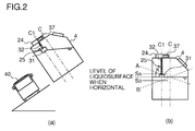
Figs. 2(a) and 2(b) are views useful to describe how the level of the liquid surface to be detected differs depending on the angle of inclination in the embodiment of the present invention. -
Fig. 3 is a flowchart illustrating a control process to be carried out by the SCR system shown inFig. 1 . -
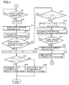
Fig. 4 is another flowchart illustrating the control process of the SCR system ofFig. 1 . -
Fig. 5 is a flowchart illustrating a control process of inclination correction inFigs. 3 and4 . - An embodiment of the present invention will be described with reference to the appended drawings.
-
Figs. 1(a) and 1(b) are schematic configuration diagrams of an SCR system according to an embodiment of the present embodiment. - As illustrated in
Figs. 1(a) and 1(b) , anSCR system 1 primarily includes anSCR device 3 provided on anexhaust pipe 2 of an engine (not illustrated), aurea solution tank 4 for storing a urea solution, a dosing valve (urea solution injection device) 5 that is provided on theexhaust pipe 2 upstream of theSCR device 3 to inject the urea solution, asupply module 6 that supplies the urea solution to thedosing valve 5 from the ureasolution tank 4, and a dosing control unit (DCU) 7 that controls thedosing valve 5, thesupply module 6, and relevant components. - The
dosing valve 5 has a structure in which an injection port is provided in a cylinder filled with a high-pressure urea solution and a valve body for closing the injection port is attached to a plunger. As electricity is passed to a coil, the plunger is lifted to move the valve body away from the injection port, and thus the urea solution is injected. When the passing of electricity to the coil is stopped, the plunger is pulled downward by the spring force thereinside, and the valve body closes the injection port. Thus, the injection of the urea solution is stopped. - An exhaust
gas temperature sensor 8 for measuring the temperature of exhaust gas at an inlet of theSCR device 3 is provided on theexhaust pipe 2 upstream of theSCR device 3, and an output signal line of the exhaustgas temperature sensor 8 is connected to theDCU 7. Anupstream NOx sensor 9 for detecting the NOx concentration at the upstream side of theSCR device 3 is provided on theexhaust pipe 2 upstream of theSCR device 3. Adownstream NOx sensor 10 for detecting the NOx concentration at the downstream side of theSCR device 3 is provided on theexhaust pipe 2 downstream of theSCR device 3.NOx sensor modules NOx sensors NOx sensors NOx sensor modules DCU 7 via a controller area network (CAN). - The DCU 7 is connected to a key switch (ignition switch) 13 and a
battery 14. The DCU 7 is also connected, via the CAN, to an engine control module (ECM) 15 that controls the engine. - The
supply module 6 includes anSM pump 16 for pressurizing and feeding the urea solution, anSM temperature sensor 17 for measuring the temperature of thesupply module 6, a ureasolution pressure sensor 18 for measuring the pressure of the urea solution in the supply module 6 (i.e., the pressure at the discharge side of the SM pump 16), and a revertingvalve 19 for switching between supplying the urea solution from theurea solution tank 4 to thedosing valve 5 and returning the urea solution from the dosing valve to theurea solution tank 4. Output signal lines of theSM temperature sensor 17 and the ureasolution pressure sensor 18 are connected to theDCU 7, and input signal lines of theSM pump 16 and the revertingvalve 19 are connected to theDCU 7. - When the reverting
valve 19 has been switched to supply the urea solution to thedosing valve 5, thesupply module 6 causes theSM pump 16 to suck up the urea solution from the ureasolution tank 4 through a liquid-feed line (suction line) 20, supply the urea solution to thedosing valve 5 via a pressure-feed line (pressure line) 21, and return any excess urea solution to the ureasolution tank 4 via a recovery line (back line) 22. Afilter 23 is disposed in the pressure-feed line 21. - A cooling
water line 28 for circulating cooling water to cool the engine is connected to theurea solution tank 4 and thesupply module 6. The coolingwater line 28 passes through theurea solution tank 4, in which heat is exchanged between the cooling water and the urea solution. The coolingwater line 28 also passes through thesupply module 6, in which heat is exchanged between the cooling water and thesupply module 6. - A
tank heater valve 29 is disposed on thecooling water line 28, which passes through theurea solution tank 4 and thesupply module 6, for switching between introducing and not introducing the cooling water into theurea solution tank 4 and thesupply module 6. An input signal line of thetank heater valve 29 is connected to theDCU 7. Signals may be sent between theDCU 7 and other members via signal lines or via the CAN. - The cooling
water line 28 is connected to thedosing valve 5 as well. The cooling water is supplied to thedosing valve 5 regardless of whether thetank heater valve 29 is open or closed. - The
DCU 7 includes a urea solutioninjection controlling unit 30 that controls an amount of urea solution to be injected through thedosing valve 5 in accordance with an amount of NOx emitted from the engine. The urea solutioninjection controlling unit 30 estimates the amount of NOx contained in the exhaust gas on the basis of engine parameters obtained from theECM 15 and the temperature of the exhaust gas obtained from the exhaustgas temperature sensor 8, and determines the amount of urea solution to be injected through thedosing valve 5 on the basis of the estimated amount of NOx. When the urea solution is injected in the determined amount through thedosing valve 5, the urea solutioninjection controlling unit 30 controls thedosing valve 5 on the basis of the value detected by theupstream NOx sensor 9 to adjust the amount of the urea solution to be injected through thedosing valve 5. - The
urea solution tank 4 has anSCR sensor 24 attached thereto. TheSCR sensor 24 includes a urea solution level sensor (hereinafter simply referred to as "level sensor") 25 for measuring the level of the liquid surface (level) of the urea solution in theurea solution tank 4, atemperature sensor 26 for measuring the temperature of the urea solution in theurea solution tank 4, and aquality sensor 27 for measuring the quality of the urea solution in theurea solution tank 4. Thequality sensor 27 detects, for example, the concentration of the urea solution and/or whether a heterogeneous mixture is mixed in the urea solution on the basis of the propagation speed of an ultrasonic wave or the electric conductivity, and determines the quality of the urea solution in theurea solution tank 4. - The
level sensor 25 is a float level sensor that includes afloat 31 and a detectingunit 32. Thefloat 31 is configured to follow the liquid surface of the urea solution in theurea solution tank 4. The detectingunit 32 is configured to detect the position of thefloat 31 to detect the level of the liquid surface of the urea solution stored in theurea solution tank 4. - The
float 31 is formed into a hollow cylindrical shape and has magnets. The detectingunit 32 includes a pipe to be disposed inside the hollow portion of thefloat 31 and reed switches provided along the longitudinal direction of the pipe at predetermined intervals. The contacts of the reed switches are closed by the magnets provided on thefloat 31. Detecting a reed switch whose contact is closed allows the position (height-wise position) of thefloat 31 to be detected. It should be noted that the configuration of the detectingunit 32 is not limited to the above-described configuration. - The
DCU 7 includes a urea solutionlevel detecting unit 33 that obtains the level of the liquid surface of the urea solution stored in theurea solution tank 4 on the basis of a signal from the detectingunit 32. - The
DCU 7 also includes a cumulative instructed injectionamount calculating unit 34 that obtains a cumulative amount of instructed injection, which is a cumulative value of the instructed injection amounts of the urea solution instructed by the urea solutioninjection controlling unit 30. TheDCU 7 also includes an actual injectionamount calculating unit 35 that obtains an actually injected amount of the urea solution on the basis of the level of the liquid surface of the urea solution. TheDCU 7 also includes a consumption amountabnormality determining unit 36 that determines that the consumption amount is abnormal when the deviation of the actually injected amount from the cumulative instructed injection amount is greater than a predetermined value. - In this embodiment, the consumption amount
abnormality determining unit 36 is configured to determine that the consumption amount is abnormal when a cumulative instructed injection amount P calculated by the cumulative instructed injectionamount calculating unit 34 has reached or exceeded a preset determination amount Pth. - The
SCR system 1 of this embodiment also includes aninclination sensor 37 for detecting an angle of inclination of theurea solution tank 4 relative to the horizontal plane, and aninclination correcting unit 38 that corrects the level of the liquid surface of the urea solution, which is detected by the detectingunit 32 on the basis of the position of thefloat 31, in accordance with the angle of inclination detected by theinclination sensor 37. - The
level sensor 25 is disposed at a position offset from the center position of theurea solution tank 4 as viewed from the above. Theinclination sensor 37 is configured to detect the angle of inclination relative to the horizontal plane in the direction in which thelevel sensor 25 is offset, i.e., in the direction extending from the center position of theurea tank 4 to the center position of thelevel sensor 25 as viewed from the above. In this embodiment, theinclination sensor 37 is disposed on the upper portion of theurea solution tank 4. It should be noted that the position at which theinclination sensor 37 is provided is not limited thereto. For example, theinclination sensor 37 may be provided, for example, on another member that inclines along with theurea solution tank 4. - As illustrated in
Fig. 2(a) , thelevel sensor 25 is disposed at a position C1 that is offset from the center position C of theurea solution tank 4. In this arrangement, the accurate level of the liquid surface cannot be detected when avehicle 40 is inclined since theurea solution tank 4 is inclined relative to the horizontal plane. - As illustrated in
Fig. 2(b) , even if the level of the liquid surface of the urea solution is constant when theurea solution tank 4 is disposed horizontally, a level SA of the liquid surface, which is higher than the level held when theurea solution tank 4 is disposed horizontally, is detected when theurea solution tank 4 is inclined in the counterclockwise direction in the drawing such that the liquid surface lies along the position A. A level SB of the liquid surface, which is lower than the level held when theurea solution tank 4 is disposed horizontally, is detected when theurea solution tank 4 is inclined in the clockwise direction in the drawing such that the liquid surface lies along the position B. Thus, an error occurs in either case. - The error of the level of the liquid surface when the
urea solution tank 4 is inclined relative to the level of the liquid surface when theurea solution tank 4 is disposed horizontally varies with an angle K of inclination. Therefore, in this embodiment, the angle K of inclination relative to the horizontal plane in the direction in which thelevel sensor 25 is offset from the center position C of theurea solution tank 4 is detected by theinclination sensor 37, and the level of the liquid surface when theurea solution tank 4 is inclined is corrected in accordance with the detected angle K of inclination. Thus, the level of the liquid surface when theurea solution tank 4 is disposed horizontally is estimated. - Specifically, the corrected level S' of the liquid surface (i.e., the level of the liquid surface when the
urea solution tank 4 is disposed horizontally) is obtained by Expression (1), where S represents the level of the liquid surface prior to the correction, and K represents the angle of inclination.
level sensor 25. - The actual injection
amount calculating unit 35 is configured to obtain the actually injected amount of urea solution on the basis of the level of the liquid surface of the urea solution corrected by theinclination correcting unit 38. - When the angle K of inclination detected by the
inclination sensor 37 is excessively large, there is a possibility of theinclination sensor 37 malfunctioning or being mounted improperly. Therefore, theSCR system 1 also includes an inclinationabnormality determining unit 39 that determines that the inclination is abnormal when the angle K of inclination detected by theinclination sensor 37 is greater than a preset threshold angle Kth. In this embodiment, the inclinationabnormality determining unit 39 is configured to determine that the inclination is abnormal when the number of times the angle K of inclination is determined to be greater than the threshold angle Kth exceeds a predetermined count. - The control process of the
SCR system 1 will now be described. - As illustrated in
Fig. 3 , 0 is substituted into i in Step S1, and the cumulative amounts and the counter values are reset to their initial states. In Step S2, theSCR system 1 stands by until thekey switch 13 is turned on. Upon turning on of thekey switch 13, the processing proceeds to Step S3, and thelevel sensor 25 reads a level sensor position S1(i), i.e., the level of the liquid surface of the urea solution. In Step S4, processing of inclination correction is carried out. The details of the processing of the inclination correction will be described later. - In Step S5, the cumulative instructed injection
amount calculating unit 34 starts integrating the instructed injection amount. In Step S6, theSCR system 1 stands by until thekey switch 13 is turned off. Upon turning off of thekey switch 13, a level sensor position S2(i) is read in Step S7. The inclination correction is carried out in Step S8. The level of the liquid surface of the urea solution is measured when thekey switch 13 is turned on or turned off because it is believed that the vehicle is stopped when thekey switch 13 is turned on or turned off, and the level of the liquid surface of the urea solution can be measured accurately. - Thereafter, as illustrated in
Fig. 4 , theSCR system 1 stands by until thekey switch 13 is turned on again in Step S9. Upon turning on of thekey switch 13, i is incremented in Step S10. Then, the level sensor position S1(i) is read in Step S11. In Step S12, the inclination correction is carried out. - In Step S13, the consumption amount
abnormality determining unit 36 determines whether the cumulative instructed injection amount P calculated by the cumulative instructed injectionamount calculating unit 34 has reached or exceeded the preset determination amount Pth. - If the determination in Step S13 is NO, i.e., if the cumulative instructed injection amount P has not reached the determination amount Pth, then it is determined in
Step S 14 whether the value obtained by subtracting the level sensor position S1(i) of the current key-on instance from the level sensor position S2(i-1) of the previous key-off instance is greater than a preset replenish threshold Fth. In other words, it is determined whether the urea solution has been replenished within a period from the previous key-off instance to the current key-on instance. If the determination in Step S14 is NO, i.e., if the urea solution has not been replenished, the processing proceeds to Step S16. - If the determination in Step S14 is YES, i.e., if the urea solution has been replenished, then a replenish amount R is calculated in Step S15. The replenish amount R is obtained by subtracting the level sensor position S1(i) of the current key-on instance from the level sensor position S2(i-1) of the previous key-off instance. A cumulative replenish amount RΣ is calculated by integrating the replenish amount R. Then, the processing proceeds to Step S16.
- In Step S16, the instructed injection amount continues to be integrated. In Step S17, the
SCR system 1 stands by until thekey switch 13 is turned off. Upon turning off of thekey switch 13, the level sensor position S2(i) is read in Step S18. The inclination correction is carried out in Step S19, and the processing returns to Step S9. - If the determination in Step S13 is YES, i.e., if the cumulative instructed injection amount P has exceeded the determination amount Pth, then the actual injection
amount calculating unit 35 calculates an actual injection amount Pac in Step S20. The actual injection amount Pac is obtained by subtracting, from the initial level sensor position S1(0), the value obtained by subtracting the cumulative replenish amount RΣ from the current level sensor position S1(i). - In Step S21, the consumption amount
abnormality determining unit 36 determines whether the absolute value of the value obtained by subtracting the cumulative instructed injection amount P from the actual injection amount Pac is greater than a preset threshold Dth. If the determination in Step S21 is YES, this means that the deviation of the actual injection amount Pac from the cumulative instructed injection amount P is large. Thus, it is determined in Step S22 that the consumption amount is abnormal, and processing at the time of abnormality, such as lighting up a fault lamp, is carried out. Then, the processing proceeds to "End." If the determination in Step S21 is NO, this means that the deviation of the actual injection amount Pac from the cumulative instructed injection amount P is small. Thus, it is determined in Step S23 that the consumption amount is normal, and the processing proceeds to "End." - In the inclination correcting process, as illustrated in
Fig. 5 , theinclination correcting unit 38 reads the angle K of inclination from an output of theinclination sensor 37 in Step S31. In Step S32, the inclinationabnormality determining unit 39 determines whether the angle K of inclination is no greater than a preset threshold angle Kth. - If the determination in Step S32 is YES, it is determined that the angle K of inclination is within a normal range. In Step S33, the
inclination correcting unit 38 substitutes, into S1(i) (or S2(i)), the corrected value. The corrected value is obtained by adding a value, which is obtained by multiplying the angle K of inclination by the correction coefficient α, to the detected level sensor position S1(i) (or S2(i)). In the process below, calculation is carried out with the use of the corrected level sensor position S1(i) (or S2(i)). In Step S34, a skip counter C is decremented, and the processing is returned. - If the determination in Step S32 is NO, the skip counter C is incremented in Step S35. Then, it is determined in Step S36 whether the skip counter C is no greater than a preset threshold count Cth. If the determination in Step S36 is YES, the processing returns to Step S9 of
Fig. 4 . - If the determination in Step S36 is NO, i.e., if the number of times the angle K of inclination has exceeded the threshold angle Kth exceeds a threshold Cth, the
inclination correcting unit 38 determines in Step S37 that the inclination is abnormal, and carries out abnormality processing, such as lighting up a fault lamp. Then, in Step S38, the cumulative amounts and the counter values are reset to their initial states. Thereafter, the processing returns to Step S9 ofFig. 4 . - As described above, the
SCR system 1 of this embodiment includes theinclination sensor 37 for detecting the angle of inclination of theurea solution tank 4 relative to the horizontal plane, and theinclination correcting unit 38 that corrects the level of the liquid surface of the urea solution, which is detected by the detectingunit 32 on the basis of the position of thefloat 31, in accordance with the angle of inclination detected by theinclination sensor 37. - The
SCR system 1 includes theinclination sensor 37 and theinclination correcting unit 38. Therefore, even when theurea solution tank 4 is inclined, the level of the liquid surface of the urea solution when theurea solution tank 4 is disposed horizontally can be estimated by making a correction in accordance with the angle of inclination. Thus, the level of the liquid surface of the urea solution can be detected accurately. As a result, even when a vehicle is parked in an inclined manner, for example, the level of the liquid surface of the urea solution can be detected accurately. An erroneous determination or the like in determining the consumption amount abnormality can be suppressed. - The present invention is not limited to the above-described embodiments, and various modifications can be made within the scope that does not depart from the spirit of the present invention.
-
- 1: SCR system
- 2: Exhaust pipe
- 3: SCR device (selective catalytic reduction device)
- 4: Urea solution tank
- 5: Dosing valve
- 30: Urea solution injection controlling unit
- 25: Level sensor
- 31: Float
- 32: Detecting unit
- 37: Inclination sensor
- 38: Inclination correcting unit
Claims (7)
- An SCR system comprising:a selective catalytic reduction device provided on an exhaust pipe of an engine;a urea solution tank configured to store a urea solution;a float urea solution level sensor provided in the urea solution tank, the float urea solution level sensor including:a float configured to follow a liquid surface of the urea solution in the urea solution tank, anddetecting means configured to detect a position of the float to detect a level of the liquid surface of the urea solution stored in the urea solution tank;a dosing valve disposed on the exhaust pipe upstream of the selective catalytic reduction device and configured to inject the urea solution;a urea solution injection controlling unit configured to control an injection amount of the urea solution injected through the dosing valve in accordance with an amount of NOx emitted from the engine;an inclination sensor configured to detect an angle of inclination of the urea solution tank relative to a horizontal plane; andan inclination correcting unit configured to correct the level of the liquid surface of the urea solution, which is detected by the detecting means based on the position of the float, in accordance with the angle of inclination detected by the inclination sensor.
- The SCR system according to claim 1 further comprising an inclination abnormality determining unit configured to determine that inclination is abnormal when the angle of inclination detected by the inclination sensor is greater than a preset threshold angle.
- The SCR system according to claim 1 or 2 further comprising a cumulative instructed injection amount calculating unit configured to obtain a cumulative instructed injection amount, the cumulative instructed injection amount being a cumulative value of an instructed injection amount of the urea solution instructed by the urea solution injection controlling unit;
an actual injection amount calculating unit configured to obtain an actual injection amount of the urea solution based on the level of the liquid surface of the urea solution corrected by the inclination correcting unit; and
a consumption amount abnormality determining unit configured to determine that a consumption amount is abnormal when a deviation of the actual injection amount from the cumulative instructed injection amount is greater than a predetermined value. - An SCR sensor comprising:a float urea solution level sensor provided in a urea solution tank, the urea tank being configured to store a urea solution that is used to purify exhaust gas of an engine, the float urea solution level sensor including:a float configured to follow a liquid surface of the urea solution in the urea solution tank, anddetecting means configured to detect a position of the float to detect a level of the liquid surface of the urea solution stored in the urea solution tank;an inclination sensor configured to detect an angle of inclination of the urea solution tank relative to a horizontal plane; andan inclination correcting unit configured to correct the level of the liquid surface of the urea solution, which is detected by the detecting means based on the position of the float, in accordance with the angle of inclination detected by the inclination sensor.
- The SCR sensor according to claim 4 further comprising an inclination abnormality determining unit configured to determine that inclination is abnormal when the angle of inclination detected by the inclination sensor is greater than a preset threshold angle.
- A float level sensor comprising:a float provided in a tank, the tank being configured to store a liquid, the float being configured to follow a liquid surface of the liquid in the tank;detecting means configured to detect a position of the float to detect a level of the liquid surface of the liquid stored in the tank;an inclination sensor configured to detect an angle of inclination of the tank relative to a horizontal plane; andan inclination correcting unit configured to correct the level of the liquid surface of the liquid, which is detected by the detecting means based on the position of the float, in accordance with the angle of inclination detected by the inclination sensor.
- The level sensor according to claim 6 further comprising an inclination abnormality determining unit configured to determine that inclination is abnormal when the angle of inclination detected by the inclination sensor is greater than a preset threshold angle.
Applications Claiming Priority (2)
| Application Number | Priority Date | Filing Date | Title |
|---|---|---|---|
| JP2013222251A JP6225638B2 (en) | 2013-10-25 | 2013-10-25 | SCR system, SCR sensor, and level sensor |
| PCT/JP2014/077694 WO2015060215A1 (en) | 2013-10-25 | 2014-10-17 | Scr system, scr sensor, and level sensor |
Publications (2)
| Publication Number | Publication Date |
|---|---|
| EP3061934A1 true EP3061934A1 (en) | 2016-08-31 |
| EP3061934A4 EP3061934A4 (en) | 2017-05-31 |
Family
ID=52992812
Family Applications (1)
| Application Number | Title | Priority Date | Filing Date |
|---|---|---|---|
| EP14855819.0A Withdrawn EP3061934A4 (en) | 2013-10-25 | 2014-10-17 | Scr system, scr sensor, and level sensor |
Country Status (5)
| Country | Link |
|---|---|
| US (1) | US10077698B2 (en) |
| EP (1) | EP3061934A4 (en) |
| JP (1) | JP6225638B2 (en) |
| CN (1) | CN105658920B (en) |
| WO (1) | WO2015060215A1 (en) |
Cited By (1)
| Publication number | Priority date | Publication date | Assignee | Title |
|---|---|---|---|---|
| DE102019122289B4 (en) | 2018-10-15 | 2023-01-26 | Toyota Jidosha Kabushiki Kaisha | Control device for internal combustion engine |
Families Citing this family (20)
| Publication number | Priority date | Publication date | Assignee | Title |
|---|---|---|---|---|
| JP6427078B2 (en) * | 2015-08-06 | 2018-11-21 | 本田技研工業株式会社 | Detection device |
| JP6445476B2 (en) * | 2016-01-29 | 2018-12-26 | 日立建機株式会社 | Construction machinery |
| JP6668882B2 (en) * | 2016-03-30 | 2020-03-18 | 三菱自動車工業株式会社 | Additive container |
| EP3480048B1 (en) * | 2017-11-03 | 2020-04-29 | MEAS France | Tank tube bracket for a tank with a diverted discharge opening |
| JP7468985B2 (en) * | 2018-03-22 | 2024-04-16 | 住友建機株式会社 | Excavator |
| FR3093784B1 (en) * | 2019-03-11 | 2021-07-30 | Air Liquide | Liquefied gas storage tank |
| CN112416471A (en) * | 2019-08-23 | 2021-02-26 | 北汽福田汽车股份有限公司 | Tail gas monitoring method and device, computer readable storage medium and electronic equipment |
| CN111360014A (en) * | 2019-09-04 | 2020-07-03 | 添可智能科技有限公司 | Cleaning apparatus, control method thereof, and storage medium |
| CN110906394B (en) * | 2019-11-06 | 2021-08-20 | 宁波方太厨具有限公司 | Oil cup state detection method of range hood |
| CN111173603B (en) * | 2020-01-19 | 2022-06-21 | 无锡威孚力达催化净化器有限责任公司 | Method, device and system for monitoring urea consumption |
| CN111217042A (en) * | 2020-02-24 | 2020-06-02 | 太原理工大学 | A kind of tank complex liquid level measuring device and application method |
| KR102855186B1 (en) * | 2020-07-15 | 2025-09-03 | 현대자동차주식회사 | Liquid storage container |
| CN113370983B (en) * | 2021-06-29 | 2022-12-09 | 东风华神汽车有限公司 | Urea liquid level warning method and computer equipment |
| CN113702301B (en) * | 2021-08-24 | 2025-01-28 | 广州检验检测认证集团有限公司 | A fully automatic pH test system |
| US11945401B2 (en) | 2022-03-31 | 2024-04-02 | Caterpillar Inc. | Detecting sensor malfunction or tampering based on reductant consumption |
| CN115095417B (en) * | 2022-05-19 | 2024-02-20 | 潍柴动力股份有限公司 | A float for a urea tank sensor and a urea tank sensor |
| CN115527351A (en) * | 2022-08-26 | 2022-12-27 | 合肥智圣新创信息技术有限公司 | A smart laboratory operating specification identification system and method |
| CN115683940B (en) * | 2022-11-04 | 2025-09-19 | 潍柴动力股份有限公司 | Vehicle urea concentration detection device and vehicle urea concentration detection method |
| CN118881443B (en) * | 2024-07-31 | 2025-09-09 | 东风商用车有限公司 | Fault locating method, device, equipment and computer readable storage medium |
| CN119687390A (en) * | 2025-02-24 | 2025-03-25 | 常州博瑞电力自动化设备有限公司 | Multifunctional air pressure stabilizing system of water cooling device |
Family Cites Families (24)
| Publication number | Priority date | Publication date | Assignee | Title |
|---|---|---|---|---|
| JPS57117082A (en) * | 1981-01-10 | 1982-07-21 | Hitachi Construction Machinery | Alarm for civil engineering and construction machine |
| JPH05223619A (en) | 1992-02-10 | 1993-08-31 | Toyota Motor Corp | Detector for amount of liquid in tank |
| JP2652299B2 (en) * | 1992-04-06 | 1997-09-10 | 富士山電気工業株式会社 | Work vehicle alarm |
| JP2000313240A (en) * | 1999-05-06 | 2000-11-14 | Komatsu Ltd | Liquid tank residual quantity detector |
| JP2006250117A (en) | 2005-03-14 | 2006-09-21 | Nissan Diesel Motor Co Ltd | Device for judging reducing agent injection condition in exhaust emission control system |
| US8141346B2 (en) * | 2007-01-31 | 2012-03-27 | Ford Global Technologies, Llc | System and method for monitoring reductant quality |
| JP4710868B2 (en) | 2007-04-25 | 2011-06-29 | トヨタ自動車株式会社 | Exhaust gas purification device for internal combustion engine |
| JP4687709B2 (en) * | 2007-04-25 | 2011-05-25 | トヨタ自動車株式会社 | Exhaust gas purification device for internal combustion engine |
| US7954312B2 (en) * | 2007-05-09 | 2011-06-07 | Ford Global Technologies, Llc | Approach for detecting reductant availability and make-up |
| JP2009042131A (en) * | 2007-08-10 | 2009-02-26 | Kanto Auto Works Ltd | Fuel gauge device of fuel tank |
| JP2010151094A (en) * | 2008-12-26 | 2010-07-08 | Bosch Corp | Device and method for detecting leak of reducer |
| JP5255427B2 (en) | 2008-12-26 | 2013-08-07 | 三菱ふそうトラック・バス株式会社 | Urea water tank |
| DE102009045667A1 (en) * | 2009-10-14 | 2011-04-21 | Robert Bosch Gmbh | Device for measuring the level in a liquid container |
| JP5585203B2 (en) * | 2010-05-17 | 2014-09-10 | いすゞ自動車株式会社 | SCR sensor |
| JP5471831B2 (en) * | 2010-05-25 | 2014-04-16 | いすゞ自動車株式会社 | SCR system |
| DE102010035008A1 (en) * | 2010-08-20 | 2012-02-23 | Emitec Gesellschaft Für Emissionstechnologie Mbh | Urea container with ultrasonic sensor |
| US8509983B2 (en) * | 2010-11-12 | 2013-08-13 | GM Global Technology Operations LLC | Diesel-exhaust-fluid refill detection |
| DE102012001580A1 (en) | 2012-01-27 | 2013-08-01 | Daimler Ag | Method for determining filling volume of usage liquid in storage tank of motor vehicle, involves detecting signal of fluid level sensor arranged in storage tank, where ultrasonic sensor is used as fluid level sensor |
| DE102012005281A1 (en) * | 2012-03-16 | 2013-09-19 | Emitec France S.A.S | Feed unit with level sensor for a liquid additive |
| JP5842805B2 (en) * | 2012-12-28 | 2016-01-13 | 株式会社デンソー | Urea water addition controller |
| US9708959B2 (en) * | 2013-07-11 | 2017-07-18 | Ford Global Technologies, Llc | Filtering method for intermittent ultrasonic level sensors |
| JP6219713B2 (en) | 2013-12-25 | 2017-10-25 | トヨタ自動車株式会社 | Liquid level detector |
| DE102014226137A1 (en) * | 2014-12-16 | 2016-06-16 | Robert Bosch Gmbh | Method for determining a filling level of a liquid tank in a motor vehicle |
| JP6228159B2 (en) * | 2015-05-27 | 2017-11-08 | トヨタ自動車株式会社 | Urea water supply device for internal combustion engine |
-
2013
- 2013-10-25 JP JP2013222251A patent/JP6225638B2/en not_active Expired - Fee Related
-
2014
- 2014-10-17 CN CN201480058526.3A patent/CN105658920B/en not_active Expired - Fee Related
- 2014-10-17 US US15/029,463 patent/US10077698B2/en not_active Expired - Fee Related
- 2014-10-17 WO PCT/JP2014/077694 patent/WO2015060215A1/en not_active Ceased
- 2014-10-17 EP EP14855819.0A patent/EP3061934A4/en not_active Withdrawn
Cited By (1)
| Publication number | Priority date | Publication date | Assignee | Title |
|---|---|---|---|---|
| DE102019122289B4 (en) | 2018-10-15 | 2023-01-26 | Toyota Jidosha Kabushiki Kaisha | Control device for internal combustion engine |
Also Published As
| Publication number | Publication date |
|---|---|
| US10077698B2 (en) | 2018-09-18 |
| EP3061934A4 (en) | 2017-05-31 |
| JP6225638B2 (en) | 2017-11-08 |
| WO2015060215A1 (en) | 2015-04-30 |
| CN105658920A (en) | 2016-06-08 |
| CN105658920B (en) | 2018-07-27 |
| JP2015083796A (en) | 2015-04-30 |
| US20160273429A1 (en) | 2016-09-22 |
Similar Documents
| Publication | Publication Date | Title |
|---|---|---|
| US10077698B2 (en) | Selective catalytic reduction system, selective catalytic reduction sensor, and level sensor | |
| JP5471831B2 (en) | SCR system | |
| JP6136297B2 (en) | Urea water consumption diagnostic device for urea SCR | |
| US8955308B2 (en) | Method for operating a reducing agent tank and motor vehicle in which the method is carried out | |
| JP6127510B2 (en) | Urea water consumption diagnostic device for urea SCR | |
| EP2573344B1 (en) | Validity diagnosis system for urea water temperature sensor | |
| JP2004510151A (en) | Method and apparatus for measuring the level of liquid in a tank | |
| US9991531B2 (en) | Fuel cell system | |
| JP5195283B2 (en) | Engine exhaust purification system | |
| EP2573343B1 (en) | Competency diagnosis system for urea water temperature sensor | |
| JP6127509B2 (en) | Urea water consumption diagnostic device for urea SCR | |
| KR101427956B1 (en) | Urea solution quality determination system | |
| JP5240065B2 (en) | Failure detection device for exhaust gas purification device | |
| JP5842805B2 (en) | Urea water addition controller | |
| KR101838357B1 (en) | Fuel cell system | |
| EP2784279A1 (en) | Exhaust purification device for internal combustion engine | |
| US20170241315A1 (en) | Abnormality diagnosis device for exhaust gas purification apparatus in internal combustion engine | |
| JP4341606B2 (en) | Fuel injection device for internal combustion engine | |
| KR20140005331A (en) | Method and device for determining the dosed reducing agent volume in an scr system | |
| JP2016169654A (en) | NOx sensor inspection program, NOx sensor inspection device, internal combustion engine, and NOx sensor inspection method | |
| KR20110110029A (en) | Reducing agent concentration measuring device of SCR system for diesel vehicle | |
| KR101679983B1 (en) | Urea supply apparatus and method |
Legal Events
| Date | Code | Title | Description |
|---|---|---|---|
| PUAI | Public reference made under article 153(3) epc to a published international application that has entered the european phase |
Free format text: ORIGINAL CODE: 0009012 |
|
| 17P | Request for examination filed |
Effective date: 20160503 |
|
| AK | Designated contracting states |
Kind code of ref document: A1 Designated state(s): AL AT BE BG CH CY CZ DE DK EE ES FI FR GB GR HR HU IE IS IT LI LT LU LV MC MK MT NL NO PL PT RO RS SE SI SK SM TR |
|
| AX | Request for extension of the european patent |
Extension state: BA ME |
|
| DAX | Request for extension of the european patent (deleted) | ||
| A4 | Supplementary search report drawn up and despatched |
Effective date: 20170504 |
|
| RIC1 | Information provided on ipc code assigned before grant |
Ipc: F02D 45/00 20060101ALI20170426BHEP Ipc: F01N 11/00 20060101ALI20170426BHEP Ipc: F01N 9/00 20060101ALI20170426BHEP Ipc: F01N 3/08 20060101AFI20170426BHEP |
|
| STAA | Information on the status of an ep patent application or granted ep patent |
Free format text: STATUS: THE APPLICATION HAS BEEN WITHDRAWN |
|
| 18W | Application withdrawn |
Effective date: 20171114 |