EP3061932A1 - Exhaust device of motorcycle - Google Patents
Exhaust device of motorcycle Download PDFInfo
- Publication number
- EP3061932A1 EP3061932A1 EP16156758.1A EP16156758A EP3061932A1 EP 3061932 A1 EP3061932 A1 EP 3061932A1 EP 16156758 A EP16156758 A EP 16156758A EP 3061932 A1 EP3061932 A1 EP 3061932A1
- Authority
- EP
- European Patent Office
- Prior art keywords
- exhaust
- oxygen sensor
- catalyst
- pair
- merging
- Prior art date
- Legal status (The legal status is an assumption and is not a legal conclusion. Google has not performed a legal analysis and makes no representation as to the accuracy of the status listed.)
- Granted
Links
Images



Classifications
-
- F—MECHANICAL ENGINEERING; LIGHTING; HEATING; WEAPONS; BLASTING
- F01—MACHINES OR ENGINES IN GENERAL; ENGINE PLANTS IN GENERAL; STEAM ENGINES
- F01N—GAS-FLOW SILENCERS OR EXHAUST APPARATUS FOR MACHINES OR ENGINES IN GENERAL; GAS-FLOW SILENCERS OR EXHAUST APPARATUS FOR INTERNAL-COMBUSTION ENGINES
- F01N13/00—Exhaust or silencing apparatus characterised by constructional features
- F01N13/08—Other arrangements or adaptations of exhaust conduits
- F01N13/10—Other arrangements or adaptations of exhaust conduits of exhaust manifolds
- F01N13/107—More than one exhaust manifold or exhaust collector
-
- F—MECHANICAL ENGINEERING; LIGHTING; HEATING; WEAPONS; BLASTING
- F01—MACHINES OR ENGINES IN GENERAL; ENGINE PLANTS IN GENERAL; STEAM ENGINES
- F01N—GAS-FLOW SILENCERS OR EXHAUST APPARATUS FOR MACHINES OR ENGINES IN GENERAL; GAS-FLOW SILENCERS OR EXHAUST APPARATUS FOR INTERNAL-COMBUSTION ENGINES
- F01N1/00—Silencing apparatus characterised by method of silencing
-
- F—MECHANICAL ENGINEERING; LIGHTING; HEATING; WEAPONS; BLASTING
- F01—MACHINES OR ENGINES IN GENERAL; ENGINE PLANTS IN GENERAL; STEAM ENGINES
- F01N—GAS-FLOW SILENCERS OR EXHAUST APPARATUS FOR MACHINES OR ENGINES IN GENERAL; GAS-FLOW SILENCERS OR EXHAUST APPARATUS FOR INTERNAL-COMBUSTION ENGINES
- F01N13/00—Exhaust or silencing apparatus characterised by constructional features
- F01N13/008—Mounting or arrangement of exhaust sensors in or on exhaust apparatus
-
- F—MECHANICAL ENGINEERING; LIGHTING; HEATING; WEAPONS; BLASTING
- F01—MACHINES OR ENGINES IN GENERAL; ENGINE PLANTS IN GENERAL; STEAM ENGINES
- F01N—GAS-FLOW SILENCERS OR EXHAUST APPARATUS FOR MACHINES OR ENGINES IN GENERAL; GAS-FLOW SILENCERS OR EXHAUST APPARATUS FOR INTERNAL-COMBUSTION ENGINES
- F01N13/00—Exhaust or silencing apparatus characterised by constructional features
- F01N13/011—Exhaust or silencing apparatus characterised by constructional features having two or more purifying devices arranged in parallel
-
- F—MECHANICAL ENGINEERING; LIGHTING; HEATING; WEAPONS; BLASTING
- F01—MACHINES OR ENGINES IN GENERAL; ENGINE PLANTS IN GENERAL; STEAM ENGINES
- F01N—GAS-FLOW SILENCERS OR EXHAUST APPARATUS FOR MACHINES OR ENGINES IN GENERAL; GAS-FLOW SILENCERS OR EXHAUST APPARATUS FOR INTERNAL-COMBUSTION ENGINES
- F01N13/00—Exhaust or silencing apparatus characterised by constructional features
- F01N13/08—Other arrangements or adaptations of exhaust conduits
- F01N13/10—Other arrangements or adaptations of exhaust conduits of exhaust manifolds
-
- F—MECHANICAL ENGINEERING; LIGHTING; HEATING; WEAPONS; BLASTING
- F01—MACHINES OR ENGINES IN GENERAL; ENGINE PLANTS IN GENERAL; STEAM ENGINES
- F01N—GAS-FLOW SILENCERS OR EXHAUST APPARATUS FOR MACHINES OR ENGINES IN GENERAL; GAS-FLOW SILENCERS OR EXHAUST APPARATUS FOR INTERNAL-COMBUSTION ENGINES
- F01N2260/00—Exhaust treating devices having provisions not otherwise provided for
-
- F—MECHANICAL ENGINEERING; LIGHTING; HEATING; WEAPONS; BLASTING
- F01—MACHINES OR ENGINES IN GENERAL; ENGINE PLANTS IN GENERAL; STEAM ENGINES
- F01N—GAS-FLOW SILENCERS OR EXHAUST APPARATUS FOR MACHINES OR ENGINES IN GENERAL; GAS-FLOW SILENCERS OR EXHAUST APPARATUS FOR INTERNAL-COMBUSTION ENGINES
- F01N2340/00—Dimensional characteristics of the exhaust system, e.g. length, diameter or volume of the exhaust apparatus; Spatial arrangements of exhaust apparatuses
-
- F—MECHANICAL ENGINEERING; LIGHTING; HEATING; WEAPONS; BLASTING
- F01—MACHINES OR ENGINES IN GENERAL; ENGINE PLANTS IN GENERAL; STEAM ENGINES
- F01N—GAS-FLOW SILENCERS OR EXHAUST APPARATUS FOR MACHINES OR ENGINES IN GENERAL; GAS-FLOW SILENCERS OR EXHAUST APPARATUS FOR INTERNAL-COMBUSTION ENGINES
- F01N2340/00—Dimensional characteristics of the exhaust system, e.g. length, diameter or volume of the exhaust apparatus; Spatial arrangements of exhaust apparatuses
- F01N2340/04—Arrangement of the exhaust system relative to a vehicle or parts thereof
-
- F—MECHANICAL ENGINEERING; LIGHTING; HEATING; WEAPONS; BLASTING
- F01—MACHINES OR ENGINES IN GENERAL; ENGINE PLANTS IN GENERAL; STEAM ENGINES
- F01N—GAS-FLOW SILENCERS OR EXHAUST APPARATUS FOR MACHINES OR ENGINES IN GENERAL; GAS-FLOW SILENCERS OR EXHAUST APPARATUS FOR INTERNAL-COMBUSTION ENGINES
- F01N2470/00—Structure or shape of exhaust gas passages, pipes or tubes
- F01N2470/20—Dimensional characteristics of tubes, e.g. length, diameter
-
- F—MECHANICAL ENGINEERING; LIGHTING; HEATING; WEAPONS; BLASTING
- F01—MACHINES OR ENGINES IN GENERAL; ENGINE PLANTS IN GENERAL; STEAM ENGINES
- F01N—GAS-FLOW SILENCERS OR EXHAUST APPARATUS FOR MACHINES OR ENGINES IN GENERAL; GAS-FLOW SILENCERS OR EXHAUST APPARATUS FOR INTERNAL-COMBUSTION ENGINES
- F01N2560/00—Exhaust systems with means for detecting or measuring exhaust gas components or characteristics
- F01N2560/02—Exhaust systems with means for detecting or measuring exhaust gas components or characteristics the means being an exhaust gas sensor
- F01N2560/025—Exhaust systems with means for detecting or measuring exhaust gas components or characteristics the means being an exhaust gas sensor for measuring or detecting O2, e.g. lambda sensors
-
- F—MECHANICAL ENGINEERING; LIGHTING; HEATING; WEAPONS; BLASTING
- F01—MACHINES OR ENGINES IN GENERAL; ENGINE PLANTS IN GENERAL; STEAM ENGINES
- F01N—GAS-FLOW SILENCERS OR EXHAUST APPARATUS FOR MACHINES OR ENGINES IN GENERAL; GAS-FLOW SILENCERS OR EXHAUST APPARATUS FOR INTERNAL-COMBUSTION ENGINES
- F01N2560/00—Exhaust systems with means for detecting or measuring exhaust gas components or characteristics
- F01N2560/06—Exhaust systems with means for detecting or measuring exhaust gas components or characteristics the means being a temperature sensor
-
- F—MECHANICAL ENGINEERING; LIGHTING; HEATING; WEAPONS; BLASTING
- F01—MACHINES OR ENGINES IN GENERAL; ENGINE PLANTS IN GENERAL; STEAM ENGINES
- F01N—GAS-FLOW SILENCERS OR EXHAUST APPARATUS FOR MACHINES OR ENGINES IN GENERAL; GAS-FLOW SILENCERS OR EXHAUST APPARATUS FOR INTERNAL-COMBUSTION ENGINES
- F01N2590/00—Exhaust or silencing apparatus adapted to particular use, e.g. for military applications, airplanes, submarines
- F01N2590/04—Exhaust or silencing apparatus adapted to particular use, e.g. for military applications, airplanes, submarines for motorcycles
Definitions
- the present invention relates to an exhaust device of a motorcycle equipped with an oxygen sensor.
- An exhaust device for an internal combustion engine which is equipped with an oxygen sensor is known (see, for example, Fig. 1 of JP-A-2003-314383 ).
- an exhaust passage (7) extends from an internal combustion engine (1) (numerals in parentheses correspond to the reference numerals used in JP-A-2003-314383 ), a catalyst (8) which purifies an exhaust gas is provided at a middle portion of the exhaust passage (7), an oxygen sensor (27a) is arranged upstream of the catalyst (8), and another oxygen sensor (27b) is arranged downstream of the catalyst (8).
- exhaust gases discharged from the respective cylinders flow through separate exhaust pipes and, thereafter, are merged together by a merging pipe connected to downstream ends of these exhaust pipes.
- a merging pipe connected to downstream ends of these exhaust pipes.
- an engine of the motorcycle In mounting an exhaust device on a motorcycle, it may be the case that an engine of the motorcycle is exposed to the outside of the motorcycle.
- the exhaust device In a vehicle where an engine is exposed to the outside, the exhaust device may be exposed to a natural environment such as rain and a traveling wind. If the catalyst is exposed to rain or a traveling wind, the exhaust device is likely to be cooled and hence, it is possible that the purification performance of the catalyst will be lowered. Accordingly, when a temperature around the catalyst is not fixed, it is necessary to use a catalyst having a volume slightly larger than usual, to take into account the lowering of purification performance of the catalyst caused by an external environment. In this case, the catalyst becomes large.
- an exhaust device for a motorcycle comprising: a pair of left and right exhaust pipes for discharging an exhaust gas from a multi-cylinder engine; and a muffler connected to a downstream side of the exhaust pipe, the muffler being provided for reducing an exhaust noise and for discharging an exhaust gas to the outside, wherein the pair of left and right exhaust pipes includes a merging portion for merging exhaust pipes from respective cylinders respectively, and a catalyst for purifying an exhaust gas is provided in the merging portion respectively, and the pair of left and right exhaust pipes includes, downstream of the catalyst, a branching portion which has one side thereof extending to the muffler and the other side thereof extending to a connecting pipe which connects the pair of left and right exhaust pipes to each other, and an oxygen sensor is provided to said one side on a downstream side of the pair of left and right branching portions, whereby an exhaust gas is stirred in a rear portion of the merging portion and the branching portion.
- exhaust gas passes through the catalyst disposed in the merging portion of the exhaust pipes, and reaches the pair of left and right branching portions.
- the exhaust gas is expanded and stirred in the rear portion of the merging portion and the left and right branching portions.
- the exhaust gas sufficiently stirred in the left and right branching portions comes into contact with the oxygen sensor provided to one downstream side of the branching portion. Accordingly, a state of the catalyst can be more accurately determined.
- a temperature sensor is provided on the branching portion upstream of the oxygen sensor.
- the temperature sensor is arranged at a position closer to the catalyst than the oxygen sensor is, and hence, a reaction heat generated by a chemical reaction of the catalyst can be detected more accurately.
- the degree of activation of the catalyst and a state of the catalyst can be more accurately determined not only by the oxygen sensor but also by the temperature sensor. Since an activation state of the catalyst can be grasped more accurately, the size of the catalyst can be reduced.
- an upper end of the oxygen sensor is directed laterally inwardly, and overlaps with left and right protectors which cover the pair of left and right exhaust pipes as viewed in a side view of the vehicle.
- the oxygen sensor is not exposed laterally to the outside, and so it is possible to provide a structure which is minimally cooled by an external environment such as rain or a traveling wind. As a result, a state of the catalyst can be determined more accurately.
- the connecting pipe is arranged below the oxygen sensor and is arranged so as to overlap with the oxygen sensor in a longitudinal direction of the vehicle.
- the oxygen sensor is minimally cooled by an external environment such as a traveling wind, mud or water, and the oxygen sensor can determine a state of the catalyst more accurately.
- a motorcycle 10 is a saddle-ride-type vehicle where a main frame 13 which extends from a head pipe 12 toward a rear of the vehicle, and a pivot frame 18 which extends downward from the main frame 13 are mounted on a vehicle body frame 11.
- An engine 14 is suspended from the vehicle body frame 11.
- a front wheel steering portion 12 including a front wheel 15 is mounted on the head pipe 12 in a steerable manner.
- a rear wheel suspension portion 22 is supported on the pivot frame 18 in a swingable manner.
- a seat 17 is mounted on the vehicle body frame 11 between the front wheel 15 and the rear wheel 16, and an occupant rides on the vehicle in a state where the rider straddles the seat 17.
- the front wheel steering portion 21 which is mounted on the vehicle body frame 11 in a steerable manner includes, as main constitutional elements thereof: a front fork 24 which is mounted on the head pipe 12 in a rotatable manner; the front wheel 15 which is supported on a lower end of the front fork 24; and a steering handlebar 25 which is mounted on an upper end of the front fork 24.
- the rear wheel suspension portion 22 includes: a swing arm 19 which extends toward the rear of the vehicle from the pivot frame 18, and the rear wheel 16 which is supported on a rear end portion of the swing arm 19.
- a vehicle body cover 30 which covers a vehicle body includes: a front cowl 31; left and right front side cowls 32L, 32R (only the front side cowl 32L on the viewer's side in the drawing is shown) which extend toward the rear of the vehicle from the front cowl 31 up to an upper side of the engine 14; an under cowl 33 which covers the engine 14 from below and an exhaust device 40; and left and right protectors 34L, 34R (only the protector 34L on the viewer's side in the drawing is shown) which are disposed continuously with a rear side of the under cowl 33 and cover the exhaust device 40.
- Left and right trunks 36L, 36R for storing articles are disposed on lateral sides of the rear wheel 16 at a rear portion of the vehicle, and a rear trunk 37 is arranged above the left and right trunks 36L, 36R.
- a front fender 38 for preventing sticking of mud splashed by the front wheel 15 is mounted on the front fork 24.
- the engine 14 mounted on the motorcycle 10 is a horizontally opposed six-cylinder engine.
- the exhaust device 40 is provided to the multi-cylinder engine.
- cylinder portions 42L, 42R of the engine 14 are disposed on left and right sides in the lateral direction of the vehicle.
- Exhaust pipes 41 La, 41 Lb, 41 Lc, 41 Ra, 41 Rb, 41 Rc for discharging an exhaust gas extend from lower surfaces 42Lb, 42Rb of the cylinder portions 42L, 42R respectively.
- Left and right merging portions 43L, 43R are connected to downstream sides of the pair of left and right exhaust pipes 41 L (41 La, 41 Lb, 41 Lc), 41 R (41 Ra, 41 Rb, 41 Rc) respectively, and mufflers 44L, 44R for reducing exhaust noises and for discharging an exhaust gas to the outside are connected to downstream parts of the left and right merging portions 43L, 43R respectively.
- Foot rests 46L, 46R on which an occupant places his or her feet are mounted on the pivot frame 18, and a main stand 47 is mounted on the pivot frame 18.
- the pair of left and right exhaust pipes 41 L, 41 R extends toward the rear of the vehicle.
- the pair of left and right exhaust pipes 41 L, 41 R respectively includes the merging portion 43L, 43R where the respective exhaust pipes are merged together.
- a catalyst 48L, 48R for purifying an exhaust gas is disposed in the merging portions 43L, 43R respectively.
- An upstream-side oxygen sensor 51 L, 51 R is provided on the pair of left and right exhaust pipes 41 L, 41 R, on an upstream side of the catalysts 48L, 48R respectively.
- the pair of left and right exhaust pipes 41 L, 41 R respectively includes a branching portion 55L, 55R, which has one side thereof extending to the mufflers 44L, 44R (see Fig. 2 ) and the other end thereof extending to a connecting pipe 54 which connects the pair of left and right exhaust pipes 41 L, 41 R to each other.
- a downstream-side oxygen sensor 52 is provided on a downstream side of the right branching portion 55R out of the pair of left and right branching portions 55L, 55R.
- rear portions of the merging portions 43L, 43R and the branching portions 55L, 55R are configured to have a larger cross-sectional area (in a cross-section taken perpendicular to the longitudinal direction of the exhaust pipe) than other portions of the exhaust pipe.
- a temperature sensor 53 is further provided to the branching portion 55R, upstream of the downstream-side oxygen sensor 52.
- the downstream-side oxygen sensor 52 is simply referred to as an oxygen sensor 52.
- the merging potion 43L is provided at a downstream part of the exhaust pipe 41 L.
- the merging portion 43L includes: a first merging portion 61 L to which three exhaust pipes 41 La, 41 Lb, 41 Lc are merged together and whose diameter is decreased so as to decrease a cross-sectional area of the exhaust pipe 41 L; a second merging portion 62L which is connected to a downstream end of the first merging portion 61 L, has a constant cross-sectional area and extends toward the rear of the vehicle; a third merging portion 63L which is connected to a downstream end of the second merging portion 62L, has a diameter which enlarges in the direction of exhaust gas flow so as to increase the cross-sectional area of the exhaust pipe 41 L and eventually has a cross-sectional area larger than respective cross-sectional areas of the first merging portion 61 L and the second merging portion 62L, and accommodates the catalyst 48L (see Fig. 2 ) therein; and the branching portion
- a first side extending portion 65L which extends toward the rear of the vehicle and a second side extending portion 66L which extends laterally inward are provided at a downstream side of the branching portion 55L respectively.
- the connecting pipe 54 is connected to the second side extending portion 66L.
- the second side extending portion 66L and the connecting pipe 54 are formed integrally with each other in this embodiment.
- the second side extending portion and the connecting pipe may be formed separately from each other without any problems.
- the connecting pipe 54 is arranged such that the connecting pipe 54 is disposed below the oxygen sensor 52 and overlaps with the oxygen sensor 52 in the longitudinal (front-rear) direction of the vehicle.
- An exhaust pipe stay 69 provided for mounting the exhaust pipe 41 L on the vehicle body frame extends upward from the third merging portion 63L.
- the right branching portion is arranged so as to be in lateral symmetry with the left branching potion with respect to a longitudinal centreline of the vehicle (that is, a centreline extending in the front-rear direction), and so detailed explanation of the structure of the right branching portion is omitted.
- the oxygen sensor 52 is provided on the right first side extending portion 65R.
- an upstream-side boss 67R is mounted on the second merging portion 62R which forms the merging portion 43R, and the upstream-side oxygen sensor 51 R is mounted on the upstream-side boss 67R.
- the upstream-side oxygen sensor 51 R is arranged in an inclined manner with respect to the horizontal direction such that an axis 51 RX of the upstream-side oxygen sensor is directed laterally inwards.
- the right second merging portion 62R including the upstream-side oxygen sensor is arranged so as to be laterally symmetric with the left second merging portion with respect to a longitudinal centreline of the vehicle, and so detailed explanation of the structure of the right second merging portion is omitted.
- the third merging portion 63R which forms the merging portion is formed from an upper half body 75 and a lower half body 76 respectively, which each have a generally semi-elliptical shape and vertically abut each other.
- the catalyst 48R for purifying an exhaust gas is accommodated in the third merging portion 63.
- the left third merging portion is arranged so as to be laterally symmetric with the right third merging portion with respect to a longitudinal centreline of the vehicle, and so detailed explanation of the structure of the left third merging portion is omitted.
- the branching portion 55R which extends contiguously from the third merging portion 63R includes: a ceiling wall 71 which is provided at a downstream side of the catalyst 48R; a bottom wall 72 which is arranged to face the ceiling wall 71 in an opposed manner; and a rear wall 73 which extends between the ceiling wall 71 and the bottom wall 72 and faces the rear of the vehicle.
- a temperature sensor boss 58 is mounted on the rear wall 73, and the temperature sensor 53 is mounted on the temperature sensor boss 58.
- a longitudinal axis 53X of the temperature sensor 53 extends so as to be directed toward the rear of the vehicle.
- the left branching portion and the right branching portion are arranged so as to be laterally symmetric with respect to a longitudinal centreline of the vehicle, and so a detailed explanation of the structure of the left branching portion is omitted.
- an oxygen sensor boss 68 is mounted on the first side extending portion 65R of the branching portion 55R, and the oxygen sensor 52 is mounted on the oxygen sensor boss 68.
- a longitudinal axis 52X of the oxygen sensor 52 extends so as to be directed laterally inwardly with respect to the vehicle. That is, an upper end 52a of the oxygen sensor 52 is directed laterally inwardly.
- the right protector 34R which covers the exhaust pipe 41 is arranged laterally outside the first side extending portion 65R of the exhaust pipe 41. That is, the right protector 34R covers the right exhaust pipe 41 R when viewed in a side view of the vehicle.
- the left protector 34L (see Fig. 1 ) which covers the exhaust pipe 41 is arranged on a left side of the vehicle.
- the left protector 34L and the right protector have a symmetrical structure with respect to a longitudinal centreline of the vehicle, and so a detailed explanation of the structure of the left protector 34L is omitted.
- the oxygen sensor 52 is provided to one side (the rear side in the longitudinal direction of the vehicle) of the right exhaust pipe 41.
- An exhaust gas passes through the catalysts 48L, 48R disposed in the merging portions 43L, 43R of the exhaust pipe 41, and reaches the pair of left and right branching portions 55L, 55R.
- the exhaust gas is expanded and stirred in the rear portions of the merging portions 43L, 43R and the left and right branching portions 55L, 55R.
- the exhaust gas stirred in the left and right branching portions 55L, 55R is brought into contact with the oxygen sensor 52 provided to one side (the rear side in the longitudinal direction of the vehicle) of the right exhaust pipe 41 on the downstream side of the branching portions 55L, 55R. Accordingly, a state of the catalyst 48R can be determined more accurately.
- the temperature sensor 53 is provided to the right branching portion 55R upstream of the oxygen sensor 52.
- the temperature sensor 53 is arranged at a position closer to the catalyst 48R than the oxygen sensor 52 is, and hence, a reaction heat generated by a chemical reaction of the catalyst 48R can be detected more accurately.
- the degree of activation of the catalyst 48R and a state of the catalyst 48R can be further accurately determined not only by the oxygen sensor 52 but also by the temperature sensor 53. Since an activation state of the catalyst 48R can be determined more accurately, a reduction in the size of the catalyst 48R can be achieved.
- the oxygen sensor and the temperature sensor are provided at the downstream side of the right exhaust pipe, and neither the oxygen sensor nor the temperature sensor are provided on the downstream side of the left exhaust pipe.
- the oxygen sensor and the temperature sensor may be provided on the downstream side of the left exhaust pipe without any problems.
- both the oxygen sensor and the temperature sensor may be provided on the downstream sides of both the left and right exhaust pipes. That is, the oxygen sensor and the temperature sensor may be arranged as desired.
- the upper end 52a of the oxygen sensor 52 is directed laterally inwardly, and overlaps with the left and right protectors 35L, 35R which cover the pair of left and right exhaust pipes 41 L, 41 R.
- the oxygen sensor 52 is arranged so that it is not exposed to the outside in the lateral direction of the vehicle, and hence, it is possible to provide a structure which is minimally cooled by an external environment such as rain or a traveling wind. As a result, a state of the catalysts 48L, 48R can be determined more accurately.
- the connecting pipe 54 is arranged such that the connecting pipe 54 is below the oxygen sensor 52 and overlaps with the oxygen sensor 52 in a longitudinal direction of the vehicle.
- a traveling wind which flows below the vehicle, water splashed up by the front wheel 15 (see Fig. 1 ) or the like will thus tend to hit the connecting pipe 54 arranged below the oxygen sensor 52, and hence, a traveling wind, water or the like minimally hits the oxygen sensor 52.
- the oxygen sensor 52 is minimally cooled by an external environment such as a traveling wind or water, and so the oxygen sensor 52 can determine a state of the catalysts 48L, 48R more accurately.
- the invention is applied to a motorcycle in this embodiment, the invention is also applicable to a three-wheeled vehicle and may be applied to vehicles in general without any problems.
- the invention is preferably applied to a motorcycle where an oxygen sensor is provided downstream of a catalyst in an exhaust device of an engine.
Landscapes
- Engineering & Computer Science (AREA)
- Chemical & Material Sciences (AREA)
- Combustion & Propulsion (AREA)
- Mechanical Engineering (AREA)
- General Engineering & Computer Science (AREA)
- Analytical Chemistry (AREA)
- Exhaust Silencers (AREA)
- Exhaust Gas After Treatment (AREA)
Abstract
Description
- The present invention relates to an exhaust device of a motorcycle equipped with an oxygen sensor.
- An exhaust device for an internal combustion engine which is equipped with an oxygen sensor is known (see, for example,
Fig. 1 ofJP-A-2003-314383 - As shown in
Fig. 1 ofJP-A-2003-314383 JP-A-2003-314383 - In an internal combustion engine having a plurality of cylinders, exhaust gases discharged from the respective cylinders flow through separate exhaust pipes and, thereafter, are merged together by a merging pipe connected to downstream ends of these exhaust pipes. In this case, when the exhaust pipes extend linearly from the respective cylinders, it is possible that exhaust gas discharged from the respective cylinders is not sufficiently stirred (or mixed) inside the merging pipe. In this case, data obtained by an oxygen sensor which is arranged inside the merging pipe and detects oxygen in an exhaust gas is likely to only relate to a local area in the merging pipe.
- Further, when a catalyst and an exhaust gas chemically react with each other, a difference in chemical reaction speed can arise depending on differing conditions in different portions of the catalyst. Accordingly, when an oxygen sensor is arranged downstream of the catalyst, unless an exhaust gas which reacts with a catalyst is sufficiently stirred, data obtained by the oxygen sensor is again likely to only relate to a local area in the merging pipe. Accordingly, in the case where an oxygen sensor is provided upstream and downstream of a catalyst, it is desirable to homogenize an exhaust gas by sufficiently stirring the exhaust gas.
- In mounting an exhaust device on a motorcycle, it may be the case that an engine of the motorcycle is exposed to the outside of the motorcycle. In a vehicle where an engine is exposed to the outside, the exhaust device may be exposed to a natural environment such as rain and a traveling wind. If the catalyst is exposed to rain or a traveling wind, the exhaust device is likely to be cooled and hence, it is possible that the purification performance of the catalyst will be lowered. Accordingly, when a temperature around the catalyst is not fixed, it is necessary to use a catalyst having a volume slightly larger than usual, to take into account the lowering of purification performance of the catalyst caused by an external environment. In this case, the catalyst becomes large.
- There has been a desire for an exhaust device of a motorcycle which can detect oxygen in an exhaust gas in a state where the exhaust gas is sufficiently stirred, and also can avoid an increase in the size of a catalyst.
- It is an object of at least the preferred embodiment of the invention to provide an exhaust device of a motorcycle which can detect oxygen in an exhaust gas in a state where the exhaust gas is sufficiently stirred, and also avoid an increase in the size of a catalyst.
- According to a first aspect of the invention, there is provided an exhaust device for a motorcycle comprising: a pair of left and right exhaust pipes for discharging an exhaust gas from a multi-cylinder engine; and a muffler connected to a downstream side of the exhaust pipe, the muffler being provided for reducing an exhaust noise and for discharging an exhaust gas to the outside, wherein the pair of left and right exhaust pipes includes a merging portion for merging exhaust pipes from respective cylinders respectively, and a catalyst for purifying an exhaust gas is provided in the merging portion respectively, and the pair of left and right exhaust pipes includes, downstream of the catalyst, a branching portion which has one side thereof extending to the muffler and the other side thereof extending to a connecting pipe which connects the pair of left and right exhaust pipes to each other, and an oxygen sensor is provided to said one side on a downstream side of the pair of left and right branching portions, whereby an exhaust gas is stirred in a rear portion of the merging portion and the branching portion.
- With this arrangement, exhaust gas passes through the catalyst disposed in the merging portion of the exhaust pipes, and reaches the pair of left and right branching portions. At this stage of operation, the exhaust gas is expanded and stirred in the rear portion of the merging portion and the left and right branching portions. The exhaust gas sufficiently stirred in the left and right branching portions comes into contact with the oxygen sensor provided to one downstream side of the branching portion. Accordingly, a state of the catalyst can be more accurately determined.
- Preferably, a temperature sensor is provided on the branching portion upstream of the oxygen sensor.
- Thus, the temperature sensor is arranged at a position closer to the catalyst than the oxygen sensor is, and hence, a reaction heat generated by a chemical reaction of the catalyst can be detected more accurately. The degree of activation of the catalyst and a state of the catalyst can be more accurately determined not only by the oxygen sensor but also by the temperature sensor. Since an activation state of the catalyst can be grasped more accurately, the size of the catalyst can be reduced.
- Preferably, an upper end of the oxygen sensor is directed laterally inwardly, and overlaps with left and right protectors which cover the pair of left and right exhaust pipes as viewed in a side view of the vehicle.
- With this arrangement, the oxygen sensor is not exposed laterally to the outside, and so it is possible to provide a structure which is minimally cooled by an external environment such as rain or a traveling wind. As a result, a state of the catalyst can be determined more accurately.
- Preferably, the connecting pipe is arranged below the oxygen sensor and is arranged so as to overlap with the oxygen sensor in a longitudinal direction of the vehicle.
- With this arrangement, a traveling wind which flows below the vehicle, and mud or water splashed up by a front wheel or the like, hits the connecting pipe arranged below the oxygen sensor rather than hitting the oxygen sensor. Accordingly, the oxygen sensor is minimally cooled by an external environment such as a traveling wind, mud or water, and the oxygen sensor can determine a state of the catalyst more accurately.
- A preferred embodiment of the invention will now be described by way of example only and with reference to the accompanying drawings, in which:
-
Fig. 1 is a left side view of a motorcycle with an exhaust device according to the invention; -
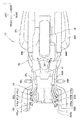
Fig. 2 is a view of the exhaust device taken alongarrow 2 inFig. 1 ; -
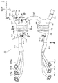
Fig. 3 is a plan view of the exhaust device provided to the motorcycle; -
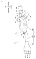
Fig. 4 is a left side view of the exhaust device taken alongarrow 4 inFig. 3 ; -
Fig. 5 is a cross-sectional view taken along line 5-5 inFig. 3 ; -
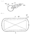
Fig. 6 is a cross-sectional view taken along line 6-6 inFig. 3 ; -
Fig. 7 is a cross-sectional view taken along line 7-7 inFig. 3 ; and -
Fig. 8 is a cross-sectional view taken along line 8-8 inFig. 3 . - Hereinafter, an embodiment of the invention will be explained in detail. In the drawings and the embodiment, the directions "up", "down", "front", "rear", "left", and "right" should be interpreted from the viewpoint of a rider who rides on a motorcycle respectively.
- As shown in
Fig. 1 , amotorcycle 10 is a saddle-ride-type vehicle where amain frame 13 which extends from ahead pipe 12 toward a rear of the vehicle, and apivot frame 18 which extends downward from themain frame 13 are mounted on avehicle body frame 11. Anengine 14 is suspended from thevehicle body frame 11. A frontwheel steering portion 12 including afront wheel 15 is mounted on thehead pipe 12 in a steerable manner. A rearwheel suspension portion 22 is supported on thepivot frame 18 in a swingable manner. Aseat 17 is mounted on thevehicle body frame 11 between thefront wheel 15 and therear wheel 16, and an occupant rides on the vehicle in a state where the rider straddles theseat 17. - The front
wheel steering portion 21 which is mounted on thevehicle body frame 11 in a steerable manner includes, as main constitutional elements thereof: afront fork 24 which is mounted on thehead pipe 12 in a rotatable manner; thefront wheel 15 which is supported on a lower end of thefront fork 24; and asteering handlebar 25 which is mounted on an upper end of thefront fork 24. The rearwheel suspension portion 22 includes: aswing arm 19 which extends toward the rear of the vehicle from thepivot frame 18, and therear wheel 16 which is supported on a rear end portion of theswing arm 19. - A
vehicle body cover 30 which covers a vehicle body includes: afront cowl 31; left and rightfront side cowls 32L, 32R (only thefront side cowl 32L on the viewer's side in the drawing is shown) which extend toward the rear of the vehicle from thefront cowl 31 up to an upper side of theengine 14; an undercowl 33 which covers theengine 14 from below and anexhaust device 40; and left andright protectors protector 34L on the viewer's side in the drawing is shown) which are disposed continuously with a rear side of the undercowl 33 and cover theexhaust device 40. - Left and
right trunks rear wheel 16 at a rear portion of the vehicle, and arear trunk 37 is arranged above the left andright trunks front fender 38 for preventing sticking of mud splashed by thefront wheel 15 is mounted on thefront fork 24. - As shown in
Fig. 2 , theengine 14 mounted on themotorcycle 10 is a horizontally opposed six-cylinder engine. Theexhaust device 40 is provided to the multi-cylinder engine. In an underside view of the vehicle (as viewed from below),cylinder portions engine 14 are disposed on left and right sides in the lateral direction of the vehicle.Exhaust pipes 41 La, 41 Lb, 41 Lc, 41 Ra, 41 Rb, 41 Rc for discharging an exhaust gas extend from lower surfaces 42Lb, 42Rb of thecylinder portions - Left and right merging
portions right exhaust pipes 41 L (41 La, 41 Lb, 41 Lc), 41 R (41 Ra, 41 Rb, 41 Rc) respectively, andmufflers portions - Foot rests 46L, 46R on which an occupant places his or her feet are mounted on the
pivot frame 18, and amain stand 47 is mounted on thepivot frame 18. - As shown in
Fig. 3 , the pair of left andright exhaust pipes right exhaust pipes portion catalyst portions side oxygen sensor right exhaust pipes catalysts - Downstream of the
catalysts right exhaust pipes portion mufflers Fig. 2 ) and the other end thereof extending to a connectingpipe 54 which connects the pair of left andright exhaust pipes side oxygen sensor 52 is provided on a downstream side of the right branchingportion 55R out of the pair of left and right branchingportions portions portions portions portions temperature sensor 53 is further provided to the branchingportion 55R, upstream of the downstream-side oxygen sensor 52. Hereinafter, the downstream-side oxygen sensor 52 is simply referred to as anoxygen sensor 52. - As shown in
Fig. 4 , the mergingpotion 43L is provided at a downstream part of theexhaust pipe 41 L. The mergingportion 43L includes: a first mergingportion 61 L to which threeexhaust pipes 41 La, 41 Lb, 41 Lc are merged together and whose diameter is decreased so as to decrease a cross-sectional area of theexhaust pipe 41 L; asecond merging portion 62L which is connected to a downstream end of the first mergingportion 61 L, has a constant cross-sectional area and extends toward the rear of the vehicle; athird merging portion 63L which is connected to a downstream end of thesecond merging portion 62L, has a diameter which enlarges in the direction of exhaust gas flow so as to increase the cross-sectional area of theexhaust pipe 41 L and eventually has a cross-sectional area larger than respective cross-sectional areas of the first mergingportion 61 L and thesecond merging portion 62L, and accommodates thecatalyst 48L (seeFig. 2 ) therein; and the branchingportion 55L which is formed contiguously with the mergingportion 43L. - A first
side extending portion 65L which extends toward the rear of the vehicle and a secondside extending portion 66L which extends laterally inward are provided at a downstream side of the branchingportion 55L respectively. The connectingpipe 54 is connected to the secondside extending portion 66L. Returning toFig. 3 , the secondside extending portion 66L and the connectingpipe 54 are formed integrally with each other in this embodiment. However, the second side extending portion and the connecting pipe may be formed separately from each other without any problems. - The connecting
pipe 54 is arranged such that the connectingpipe 54 is disposed below theoxygen sensor 52 and overlaps with theoxygen sensor 52 in the longitudinal (front-rear) direction of the vehicle. An exhaust pipe stay 69 provided for mounting theexhaust pipe 41 L on the vehicle body frame extends upward from thethird merging portion 63L. - The right branching portion is arranged so as to be in lateral symmetry with the left branching potion with respect to a longitudinal centreline of the vehicle (that is, a centreline extending in the front-rear direction), and so detailed explanation of the structure of the right branching portion is omitted.
- Returning to
Fig. 3 , theoxygen sensor 52 is provided on the right firstside extending portion 65R. - As shown in
Fig. 5 , an upstream-side boss 67R is mounted on thesecond merging portion 62R which forms the mergingportion 43R, and the upstream-side oxygen sensor 51 R is mounted on the upstream-side boss 67R. The upstream-side oxygen sensor 51 R is arranged in an inclined manner with respect to the horizontal direction such that an axis 51 RX of the upstream-side oxygen sensor is directed laterally inwards. - The right
second merging portion 62R including the upstream-side oxygen sensor is arranged so as to be laterally symmetric with the left second merging portion with respect to a longitudinal centreline of the vehicle, and so detailed explanation of the structure of the right second merging portion is omitted. - As shown in
Fig. 6 , thethird merging portion 63R which forms the merging portion is formed from anupper half body 75 and alower half body 76 respectively, which each have a generally semi-elliptical shape and vertically abut each other. Thecatalyst 48R for purifying an exhaust gas is accommodated in the third merging portion 63. - The left third merging portion is arranged so as to be laterally symmetric with the right third merging portion with respect to a longitudinal centreline of the vehicle, and so detailed explanation of the structure of the left third merging portion is omitted.
- As shown in
Fig. 7 , the branchingportion 55R which extends contiguously from thethird merging portion 63R includes: aceiling wall 71 which is provided at a downstream side of thecatalyst 48R; abottom wall 72 which is arranged to face theceiling wall 71 in an opposed manner; and arear wall 73 which extends between theceiling wall 71 and thebottom wall 72 and faces the rear of the vehicle. - A
temperature sensor boss 58 is mounted on therear wall 73, and thetemperature sensor 53 is mounted on thetemperature sensor boss 58. Alongitudinal axis 53X of thetemperature sensor 53 extends so as to be directed toward the rear of the vehicle. - The left branching portion and the right branching portion are arranged so as to be laterally symmetric with respect to a longitudinal centreline of the vehicle, and so a detailed explanation of the structure of the left branching portion is omitted.
- As shown in
Fig. 8 , anoxygen sensor boss 68 is mounted on the firstside extending portion 65R of the branchingportion 55R, and theoxygen sensor 52 is mounted on theoxygen sensor boss 68. Alongitudinal axis 52X of theoxygen sensor 52 extends so as to be directed laterally inwardly with respect to the vehicle. That is, anupper end 52a of theoxygen sensor 52 is directed laterally inwardly. - The
right protector 34R which covers theexhaust pipe 41 is arranged laterally outside the firstside extending portion 65R of theexhaust pipe 41. That is, theright protector 34R covers theright exhaust pipe 41 R when viewed in a side view of the vehicle. - The
left protector 34L (seeFig. 1 ) which covers theexhaust pipe 41 is arranged on a left side of the vehicle. Theleft protector 34L and the right protector have a symmetrical structure with respect to a longitudinal centreline of the vehicle, and so a detailed explanation of the structure of theleft protector 34L is omitted. - The manner of operation of the above-mentioned exhaust device of the motorcycle will now be described.
- Referring also to
Fig. 3 ,Fig. 7 andFig. 8 , on a downstream side of thecatalysts portions right exhaust pipes oxygen sensor 52 is provided to one side (the rear side in the longitudinal direction of the vehicle) of theright exhaust pipe 41. - An exhaust gas passes through the
catalysts portions exhaust pipe 41, and reaches the pair of left and right branchingportions portions portions portions oxygen sensor 52 provided to one side (the rear side in the longitudinal direction of the vehicle) of theright exhaust pipe 41 on the downstream side of the branchingportions catalyst 48R can be determined more accurately. - The
temperature sensor 53 is provided to theright branching portion 55R upstream of theoxygen sensor 52. Thetemperature sensor 53 is arranged at a position closer to thecatalyst 48R than theoxygen sensor 52 is, and hence, a reaction heat generated by a chemical reaction of thecatalyst 48R can be detected more accurately. The degree of activation of thecatalyst 48R and a state of thecatalyst 48R can be further accurately determined not only by theoxygen sensor 52 but also by thetemperature sensor 53. Since an activation state of thecatalyst 48R can be determined more accurately, a reduction in the size of thecatalyst 48R can be achieved. - In this embodiment, the oxygen sensor and the temperature sensor are provided at the downstream side of the right exhaust pipe, and neither the oxygen sensor nor the temperature sensor are provided on the downstream side of the left exhaust pipe. However, the oxygen sensor and the temperature sensor may be provided on the downstream side of the left exhaust pipe without any problems. Alternatively, both the oxygen sensor and the temperature sensor may be provided on the downstream sides of both the left and right exhaust pipes. That is, the oxygen sensor and the temperature sensor may be arranged as desired.
- Referring also to
Fig. 1 andFig. 8 , theupper end 52a of theoxygen sensor 52 is directed laterally inwardly, and overlaps with the left and right protectors 35L, 35R which cover the pair of left andright exhaust pipes oxygen sensor 52 is arranged so that it is not exposed to the outside in the lateral direction of the vehicle, and hence, it is possible to provide a structure which is minimally cooled by an external environment such as rain or a traveling wind. As a result, a state of thecatalysts - Returning to
Fig. 4 , the connectingpipe 54 is arranged such that the connectingpipe 54 is below theoxygen sensor 52 and overlaps with theoxygen sensor 52 in a longitudinal direction of the vehicle. A traveling wind which flows below the vehicle, water splashed up by the front wheel 15 (seeFig. 1 ) or the like will thus tend to hit the connectingpipe 54 arranged below theoxygen sensor 52, and hence, a traveling wind, water or the like minimally hits theoxygen sensor 52. Accordingly, theoxygen sensor 52 is minimally cooled by an external environment such as a traveling wind or water, and so theoxygen sensor 52 can determine a state of thecatalysts - Although the invention is applied to a motorcycle in this embodiment, the invention is also applicable to a three-wheeled vehicle and may be applied to vehicles in general without any problems.
- The invention is preferably applied to a motorcycle where an oxygen sensor is provided downstream of a catalyst in an exhaust device of an engine.
Claims (4)
- An exhaust device for a motorcycle comprising: a pair of left and right exhaust pipes (41 L, 41 R) for discharging an exhaust gas from a multi-cylinder engine (14); and a muffler (44L, 44R) connected to a downstream side of the exhaust pipe (41 L, 41 R), the muffler (44L, 44R) being provided for reducing an exhaust noise and for discharging an exhaust gas to the outside, wherein
the pair of left and right exhaust pipes (41 L, 41 R) includes a merging portion (43L, 43R) for merging exhaust pipes from respective cylinders respectively, and a catalyst (48L, 48R) for purifying an exhaust gas is provided in the merging portion (43L, 43R) respectively, and
the pair of left and right exhaust pipes (41 L, 41 R) includes, downstream of the catalyst (48L, 48R), a branching portion (55L, 55R) which has one side thereof extending to the muffler (44L, 44R) and the other side thereof extending to a connecting pipe (54) which connects the pair of left and right exhaust pipes (41 L, 41 R) to each other, and
an oxygen sensor (52) is provided at a downstream side of said one side of one of the left and right branching portions (55L, 55R), whereby
an exhaust gas is stirred in a rear portion of the merging portion (43L, 43R) and the branching portion (55L, 55R). - An exhaust device for a motorcycle according to claim 1, wherein a temperature sensor (53) is provided on the branching portion (55L, 55R) upstream of the oxygen sensor (52).
- An exhaust device for a motorcycle according to claim 1 or claim 2, wherein an upper end of the oxygen sensor (52) is directed laterally inwardly, and overlaps with left and right protectors (34L, 34R) which cover the pair of left and right exhaust pipes (41 L, 41 R) as viewed in a side view of the vehicle.
- An exhaust device for a motorcycle according to any one of claims 1 to 3, wherein the connecting pipe (54) is arranged below the oxygen sensor (52) and is arranged so as to overlap with the oxygen sensor (52) in a longitudinal direction of the vehicle.
Applications Claiming Priority (1)
| Application Number | Priority Date | Filing Date | Title |
|---|---|---|---|
| JP2015035093A JP6266549B2 (en) | 2015-02-25 | 2015-02-25 | Motorcycle exhaust system |
Publications (2)
| Publication Number | Publication Date |
|---|---|
| EP3061932A1 true EP3061932A1 (en) | 2016-08-31 |
| EP3061932B1 EP3061932B1 (en) | 2017-12-13 |
Family
ID=55486483
Family Applications (1)
| Application Number | Title | Priority Date | Filing Date |
|---|---|---|---|
| EP16156758.1A Active EP3061932B1 (en) | 2015-02-25 | 2016-02-22 | Exhaust device of motorcycle |
Country Status (3)
| Country | Link |
|---|---|
| US (1) | US9708963B2 (en) |
| EP (1) | EP3061932B1 (en) |
| JP (1) | JP6266549B2 (en) |
Cited By (1)
| Publication number | Priority date | Publication date | Assignee | Title |
|---|---|---|---|---|
| EP3779138A4 (en) * | 2018-03-29 | 2021-04-28 | Honda Motor Co., Ltd. | EXHAUST SYSTEM FOR INTERNAL COMBUSTION ENGINE |
Families Citing this family (6)
| Publication number | Priority date | Publication date | Assignee | Title |
|---|---|---|---|---|
| WO2016152542A1 (en) * | 2015-03-24 | 2016-09-29 | 本田技研工業株式会社 | Saddle-riding-type vehicle exhaust device |
| DE102017212307A1 (en) * | 2017-07-19 | 2019-01-24 | Bayerische Motoren Werke Aktiengesellschaft | Exhaust system for an internal combustion engine |
| JP6790034B2 (en) * | 2018-09-11 | 2020-11-25 | 本田技研工業株式会社 | Exhaust pipe structure of in-line 4-cylinder internal combustion engine |
| JP7263718B2 (en) * | 2018-09-13 | 2023-04-25 | スズキ株式会社 | Exhaust system and vehicle |
| JP2025058517A (en) * | 2023-09-28 | 2025-04-09 | カワサキモータース株式会社 | Saddle riding vehicle |
| JP7777623B2 (en) * | 2024-03-29 | 2025-11-28 | 本田技研工業株式会社 | exhaust system |
Citations (6)
| Publication number | Priority date | Publication date | Assignee | Title |
|---|---|---|---|---|
| JPS6245924A (en) * | 1985-08-26 | 1987-02-27 | Yamaha Motor Co Ltd | Exhaust pipe device of multiple cylinder engine for motor cycle |
| JP2003314383A (en) | 2002-04-23 | 2003-11-06 | Hitachi Unisia Automotive Ltd | Catalyst activity control device for internal combustion engine |
| EP1400666A1 (en) * | 2002-09-21 | 2004-03-24 | J. Eberspächer GmbH Co. KG | Exhaust System for an Internal Combustion Engine |
| JP2005220814A (en) * | 2004-02-05 | 2005-08-18 | Suzuki Motor Corp | Motorcycle exhaust system |
| EP1900624A1 (en) * | 2006-09-14 | 2008-03-19 | Yamaha Hatsudoki Kabushiki Kaisha | Motorcycle with exhaust pipe comprising an oxygen concentration sensor |
| JP2008138646A (en) * | 2006-12-05 | 2008-06-19 | Honda Motor Co Ltd | Exhaust system |
Family Cites Families (17)
| Publication number | Priority date | Publication date | Assignee | Title |
|---|---|---|---|---|
| JPS57135243A (en) * | 1981-02-17 | 1982-08-20 | Fuji Heavy Ind Ltd | Air-fuel ratio controller |
| JPH0625539B2 (en) * | 1983-07-15 | 1994-04-06 | ヤマハ発動機株式会社 | Exhaust gas purification device for motorcycles |
| JP2966554B2 (en) * | 1991-02-22 | 1999-10-25 | ヤマハ発動機株式会社 | O2 sensor arrangement structure for exhaust system for motorcycle |
| JP3046435B2 (en) * | 1991-09-11 | 2000-05-29 | ヤマハ発動機株式会社 | Motorcycle oxygen sensor protection device |
| US5325664A (en) * | 1991-10-18 | 1994-07-05 | Honda Giken Kogyo Kabushiki Kaisha | System for determining deterioration of catalysts of internal combustion engines |
| JP3026684B2 (en) * | 1992-07-08 | 2000-03-27 | ヤマハ発動機株式会社 | Exhaust gas purification device for vehicle engine |
| JP2830668B2 (en) * | 1992-12-29 | 1998-12-02 | トヨタ自動車株式会社 | Exhaust gas purification device for internal combustion engine |
| JP3378474B2 (en) * | 1997-08-06 | 2003-02-17 | トヨタ自動車株式会社 | Exhaust manifold of internal combustion engine |
| DE19812090C2 (en) * | 1998-03-19 | 2000-03-09 | Daimler Chrysler Ag | Multi-cylinder piston internal combustion engine with at least two cylinder banks |
| JP4057145B2 (en) * | 1998-05-29 | 2008-03-05 | 本田技研工業株式会社 | Exhaust gas sensor arrangement structure for motorcycles |
| JP4643084B2 (en) * | 2001-09-17 | 2011-03-02 | ヤマハ発動機株式会社 | Exhaust sensor arrangement structure for motorcycles |
| WO2007012952A1 (en) * | 2005-07-29 | 2007-02-01 | Toyota Jidosha Kabushiki Kaisha | Exhaust purification system for internal combustion engine |
| JP2007162653A (en) * | 2005-12-16 | 2007-06-28 | Kawasaki Heavy Ind Ltd | Vehicle exhaust system and motorcycle equipped with the vehicle exhaust system |
| JP2010255514A (en) * | 2009-04-24 | 2010-11-11 | Honda Motor Co Ltd | Exhaust device for saddle riding type vehicle |
| JP5644124B2 (en) * | 2010-02-02 | 2014-12-24 | スズキ株式会社 | Exhaust gas sensor mounting structure for motorcycles |
| JP6168853B2 (en) * | 2013-05-31 | 2017-07-26 | 本田技研工業株式会社 | Motorcycle exhaust system |
| JP2015036519A (en) * | 2013-08-12 | 2015-02-23 | スズキ株式会社 | Driving control device of exhaust air sensor heater |
-
2015
- 2015-02-25 JP JP2015035093A patent/JP6266549B2/en not_active Expired - Fee Related
-
2016
- 2016-02-22 EP EP16156758.1A patent/EP3061932B1/en active Active
- 2016-02-23 US US15/051,644 patent/US9708963B2/en active Active
Patent Citations (6)
| Publication number | Priority date | Publication date | Assignee | Title |
|---|---|---|---|---|
| JPS6245924A (en) * | 1985-08-26 | 1987-02-27 | Yamaha Motor Co Ltd | Exhaust pipe device of multiple cylinder engine for motor cycle |
| JP2003314383A (en) | 2002-04-23 | 2003-11-06 | Hitachi Unisia Automotive Ltd | Catalyst activity control device for internal combustion engine |
| EP1400666A1 (en) * | 2002-09-21 | 2004-03-24 | J. Eberspächer GmbH Co. KG | Exhaust System for an Internal Combustion Engine |
| JP2005220814A (en) * | 2004-02-05 | 2005-08-18 | Suzuki Motor Corp | Motorcycle exhaust system |
| EP1900624A1 (en) * | 2006-09-14 | 2008-03-19 | Yamaha Hatsudoki Kabushiki Kaisha | Motorcycle with exhaust pipe comprising an oxygen concentration sensor |
| JP2008138646A (en) * | 2006-12-05 | 2008-06-19 | Honda Motor Co Ltd | Exhaust system |
Cited By (1)
| Publication number | Priority date | Publication date | Assignee | Title |
|---|---|---|---|---|
| EP3779138A4 (en) * | 2018-03-29 | 2021-04-28 | Honda Motor Co., Ltd. | EXHAUST SYSTEM FOR INTERNAL COMBUSTION ENGINE |
Also Published As
| Publication number | Publication date |
|---|---|
| JP2016156330A (en) | 2016-09-01 |
| US9708963B2 (en) | 2017-07-18 |
| US20160245147A1 (en) | 2016-08-25 |
| JP6266549B2 (en) | 2018-01-24 |
| EP3061932B1 (en) | 2017-12-13 |
Similar Documents
| Publication | Publication Date | Title |
|---|---|---|
| EP3061932B1 (en) | Exhaust device of motorcycle | |
| EP3276149B1 (en) | Motorcycle | |
| US7882700B2 (en) | Exhaust pipe structure | |
| EP1975382B1 (en) | Exhaust system for motorcycle | |
| JP6454578B2 (en) | Motorcycle | |
| EP3064722B1 (en) | Exhaust device for engine | |
| EP3002190B1 (en) | Saddle-type ride vehicle | |
| US7644800B2 (en) | Motorcycle exhaust structure | |
| JP2017214904A (en) | Exhaust gas sensor arrangement structure | |
| EP2835308A1 (en) | Front cowl stay attachment structure for saddle-ride type vehicle | |
| US8622168B2 (en) | Motorcycle exhaust system structure including a resonator provided to an exhaust pipe | |
| JP6620677B2 (en) | Exhaust gas sensor layout | |
| US20170183994A1 (en) | Exhaust device structure for rocking vehicle | |
| JP6610438B2 (en) | Exhaust gas sensor layout | |
| JP2018115652A (en) | Exhaust gas sensor layout | |
| JP6623925B2 (en) | Arrangement structure of exhaust gas sensor | |
| WO2019043869A1 (en) | Exhaust device for saddled vehicles | |
| JP2019015277A (en) | Exhaust gas sensor arrangement structure and motor cycle | |
| EP3779138B1 (en) | Exhaust device for internal combustion engine | |
| EP2436895A1 (en) | Exhaust apparatus for motorcycle | |
| US7367419B2 (en) | Oxygen concentration sensor for a saddle ride type all-terrain vehicle | |
| JP4670996B1 (en) | Engine intake system passage structure | |
| JP6730413B2 (en) | Motorcycle | |
| JP2021021347A (en) | Exhaust device of engine | |
| CN110461695A (en) | straddle vehicle |
Legal Events
| Date | Code | Title | Description |
|---|---|---|---|
| PUAI | Public reference made under article 153(3) epc to a published international application that has entered the european phase |
Free format text: ORIGINAL CODE: 0009012 |
|
| 17P | Request for examination filed |
Effective date: 20160222 |
|
| AK | Designated contracting states |
Kind code of ref document: A1 Designated state(s): AL AT BE BG CH CY CZ DE DK EE ES FI FR GB GR HR HU IE IS IT LI LT LU LV MC MK MT NL NO PL PT RO RS SE SI SK SM TR |
|
| AX | Request for extension of the european patent |
Extension state: BA ME |
|
| REG | Reference to a national code |
Ref country code: DE Ref legal event code: R079 Ref document number: 602016001038 Country of ref document: DE Free format text: PREVIOUS MAIN CLASS: F01N0001000000 Ipc: F01N0013000000 |
|
| GRAP | Despatch of communication of intention to grant a patent |
Free format text: ORIGINAL CODE: EPIDOSNIGR1 |
|
| STAA | Information on the status of an ep patent application or granted ep patent |
Free format text: STATUS: GRANT OF PATENT IS INTENDED |
|
| RIC1 | Information provided on ipc code assigned before grant |
Ipc: F01N 13/10 20100101ALI20170612BHEP Ipc: F01N 1/00 20060101ALI20170612BHEP Ipc: F01N 13/00 20100101AFI20170612BHEP |
|
| INTG | Intention to grant announced |
Effective date: 20170703 |
|
| GRAS | Grant fee paid |
Free format text: ORIGINAL CODE: EPIDOSNIGR3 |
|
| GRAA | (expected) grant |
Free format text: ORIGINAL CODE: 0009210 |
|
| STAA | Information on the status of an ep patent application or granted ep patent |
Free format text: STATUS: THE PATENT HAS BEEN GRANTED |
|
| REG | Reference to a national code |
Ref country code: GB Ref legal event code: FG4D |
|
| REG | Reference to a national code |
Ref country code: AT Ref legal event code: REF Ref document number: 954609 Country of ref document: AT Kind code of ref document: T Effective date: 20171215 Ref country code: CH Ref legal event code: EP |
|
| REG | Reference to a national code |
Ref country code: IE Ref legal event code: FG4D |
|
| REG | Reference to a national code |
Ref country code: DE Ref legal event code: R096 Ref document number: 602016001038 Country of ref document: DE |
|
| REG | Reference to a national code |
Ref country code: FR Ref legal event code: PLFP Year of fee payment: 3 |
|
| REG | Reference to a national code |
Ref country code: NL Ref legal event code: MP Effective date: 20171213 |
|
| PG25 | Lapsed in a contracting state [announced via postgrant information from national office to epo] |
Ref country code: SE Free format text: LAPSE BECAUSE OF FAILURE TO SUBMIT A TRANSLATION OF THE DESCRIPTION OR TO PAY THE FEE WITHIN THE PRESCRIBED TIME-LIMIT Effective date: 20171213 Ref country code: FI Free format text: LAPSE BECAUSE OF FAILURE TO SUBMIT A TRANSLATION OF THE DESCRIPTION OR TO PAY THE FEE WITHIN THE PRESCRIBED TIME-LIMIT Effective date: 20171213 Ref country code: NO Free format text: LAPSE BECAUSE OF FAILURE TO SUBMIT A TRANSLATION OF THE DESCRIPTION OR TO PAY THE FEE WITHIN THE PRESCRIBED TIME-LIMIT Effective date: 20180313 |
|
| REG | Reference to a national code |
Ref country code: AT Ref legal event code: MK05 Ref document number: 954609 Country of ref document: AT Kind code of ref document: T Effective date: 20171213 |
|
| PG25 | Lapsed in a contracting state [announced via postgrant information from national office to epo] |
Ref country code: BG Free format text: LAPSE BECAUSE OF FAILURE TO SUBMIT A TRANSLATION OF THE DESCRIPTION OR TO PAY THE FEE WITHIN THE PRESCRIBED TIME-LIMIT Effective date: 20180313 Ref country code: HR Free format text: LAPSE BECAUSE OF FAILURE TO SUBMIT A TRANSLATION OF THE DESCRIPTION OR TO PAY THE FEE WITHIN THE PRESCRIBED TIME-LIMIT Effective date: 20171213 Ref country code: GR Free format text: LAPSE BECAUSE OF FAILURE TO SUBMIT A TRANSLATION OF THE DESCRIPTION OR TO PAY THE FEE WITHIN THE PRESCRIBED TIME-LIMIT Effective date: 20180314 Ref country code: LV Free format text: LAPSE BECAUSE OF FAILURE TO SUBMIT A TRANSLATION OF THE DESCRIPTION OR TO PAY THE FEE WITHIN THE PRESCRIBED TIME-LIMIT Effective date: 20171213 Ref country code: RS Free format text: LAPSE BECAUSE OF FAILURE TO SUBMIT A TRANSLATION OF THE DESCRIPTION OR TO PAY THE FEE WITHIN THE PRESCRIBED TIME-LIMIT Effective date: 20171213 |
|
| PG25 | Lapsed in a contracting state [announced via postgrant information from national office to epo] |
Ref country code: NL Free format text: LAPSE BECAUSE OF FAILURE TO SUBMIT A TRANSLATION OF THE DESCRIPTION OR TO PAY THE FEE WITHIN THE PRESCRIBED TIME-LIMIT Effective date: 20171213 |
|
| PG25 | Lapsed in a contracting state [announced via postgrant information from national office to epo] |
Ref country code: EE Free format text: LAPSE BECAUSE OF FAILURE TO SUBMIT A TRANSLATION OF THE DESCRIPTION OR TO PAY THE FEE WITHIN THE PRESCRIBED TIME-LIMIT Effective date: 20171213 Ref country code: CY Free format text: LAPSE BECAUSE OF FAILURE TO SUBMIT A TRANSLATION OF THE DESCRIPTION OR TO PAY THE FEE WITHIN THE PRESCRIBED TIME-LIMIT Effective date: 20171213 Ref country code: ES Free format text: LAPSE BECAUSE OF FAILURE TO SUBMIT A TRANSLATION OF THE DESCRIPTION OR TO PAY THE FEE WITHIN THE PRESCRIBED TIME-LIMIT Effective date: 20171213 Ref country code: CZ Free format text: LAPSE BECAUSE OF FAILURE TO SUBMIT A TRANSLATION OF THE DESCRIPTION OR TO PAY THE FEE WITHIN THE PRESCRIBED TIME-LIMIT Effective date: 20171213 Ref country code: SK Free format text: LAPSE BECAUSE OF FAILURE TO SUBMIT A TRANSLATION OF THE DESCRIPTION OR TO PAY THE FEE WITHIN THE PRESCRIBED TIME-LIMIT Effective date: 20171213 |
|
| PG25 | Lapsed in a contracting state [announced via postgrant information from national office to epo] |
Ref country code: AT Free format text: LAPSE BECAUSE OF FAILURE TO SUBMIT A TRANSLATION OF THE DESCRIPTION OR TO PAY THE FEE WITHIN THE PRESCRIBED TIME-LIMIT Effective date: 20171213 Ref country code: IS Free format text: LAPSE BECAUSE OF FAILURE TO SUBMIT A TRANSLATION OF THE DESCRIPTION OR TO PAY THE FEE WITHIN THE PRESCRIBED TIME-LIMIT Effective date: 20180413 Ref country code: RO Free format text: LAPSE BECAUSE OF FAILURE TO SUBMIT A TRANSLATION OF THE DESCRIPTION OR TO PAY THE FEE WITHIN THE PRESCRIBED TIME-LIMIT Effective date: 20171213 Ref country code: SM Free format text: LAPSE BECAUSE OF FAILURE TO SUBMIT A TRANSLATION OF THE DESCRIPTION OR TO PAY THE FEE WITHIN THE PRESCRIBED TIME-LIMIT Effective date: 20171213 Ref country code: PL Free format text: LAPSE BECAUSE OF FAILURE TO SUBMIT A TRANSLATION OF THE DESCRIPTION OR TO PAY THE FEE WITHIN THE PRESCRIBED TIME-LIMIT Effective date: 20171213 |
|
| REG | Reference to a national code |
Ref country code: DE Ref legal event code: R097 Ref document number: 602016001038 Country of ref document: DE |
|
| PG25 | Lapsed in a contracting state [announced via postgrant information from national office to epo] |
Ref country code: MC Free format text: LAPSE BECAUSE OF FAILURE TO SUBMIT A TRANSLATION OF THE DESCRIPTION OR TO PAY THE FEE WITHIN THE PRESCRIBED TIME-LIMIT Effective date: 20171213 |
|
| PLBE | No opposition filed within time limit |
Free format text: ORIGINAL CODE: 0009261 |
|
| STAA | Information on the status of an ep patent application or granted ep patent |
Free format text: STATUS: NO OPPOSITION FILED WITHIN TIME LIMIT |
|
| 26N | No opposition filed |
Effective date: 20180914 |
|
| REG | Reference to a national code |
Ref country code: IE Ref legal event code: MM4A |
|
| REG | Reference to a national code |
Ref country code: BE Ref legal event code: MM Effective date: 20180228 |
|
| PG25 | Lapsed in a contracting state [announced via postgrant information from national office to epo] |
Ref country code: LU Free format text: LAPSE BECAUSE OF NON-PAYMENT OF DUE FEES Effective date: 20180222 Ref country code: DK Free format text: LAPSE BECAUSE OF FAILURE TO SUBMIT A TRANSLATION OF THE DESCRIPTION OR TO PAY THE FEE WITHIN THE PRESCRIBED TIME-LIMIT Effective date: 20171213 |
|
| PG25 | Lapsed in a contracting state [announced via postgrant information from national office to epo] |
Ref country code: IE Free format text: LAPSE BECAUSE OF NON-PAYMENT OF DUE FEES Effective date: 20180222 |
|
| PG25 | Lapsed in a contracting state [announced via postgrant information from national office to epo] |
Ref country code: SI Free format text: LAPSE BECAUSE OF FAILURE TO SUBMIT A TRANSLATION OF THE DESCRIPTION OR TO PAY THE FEE WITHIN THE PRESCRIBED TIME-LIMIT Effective date: 20171213 Ref country code: BE Free format text: LAPSE BECAUSE OF NON-PAYMENT OF DUE FEES Effective date: 20180228 |
|
| PGFP | Annual fee paid to national office [announced via postgrant information from national office to epo] |
Ref country code: FR Payment date: 20190111 Year of fee payment: 4 |
|
| REG | Reference to a national code |
Ref country code: CH Ref legal event code: PL |
|
| REG | Reference to a national code |
Ref country code: DE Ref legal event code: R084 Ref document number: 602016001038 Country of ref document: DE |
|
| PG25 | Lapsed in a contracting state [announced via postgrant information from national office to epo] |
Ref country code: CH Free format text: LAPSE BECAUSE OF NON-PAYMENT OF DUE FEES Effective date: 20190228 Ref country code: LI Free format text: LAPSE BECAUSE OF NON-PAYMENT OF DUE FEES Effective date: 20190228 |
|
| PG25 | Lapsed in a contracting state [announced via postgrant information from national office to epo] |
Ref country code: MT Free format text: LAPSE BECAUSE OF NON-PAYMENT OF DUE FEES Effective date: 20180222 |
|
| PG25 | Lapsed in a contracting state [announced via postgrant information from national office to epo] |
Ref country code: TR Free format text: LAPSE BECAUSE OF FAILURE TO SUBMIT A TRANSLATION OF THE DESCRIPTION OR TO PAY THE FEE WITHIN THE PRESCRIBED TIME-LIMIT Effective date: 20171213 |
|
| PG25 | Lapsed in a contracting state [announced via postgrant information from national office to epo] |
Ref country code: PT Free format text: LAPSE BECAUSE OF FAILURE TO SUBMIT A TRANSLATION OF THE DESCRIPTION OR TO PAY THE FEE WITHIN THE PRESCRIBED TIME-LIMIT Effective date: 20171213 |
|
| PG25 | Lapsed in a contracting state [announced via postgrant information from national office to epo] |
Ref country code: HU Free format text: LAPSE BECAUSE OF FAILURE TO SUBMIT A TRANSLATION OF THE DESCRIPTION OR TO PAY THE FEE WITHIN THE PRESCRIBED TIME-LIMIT; INVALID AB INITIO Effective date: 20160222 Ref country code: MK Free format text: LAPSE BECAUSE OF NON-PAYMENT OF DUE FEES Effective date: 20171213 Ref country code: LT Free format text: LAPSE BECAUSE OF FAILURE TO SUBMIT A TRANSLATION OF THE DESCRIPTION OR TO PAY THE FEE WITHIN THE PRESCRIBED TIME-LIMIT Effective date: 20171213 |
|
| PG25 | Lapsed in a contracting state [announced via postgrant information from national office to epo] |
Ref country code: AL Free format text: LAPSE BECAUSE OF FAILURE TO SUBMIT A TRANSLATION OF THE DESCRIPTION OR TO PAY THE FEE WITHIN THE PRESCRIBED TIME-LIMIT Effective date: 20171213 |
|
| GBPC | Gb: european patent ceased through non-payment of renewal fee |
Effective date: 20200222 |
|
| PG25 | Lapsed in a contracting state [announced via postgrant information from national office to epo] |
Ref country code: FR Free format text: LAPSE BECAUSE OF NON-PAYMENT OF DUE FEES Effective date: 20200229 Ref country code: GB Free format text: LAPSE BECAUSE OF NON-PAYMENT OF DUE FEES Effective date: 20200222 |
|
| PGFP | Annual fee paid to national office [announced via postgrant information from national office to epo] |
Ref country code: IT Payment date: 20240123 Year of fee payment: 9 |
|
| PG25 | Lapsed in a contracting state [announced via postgrant information from national office to epo] |
Ref country code: IT Free format text: LAPSE BECAUSE OF NON-PAYMENT OF DUE FEES Effective date: 20250222 |
|
| PGFP | Annual fee paid to national office [announced via postgrant information from national office to epo] |
Ref country code: DE Payment date: 20260121 Year of fee payment: 11 |