EP3061886A1 - Flashing arrangement for a window, window with a flashing arrangement, and method of providing a weather-tight transition between a window and surrounding roofing with such a flashing arrangement - Google Patents
Flashing arrangement for a window, window with a flashing arrangement, and method of providing a weather-tight transition between a window and surrounding roofing with such a flashing arrangement Download PDFInfo
- Publication number
- EP3061886A1 EP3061886A1 EP15203050.8A EP15203050A EP3061886A1 EP 3061886 A1 EP3061886 A1 EP 3061886A1 EP 15203050 A EP15203050 A EP 15203050A EP 3061886 A1 EP3061886 A1 EP 3061886A1
- Authority
- EP
- European Patent Office
- Prior art keywords
- window
- hand
- roofing
- piece
- gutter
- Prior art date
- Legal status (The legal status is an assumption and is not a legal conclusion. Google has not performed a legal analysis and makes no representation as to the accuracy of the status listed.)
- Granted
Links
Images




Classifications
-
- E—FIXED CONSTRUCTIONS
- E04—BUILDING
- E04D—ROOF COVERINGS; SKY-LIGHTS; GUTTERS; ROOF-WORKING TOOLS
- E04D13/00—Special arrangements or devices in connection with roof coverings; Protection against birds; Roof drainage ; Sky-lights
- E04D13/14—Junctions of roof sheathings to chimneys or other parts extending above the roof
- E04D13/147—Junctions of roof sheathings to chimneys or other parts extending above the roof specially adapted for inclined roofs
-
- E—FIXED CONSTRUCTIONS
- E04—BUILDING
- E04D—ROOF COVERINGS; SKY-LIGHTS; GUTTERS; ROOF-WORKING TOOLS
- E04D13/00—Special arrangements or devices in connection with roof coverings; Protection against birds; Roof drainage ; Sky-lights
- E04D13/14—Junctions of roof sheathings to chimneys or other parts extending above the roof
- E04D13/147—Junctions of roof sheathings to chimneys or other parts extending above the roof specially adapted for inclined roofs
- E04D13/1473—Junctions of roof sheathings to chimneys or other parts extending above the roof specially adapted for inclined roofs specially adapted to the cross-section of the parts extending above the roof
- E04D13/1475—Junctions of roof sheathings to chimneys or other parts extending above the roof specially adapted for inclined roofs specially adapted to the cross-section of the parts extending above the roof wherein the parts extending above the roof have a generally rectangular cross-section
-
- E—FIXED CONSTRUCTIONS
- E04—BUILDING
- E04D—ROOF COVERINGS; SKY-LIGHTS; GUTTERS; ROOF-WORKING TOOLS
- E04D13/00—Special arrangements or devices in connection with roof coverings; Protection against birds; Roof drainage ; Sky-lights
- E04D13/02—Roof-covering aspects of dormer windows
-
- E—FIXED CONSTRUCTIONS
- E04—BUILDING
- E04D—ROOF COVERINGS; SKY-LIGHTS; GUTTERS; ROOF-WORKING TOOLS
- E04D13/00—Special arrangements or devices in connection with roof coverings; Protection against birds; Roof drainage ; Sky-lights
- E04D13/03—Sky-lights; Domes; Ventilating sky-lights
Definitions
- a flashing arrangement of the kind mentioned in the introduction which is furthermore characterized in that the gutter element and the apron element are each asymmetrical relative to the middle axis and are each provided with a shape adapted to accommodate the surrounding roofing, and that the gutter element comprises a middle gutter piece adapted to be connected to the frame of the window, a roofing-supporting piece providing the shape to accommodate the surrounding roofing, and a left-hand gutter side piece and a right-hand gutter side piece asymmetrical relative to each other.
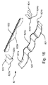
- the pieces of the apron element 82 may in principle be assembled in any suitable manner, but in a presently preferred embodiment as shown in Fig. 16 , the apron piece 821 is provided with engagement means, specifically in the form of folded flanges 821 a, 821 b, to cooperate with corresponding engagement means, specifically in the form of folded flanges 823a, 824b, of the left-hand and right-hand side pieces 823, 824, respectively.
Landscapes
- Engineering & Computer Science (AREA)
- Architecture (AREA)
- Civil Engineering (AREA)
- Structural Engineering (AREA)
- Roof Covering Using Slabs Or Stiff Sheets (AREA)
Abstract
Description
- The present invention relates to a flashing arrangement for a window having a supply condition and a mounted condition in an inclined roof comprising a roof construction, the flashing arrangement defining a middle axis adapted to be parallel to the inclination of the roof in the mounted condition and to form, in the mounted condition, a transition assembly between a frame of the window and a surrounding roofing having an asymmetrical profiling relative to the roof inclination, said flashing arrangement comprising a gutter element, an apron element and a plurality of intermediate side elements adapted to extend, in the mounted condition, between the gutter element and the apron element substantially in directions parallel to said middle axis. The invention furthermore relates to a window comprising a flashing arrangement, and to a method of providing a weather-tight transition between a window and a surrounding roofing.
- Such transition assemblies make it possible to achieve satisfactory connections between the window and the surroundings, namely typically with the interior, the roof construction and the surrounding roofing, from an installation point of view, including constructional, aesthetic, climate-proofing, and weather-tightening considerations.
- When installing windows in a roof, it is particularly essential that the transition to the surrounding roof is weather-tight. The position of the window in an inclined roof renders the installation conditions more complicated. This is applicable, whether the window and the window lining are intended for installation in a newly erected building, during complete refurbishing including several parts of the roof construction and/or the interior, or for renovation purposes involving replacement of as few components as possible.
- To meet this need, flashing arrangements are used for providing a substantially weather-tight transition between a roof penetrating building structure, i.e. typically the frame of a window, and the surrounding roofing material. Such flashing arrangements typically comprise a number of flashing elements to provide a flashing frame surrounding the roof penetrating building structure. At the bottom of the window, the flashing element normally comprises a plate or rail element to be attached to the window and an apron element adapted for resting on the outer surface of the roofing material. The apron element is important with regard to securing a well-fitting, stable and secure sealing of the joint between the window and the roof surface, particularly when using an undulated roofing material such as tiles. The apron shall ideally provide for an easy mounting procedure, which ensures that the apron is firmly and closely mounted onto the roofing and stays in this position for the entire lifetime of the flashing. In order to achieve this, the apron is traditionally made of a material, which is easy to bend, preferably by hand, and which has a relatively high weight and a low elasticity. At the sides and top of the roof penetrating structure, as seen in the inclination of the roof, the flashing elements typically comprise plate-shaped material of for instance metal.
- The installation process is particularly challenging in the case of roofs having a profiled roofing material such as undulated tiles. Such tiles are well-known in the art and a wide variety of profiles are available, such as pantiles, S-shaped pantiles, Roman tiles, double Roman tiles, interlocking tiles, Spanish tiles etc. Traditional tile materials are ceramics, clay and concrete, but also plastic and metal materials are known. Also roofing elements of for instance sheet metal imitating a number of interconnected tiles are commercially available. Common to all tiles is that the profiling comprises complementary interlocking border portions to engage with adjacent tiles. Hence, this entails that the profiling of the roofing is asymmetrical relative to the roof inclination.
- In combination with the requirements to satisfactory transitions as regards tightness and accurate positioning, the installation of a window and the connection to parts of the surrounding roofing present great challenges, and, in turn, the adaptation of the flashing arrangement to the roofing is normally troublesome and problematic.
- Applicant's Danish Patent No.
98982 EP patents Nos 1 038 078 B1 and1 019 598 B1 - With this background it is an object of the invention to provide a flashing arrangement which provides for a facilitated and improved installation process and an improved transition between a window and a surrounding roofing having an asymmetrical profiling.
- In a first aspect, this and further objects are met by a flashing arrangement of the kind mentioned in the introduction, which is furthermore characterized in that the gutter element and the apron element are each asymmetrical relative to the middle axis and are each provided with a shape adapted to accommodate the surrounding roofing, and that the gutter element comprises a middle gutter piece adapted to be connected to the frame of the window, a roofing-supporting piece providing the shape to accommodate the surrounding roofing, and a left-hand gutter side piece and a right-hand gutter side piece asymmetrical relative to each other.
- In this manner, a virtually fail-safe installation is ensured, and an excellent fit between the flashing arrangement and the roofing is provided. The provision of asymmetrically shaped flashing elements which furthermore provide for accommodation of the roofing has turned out to meet even the strictest demands to a flawless transition and inconspicuous appearance of the window in the roof in the mounted condition.
- Further embodiments and advantages are set forth in the dependent claims, and will be apparent from the accompanying description of preferred embodiments.
- In the following the invention will be described in further detail by means of examples of embodiments with reference to the schematic drawings, in which
-
Figs 1A and 1B are perspective views of a window in an embodiment of the invention; -
Fig. 2 is a view of the window ofFigs 1A and 1B , with two tiles indicated schematically; -
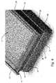
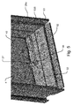
Figs 3 ,4 and5 are schematic, fragmentary perspective views, on a larger scale, of a window in one embodiment of the invention; -
Fig. 6 is a perspective view of details of the window in the embodiment ofFigs 3 ,4 and5 ; -
Fig. 7 is a perspective view, on a larger scale, of a detail ofFig. 6 ; -
Figs 8A and 8B are end views, on a larger scale, of the detail ofFig. 7 cooperating with a lining panel in two different installation situations; -
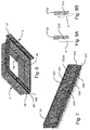
Figs 9A to 9B and10 are schematic perspective views of a window in a further embodiment of the invention; -
Fig. 9c is a cross-sectional fragmentary view along the line IX-IX inFig. 9A ; -
Fig. 11 is a schematic perspective view of an alternative window; -
Fig. 12A is a perspective view of an underfelt collar of the window ofFigs 9A-9B ,10 and 11 ; -
Fig. 12B is a perspective view of a prior art underfelt collar; -
Fig. 13 is a perspective view of a flashing arrangement of a still further embodiment of the window according to the invention; -
Fig. 14 is an exploded perspective view of the flashing arrangement shown inFig. 13 ; -
Figs 15 and16 are further exploded perspective views of details the flashing arrangement ofFig. 14 ; and -
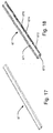
Figs 17 and 18 are perspective views, on a larger scale, of a detail of the flashing arrangement ofFig. 13 . - In
Figs 1A, 1B and2 , a window generally designated 1 is shown, in a position representing a mounted condition in an inclined roof with an undulated roofing material such as tiles represented by twotiles 10 inFig. 2 in an array below and an array above the window 1, respectively, as seen in the direction of inclination of the roof. The supporting roof construction is not shown but typically includes rafters, battens and counter-battens. Theframe 3 of the window 1 is connected to the supporting roof construction in any suitable manner, typically by means of a plurality of mounting brackets as is wellknown in the art. - The window 1 comprises a
sash 2 hingedly connected to a frame generally designated 3. Thesash 2 carries apane 4. - The
frame 3 is adapted to cooperate with a set of transition assemblies to form a transition to the interior, to the roof construction and to the surrounding roofing, respectively. - According to the present invention, the transition towards the interior of the building below the window is provided in that the set of transition assemblies comprises a transition assembly in the form of a
lining support arrangement 5 connected to theframe 3 and adapted to cooperate with a window lining including a set of lining panels 9 (cf.Figs 8A and 8B ) to be described in further detail below with particular reference toFigs 3 to 8B . - In the embodiment shown in
Figs 1A-1B and2 , the window 1 furthermore comprises another transition assembly in the supply condition to form a climate-proofing transition between the window 1 and the roof construction in the mounted condition. In the specific embodiments shown inFigs 9A-9C ,10 ,11 and12A , the other transition assembly comprises anunderfelt collar 7 connected to theframe 3 of the window 1 in the supply condition. Optionally, the other transition assembly also includes aninsulation element 6. - The transition assemblies described in the above are each the respective subject-matter of Applicant's co-pending patent applications filed on the same date as the present application. The contents thereof are incorporated by specific reference, and the parts of these transition assemblies will not be described in further detail than the below listing of elements:
- 2
- sash
21-24 sash members
25a sash hinge part
25b frame hinge part
25c hinge pin
26 fittings (at bottom sash member 22)
27 opening device
28a guiding console
28b first tap
28c pivot bushing
28d second tap
28e handle portion
29a connecting member
29b link
29c stay arm
29d apertures in stay arm
3 frame
3a first frame
31-34 first frame members
34a side frame covering
3b second frame
35-38 second frame members
381 bottom face
382 side face
4 pane
41 exterior pane sheet
42 interior pane sheet
5 lining support arrangement
51-54 lining support members
531 first frame engaging face/top surface
532 second frame engaging face/side surface
532a apertures
533 back side
534 first stepped portion
535 lining engagement portion/bead
536 second stepped portion
537 bottom surface - 6
- insulation element
- 7
- underfelt collar
71 frame engagement section/rim
72 roof structure engagement section - According to the present invention, a weather-tight transition between the window 1 and the surrounding
roofing 10 in the mounted condition is provided by means of a transition assembly comprising aflashing arrangement 8. This will be described in further detail with particular reference toFigs 2 andFigs 13 to 18 . - The flashing
assembly 8 is typically supplied separately from the window 1 and connected to theframe 3 of the window 1 and to theroofing 10 to attain the mounted condition during an installation process to be described in the following. - The flashing
arrangement 8 defines a middle axis x which is parallel to the inclination of the roof in the mounted condition and forms, in the mounted condition, a transition assembly between theframe 3 of the window 1 and the surroundingroofing 10 having an asymmetrical profiling relative to the roof inclination. The invention is in principle applicable to all kinds of profiled or undulated roofing, including pantiles, S-shaped pantiles, Roman tiles, double Roman tiles, interlocking tiles, Spanish tiles etc. and of any material including ceramics, clay and concrete, but also plastic and metal materials, and to roofing elements of for instance sheet metal imitating a number of interconnected tiles. Common to all such tiles is that the profiling comprises complementary interlocking border portions to engage with adjacent tiles and consequently the profiling of the roofing is asymmetrical relative to the roof inclination. In the embodiment shown, the flashingarrangement 8 is adapted to a roofing of pantiles having in a manner known per se a dishing portion forming a valley and a roll portion forming an apex at the right-hand border of eachtile 10, adapted to overlie the left-hand border of the neighbouring tile. - The flashing
arrangement 8 comprising agutter element 81, anapron element 82 and a plurality of intermediate side elements 83-87 adapted to extend, in the mounted condition, between thegutter element 81 and theapron element 82 substantially in directions parallel to the middle axis x. As indicated inFig. 2 , thegutter element 81 and theapron element 82 are each asymmetrical relative to the middle axis x and are each provided with a shape adapted to accommodate the surroundingroofing 10. - In the embodiment shown, the
gutter element 81 comprises amiddle gutter piece 811 adapted to be connected to theframe 3 of the window 1, a roofing-supportingpiece 812 providing the shape to accommodate the surroundingroofing 10, and a left-handgutter side piece 814 and a right-handgutter side piece 815 asymmetrical relative to each other. - In one development of the embodiment defined in the above, the
middle gutter piece 811 is provided with engagement means, specifically shown in the form of foldedflanges flanges gutter side pieces deflector piece 813 connected to themiddle gutter piece 811 and the left-hand and right-handgutter side pieces - Turning now specifically to
Fig. 16 , theapron element 82 comprises, in the embodiment shown, anapron piece 821 providing the shape to accommodate the surroundingroofing 10, amiddle piece 822 adapted to be connected to theframe 3 of the window 1, and a left-hand side piece 823 and a right-hand side piece 824 asymmetrical relative to each other. The abutment with thesubjacent roofing 10 is improved even further in the development including that theapron piece 821 is provided withapron foam 820 on the underside adapted to contact the surroundingroofing 10. - The pieces of the
apron element 82 may in principle be assembled in any suitable manner, but in a presently preferred embodiment as shown inFig. 16 , theapron piece 821 is provided with engagement means, specifically in the form of foldedflanges flanges hand side pieces apron piece 821 is specifically also provided with engagement means 821 e to cooperate with corresponding engagement means 822e of themiddle piece 822, and specifically also the left-hand and right-hand side pieces middle piece 822 of theapron element 82. - Referring again to
Figs 13 and14 , the intermediate side elements of the embodiment shown include at least one set of a left-hand water raiser 83 and a right-hand water raiser 84 asymmetrical relative to each other and connected to theapron element 82 in the mounted condition. Specifically, also a left-hand connecting piece 85 and a right-hand connecting piece 86 asymmetrical to each other are present, which in the mounted condition form a connection between one of said at least one set of left-hand and right-hand water raisers gutter element 81. - At the right-hand side of the window 1, the intermediate side elements include at least one roll element, here two
roll elements 87, connected to thegutter element 81 and theapron element 82 in the mounted condition, in one side only of theflashing arrangement 8. Theroll elements 87 take the place of the roll portion relative to the respective tiles (not shown) to the right of the window 1 in the mounted condition, i.e. overlies the respective left-hand border of those tiles. - Referring to
Figs 17 and 18 , eachroll element 87 has, in the embodiment shown, on its interior side, as seen in the mounted condition, engagement means formed by a first and second side edges 871, 872, and abent portion 873 at one end edge, to cooperate with thegutter element 81, theapron element 82, anotherroll element 87 or otherintermediate side element flashing arrangement 8 as indicated inFig. 13 . As shown, one of the side edges, here thesecond side edge 872 is provided with friction-increasing means, more preferably in the form ofdimples 875 formed onflange 874. - Installing the window 1 with the flashing
arrangement 8 to provide a weather-tight transition between the window 1 and the surrounding asymmetrically profiledroofing 10 forming part of a roof having a roof construction will be described in further detail below. - As an initial step, an aperture is prepared in the roofing and the roof structure. This may include appropriate cutting of battens and if necessary inserting and/or moving supplemental rafters. This operation optionally includes partial removal of arrays of
roofing 10 above, below and/or at the sides of the window 1. - The window 1 comprising a
frame 3 is provided in a supply condition as described in the above. - The flashing
arrangement 8 is provided in accordance with the above. - The
frame 3 of the window 1 is then connected to the roof construction. - The
apron element 82 of theflashing arrangement 8 is assembled and connected with theframe 3 of the window 1 and with an array ofroofing 10 below the window 1. - Appropriate intermediate side elements 83-87 are assembled and connected on either side of the
frame 3 of the window. The number of intermediate side elements 83-87 depends on a number of factors including the distance between the battens, the length of the individual roofing tiles, the length of the roof window, and the configuration of thegutter element 81 and theapron element 82. Typically the number of opposing sets of left-hand and right-hand water raisers roll elements 87 on the right-hand side of the window 1 typically comprises between one and five, here two. Typically, the length of an intermediate side element lies in the interval 200 to 500 mm. In the mounted condition, the intermediate side elements are positioned on top of theapron element 82. - Subsequently, the
gutter element 81 is assembled and connected with theframe 3. Thegutter element 81 is also connected with an array ofroofing 10 above the window 1, optionally by repositioning an array ofroofing 10 above the window 1. - The material of the elements of the
flashing arrangement 8 is chosen to match requirements to weather resistance, consumer's wishes for appearance etc. and is typically metal or a metal alloy, for instance aluminium or copper, which is optionally painted or coated. - The invention should not be regarded as being limited to the embodiments shown in the drawings and described in the above. Several modifications and combinations may be carried out within the scope of the appended claims.
- The different features of the embodiments may be combined.
Claims (9)
- A flashing arrangement (8) for a window (1) having a supply condition and a mounted condition in an inclined roof comprising a roof construction, the flashing arrangement (8) defining a middle axis (x) adapted to be parallel to the inclination of the roof in the mounted condition and to form, in the mounted condition, a transition assembly between a frame (3) of the window (1) and a surrounding roofing (10) having an asymmetrical profiling relative to the roof inclination, said flashing arrangement (8) comprising a gutter element (81), an apron element (82) and a plurality of intermediate side elements (83-87) adapted to extend, in the mounted condition, between the gutter element (81) and the apron element (82) substantially in directions parallel to said middle axis (x), characterized in that the gutter element (81) and the apron element (82) are each asymmetrical relative to the middle axis (x) and are each provided with a shape adapted to accommodate the surrounding roofing (10), and that the gutter element (81) comprises a middle gutter piece (811) adapted to be connected to the frame (3) of the window (1), a roofing-supporting piece (812) providing the shape to accommodate the surrounding roofing (10), and a left-hand gutter side piece (814) and a right-hand gutter side piece (815) asymmetrical relative to each other.
- A flashing arrangement according to claim 1, wherein the middle gutter piece (811) is provided with engagement means, preferably in the form of folded flanges (811a, 811b), to cooperate with corresponding engagement means, preferably in the form of folded flanges (814a, 815b), of the left-hand and right-hand gutter side pieces (814, 815), respectively, and preferably also a deflector piece (813) connected to the middle gutter piece (811) and the left-hand and right-hand gutter side pieces (814, 815).
- A flashing arrangement according to any one of the preceding claims, wherein the apron element (82) comprises an apron piece (821) providing the shape to accommodate the surrounding roofing (10), a middle piece (822) adapted to be connected to the frame (3) of the window (1), and a left-hand side piece (823) and a right-hand side piece (824) asymmetrical relative to each other, the apron piece (821) preferably being provided with apron foam (820) on the underside adapted to contact the surrounding roofing (10).
- A flashing arrangement according to claim 3, wherein the apron piece (821) is provided with engagement means, preferably in the form of folded flanges (821a, 821b), to cooperate with corresponding engagement means, preferably in the form of folded flanges (823a, 824b), of the left-hand and right-hand side pieces (823, 824), respectively, and preferably with engagement means (821e) to cooperate with corresponding engagement means (822e) of the middle piece (822), and more preferably also the left-hand and right-hand side pieces (823, 824) are provided with engagement means (823c, 824d) to cooperate with the middle piece (822) of the apron element (82).
- A flashing arrangement according to any one of the preceding claims, wherein the intermediate side elements (83-87) include at least one set of a left-hand water raiser (83) and a right-hand water raiser (84) asymmetrical relative to each other and connected to the apron element (82) in the mounted condition, preferably also a left-hand connecting piece (85) and a right-hand connecting piece (86) asymmetrical to each other and adapted to form a connection between one of said at least one set of left-hand and right-hand water raisers (83, 84) and the gutter element (81).
- A flashing arrangement according to any one of the preceding claims, wherein the intermediate side elements (83-87) include at least one roll element (87) connected to the gutter element (81) and the apron element (82) in the mounted condition, in one side only of the flashing arrangement (8).
- A flashing arrangement according to claim 6, wherein each roll element (87) on its interior side, as seen in the mounted condition, is provided with engagement means formed by a first and second side edges (871, 872), and a bent portion (873) at one end edge, to cooperate with the gutter element (81), the apron element (82), another roll element (87) or other intermediate side element (84, 86) on one side of the flashing arrangement (8), at least one of said first and second side edges (871, 872) being provided with friction-increasing means, more preferably in the form of dimples (875).
- A window (1) having a supply condition and a mounted condition in an inclined roof including a surrounding roofing (10) having an asymmetrical profiling relative to the roof inclination, the window (1) comprising a frame (3) adapted to cooperate with a set of transition assemblies in the mounted condition, one transition assembly being provided in the form of a flashing arrangement (8) according to any one of claims 1 to 8, wherein the flashing arrangement (8) is supplied separately from the window (1) and adapted to be connected to the frame (3) of the window (1) and to the roofing (10) to attain the mounted condition.
- A method of providing a weather-tight transition between a window (1) and a surrounding asymmetrically profiled roofing (10) forming part of a roof having a roof construction, comprising the steps of
preparing an aperture in the roofing and the roof structure, optionally including partial removal of arrays of roofing (10),
providing the window (1) comprising a frame (3) in a supply condition,
providing a transition assembly in the form of a flashing arrangement according to any one of claims 1 to 8,
connecting the frame (3) of the window (1) to the roof construction, assembling and connecting the apron element (82) of the flashing arrangement (8) with the frame (3) of the window (1) and with an array of roofing (10) below the window (1),
assembling and connecting appropriate intermediate side elements (83-87) on either side of the frame (3) of the window,
assembling and connecting the gutter element (81) with the frame (3), and connecting the gutter element (81) with an array of roofing (10) above the window (1), optionally by repositioning an array of roofing (10) above the window (1).
Priority Applications (1)
| Application Number | Priority Date | Filing Date | Title |
|---|---|---|---|
| PL15203050T PL3061886T3 (en) | 2015-02-26 | 2015-12-30 | Flashing arrangement for a window, window with a flashing arrangement, and method of providing a weather-tight transition between a window and surrounding roofing with such a flashing arrangement |
Applications Claiming Priority (1)
| Application Number | Priority Date | Filing Date | Title |
|---|---|---|---|
| DKPA201570108A DK180033B1 (en) | 2015-02-26 | 2015-02-26 | Flashing arrangement for a window, and method of providing a weather-tight transition between a window and surrounding roofing with such a flashing arrangement |
Publications (2)
| Publication Number | Publication Date |
|---|---|
| EP3061886A1 true EP3061886A1 (en) | 2016-08-31 |
| EP3061886B1 EP3061886B1 (en) | 2018-07-11 |
Family
ID=55027563
Family Applications (1)
| Application Number | Title | Priority Date | Filing Date |
|---|---|---|---|
| EP15203050.8A Active EP3061886B1 (en) | 2015-02-26 | 2015-12-30 | Flashing arrangement for a window, window with a flashing arrangement, and method of providing a weather-tight transition between a window and surrounding roofing with such a flashing arrangement |
Country Status (3)
| Country | Link |
|---|---|
| EP (1) | EP3061886B1 (en) |
| DK (1) | DK180033B1 (en) |
| PL (1) | PL3061886T3 (en) |
Cited By (1)
| Publication number | Priority date | Publication date | Assignee | Title |
|---|---|---|---|---|
| EP4442925A1 (en) * | 2023-04-05 | 2024-10-09 | VKR Holding A/S | A flashing assembly comprising a top flashing arrangement, a roof element system comprising such a flashing assembly, and a method of manufacturing a flashing assembly |
Citations (6)
| Publication number | Priority date | Publication date | Assignee | Title |
|---|---|---|---|---|
| BE555916A (en) * | ||||
| DE1272513B (en) * | 1957-10-24 | 1968-07-11 | Christian Steeb | Procedure for installing a roof window |
| FR2174805A2 (en) * | 1971-01-13 | 1973-10-19 | Raynaud Clement | |
| EP2333191A2 (en) * | 2009-11-26 | 2011-06-15 | Fakro PP Spolka Z O.O. | Flashing member and frame for a roof-penetrating building part |
| EP2481864A1 (en) * | 2011-01-31 | 2012-08-01 | Fakro PP Spolka Z O.O. | Flashing system for sealing a joint of a set of at least two roof penetrating structures |
| EP2525014A2 (en) * | 2011-05-16 | 2012-11-21 | Fakro PP Spolka Z O.O. | Flashing for sealing the connection of a roof-penetrating structure to the adjacent roof covering |
Family Cites Families (5)
| Publication number | Priority date | Publication date | Assignee | Title |
|---|---|---|---|---|
| DE2142733C3 (en) * | 1971-08-26 | 1980-04-03 | Hoesch Werke Ag, 4600 Dortmund | Flashing frame for roof windows lying in the roof area |
| DK44494A (en) * | 1994-04-18 | 1995-10-19 | Rasmussen Kann Ind As | Covering for roof elements |
| AT683U1 (en) * | 1995-05-15 | 1996-03-25 | Gottler Erich | ROOF WINDOW WITH A WOODEN FRAME |
| NL1009317C2 (en) * | 1998-06-04 | 1999-12-07 | Redland Dakprod Bv | Sloping roof with skylight and covering part. |
| PL223391B1 (en) * | 2010-10-29 | 2016-10-31 | Fakro Pp Spółka Z Ograniczoną Odpowiedzialnością | Flange with a fastening lock, sealing the connection between the roof cover with the roof penetrating construction |
-
2015
- 2015-02-26 DK DKPA201570108A patent/DK180033B1/en active IP Right Grant
- 2015-12-30 PL PL15203050T patent/PL3061886T3/en unknown
- 2015-12-30 EP EP15203050.8A patent/EP3061886B1/en active Active
Patent Citations (6)
| Publication number | Priority date | Publication date | Assignee | Title |
|---|---|---|---|---|
| BE555916A (en) * | ||||
| DE1272513B (en) * | 1957-10-24 | 1968-07-11 | Christian Steeb | Procedure for installing a roof window |
| FR2174805A2 (en) * | 1971-01-13 | 1973-10-19 | Raynaud Clement | |
| EP2333191A2 (en) * | 2009-11-26 | 2011-06-15 | Fakro PP Spolka Z O.O. | Flashing member and frame for a roof-penetrating building part |
| EP2481864A1 (en) * | 2011-01-31 | 2012-08-01 | Fakro PP Spolka Z O.O. | Flashing system for sealing a joint of a set of at least two roof penetrating structures |
| EP2525014A2 (en) * | 2011-05-16 | 2012-11-21 | Fakro PP Spolka Z O.O. | Flashing for sealing the connection of a roof-penetrating structure to the adjacent roof covering |
Cited By (1)
| Publication number | Priority date | Publication date | Assignee | Title |
|---|---|---|---|---|
| EP4442925A1 (en) * | 2023-04-05 | 2024-10-09 | VKR Holding A/S | A flashing assembly comprising a top flashing arrangement, a roof element system comprising such a flashing assembly, and a method of manufacturing a flashing assembly |
Also Published As
| Publication number | Publication date |
|---|---|
| PL3061886T3 (en) | 2018-12-31 |
| EP3061886B1 (en) | 2018-07-11 |
| DK180033B1 (en) | 2020-01-29 |
| DK201570108A1 (en) | 2016-09-12 |
Similar Documents
| Publication | Publication Date | Title |
|---|---|---|
| US6640508B2 (en) | Roof window assembly and components | |
| US8991116B2 (en) | Roof solar panel for conventional sloping roof and shingle integration | |
| US20090031640A1 (en) | Roof Flashing Connections | |
| EP2105971A1 (en) | Pitched roof with solar panel holder | |
| US6786011B2 (en) | Method of sealing a sloped roof transition eliminating attaching counter flashing to a masonry wall | |
| US8701373B2 (en) | Flashing member with a compensation member, a kit including such a flashing member and a method for mounting a flashing for a roof window | |
| EP1431474B1 (en) | Pre-assembled glazed roof and installation method | |
| EP3263797B1 (en) | A roof window and a sloping roof structure | |
| EP3404162B1 (en) | A roof window installed in an inclined roof structure with a flashing assembly and a method for weather proofing a roof window | |
| CZ20002279A3 (en) | Insulation frame | |
| US5867949A (en) | Building structure | |
| EP1485547A1 (en) | Sheet flashing member and flashing kit comprising such sheet flashing members | |
| EP2472029A1 (en) | A method for mounting a flashing for a roof window and a connector element for retaining a flashing member | |
| CZ290545B6 (en) | Flashing arrangement for mounting of a roof element in a roof | |
| CN119072566B (en) | Roof window comprising a window frame with profile elements and method for manufacturing a roof window | |
| EP3061886B1 (en) | Flashing arrangement for a window, window with a flashing arrangement, and method of providing a weather-tight transition between a window and surrounding roofing with such a flashing arrangement | |
| EP3061885B1 (en) | Window including a climate-shielding transition assembly | |
| EP0691442A1 (en) | Improved fascia assembly | |
| EP3061884B1 (en) | Window including a support arrangement for a window lining | |
| US20110138712A1 (en) | Skylight roof assembly | |
| GB2294275A (en) | Verge capping:guttering | |
| JP3647842B2 (en) | Fixing structure of metal forming tile | |
| EP4682324A1 (en) | A roof window comprising a sash with profile elements and improved weather-proofing properties | |
| EP1632620A1 (en) | Dormer window and method for manufacturing such a dormer window | |
| EP3670779B1 (en) | A flashing element for a roof window and a method for making a flashing element |
Legal Events
| Date | Code | Title | Description |
|---|---|---|---|
| PUAI | Public reference made under article 153(3) epc to a published international application that has entered the european phase |
Free format text: ORIGINAL CODE: 0009012 |
|
| AK | Designated contracting states |
Kind code of ref document: A1 Designated state(s): AL AT BE BG CH CY CZ DE DK EE ES FI FR GB GR HR HU IE IS IT LI LT LU LV MC MK MT NL NO PL PT RO RS SE SI SK SM TR |
|
| AX | Request for extension of the european patent |
Extension state: BA ME |
|
| 17P | Request for examination filed |
Effective date: 20170228 |
|
| RBV | Designated contracting states (corrected) |
Designated state(s): AL AT BE BG CH CY CZ DE DK EE ES FI FR GB GR HR HU IE IS IT LI LT LU LV MC MK MT NL NO PL PT RO RS SE SI SK SM TR |
|
| 17Q | First examination report despatched |
Effective date: 20170331 |
|
| GRAP | Despatch of communication of intention to grant a patent |
Free format text: ORIGINAL CODE: EPIDOSNIGR1 |
|
| INTG | Intention to grant announced |
Effective date: 20180214 |
|
| GRAA | (expected) grant |
Free format text: ORIGINAL CODE: 0009210 |
|
| AK | Designated contracting states |
Kind code of ref document: B1 Designated state(s): AL AT BE BG CH CY CZ DE DK EE ES FI FR GB GR HR HU IE IS IT LI LT LU LV MC MK MT NL NO PL PT RO RS SE SI SK SM TR |
|
| REG | Reference to a national code |
Ref country code: GB Ref legal event code: FG4D |
|
| REG | Reference to a national code |
Ref country code: CH Ref legal event code: EP |
|
| REG | Reference to a national code |
Ref country code: AT Ref legal event code: REF Ref document number: 1017029 Country of ref document: AT Kind code of ref document: T Effective date: 20180715 |
|
| GRAS | Grant fee paid |
Free format text: ORIGINAL CODE: EPIDOSNIGR3 |
|
| REG | Reference to a national code |
Ref country code: IE Ref legal event code: FG4D |
|
| REG | Reference to a national code |
Ref country code: DE Ref legal event code: R096 Ref document number: 602015013343 Country of ref document: DE |
|
| REG | Reference to a national code |
Ref country code: NL Ref legal event code: FP |
|
| REG | Reference to a national code |
Ref country code: LT Ref legal event code: MG4D |
|
| REG | Reference to a national code |
Ref country code: AT Ref legal event code: MK05 Ref document number: 1017029 Country of ref document: AT Kind code of ref document: T Effective date: 20180711 |
|
| PG25 | Lapsed in a contracting state [announced via postgrant information from national office to epo] |
Ref country code: FI Free format text: LAPSE BECAUSE OF FAILURE TO SUBMIT A TRANSLATION OF THE DESCRIPTION OR TO PAY THE FEE WITHIN THE PRESCRIBED TIME-LIMIT Effective date: 20180711 Ref country code: RS Free format text: LAPSE BECAUSE OF FAILURE TO SUBMIT A TRANSLATION OF THE DESCRIPTION OR TO PAY THE FEE WITHIN THE PRESCRIBED TIME-LIMIT Effective date: 20180711 Ref country code: LT Free format text: LAPSE BECAUSE OF FAILURE TO SUBMIT A TRANSLATION OF THE DESCRIPTION OR TO PAY THE FEE WITHIN THE PRESCRIBED TIME-LIMIT Effective date: 20180711 Ref country code: AT Free format text: LAPSE BECAUSE OF FAILURE TO SUBMIT A TRANSLATION OF THE DESCRIPTION OR TO PAY THE FEE WITHIN THE PRESCRIBED TIME-LIMIT Effective date: 20180711 Ref country code: NO Free format text: LAPSE BECAUSE OF FAILURE TO SUBMIT A TRANSLATION OF THE DESCRIPTION OR TO PAY THE FEE WITHIN THE PRESCRIBED TIME-LIMIT Effective date: 20181011 Ref country code: BG Free format text: LAPSE BECAUSE OF FAILURE TO SUBMIT A TRANSLATION OF THE DESCRIPTION OR TO PAY THE FEE WITHIN THE PRESCRIBED TIME-LIMIT Effective date: 20181011 Ref country code: IS Free format text: LAPSE BECAUSE OF FAILURE TO SUBMIT A TRANSLATION OF THE DESCRIPTION OR TO PAY THE FEE WITHIN THE PRESCRIBED TIME-LIMIT Effective date: 20181111 Ref country code: GR Free format text: LAPSE BECAUSE OF FAILURE TO SUBMIT A TRANSLATION OF THE DESCRIPTION OR TO PAY THE FEE WITHIN THE PRESCRIBED TIME-LIMIT Effective date: 20181012 Ref country code: SE Free format text: LAPSE BECAUSE OF FAILURE TO SUBMIT A TRANSLATION OF THE DESCRIPTION OR TO PAY THE FEE WITHIN THE PRESCRIBED TIME-LIMIT Effective date: 20180711 |
|
| PG25 | Lapsed in a contracting state [announced via postgrant information from national office to epo] |
Ref country code: HR Free format text: LAPSE BECAUSE OF FAILURE TO SUBMIT A TRANSLATION OF THE DESCRIPTION OR TO PAY THE FEE WITHIN THE PRESCRIBED TIME-LIMIT Effective date: 20180711 Ref country code: AL Free format text: LAPSE BECAUSE OF FAILURE TO SUBMIT A TRANSLATION OF THE DESCRIPTION OR TO PAY THE FEE WITHIN THE PRESCRIBED TIME-LIMIT Effective date: 20180711 Ref country code: LV Free format text: LAPSE BECAUSE OF FAILURE TO SUBMIT A TRANSLATION OF THE DESCRIPTION OR TO PAY THE FEE WITHIN THE PRESCRIBED TIME-LIMIT Effective date: 20180711 |
|
| REG | Reference to a national code |
Ref country code: DE Ref legal event code: R097 Ref document number: 602015013343 Country of ref document: DE |
|
| PG25 | Lapsed in a contracting state [announced via postgrant information from national office to epo] |
Ref country code: CZ Free format text: LAPSE BECAUSE OF FAILURE TO SUBMIT A TRANSLATION OF THE DESCRIPTION OR TO PAY THE FEE WITHIN THE PRESCRIBED TIME-LIMIT Effective date: 20180711 Ref country code: IT Free format text: LAPSE BECAUSE OF FAILURE TO SUBMIT A TRANSLATION OF THE DESCRIPTION OR TO PAY THE FEE WITHIN THE PRESCRIBED TIME-LIMIT Effective date: 20180711 Ref country code: EE Free format text: LAPSE BECAUSE OF FAILURE TO SUBMIT A TRANSLATION OF THE DESCRIPTION OR TO PAY THE FEE WITHIN THE PRESCRIBED TIME-LIMIT Effective date: 20180711 Ref country code: ES Free format text: LAPSE BECAUSE OF FAILURE TO SUBMIT A TRANSLATION OF THE DESCRIPTION OR TO PAY THE FEE WITHIN THE PRESCRIBED TIME-LIMIT Effective date: 20180711 Ref country code: RO Free format text: LAPSE BECAUSE OF FAILURE TO SUBMIT A TRANSLATION OF THE DESCRIPTION OR TO PAY THE FEE WITHIN THE PRESCRIBED TIME-LIMIT Effective date: 20180711 |
|
| PLBE | No opposition filed within time limit |
Free format text: ORIGINAL CODE: 0009261 |
|
| STAA | Information on the status of an ep patent application or granted ep patent |
Free format text: STATUS: NO OPPOSITION FILED WITHIN TIME LIMIT |
|
| PG25 | Lapsed in a contracting state [announced via postgrant information from national office to epo] |
Ref country code: DK Free format text: LAPSE BECAUSE OF FAILURE TO SUBMIT A TRANSLATION OF THE DESCRIPTION OR TO PAY THE FEE WITHIN THE PRESCRIBED TIME-LIMIT Effective date: 20180711 Ref country code: SM Free format text: LAPSE BECAUSE OF FAILURE TO SUBMIT A TRANSLATION OF THE DESCRIPTION OR TO PAY THE FEE WITHIN THE PRESCRIBED TIME-LIMIT Effective date: 20180711 Ref country code: SK Free format text: LAPSE BECAUSE OF FAILURE TO SUBMIT A TRANSLATION OF THE DESCRIPTION OR TO PAY THE FEE WITHIN THE PRESCRIBED TIME-LIMIT Effective date: 20180711 |
|
| 26N | No opposition filed |
Effective date: 20190412 |
|
| REG | Reference to a national code |
Ref country code: CH Ref legal event code: PL |
|
| PG25 | Lapsed in a contracting state [announced via postgrant information from national office to epo] |
Ref country code: MC Free format text: LAPSE BECAUSE OF FAILURE TO SUBMIT A TRANSLATION OF THE DESCRIPTION OR TO PAY THE FEE WITHIN THE PRESCRIBED TIME-LIMIT Effective date: 20180711 Ref country code: LU Free format text: LAPSE BECAUSE OF NON-PAYMENT OF DUE FEES Effective date: 20181230 Ref country code: SI Free format text: LAPSE BECAUSE OF FAILURE TO SUBMIT A TRANSLATION OF THE DESCRIPTION OR TO PAY THE FEE WITHIN THE PRESCRIBED TIME-LIMIT Effective date: 20180711 |
|
| REG | Reference to a national code |
Ref country code: BE Ref legal event code: MM Effective date: 20181231 Ref country code: IE Ref legal event code: MM4A |
|
| PG25 | Lapsed in a contracting state [announced via postgrant information from national office to epo] |
Ref country code: IE Free format text: LAPSE BECAUSE OF NON-PAYMENT OF DUE FEES Effective date: 20181230 |
|
| PG25 | Lapsed in a contracting state [announced via postgrant information from national office to epo] |
Ref country code: BE Free format text: LAPSE BECAUSE OF NON-PAYMENT OF DUE FEES Effective date: 20181231 |
|
| PG25 | Lapsed in a contracting state [announced via postgrant information from national office to epo] |
Ref country code: CH Free format text: LAPSE BECAUSE OF NON-PAYMENT OF DUE FEES Effective date: 20181231 Ref country code: LI Free format text: LAPSE BECAUSE OF NON-PAYMENT OF DUE FEES Effective date: 20181231 |
|
| PG25 | Lapsed in a contracting state [announced via postgrant information from national office to epo] |
Ref country code: MT Free format text: LAPSE BECAUSE OF NON-PAYMENT OF DUE FEES Effective date: 20181230 |
|
| PG25 | Lapsed in a contracting state [announced via postgrant information from national office to epo] |
Ref country code: TR Free format text: LAPSE BECAUSE OF FAILURE TO SUBMIT A TRANSLATION OF THE DESCRIPTION OR TO PAY THE FEE WITHIN THE PRESCRIBED TIME-LIMIT Effective date: 20180711 |
|
| PG25 | Lapsed in a contracting state [announced via postgrant information from national office to epo] |
Ref country code: PT Free format text: LAPSE BECAUSE OF FAILURE TO SUBMIT A TRANSLATION OF THE DESCRIPTION OR TO PAY THE FEE WITHIN THE PRESCRIBED TIME-LIMIT Effective date: 20180711 |
|
| PG25 | Lapsed in a contracting state [announced via postgrant information from national office to epo] |
Ref country code: CY Free format text: LAPSE BECAUSE OF FAILURE TO SUBMIT A TRANSLATION OF THE DESCRIPTION OR TO PAY THE FEE WITHIN THE PRESCRIBED TIME-LIMIT Effective date: 20180711 Ref country code: HU Free format text: LAPSE BECAUSE OF FAILURE TO SUBMIT A TRANSLATION OF THE DESCRIPTION OR TO PAY THE FEE WITHIN THE PRESCRIBED TIME-LIMIT; INVALID AB INITIO Effective date: 20151230 Ref country code: MK Free format text: LAPSE BECAUSE OF NON-PAYMENT OF DUE FEES Effective date: 20180711 |
|
| PGFP | Annual fee paid to national office [announced via postgrant information from national office to epo] |
Ref country code: NL Payment date: 20221114 Year of fee payment: 8 |
|
| REG | Reference to a national code |
Ref country code: NL Ref legal event code: MM Effective date: 20240101 |
|
| PG25 | Lapsed in a contracting state [announced via postgrant information from national office to epo] |
Ref country code: NL Free format text: LAPSE BECAUSE OF NON-PAYMENT OF DUE FEES Effective date: 20240101 |
|
| PG25 | Lapsed in a contracting state [announced via postgrant information from national office to epo] |
Ref country code: NL Free format text: LAPSE BECAUSE OF NON-PAYMENT OF DUE FEES Effective date: 20240101 |
|
| PGFP | Annual fee paid to national office [announced via postgrant information from national office to epo] |
Ref country code: GB Payment date: 20241107 Year of fee payment: 10 |
|
| PGFP | Annual fee paid to national office [announced via postgrant information from national office to epo] |
Ref country code: FR Payment date: 20241121 Year of fee payment: 10 |
|
| PGFP | Annual fee paid to national office [announced via postgrant information from national office to epo] |
Ref country code: DE Payment date: 20251104 Year of fee payment: 11 |
|
| PGFP | Annual fee paid to national office [announced via postgrant information from national office to epo] |
Ref country code: PL Payment date: 20251117 Year of fee payment: 11 |