EP3061848A1 - Impregnation method for metal particles, antibacterial and deodorizing method, method for manufacturing fiber material, and metal particle impregnation device - Google Patents
Impregnation method for metal particles, antibacterial and deodorizing method, method for manufacturing fiber material, and metal particle impregnation device Download PDFInfo
- Publication number
- EP3061848A1 EP3061848A1 EP14856478.4A EP14856478A EP3061848A1 EP 3061848 A1 EP3061848 A1 EP 3061848A1 EP 14856478 A EP14856478 A EP 14856478A EP 3061848 A1 EP3061848 A1 EP 3061848A1
- Authority
- EP
- European Patent Office
- Prior art keywords
- impregnation
- metal particles
- component
- electrospray sprayer
- droplets
- Prior art date
- Legal status (The legal status is an assumption and is not a legal conclusion. Google has not performed a legal analysis and makes no representation as to the accuracy of the status listed.)
- Withdrawn
Links
Images




Classifications
-
- B—PERFORMING OPERATIONS; TRANSPORTING
- B22—CASTING; POWDER METALLURGY
- B22F—WORKING METALLIC POWDER; MANUFACTURE OF ARTICLES FROM METALLIC POWDER; MAKING METALLIC POWDER; APPARATUS OR DEVICES SPECIALLY ADAPTED FOR METALLIC POWDER
- B22F9/00—Making metallic powder or suspensions thereof
- B22F9/16—Making metallic powder or suspensions thereof using chemical processes
- B22F9/18—Making metallic powder or suspensions thereof using chemical processes with reduction of metal compounds
- B22F9/24—Making metallic powder or suspensions thereof using chemical processes with reduction of metal compounds starting from liquid metal compounds, e.g. solutions
-
- D—TEXTILES; PAPER
- D06—TREATMENT OF TEXTILES OR THE LIKE; LAUNDERING; FLEXIBLE MATERIALS NOT OTHERWISE PROVIDED FOR
- D06B—TREATING TEXTILE MATERIALS USING LIQUIDS, GASES OR VAPOURS
- D06B1/00—Applying liquids, gases or vapours onto textile materials to effect treatment, e.g. washing, dyeing, bleaching, sizing or impregnating
- D06B1/02—Applying liquids, gases or vapours onto textile materials to effect treatment, e.g. washing, dyeing, bleaching, sizing or impregnating by spraying or projecting
-
- D—TEXTILES; PAPER
- D06—TREATMENT OF TEXTILES OR THE LIKE; LAUNDERING; FLEXIBLE MATERIALS NOT OTHERWISE PROVIDED FOR
- D06M—TREATMENT, NOT PROVIDED FOR ELSEWHERE IN CLASS D06, OF FIBRES, THREADS, YARNS, FABRICS, FEATHERS OR FIBROUS GOODS MADE FROM SUCH MATERIALS
- D06M10/00—Physical treatment of fibres, threads, yarns, fabrics or fibrous goods made from such materials, e.g. by ultrasonic waves, corona discharge, irradiation, electric currents or magnetic fields; Physical treatment combined with treatment with chemical compounds or elements
- D06M10/04—Physical treatment combined with treatment with chemical compounds or elements
- D06M10/06—Inorganic compounds or elements
-
- D—TEXTILES; PAPER
- D06—TREATMENT OF TEXTILES OR THE LIKE; LAUNDERING; FLEXIBLE MATERIALS NOT OTHERWISE PROVIDED FOR
- D06M—TREATMENT, NOT PROVIDED FOR ELSEWHERE IN CLASS D06, OF FIBRES, THREADS, YARNS, FABRICS, FEATHERS OR FIBROUS GOODS MADE FROM SUCH MATERIALS
- D06M11/00—Treating fibres, threads, yarns, fabrics or fibrous goods made from such materials, with inorganic substances or complexes thereof; Such treatment combined with mechanical treatment, e.g. mercerising
- D06M11/83—Treating fibres, threads, yarns, fabrics or fibrous goods made from such materials, with inorganic substances or complexes thereof; Such treatment combined with mechanical treatment, e.g. mercerising with metals; with metal-generating compounds, e.g. metal carbonyls; Reduction of metal compounds on textiles
-
- D—TEXTILES; PAPER
- D06—TREATMENT OF TEXTILES OR THE LIKE; LAUNDERING; FLEXIBLE MATERIALS NOT OTHERWISE PROVIDED FOR
- D06M—TREATMENT, NOT PROVIDED FOR ELSEWHERE IN CLASS D06, OF FIBRES, THREADS, YARNS, FABRICS, FEATHERS OR FIBROUS GOODS MADE FROM SUCH MATERIALS
- D06M23/00—Treatment of fibres, threads, yarns, fabrics or fibrous goods made from such materials, characterised by the process
- D06M23/08—Processes in which the treating agent is applied in powder or granular form
-
- B—PERFORMING OPERATIONS; TRANSPORTING
- B22—CASTING; POWDER METALLURGY
- B22F—WORKING METALLIC POWDER; MANUFACTURE OF ARTICLES FROM METALLIC POWDER; MAKING METALLIC POWDER; APPARATUS OR DEVICES SPECIALLY ADAPTED FOR METALLIC POWDER
- B22F2301/00—Metallic composition of the powder or its coating
- B22F2301/25—Noble metals, i.e. Ag Au, Ir, Os, Pd, Pt, Rh, Ru
- B22F2301/255—Silver or gold
-
- D—TEXTILES; PAPER
- D06—TREATMENT OF TEXTILES OR THE LIKE; LAUNDERING; FLEXIBLE MATERIALS NOT OTHERWISE PROVIDED FOR
- D06M—TREATMENT, NOT PROVIDED FOR ELSEWHERE IN CLASS D06, OF FIBRES, THREADS, YARNS, FABRICS, FEATHERS OR FIBROUS GOODS MADE FROM SUCH MATERIALS
- D06M23/00—Treatment of fibres, threads, yarns, fabrics or fibrous goods made from such materials, characterised by the process
- D06M23/06—Processes in which the treating agent is dispersed in a gas, e.g. aerosols
Definitions
- the present invention relates to an impregnation method for metal particles, an antibacterial/deodorizing method, a method for manufacturing a fiber material, and a metal particle impregnation device, and more particularly to a method capable of impregnating an object with metal particles, such as silver or gold particles, uniformly and in a simple manner in a process for manufacturing an industrial product.
- Metal ions such as silver and copper ions have been known for a long time as typical components having an antibacterial activity, and antibacterial agents utilizing these metal ions have been put to practical use. For example, an example of using a special phosphate-based compound having a silver ion as an antibacterial agent has been reported (see PTL 1). Further, fibers obtained by mixing a layered compound containing metal ions, such as silver and copper ions, with a thermoplastic polymer have also been reported as a fiber material having an antibacterial activity, and such fiber material has been disclosed to be excellent in washing durability (see PTL 2).
- electrospray a phenomenon called "electrospray” in which a liquid is sprayed in the form of charged droplets toward a counter electrode as a result of applying a high voltage between a nozzle filled with the liquid and the counter electrode has been used for mass analysis (see PTL 3) and deposition of polymer compounds (see PTL 4). Since the electrospray phenomenon enables ionization without requiring such conditions as high temperature, it is advantageous for mass analysis of easily destructible compounds such as biopolymers. It is also well known that because very small droplets of easily vaporizable solvents can be sprayed, the electrospray phenomenon is advantageous for forming nanoparticles or carbon nanofibers.
- Problems associated with a method for imparting an antibacterial activity by coating an antibacterial agent including metal ions such as silver or copper ions, or kneading the agent with fibers are that the method is not versatile and that uniform impregnation of the metal component cannot be performed in a simple manner. Problems associated with a method in which fibers are immersed in an antibacterial agent solution are that portions which do not require the antibacterial processing are still subjected to such processing and that the wastewater treatment of the antibacterial agent solution is costly.
- a technique enabling uniform and simple impregnation of an object with metal particles of silver or copper in the process of manufacturing an industrial product, and a technique by which only the necessary portion of the product can be impregnated with the metal particles would be important in reducing the production cost of products having an antibacterial activity or a deodorizing activity.
- the inventors have conducted a comprehensive study aimed at the resolution of the above-described problems.
- the results obtained have demonstrated that an object can be impregnated with metal particles uniformly and in a simple manner by forming the metal particles by spraying droplets comprising a metal ion or a reducing agent with an electrospray sprayer. This finding led to the creation of the present invention.
- the present invention relates to:
- an object can be impregnated with metal particles uniformly and in a simple manner, and the production cost of a product imparted with an antibacterial activity or a deodorizing activity can be reduced.
- the impregnation method for metal particles which is an aspect of the present invention is characterized in comprising a reaction step of spraying liquid droplets comprising a first component onto an impregnation object with an electrospray sprayer and forming metal particles by a reaction with a second component that is comprised in the impregnation object and/or comprised in droplets sprayed by a separate electrospray sprayer (this aspect can be referred to hereinbelow in abbreviated form as "impregnation method 1 ").
- One more impregnation method for metal particles which is an aspect of the present invention is characterized in comprising a reaction step of spraying liquid droplets comprising a first component with an electrospray sprayer and forming metal particles by a reaction with a second component that is comprised in droplets sprayed by a separate electrospray sprayer; and a blowing step of blowing the metal particles formed in the reaction step toward an impregnation object (this aspect can be referred to hereinbelow in abbreviated form as "impregnation method 2").
- the inventors have conducted a comprehensive research of impregnation methods for metal particles, such as silver and gold particles, that can be used in the process for manufacturing an industrial product.
- the results obtained have demonstrated that an object can be impregnated with metal particles uniformly and in a simple manner by forming the metal particles by spraying droplets comprising a metal ion or a reducing agent with an electrospray sprayer.
- the “electrospray sprayer” is a spraying device that uses a phenomenon in which a liquid is sprayed in the form of charged droplets toward a counter electrode as a result of applying a high voltage between a nozzle filled with the liquid and the counter electrode, and because very small charged droplets are sprayed, a state with dispersed metal particles or a starting material thereof can be produced. As a result, the object can be uniformly impregnated with the metal particles. Further, since the metal particles are formed by spraying, the method is simpler than the methods using immersion and coating.
- the specific structure of the "electrospray sprayer” is not particularly limited, provided that it is a spraying device using the electrospray phenomenon, but the electrospray sprayer is usually equipped at least with a nozzle for defining the spraying direction, and a power source (voltage-controlled device; comprises an electrode, a conductive wire, etc., connecting the nozzle and impregnation object (or the nozzle of a separate electrospray sprayer)) for generating an electric field (when two or more electrospray sprayers are used, the electrospray sprayers may share a power source, or each of the electrospray sprayers may not be equipped with an individual power source).
- a power source voltage-controlled device; comprises an electrode, a conductive wire, etc., connecting the nozzle and impregnation object (or the nozzle of a separate electrospray sprayer)
- the electrospray sprayers may share a power source, or each of the electrospray sprayers may not be equipped with an individual power
- the nozzle itself is fabricated from an electrically conductive material, or an electrode (for example, a platinum wire) is disposed in the nozzle, and the arrangement is such that an electric field is generated by connection to the power source (voltage-controlled device, etc.) and application of a voltage.
- an electrode for example, a platinum wire
- first component and second component one of them means a metal ion and the other means a reducing agent.
- first component and second component one of them means a metal ion and the other means a reducing agent.
- first component and second component means a metal ion and the other means a reducing agent.
- the impregnation method 1 is characterized by comprising a reaction step of spraying liquid droplets comprising a first component onto an impregnation object with an electrospray sprayer and forming metal particles by a reaction with a second component that is comprised in the impregnation object and/or comprised in droplets sprayed by a separate electrospray sprayer.
- Figs. 1(A) and 1(B) show conceptual diagrams representing specific examples of a state in which droplets are sprayed onto an impregnation object with an electrospray sprayer.
- an impregnation object 101 comprises the second component
- droplets 103 sprayed by an electrospray sprayer 102 comprise the first component.
- the sprayed droplets 103 reach the impregnation object 101, the first component and second component react with each other on the surface of the impregnation object 101, metal particles are formed, and the impregnation object is impregnated therewith (the impregnation object 101 and the electrospray sprayer 102 are connected through electrodes, conductive wire, and power source, etc.).
- Specific spraying conditions of the electrospray sprayer are not particularly limited, but it is usually preferred that an electric field be generated between the impregnation object 101 and the electrospray sprayer 102.
- the electric field between the impregnation object and electrospray sprayer can be generated by using, for example, an electric power source and setting the electrospray sprayer side to a positive potential and setting the impregnation object side to 0 kV or a negative potential, or by setting the electrospray sprayer side to a negative potential and setting the impregnation object side to 0 kV or a positive potential.
- the electric field can be generated, for example, also when (potential of electrospray sprayer) > (potential of impregnation object) > 0, or when 0 V > (potential of impregnation object) > (potential of electrospray sprayer). Since the generated charged droplets 103 are drawn (focused) by such electric field to the impregnation object 101, as depicted in Figs. 1(C) and 1(D) , the metal particles can be formed with good efficiency.
- the droplets 103 sprayed by the electrospray sprayer 102 comprise the first component
- droplets 105 sprayed by a separate electrospray sprayer 104 comprise the second component.
- the droplets 103 and the droplets 105 are drawn to each other by electrostatic attraction forces, collide, and merge, thereby causing the reaction of the first component and second component in the vicinity of the impregnation object 101 and the formation and impregnation of metal particles (the electrospray sprayer 102 and the separate electrospray sprayer 104 are connected through electrodes, conductive wire, and power source).
- Specific spraying conditions of the electrospray sprayers are not particularly limited, but it is usually preferred that an electric field be generated between the electrospray sprayer 102 and the separate electrospray sprayer 104.
- the electric field between the electrospray sprayer 102 and the separate electrospray sprayer 104 can be generated by using, for example, an electric power source and setting the electrospray sprayer 102 side to a positive potential and setting the electrospray sprayer 104 side to 0 kV or a negative potential, or by setting the electrospray sprayer 102 side to a negative potential and setting the electrospray sprayer 104 side to 0 kV or a positive potential.
- the electric field can be generated, for example, also when (potential of the electrospray sprayer 101) > (potential of the separate electrospray sprayer 104) > 0, or when 0 V > (potential of the separate electrospray sprayer 104) > (potential of the electrospray sprayer 101).
- the droplets 103 and the droplets 105 are drawn to each other by such an electric field, and the metal particles can be efficiently formed.
- the impregnation method 1 may comprise steps other than the above-mentioned reaction step.
- a reaction preparation step can be comprised in which the second component is comprised in the impregnation object to induce the reaction with the first component contained in the droplets.
- a method for comprising the second component into the impregnation object in the reaction preparation step is not particularly limited, and suitable examples thereof comprise a method of immersing the impregnation object into a solution in which the second component is dissolved in a solvent (can be referred to hereinbelow in abbreviated form as "second component solution”), a method of spraying a second component solution onto the impregnation object, and a method of dropping the second component solution onto the impregnation object.
- the solvent to be used for dissolving the second component needs to be selected, as appropriate, according to the type of the second component. From the standpoint of cost, water is usually used.
- solvents that can be used in addition to water comprise protic polar solvents such as methanol, ethanol, 1-propyl alcohol, 2-propyl alcohol, butanol, acetic acid, and formic acid; aprotic polar solvents such as acetone, methyl ethyl ketone, acetonitrile, N,N-dimethylformamide, N,N-dimethylacetamide, N-methyl-2-pyrrolidone, and dimethyl sulfoxide; and nonpolar solvents such as hexane, cyclohexane, cyclohexanone, dichloromethane, dichloroethane, trichloroethane, chloroform, trichloroethylene, benzene, ethylbenzene, xylene, toluene
- the concentration of the second component solution is usually 0.001% by mass or more, preferably 0.01% by mass or more, more preferably 0.1 % by mass or more, and usually 20.0% by mass or less, preferably 15.0% by mass or less, more preferably 10.0 mass% or less.
- the content of the second component solution comprised in the impregnation object is usually 300% by mass or more, preferably 400% by mass or more, more preferably 500% by mass or more, and usually 1000% by mass or less, preferably 850% by mass or less, more preferably 700% by mass or less.
- the impregnation object is an insulator such as a fiber material
- the electric field is difficult to generate between the impregnation object and the electrospray sprayer.
- the inventors have discovered that by comprising the second component solution, it is possible to generate an electric field between the impregnation object and the electrospray sprayer and to form metal particles with good efficiency even when the impregnation object is an insulator such as a fiber material. This is because the second component typically acts as an electrolyte.
- the impregnation method 2 is characterized by comprising a reaction step of spraying liquid droplets comprising a first component with an electrospray sprayer and forming metal particles by a reaction with a second component that is comprised in droplets sprayed by a separate electrospray sprayer; and a blowing step of blowing the metal particles formed in the reaction step toward an impregnation object.
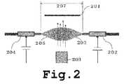
- Fig. 2 shows a conceptual diagram representing a specific example of a state in which droplets are sprayed by the electrospray sprayer and the formed metal particles are blown toward the impregnation object.
- droplets 203 sprayed by an electrospray sprayer 202 comprise the first component
- droplets 205 sprayed by a separate electrospray sprayer 204 comprise the second component.
- the droplets 203 and the droplets 205 are drawn to each other by electrostatic attraction forces, collide, and merge, thereby causing the reaction of the first component and the first component, and the formation of metal particles.
- the metal particles are blown with the gas from a blowing nozzle 208 toward an impregnation object 201 and impregnated therein.
- Specific spraying conditions of the electrospray sprayers are not particularly limited, but it is usually preferred that an electric field be generated between the electrospray sprayer 202 and the separate electrospray sprayer 204.
- the droplets 203 and the droplets 205 are drawn to each other by such an electric field, and the metal particles can be efficiently formed.
- the impregnation method 2 is characterized by comprising a blowing step of blowing the metal particles formed in the reaction step toward an impregnation object, but the blowing method, type of blowing gas, and flow rate of blowing gas in the blowing step, etc. are not particularly limited.
- a method of connecting a pipe to a compressor, a high-pressure cylinder, or the like to supply the blowing gas can be used as the blowing method.
- Air, nitrogen gas, oxygen gas and nitrogen-oxygen mixed gas, etc. can be used as the blowing gas.
- the flow rate of the blowing gas is usually 5 L/min or more, preferably 7 L/min or more, and more preferably 8 L/min or more, and usually 20 L/min or less, preferably 15 L/min or less, and more preferably 12 L/min or less.
- reaction step and blowing step may be separate in time, that is, the blowing step may be performed after the completion of the reaction step, or the reaction step and the blowing step may be performed in parallel at the same time.
- the diameter of the spraying port of the nozzle of the electrospray sprayer in the impregnation methods 1 and 2 is usually 0.03 mm or more, preferably 0.05 mm or more, more preferably 0.1 mm or more, and usually 1.0 mm or less, preferably 0.5 mm or less, more preferably 0.3 mm or less. Where the diameter is within those ranges, the metal particles can be formed with good efficiency.
- the impregnation method 1 is characterized in that the droplets comprising the first component are sprayed toward the impregnation object by the electrospray sprayer, but it is not always necessary that the impregnation object be present on the spraying direction of the electrospray sprayer.
- the impregnation object is preferably present in a range within 45°, more preferably in a range within 30° from the spraying direction of the nozzle of the electrospray sprayer. Within those ranges, the metal particles can be formed with good efficiency.
- the spraying directions of the electrospray sprayer and separate electrospray sprayer in the impregnation methods 1 and 2 are not necessarily present on a straight line.
- the deviation of the spraying directions of the electrospray sprayer and separate electrospray sprayer is preferably present in a range within 45°, more preferably in a range within 30°. Within those ranges, the metal particles can be formed with good efficiency.
- the distance between the electrospray sprayer and the impregnation object in the impregnation method 1 (the shortest distance between the nozzle tip of the electrospray sprayer and the impregnation object; denoted by the reference numeral 106 in Fig. 1 ) is usually 5 mm or more, preferably 7 mm or more, more preferably 10 mm or more, and usually 40 mm or less, preferably 30 mm or less, and more preferably 20 mm or less. Within those ranges, the metal particles can be formed with good efficiency.
- the distance between the electrospray sprayer and the separate electrospray sprayer in the impregnation methods 1 and 2 is usually 10 mm or more, preferably 14 mm or more, more preferably 20 mm or more, and usually 80 mm or less, preferably 60 mm or less, and more preferably 40 mm or less. Within those ranges, the metal particles can be formed with good efficiency.
- the applied voltage in the impregnation methods 1 and 2 is usually 5.5 kV or more, preferably 6 kV or more, more preferably 7 kV or more, and usually 16 kV or less, preferably 15 kV or less, and more preferably 12 kV or less.
- the electric potential applied to the electrospray sprayer when generating an electric field between the impregnation object and the electrospray sprayer is usually a positive potential, and this potential, when ground taken as a reference potential, is usually +2.0 kV or more, preferably +3.0 kV or more, more preferably +4.5 kV or more, and usually +10.0 kV or less, preferably +8 kV or less, even more preferably +7 kV or less.
- the electric potential applied to the impregnation object is usually a negative potential
- this potential in the case of ground taken as a reference potential, is usually -5 kV or more, preferably -4 kV or more, more preferably -3.5 kV or more, and usually -0.5 kV or less, preferably -1 kV or less, even more preferably -2 kV or less.
- the metal particles can be formed with good efficiency.
- the sprayed amount of the droplets in the impregnation methods 1 and 2 is usually 3 ⁇ L/min or more, preferably 5 ⁇ L/min or more, more preferably 7 ⁇ L/min or more, and usually 50 ⁇ L/min or less, preferably 30 ⁇ L/min or less, more preferably 20 ⁇ L/min or less. Within those ranges, the metal particles can be formed with good efficiency.
- the metal particles be formed in a closed space.
- the "closed space” referred to herein means a space surrounded by walls, as the inner space of a box, and it is not necessarily a perfectly closed space.
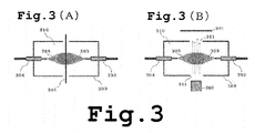
- an inner space 310 of a container 309 in Figs. 3(A) and 3(B) corresponds to the "closed space”.
- 3(A) and 3(B) are disposed in the inner space 310 of the container 309, and the sprayed droplets 303 and droplets 305 are drawn to each other by electrostatic attraction forces, collide, and merge, thereby forming the metal particles inside the space 310.
- two openings 311 are provided in the direction perpendicular to the direction in which the two electrospray sprayers are arranged, an impregnation object 301 is disposed in front of the one opening, and a gas is blown from a blowing nozzle 308 through the other opening 311, thereby enabling more efficient blowing of the gas onto the impregnation object.
- the metal particles are thus formed in the closed space, the metal particles or starting materials for forming the metal particles are prevented from scattering, and the metal particles can be impregnated with better efficiency.
- the types of the metal (element) which is formed and impregnated in the impregnation methods 1 and 2 is not particularly limited, but nobble metals with an ionization tendency less than that of hydrogen are preferred. More specifically, copper, silver, palladium, platinum, and gold are more preferred.
- Physical properties such as the size of the metal particles formed and impregnated in the impregnation methods 1 and 2 are not particularly limited, but metal nanoparticles are particularly useful for impregnation in the impregnation methods 1 and 2.
- the specific average particle size is usually 100 nm or less, preferably 70 nm or less, more preferably 50 nm or less, and usually 1 nm or more, preferably 2 nm or more, and more preferably 3 nm or more.
- the average particle size of the metal particles specifically means a volume-average particle size and can be measured, for example, by electron microscopy or a dynamic light scattering method.
- first component and “second component” means a metal ion and the other means a reducing agent.
- the types of the metal ion needs to be selected, as appropriate, according to the type of the metal particles which are to be impregnated.
- starting materials serving as a metal ion source comprise ligand complexes, metal salts, and hydrates thereof. Specific examples comprise silver nitrate (AgNO 3 ), tetrachloroauric (III) acid (HAuCl 4 ), hexachloroplatinic acid (H 2 PtCl 6 ), and copper (II) chloride (CuCl 2 ).
- the types of the reducing agent are not particularly limited, provided that the agent can reduce the metal ion which is to be used.
- Specific examples comprise inorganic reducing agents such as sodium borohydride, lithium aluminum hydride, sulfites, and nitrites, and organic reducing agents such as hydrazine, ascorbic acid and salts thereof, and oxalic acid and salts thereof.
- a solvent which is to be used for dissolving the first component and/or second component needs to be selected, as appropriate, according to the type of the component, but from the standpoint of cost, water is usually used.
- solvents that can be used in addition to water comprise protic polar solvents such as methanol, ethanol, 1-propyl alcohol, 2-propyl alcohol, butanol, acetic acid, and formic acid; aprotic polar solvents such as acetone, methyl ethyl ketone, acetonitrile, N,N-dimethylformamide, N,N-dimethylacetamide, N-methyl-2-pyrrolidone, and dimethyl sulfoxide; and nonpolar solvents such as hexane, cyclohexane, cyclohexanone, dichloromethane, dichloroethane, trichloroethane, chloroform, trichloroethylene, benzene, ethylbenzene, xy
- the concentration of the first component or second component comprised in the solution which is sprayed by the electrospray sprayer is selected, as appropriate, according to the type of the component, and is usually 0.001% by mass or more, preferably 0.01% by mass or more, more preferably 0.1% by mass or more, and usually 2.0% by mass or less, preferably 1.5% by mass or less, more preferably 1.0 mass% or less. Within those ranges, the metal particles can be formed with good efficiency.
- the types (types of products, materials, etc.) of the impregnation object which is the object of the impregnation method for metal particles of the present invention are not particularly limited, and the method can be applied for impregnating a great variety of products. Since the method is particularly suitable for impregnation with metal particles having an antibacterial activity or a deodorizing activity, such as silver and gold, fiber materials that are strongly required to be subjected to antibacterial/deodorizing treatment are the preferred impregnation objects.
- the impregnation method for metal particles of the present invention can be widely used in a technical field using metal particles, but disclosed herein is the use thereof as an antibacterial/deodorizing method which uses the antibacterial activity of metals and the deodorizing activity thereof based on the suppression of multiplication of bacteria and imparts the antibacterial activity and/or deodorizing activity to the impregnation object.
- the antibacterial/deodorizing method which imparts the antibacterial activity and/or deodorizing activity to the impregnation object on the basis of the impregnation method for metal particles of the present invention is also an aspect of the present invention.
- the impregnation object can be securely impregnated with metal particles. Therefore, the advantage thereof as the antibacterial/deodorizing method is that no binder (binding agent, joining agent) is used for affixing the metal particles.
- a binder suitable for surface processing of fibers since the exposed surface area of metallic silver particles is reduced, the effect thereof is weakened.
- the impregnation method for metal particles of the present invention enables the "binder-free" usage, it is possible to manufacture a fiber material with excellent antibacterial ability. Therefore, the antibacterial/deodorizing method which is an aspect of the present invention is advantageous as a method using no binder.
- the impregnation method for metal particles of the present invention can be used, for example, as an antibacterial/deodorizing method for imparting the antibacterial activity and/or deodorizing activity to the impregnation object, but a method for manufacturing fiber material which comprises such antibacterial/deodorizing method as an antibacterial/deodorizing treatment step is also an aspect of the present invention (can be referred to hereinbelow in abbreviated form as "manufacturing method according to the present invention").
- the manufacturing method of the present invention may comprise well-known steps that are performed in the processes for manufacturing fiber materials, for example, a fiber forming step (melt fiber forming, dry fiber forming, wet fiber forming), a stretching step, a spinning step, a knitting and weaving step, and a scouring step.
- a fiber forming step (melt fiber forming, dry fiber forming, wet fiber forming)
- a stretching step for example, a spinning step
- a spinning step a spinning step
- a knitting and weaving step a scouring step.
- the impregnation method for metal particles of the present invention is suitable for continuously performing the antibacterial/deodorizing treatment of a fiber material and makes it possible to increase greatly the productivity of fiber materials when implemented continuously in combination with a fiber forming step or the like.
- the manufacturing method of the present invention preferably further comprises at least one step selected from a group consisting of a fiber forming step, a stretching step, a spinning step, a knitting and weaving step, and a scouring step.
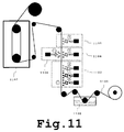
- the continuous treatment such as depicted in Fig. 11 is a specific mode of using the manufacturing method of the present invention (can be referred to hereinbelow in abbreviated form as "the mode illustrated by Fig. 11 ")
- the reference numeral 1101 stands for a fiber material before processing (for example, a cotton yarn)
- 1102 - a water tank that contains an electrolyte solution 1103 - a dyeing treatment step
- 1105 - a sizing treatment step 1106 - an electrospray sprayer, and 1107 - a heating and drying device.
- the mode illustrated by Fig. 11 is a line production method in which a cotton yarn (fiber material) is moved using a roller.
- the cotton yarn passes successively through the water tank that contains the electrolyte solution, dyeing treatment step, functional material addition (antibacterial/deodorizing treatment) step, sizing treatment step, and heating and drying device.
- the impregnation method for metal particles of the present invention in particular the impregnation method comprising a reaction step of spraying liquid droplets comprising a first component onto an impregnation object with an electrospray sprayer and forming metal particles by a reaction with a second component that is comprised in the impregnation object and/or comprised in droplets sprayed by a separate electrospray sprayer, enables the impregnation of metal particles with good efficiency, and a metal particle impregnation device which can use such impregnation method is also an aspect of the present invention (can be referred to hereinbelow in abbreviated form as "metal particle impregnation device 1").
- the metal particle impregnation device 1 is characterized in comprising a second component solution contact mechanism that performs at least one selected from a group consisting of immersing an impregnation object in a second component solution, spraying the second component solution onto the impregnation object, and dropping the second component solution onto the impregnation object; an electrospray sprayer that sprays droplets comprising a first component onto the impregnation object comprising the second component; and an impregnation object feed mechanism for moving the impregnation object comprising the second component to a spray target for the electrospray sprayer.
- a second component solution contact mechanism that performs at least one selected from a group consisting of immersing an impregnation object in a second component solution, spraying the second component solution onto the impregnation object, and dropping the second component solution onto the impregnation object
- an electrospray sprayer that sprays droplets comprising a first component onto the impregnation object comprising the
- the impregnation method comprising: a reaction step of spraying liquid droplets comprising a first component with an electrospray sprayer and forming metal particles by a reaction with a second component that is comprised in droplets sprayed by a separate electrospray sprayer; and a blowing step of blowing the metal particles formed in the reaction step toward an impregnation object also enables the impregnation of metal particles with good efficiency, and a metal particle impregnation device which can use such impregnation method is also an aspect of the present invention (can be referred to hereinbelow in abbreviated form as "metal particle impregnation device 2").
- the metal particle impregnation device 2 is characterized in comprising: an electrospray sprayer that sprays droplets comprising a first component; an electrospray sprayer that sprays droplets comprising a second component; and a blowing mechanism that blows metal particles formed by a reaction of the sprayed first and second components toward an impregnation object.
- a device to be used in the second component contact mechanism in the metal particle impregnation device 1 is not particularly limited, provided that an arrangement is obtained for performing at least one selected from a group consisting of immersing the impregnation object into a second component solution, spraying the second component solution onto the impregnation object, and dropping the second component solution onto the impregnation object.
- an arrangement in which an impregnation object 401 is immersed in an immersion liquid tank 413 into which a second component solution 414 has been loaded as depicted in Fig. 4(A)
- an arrangement in which the second component solution 414 is sprayed onto the impregnation object 401 by using a spraying device 415 as depicted in Fig. 4(B)
- an arrangement in which the second component solution 414 is dropped onto the impregnation object 401 by using a dropping device 416 as depicted in Fig. 4(C)
- a device to be used in the impregnation object feed mechanism in the metal particle impregnation device 1 is not particularly limited, provided that an arrangement is obtained such that the impregnation object comprising the second component can be moved to the spray target for the electrospray sprayer.
- a roller conveyor or a belt conveyor can be used.
- a device to be used in the blowing mechanism in the metal particle impregnation device 2 is not particularly limited, provided that an arrangement is obtained such that the metal particles formed by the reaction of the sprayed first component and second component can be blown toward the impregnation object.
- a device can be used in which a gas source, such as a compressor and a high-pressure cylinder, a pipe, and a nozzle are combined.
- metal particle impregnation device 1 is not particularly limited, but it is preferred that the device be configured such that the distance between the electrospray sprayer and the impregnation object, or the spraying direction of the electrospray sprayer could be changed. By enabling such changes, it is possible to adapt the device to various conditions.
- metal particle impregnation device 2 is not particularly limited, but it is preferred that the device be configured such that the distance between the electrospray sprayers, or the spraying direction of the electrospray sprayers could be changed. By enabling such changes, it is possible to adapt the device to various conditions.
- a power source (voltage-controlled device) that generates an electric field in the electrospray sprayer have a variable application voltage. Where the application voltage can be changed, it is possible to adapt the device to various conditions.
- FIG. 5 An attached white cloth (material: cotton; size for JIS L 0803 color fastness test is 10 cm ⁇ 10 cm) and two electrospray sprayers were arranged as shown in the conceptual diagram depicted in Fig. 5 (in Fig. 5 , the reference numeral 501 stands for a cotton cloth, 502 - a nozzle of an electrospray sprayer, 503 - sprayed silver nitrate solution, 504 - a nozzle of an electrospray sprayer, 505 - sprayed ascorbic acid solution, 508 - a blowing nozzle, and 509 - an acrylic hood).
- the reference numeral 501 stands for a cotton cloth, 502 - a nozzle of an electrospray sprayer, 503 - sprayed silver nitrate solution, 504 - a nozzle of an electrospray sprayer, 505 - sprayed ascorbic acid solution, 508 - a blowing nozzle, and 509 - an acrylic
- Glass capillaries (opening diameter: 0.1 mm) with an electrode attached to the tip thereof were used as nozzles in the two electrospray sprayers, and the nozzle tips were arranged in the acrylic hood surrounding the respective spraying regions and fixed such as to face each other (the distance between the nozzles of the two electrospray sprayers: 40 mm).
- the acrylic hood was provided with two openings in the direction perpendicular to the arrangement direction of the two electrospray sprayers, an attached white cloth was disposed in front of the one opening, and a gas was blown from the other opening, thereby blowing the gas onto the attached white cloth.
- a potential of +7.0 kV was applied to the electrode of the nozzle of the electrospray sprayer filled with the silver nitrate solution
- a potential of -2.8 kV (reference potential: ground) was applied to the electrode of the nozzle of the electrospray sprayer filled with the ascorbic acid solution
- nitrogen gas was blown at a rate of 2.0 L/min from the opening in the acrylic hood, and the spraying of the silver nitrate solution and ascorbic acid solution and the blowing of the nitrogen gas onto the attached white cloth were performed simultaneously for 3 min.
- the attached white cloth was recovered, dried and then qualitatively analyzed by characteristic X-ray analysis and texture observations under a scanning electron microscope. The results have confirmed that metallic silver particle have been formed on the surface of the cotton yarn constituting the attached white cloth (see Figs. 6 and 7 ).
- an attached white cloth can be impregnated with metallic silver particles by forming the metallic silver particles by spraying droplets comprising silver nitrate and droplets comprising ascorbic acid from respective electrospray sprayers and then blowing the metallic silver particles toward the attached white cloth which is the impregnation object.
- droplets bearing a positive charge are sprayed from the nozzle 502 of one electrospray sprayer and droplets bearing a negative charge are sprayed from the nozzle 504 of the other electrospray sprayer.
- An electric field is formed between the nozzle 502 and the nozzle 504, and the charged droplets are moved along the electric field such that the positively charged droplets move from a high-potential side to a low-potential side, whereas the negatively charged droplets move from a low-potential side to a high-potential side.
- the positively charged droplets and negatively charged droplets collide and chemical components thereof react with each other. After the collision, the droplets become electrically neutral.
- the positively and negatively charged droplets move, while colliding, to the impregnation object 501 and are uniformly applied thereto.
- Another advantage of such blowing is that it increases the collision probability of the positively charged droplets and negatively charged droplets, thereby increasing the reaction efficiency.
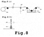
- the reference numeral 801 stands for a cotton yarn, 802 - a nozzle of an electrospray sprayer, 803 - a sprayed silver nitrate solution, 804 - an ascorbic acid solution, 805 - an immersion liquid tank, 806 - a roller, 807 - electrodes for voltage application, and 808 - a winding roll).
- a stainless steel nozzle with an opening diameter of the spraying port of 0.1 mm was used for the electrospray sprayer.
- the cotton yarn was then positioned on the spraying direction (horizontal direction) of the nozzle, and the nozzle tip and cotton yarn were fixed such that the shortest distance therebetween was 20 mm.
- the cotton yarn was immersed for about 2 sec into the ascorbic acid solution, and the cotton yarn was then wound such as to move to the spray target for the electrospray sprayer at a rate of 1 m/min (the content of the ascorbic acid solution on the cotton yarn: 400% by mass).
- the silver nitrate solution was sprayed from the electrospray sprayer toward the cotton yarn which has passed through the ascorbic acid solution.
- the spraying was performed by applying +6.0 kV to the nozzle electrode and -3.0 kV to the cotton yarn (reference potential: ground).
- Cotton yarns impregnated with metallic silver particles were prepared by the same method as in Example 2, except that the feed rate (winding rate) of the cotton yarn was changed, and the impregnated amount of the metallic silver particles was measured before and after washing with water.
- the impregnated amount of the metallic silver particles was determined by eluting silver with nitric acid and measuring the amount of silver ions in the solution with an atomic absorption spectrometer in the same manner as in Example 2.
- Fig. 12 shows the graph representing the relationship between the feed rate of the cotton yarn and the impregnated amount of the metallic silver particles.
- the impregnated amount of the metallic silver particles tends to decrease with the increase in the feed rate of the cotton yarn, but since the difference between the impregnated amount of the metallic silver particles before and after washing with water decreases, it can be supposed that the impregnation with excess metallic silver particles which can easily fall from the yarn is suppressed and that securely impregnated metallic silver particles are selectively formed. Further, it is clear that by using the impregnation method for metal particles of the present invention it is possible to impregnate the impregnation object securely with the metallic silver particles, without using a binder (binding agent, joining agent).
- the antibacterial ability of the cotton yarn impregnated with metallic silver particles of Example 2 was evaluated.
- the antibacterial ability was evaluated by a method conforming to JIS L1902 (Antibacterial ability test method for fiber products and antibacterial effect).
- Staphylococcus aureus IFO12732 was used as bacteria.
- the cotton yarn 0.15 g, was placed in a vial, and a test bacterial solution, 0.2 ml, was inoculated and cultured for 18 h at 35°C.
- the bacteriostatic activity value is the logarithmic representation of a value obtained by dividing the number of viable bacteria in the standard yarn after culturing for 18 h by the number of viable bacteria in the processed yarn after culturing for 18 h. Where the bacteriostatic activity value is 2.0 or more, it is assumed that the antibacterial/deodorizing effect is demonstrated.
- the bactericidal activity value is the logarithmic representation of a value obtained by dividing the number of viable bacteria in the standard yarn immediately after the inoculation by the number of viable bacteria in the processed yarn after culturing for 18 h. Where the bactericidal activity value is 0 or more, it is assumed that the antibacterial effect is demonstrated.
- the impregnation method for metal particles of the present invention enables efficient impregnation, for example, with silver particles or gold particles exhibiting an antibacterial activity and/or a deodorizing activity. Therefore, the method can be used for antibacterial/deodorizing treatment.
Landscapes
- Engineering & Computer Science (AREA)
- Textile Engineering (AREA)
- Chemical & Material Sciences (AREA)
- Inorganic Chemistry (AREA)
- Chemical Kinetics & Catalysis (AREA)
- General Chemical & Material Sciences (AREA)
- Chemical Or Physical Treatment Of Fibers (AREA)
- Manufacture Of Metal Powder And Suspensions Thereof (AREA)
- Disinfection, Sterilisation Or Deodorisation Of Air (AREA)
- Chemically Coating (AREA)
- Other Surface Treatments For Metallic Materials (AREA)
- Electrostatic Spraying Apparatus (AREA)
Abstract
Description
- The present invention relates to an impregnation method for metal particles, an antibacterial/deodorizing method, a method for manufacturing a fiber material, and a metal particle impregnation device, and more particularly to a method capable of impregnating an object with metal particles, such as silver or gold particles, uniformly and in a simple manner in a process for manufacturing an industrial product.
- Awareness of health and hygiene of the people has been steadily growing in recent years, and products to which an antibacterial activity and a deodorizing activity have been imparted are actively sold in the fields of food, clothing, and domestic products. In particular, fiber materials which are used in the field of clothing, bedding, and interior materials often come into direct contact with the body, and a variety of antibacterial/deodorizing techniques relating to such materials have been developed.
- Metal ions such as silver and copper ions have been known for a long time as typical components having an antibacterial activity, and antibacterial agents utilizing these metal ions have been put to practical use. For example, an example of using a special phosphate-based compound having a silver ion as an antibacterial agent has been reported (see PTL 1). Further, fibers obtained by mixing a layered compound containing metal ions, such as silver and copper ions, with a thermoplastic polymer have also been reported as a fiber material having an antibacterial activity, and such fiber material has been disclosed to be excellent in washing durability (see PTL 2).
- Meanwhile, a phenomenon called "electrospray" in which a liquid is sprayed in the form of charged droplets toward a counter electrode as a result of applying a high voltage between a nozzle filled with the liquid and the counter electrode has been used for mass analysis (see PTL 3) and deposition of polymer compounds (see PTL 4). Since the electrospray phenomenon enables ionization without requiring such conditions as high temperature, it is advantageous for mass analysis of easily destructible compounds such as biopolymers. It is also well known that because very small droplets of easily vaporizable solvents can be sprayed, the electrospray phenomenon is advantageous for forming nanoparticles or carbon nanofibers.
-
- PTL 1:
Japanese Patent Application Publication No. H03-083905 - PTL 2:
Japanese Patent Application Publication No. H05-051812 - PTL 3:
Japanese Patent Application Publication No. H06-215729 - PTL 4:
Japanese Patent Application Publication No. 2007-070738 - Problems associated with a method for imparting an antibacterial activity by coating an antibacterial agent including metal ions such as silver or copper ions, or kneading the agent with fibers are that the method is not versatile and that uniform impregnation of the metal component cannot be performed in a simple manner. Problems associated with a method in which fibers are immersed in an antibacterial agent solution are that portions which do not require the antibacterial processing are still subjected to such processing and that the wastewater treatment of the antibacterial agent solution is costly.
- For example, a technique enabling uniform and simple impregnation of an object with metal particles of silver or copper in the process of manufacturing an industrial product, and a technique by which only the necessary portion of the product can be impregnated with the metal particles would be important in reducing the production cost of products having an antibacterial activity or a deodorizing activity.
- Thus, it is an objective of the present invention to provide a method by which impregnation with metal particles can be performed uniformly and in a simple manner.
- The inventors have conducted a comprehensive study aimed at the resolution of the above-described problems. The results obtained have demonstrated that an object can be impregnated with metal particles uniformly and in a simple manner by forming the metal particles by spraying droplets comprising a metal ion or a reducing agent with an electrospray sprayer. This finding led to the creation of the present invention.
- Thus, the present invention relates to:
- <1> An impregnation method for metal particles, comprising a reaction step of spraying liquid droplets comprising a first component onto an impregnation object with an electrospray sprayer and forming metal particles by a reaction with a second component that is comprised in the impregnation object and/or comprised in droplets sprayed by a separate electrospray sprayer.
- <2> An impregnation method for metal particles, comprising a reaction step of spraying liquid droplets comprising a first component with an electrospray sprayer and forming metal particles by a reaction with a second component that is comprised in droplets sprayed by a separate electrospray sprayer; and a blowing step of blowing the metal particles formed in the reaction step toward an impregnation object.
- <3> The impregnation method for metal particles according to <1> or <2>, wherein the reaction step is a step of forming metal particles in a closed space.
- <4> The impregnation method for metal particles according to any one of <1> to <3>, wherein the impregnation object is a fiber material.
- <5> The impregnation method for metal particles according to any one of <1> to <4>, wherein the metal particles are of at least one type selected from a group consisting of copper particles, silver particles, palladium particles, platinum particles, and gold particles.
- <6> The impregnation method for metal particles according to any one of <1> to <5>, wherein the metal particles have an average particle size of 1 nm to 100 nm.
- <7> An antibacterial/deodorizing method that imparts an antibacterial activity and/or a deodorizing activity to the impregnation object by the impregnation method for metal particles according to any one of <1 > to <6>.
- <8> A method for manufacturing a fiber material comprising an antibacterial/deodorizing treatment step of imparting an antibacterial activity and/or a deodorizing activity to the fiber material by the antibacterial/deodorizing method according to <7>.
- <9> The method for manufacturing a fiber material according to <8>, further comprising at least one step selected from a group consisting of a fiber forming step, a stretching step, a spinning step, a knitting and weaving step, a bleaching step, a sizing step, a scouring step, and a dyeing step.
- <10> A metal particle impregnation device comprising: a second component solution contact mechanism that performs at least one selected from a group consisting of immersing an impregnation object in a second component solution, spraying the second component solution onto the impregnation object, and dropping the second component solution onto the impregnation object; an electrospray sprayer that sprays droplets comprising a first component onto the impregnation object comprising the second component; and an impregnation object feed mechanism for moving the impregnation object comprising the second component to a spray target for the electrospray sprayer.
- <11> A metal particle impregnation device comprising: an electrospray sprayer that sprays droplets comprising a first component; an electrospray sprayer that sprays droplets comprising a second component; and a blowing mechanism that blows metal particles formed by a reaction of the sprayed first and second components toward an impregnation object.
- According to the present invention, an object can be impregnated with metal particles uniformly and in a simple manner, and the production cost of a product imparted with an antibacterial activity or a deodorizing activity can be reduced.
-
- [
Fig. 1 ]
Fig. 1(A) is a conceptual diagram representing a reaction step of spraying liquid droplets comprising a first component onto an impregnation object with an electrospray sprayer and forming metal particles by a reaction with a second component that is comprised in the impregnation object;Fig. 1(B) is a conceptual diagram representing a reaction step of spraying liquid droplets comprising a first component with an electrospray sprayer and disposing an impregnation object in a reaction field in which metal particles are formed by a reaction with a second component that is comprised in droplets sprayed by a separate electrospray sprayer, thereby impregnating the impregnation object with the metal particles;Fig. 1 (C) is a photograph (photograph replacing the drawing) showing how the droplets sprayed from an electrospray sprayer are focused toward a cotton yarn; andFig. 1(D) is a conceptural diagram representing the mode in which the droplets sprayed from an electrospray sprayer are focused toward a cotton yarn. - [
Fig. 2 ]
Fig. 2 is a conceptual diagram representing a reaction step of spraying liquid droplets comprising a first component with an electrospray sprayer and forming metal particles by a reaction with a second component that is comprised in droplets sprayed by a separate electrospray sprayer, and a blowing step of blowing the formed metal particles toward an impregnation object. - [
Fig. 3 ]
Fig. 3(A) is a conceptual diagram representing a reaction step of forming metal particles in a closed space and impregnating the impregnation object therewith; andFig. 3(B) is a conceptual diagram representing a reaction step of forming metal particles in a closed space and a blowing step of blowing the formed metal particles from the opening of the closed space toward the impregnation object. - [
Fig. 4 ]
Fig. 4(A) is a conceptual diagram representing a mode in which the reaction step is performed continuously after the impregnation object has been immersed in the second component solution as a reaction preparation step;Fig. 4(B) is a conceptual diagram representing a mode in which the reaction step is performed continuously after the second component solution has been sprayed onto the impregnation object as a reaction preparation step; andFig. 4(C) is a conceptual diagram representing a mode in which the reaction step is performed continuously after the second component solution has been dropped onto the impregnation object as a reaction preparation step. - [
Fig. 5 ]
Fig. 5 is a conceptual diagram of the device used in Example 1. - [
Fig. 6 ]
Figs. 6 are scanning electron micrographs of a cotton cloth impregnated with metallic silver particles in Example 1:Fig. 6(A) is a photo obtained under a magnification of 1000; andFig. 6(B) is a photo obtained under a magnification of 3000 (photos replacing the drawings). - [
Fig. 7 ]
Figs. 7 are mapping images of Ag obtained by EDAX of a cotton cloth impregnated with metallic silver particles in Example 1:Fig. 7(A) is an original image; andFig. 7(B) is an Ag mapping image (photos replacing the drawings). - [
Fig. 8 ]
Fig. 8(A) is a conceptual diagram of the device used in Example 2; andFig. 8(B) is a bird's-eye view of the electrospray sprayer portion of the device used in Example 2. - [
Fig. 9 ]
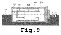
Fig. 9 is a conceptual diagram of a device for washing a cotton yarn with water. - [
Fig. 10 ]
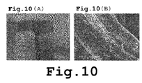
Fig. 10(A) are photos (photos replacing the drawings) showing a cotton yarn before impregnation with metallic silver particles (left side) and the cotton yarn impregnated with metallic silver particles in Example 2 (right side); andFig. 10(B) is a scanning electron micrograph (photo replacing the drawing) of the cotton yarn impregnated with metallic silver particles in Example 2. - [
Fig. 11 ]
Fig. 11 is a conceptual diagram illustrating how a cotton yarn successively passes through a tank filled with an electrolyte solution, a dyeing treatment step, a functional material addition (antibacterial/deodorizing treatment) step, a sizing treatment step and a heating and drying device. - [
Fig. 12 ]
Fig. 12 is a graph representing the relationship between the feed rate of a cotton yarn and the impregnated amount of metallic silver particles. - The impregnation method for metal particles, antibacterial/deodorizing method, method for manufacturing a fiber material, and metal particle impregnation device, which are the embodiments of the present invention, are explained hereinbelow in detail by referring to specific examples, but they are not limited to the contents described hereinbelow and can be changed, as appropriate, provided that they do not depart from the essence according to the present invention.
- The impregnation method for metal particles which is an aspect of the present invention is characterized in comprising a reaction step of spraying liquid droplets comprising a first component onto an impregnation object with an electrospray sprayer and forming metal particles by a reaction with a second component that is comprised in the impregnation object and/or comprised in droplets sprayed by a separate electrospray sprayer (this aspect can be referred to hereinbelow in abbreviated form as "impregnation method 1 ").
- One more impregnation method for metal particles which is an aspect of the present invention is characterized in comprising a reaction step of spraying liquid droplets comprising a first component with an electrospray sprayer and forming metal particles by a reaction with a second component that is comprised in droplets sprayed by a separate electrospray sprayer; and a blowing step of blowing the metal particles formed in the reaction step toward an impregnation object (this aspect can be referred to hereinbelow in abbreviated form as "impregnation method 2").
- The inventors have conducted a comprehensive research of impregnation methods for metal particles, such as silver and gold particles, that can be used in the process for manufacturing an industrial product. The results obtained have demonstrated that an object can be impregnated with metal particles uniformly and in a simple manner by forming the metal particles by spraying droplets comprising a metal ion or a reducing agent with an electrospray sprayer. The "electrospray sprayer" is a spraying device that uses a phenomenon in which a liquid is sprayed in the form of charged droplets toward a counter electrode as a result of applying a high voltage between a nozzle filled with the liquid and the counter electrode, and because very small charged droplets are sprayed, a state with dispersed metal particles or a starting material thereof can be produced. As a result, the object can be uniformly impregnated with the metal particles. Further, since the metal particles are formed by spraying, the method is simpler than the methods using immersion and coating.
- In the present invention, the specific structure of the "electrospray sprayer" is not particularly limited, provided that it is a spraying device using the electrospray phenomenon, but the electrospray sprayer is usually equipped at least with a nozzle for defining the spraying direction, and a power source (voltage-controlled device; comprises an electrode, a conductive wire, etc., connecting the nozzle and impregnation object (or the nozzle of a separate electrospray sprayer)) for generating an electric field (when two or more electrospray sprayers are used, the electrospray sprayers may share a power source, or each of the electrospray sprayers may not be equipped with an individual power source). The nozzle itself is fabricated from an electrically conductive material, or an electrode (for example, a platinum wire) is disposed in the nozzle, and the arrangement is such that an electric field is generated by connection to the power source (voltage-controlled device, etc.) and application of a voltage.
- As for the "first component" and "second component", one of them means a metal ion and the other means a reducing agent. Thus, when the "first component" is a metal ion, the "second component" means a reducing agent, and when the "first component" is a reducing agent, the "second component" means a metal ion.
- The impregnation method 1 is characterized by comprising a reaction step of spraying liquid droplets comprising a first component onto an impregnation object with an electrospray sprayer and forming metal particles by a reaction with a second component that is comprised in the impregnation object and/or comprised in droplets sprayed by a separate electrospray sprayer.
Figs. 1(A) and 1(B) show conceptual diagrams representing specific examples of a state in which droplets are sprayed onto an impregnation object with an electrospray sprayer. - For example, in the configuration depicted in
Fig. 1(A) , animpregnation object 101 comprises the second component, anddroplets 103 sprayed by anelectrospray sprayer 102 comprise the first component. In this arrangement, the sprayeddroplets 103 reach theimpregnation object 101, the first component and second component react with each other on the surface of theimpregnation object 101, metal particles are formed, and the impregnation object is impregnated therewith (theimpregnation object 101 and theelectrospray sprayer 102 are connected through electrodes, conductive wire, and power source, etc.). Specific spraying conditions of the electrospray sprayer are not particularly limited, but it is usually preferred that an electric field be generated between theimpregnation object 101 and theelectrospray sprayer 102. The electric field between the impregnation object and electrospray sprayer can be generated by using, for example, an electric power source and setting the electrospray sprayer side to a positive potential and setting the impregnation object side to 0 kV or a negative potential, or by setting the electrospray sprayer side to a negative potential and setting the impregnation object side to 0 kV or a positive potential. Further, since a potential gradient may be created between the impregnation object and the electrospray sprayer, the electric field can be generated, for example, also when (potential of electrospray sprayer) > (potential of impregnation object) > 0, or when 0 V > (potential of impregnation object) > (potential of electrospray sprayer). Since the generated chargeddroplets 103 are drawn (focused) by such electric field to theimpregnation object 101, as depicted inFigs. 1(C) and 1(D) , the metal particles can be formed with good efficiency. - Meanwhile, in the configuration depicted in
Fig. 1(B) , thedroplets 103 sprayed by theelectrospray sprayer 102 comprise the first component, anddroplets 105 sprayed by aseparate electrospray sprayer 104 comprise the second component. In such an arrangement, thedroplets 103 and thedroplets 105 are drawn to each other by electrostatic attraction forces, collide, and merge, thereby causing the reaction of the first component and second component in the vicinity of theimpregnation object 101 and the formation and impregnation of metal particles (theelectrospray sprayer 102 and theseparate electrospray sprayer 104 are connected through electrodes, conductive wire, and power source). Specific spraying conditions of the electrospray sprayers are not particularly limited, but it is usually preferred that an electric field be generated between theelectrospray sprayer 102 and theseparate electrospray sprayer 104. The electric field between theelectrospray sprayer 102 and theseparate electrospray sprayer 104 can be generated by using, for example, an electric power source and setting theelectrospray sprayer 102 side to a positive potential and setting theelectrospray sprayer 104 side to 0 kV or a negative potential, or by setting theelectrospray sprayer 102 side to a negative potential and setting theelectrospray sprayer 104 side to 0 kV or a positive potential. Further, as long as there is a potential gradient between theelectrospray sprayer 102 and theseparate electrospray sprayer 104, the electric field can be generated, for example, also when (potential of the electrospray sprayer 101) > (potential of the separate electrospray sprayer 104) > 0, or when 0 V > (potential of the separate electrospray sprayer 104) > (potential of the electrospray sprayer 101). Thedroplets 103 and thedroplets 105 are drawn to each other by such an electric field, and the metal particles can be efficiently formed. - The impregnation method 1 may comprise steps other than the above-mentioned reaction step. For example, a reaction preparation step can be comprised in which the second component is comprised in the impregnation object to induce the reaction with the first component contained in the droplets.
- A method for comprising the second component into the impregnation object in the reaction preparation step is not particularly limited, and suitable examples thereof comprise a method of immersing the impregnation object into a solution in which the second component is dissolved in a solvent (can be referred to hereinbelow in abbreviated form as "second component solution"), a method of spraying a second component solution onto the impregnation object, and a method of dropping the second component solution onto the impregnation object.
- The solvent to be used for dissolving the second component needs to be selected, as appropriate, according to the type of the second component. From the standpoint of cost, water is usually used. Examples of solvents that can be used in addition to water comprise protic polar solvents such as methanol, ethanol, 1-propyl alcohol, 2-propyl alcohol, butanol, acetic acid, and formic acid; aprotic polar solvents such as acetone, methyl ethyl ketone, acetonitrile, N,N-dimethylformamide, N,N-dimethylacetamide, N-methyl-2-pyrrolidone, and dimethyl sulfoxide; and nonpolar solvents such as hexane, cyclohexane, cyclohexanone, dichloromethane, dichloroethane, trichloroethane, chloroform, trichloroethylene, benzene, ethylbenzene, xylene, toluene, diethyl ether, 1,4-dioxane, methyl acetate, ethyl acetate, tetrahydrofuran, and methylene chloride. Those solvents may be used not only individually, but also in combinations of two or more thereof.
- The concentration of the second component solution is usually 0.001% by mass or more, preferably 0.01% by mass or more, more preferably 0.1 % by mass or more, and usually 20.0% by mass or less, preferably 15.0% by mass or less, more preferably 10.0 mass% or less.
- The content of the second component solution comprised in the impregnation object (mass of the second component solution in 100% by mass of the impregnation object) is usually 300% by mass or more, preferably 400% by mass or more, more preferably 500% by mass or more, and usually 1000% by mass or less, preferably 850% by mass or less, more preferably 700% by mass or less.
- When the impregnation object is an insulator such as a fiber material, the electric field is difficult to generate between the impregnation object and the electrospray sprayer. The inventors have discovered that by comprising the second component solution, it is possible to generate an electric field between the impregnation object and the electrospray sprayer and to form metal particles with good efficiency even when the impregnation object is an insulator such as a fiber material. This is because the second component typically acts as an electrolyte.
- The impregnation method 2 is characterized by comprising a reaction step of spraying liquid droplets comprising a first component with an electrospray sprayer and forming metal particles by a reaction with a second component that is comprised in droplets sprayed by a separate electrospray sprayer; and a blowing step of blowing the metal particles formed in the reaction step toward an impregnation object.
Fig. 2 shows a conceptual diagram representing a specific example of a state in which droplets are sprayed by the electrospray sprayer and the formed metal particles are blown toward the impregnation object. - For example, in the configuration depicted in
Fig. 2 ,droplets 203 sprayed by anelectrospray sprayer 202 comprise the first component, anddroplets 205 sprayed by aseparate electrospray sprayer 204 comprise the second component. In such an arrangement, thedroplets 203 and thedroplets 205 are drawn to each other by electrostatic attraction forces, collide, and merge, thereby causing the reaction of the first component and the first component, and the formation of metal particles. The metal particles are blown with the gas from a blowingnozzle 208 toward animpregnation object 201 and impregnated therein. Specific spraying conditions of the electrospray sprayers are not particularly limited, but it is usually preferred that an electric field be generated between theelectrospray sprayer 202 and theseparate electrospray sprayer 204. Thedroplets 203 and thedroplets 205 are drawn to each other by such an electric field, and the metal particles can be efficiently formed. - The impregnation method 2 is characterized by comprising a blowing step of blowing the metal particles formed in the reaction step toward an impregnation object, but the blowing method, type of blowing gas, and flow rate of blowing gas in the blowing step, etc. are not particularly limited. A method of connecting a pipe to a compressor, a high-pressure cylinder, or the like to supply the blowing gas can be used as the blowing method. Air, nitrogen gas, oxygen gas and nitrogen-oxygen mixed gas, etc. can be used as the blowing gas.
- The flow rate of the blowing gas is usually 5 L/min or more, preferably 7 L/min or more, and more preferably 8 L/min or more, and usually 20 L/min or less, preferably 15 L/min or less, and more preferably 12 L/min or less.
- Further, the reaction step and blowing step may be separate in time, that is, the blowing step may be performed after the completion of the reaction step, or the reaction step and the blowing step may be performed in parallel at the same time.
- The diameter of the spraying port of the nozzle of the electrospray sprayer in the impregnation methods 1 and 2 is usually 0.03 mm or more, preferably 0.05 mm or more, more preferably 0.1 mm or more, and usually 1.0 mm or less, preferably 0.5 mm or less, more preferably 0.3 mm or less. Where the diameter is within those ranges, the metal particles can be formed with good efficiency.
- The impregnation method 1 is characterized in that the droplets comprising the first component are sprayed toward the impregnation object by the electrospray sprayer, but it is not always necessary that the impregnation object be present on the spraying direction of the electrospray sprayer. Thus, the impregnation object is preferably present in a range within 45°, more preferably in a range within 30° from the spraying direction of the nozzle of the electrospray sprayer. Within those ranges, the metal particles can be formed with good efficiency.
- The spraying directions of the electrospray sprayer and separate electrospray sprayer in the impregnation methods 1 and 2 are not necessarily present on a straight line. However, the deviation of the spraying directions of the electrospray sprayer and separate electrospray sprayer is preferably present in a range within 45°, more preferably in a range within 30°. Within those ranges, the metal particles can be formed with good efficiency.
- The distance between the electrospray sprayer and the impregnation object in the impregnation method 1 (the shortest distance between the nozzle tip of the electrospray sprayer and the impregnation object; denoted by the
reference numeral 106 inFig. 1 ) is usually 5 mm or more, preferably 7 mm or more, more preferably 10 mm or more, and usually 40 mm or less, preferably 30 mm or less, and more preferably 20 mm or less. Within those ranges, the metal particles can be formed with good efficiency. - The distance between the electrospray sprayer and the separate electrospray sprayer in the impregnation methods 1 and 2 (the shortest distance between the nozzle tips of the electrospray sprayer and the separate electrospray sprayer; denoted by the
reference numeral 107 inFig. 1 ) is usually 10 mm or more, preferably 14 mm or more, more preferably 20 mm or more, and usually 80 mm or less, preferably 60 mm or less, and more preferably 40 mm or less. Within those ranges, the metal particles can be formed with good efficiency. - The applied voltage in the impregnation methods 1 and 2 is usually 5.5 kV or more, preferably 6 kV or more, more preferably 7 kV or more, and usually 16 kV or less, preferably 15 kV or less, and more preferably 12 kV or less.
- Further, the electric potential applied to the electrospray sprayer when generating an electric field between the impregnation object and the electrospray sprayer is usually a positive potential, and this potential, when ground taken as a reference potential, is usually +2.0 kV or more, preferably +3.0 kV or more, more preferably +4.5 kV or more, and usually +10.0 kV or less, preferably +8 kV or less, even more preferably +7 kV or less. Meanwhile, the electric potential applied to the impregnation object is usually a negative potential, and this potential, in the case of ground taken as a reference potential, is usually -5 kV or more, preferably -4 kV or more, more preferably -3.5 kV or more, and usually -0.5 kV or less, preferably -1 kV or less, even more preferably -2 kV or less.
- Within those ranges, the metal particles can be formed with good efficiency.
- The sprayed amount of the droplets in the impregnation methods 1 and 2 is usually 3 µL/min or more, preferably 5 µL/min or more, more preferably 7 µL/min or more, and usually 50 µL/min or less, preferably 30 µL/min or less, more preferably 20 µL/min or less. Within those ranges, the metal particles can be formed with good efficiency.
- Other conditions of the reaction step in the impregnation methods 1 and 2 are not particularly limited, but it is preferred that the metal particles be formed in a closed space. The "closed space" referred to herein means a space surrounded by walls, as the inner space of a box, and it is not necessarily a perfectly closed space. For example, an
inner space 310 of acontainer 309 inFigs. 3(A) and 3(B) corresponds to the "closed space". The nozzle tips of anelectrospray sprayer 302 and aseparate electrospray sprayer 304 inFigs. 3(A) and 3(B) are disposed in theinner space 310 of thecontainer 309, and the sprayeddroplets 303 anddroplets 305 are drawn to each other by electrostatic attraction forces, collide, and merge, thereby forming the metal particles inside thespace 310. InFig. 3(B) , twoopenings 311 are provided in the direction perpendicular to the direction in which the two electrospray sprayers are arranged, animpregnation object 301 is disposed in front of the one opening, and a gas is blown from a blowingnozzle 308 through theother opening 311, thereby enabling more efficient blowing of the gas onto the impregnation object. Where the metal particles are thus formed in the closed space, the metal particles or starting materials for forming the metal particles are prevented from scattering, and the metal particles can be impregnated with better efficiency. - The types of the metal (element) which is formed and impregnated in the impregnation methods 1 and 2 is not particularly limited, but nobble metals with an ionization tendency less than that of hydrogen are preferred. More specifically, copper, silver, palladium, platinum, and gold are more preferred.
- Physical properties such as the size of the metal particles formed and impregnated in the impregnation methods 1 and 2 are not particularly limited, but metal nanoparticles are particularly useful for impregnation in the impregnation methods 1 and 2. The specific average particle size is usually 100 nm or less, preferably 70 nm or less, more preferably 50 nm or less, and usually 1 nm or more, preferably 2 nm or more, and more preferably 3 nm or more. The average particle size of the metal particles specifically means a volume-average particle size and can be measured, for example, by electron microscopy or a dynamic light scattering method.
- As mentioned hereinabove, one of the "first component" and "second component" means a metal ion and the other means a reducing agent.
- The types of the metal ion needs to be selected, as appropriate, according to the type of the metal particles which are to be impregnated. Examples of starting materials serving as a metal ion source comprise ligand complexes, metal salts, and hydrates thereof. Specific examples comprise silver nitrate (AgNO3), tetrachloroauric (III) acid (HAuCl4), hexachloroplatinic acid (H2PtCl6), and copper (II) chloride (CuCl2).
- Meanwhile, the types of the reducing agent are not particularly limited, provided that the agent can reduce the metal ion which is to be used. Specific examples comprise inorganic reducing agents such as sodium borohydride, lithium aluminum hydride, sulfites, and nitrites, and organic reducing agents such as hydrazine, ascorbic acid and salts thereof, and oxalic acid and salts thereof.
- A solvent which is to be used for dissolving the first component and/or second component needs to be selected, as appropriate, according to the type of the component, but from the standpoint of cost, water is usually used. Examples of solvents that can be used in addition to water comprise protic polar solvents such as methanol, ethanol, 1-propyl alcohol, 2-propyl alcohol, butanol, acetic acid, and formic acid; aprotic polar solvents such as acetone, methyl ethyl ketone, acetonitrile, N,N-dimethylformamide, N,N-dimethylacetamide, N-methyl-2-pyrrolidone, and dimethyl sulfoxide; and nonpolar solvents such as hexane, cyclohexane, cyclohexanone, dichloromethane, dichloroethane, trichloroethane, chloroform, trichloroethylene, benzene, ethylbenzene, xylene, toluene, diethyl ether, 1,4-dioxane, methyl acetate, ethyl acetate, tetrahydrofuran, and methylene chloride. Those solvents may be used not only individually, but also in combinations of two or more thereof.
- The concentration of the first component or second component comprised in the solution which is sprayed by the electrospray sprayer is selected, as appropriate, according to the type of the component, and is usually 0.001% by mass or more, preferably 0.01% by mass or more, more preferably 0.1% by mass or more, and usually 2.0% by mass or less, preferably 1.5% by mass or less, more preferably 1.0 mass% or less. Within those ranges, the metal particles can be formed with good efficiency.
- The types (types of products, materials, etc.) of the impregnation object which is the object of the impregnation method for metal particles of the present invention are not particularly limited, and the method can be applied for impregnating a great variety of products. Since the method is particularly suitable for impregnation with metal particles having an antibacterial activity or a deodorizing activity, such as silver and gold, fiber materials that are strongly required to be subjected to antibacterial/deodorizing treatment are the preferred impregnation objects. The "fiber material", as referred to in the present invention, means a fibrous material comprising a polymer compound as a constituent component, or a material obtained by bundling such fibrous material (cotton, woven fabric, nonwoven fabric, paper, etc.), and the specific material, whether natural fibers or synthetic fibers, and form of the material are not particularly limited. Examples of the type of the fiber material comprise plant fibers such as hemp and cotton, animal fibers such as wool and silk, regenerated fibers such as rayon, polyamide synthetic fibers, polyester synthetic fiber, acrylic synthetic fibers, polyvinyl alcohol synthetic fibers, polyolefin synthetic fiber, polyurethane synthetic fibers, cellulose-based semi-synthetic fibers, and protein-based semi-synthetic fibers. The fiber material is preferably a yarn, woven fabric, nonwoven fabric, knitted fabric, paper, or a film.
- The impregnation method for metal particles of the present invention can be widely used in a technical field using metal particles, but disclosed herein is the use thereof as an antibacterial/deodorizing method which uses the antibacterial activity of metals and the deodorizing activity thereof based on the suppression of multiplication of bacteria and imparts the antibacterial activity and/or deodorizing activity to the impregnation object. The antibacterial/deodorizing method which imparts the antibacterial activity and/or deodorizing activity to the impregnation object on the basis of the impregnation method for metal particles of the present invention is also an aspect of the present invention.
- With the impregnation method for metal particles of the present invention, the impregnation object can be securely impregnated with metal particles. Therefore, the advantage thereof as the antibacterial/deodorizing method is that no binder (binding agent, joining agent) is used for affixing the metal particles. Incidentally, when a binder suitable for surface processing of fibers is used, since the exposed surface area of metallic silver particles is reduced, the effect thereof is weakened. By contrast, since the impregnation method for metal particles of the present invention enables the "binder-free" usage, it is possible to manufacture a fiber material with excellent antibacterial ability. Therefore, the antibacterial/deodorizing method which is an aspect of the present invention is advantageous as a method using no binder.
- It is indicated hereinabove that the impregnation method for metal particles of the present invention can be used, for example, as an antibacterial/deodorizing method for imparting the antibacterial activity and/or deodorizing activity to the impregnation object, but a method for manufacturing fiber material which comprises such antibacterial/deodorizing method as an antibacterial/deodorizing treatment step is also an aspect of the present invention (can be referred to hereinbelow in abbreviated form as "manufacturing method according to the present invention"). In addition to the abovementioned antibacterial/deodorizing treatment step, the manufacturing method of the present invention may comprise well-known steps that are performed in the processes for manufacturing fiber materials, for example, a fiber forming step (melt fiber forming, dry fiber forming, wet fiber forming), a stretching step, a spinning step, a knitting and weaving step, and a scouring step. In particular, the impregnation method for metal particles of the present invention is suitable for continuously performing the antibacterial/deodorizing treatment of a fiber material and makes it possible to increase greatly the productivity of fiber materials when implemented continuously in combination with a fiber forming step or the like.
- Thus, the manufacturing method of the present invention preferably further comprises at least one step selected from a group consisting of a fiber forming step, a stretching step, a spinning step, a knitting and weaving step, and a scouring step.
- The continuous treatment such as depicted in
Fig. 11 is a specific mode of using the manufacturing method of the present invention (can be referred to hereinbelow in abbreviated form as "the mode illustrated byFig. 11 ") (inFig. 11 , thereference numeral 1101 stands for a fiber material before processing (for example, a cotton yarn), 1102 - a water tank that contains an electrolyte solution, 1103 - a dyeing treatment step, 1104 - a functional material addition (antibacterial/deodorizing treatment) step, 1105 - a sizing treatment step, 1106 - an electrospray sprayer, and 1107 - a heating and drying device). - The mode illustrated by
Fig. 11 is a line production method in which a cotton yarn (fiber material) is moved using a roller. The cotton yarn passes successively through the water tank that contains the electrolyte solution, dyeing treatment step, functional material addition (antibacterial/deodorizing treatment) step, sizing treatment step, and heating and drying device. - The impregnation method for metal particles of the present invention, in particular the impregnation method comprising a reaction step of spraying liquid droplets comprising a first component onto an impregnation object with an electrospray sprayer and forming metal particles by a reaction with a second component that is comprised in the impregnation object and/or comprised in droplets sprayed by a separate electrospray sprayer, enables the impregnation of metal particles with good efficiency, and a metal particle impregnation device which can use such impregnation method is also an aspect of the present invention (can be referred to hereinbelow in abbreviated form as "metal particle impregnation device 1").
- Thus, the metal particle impregnation device 1 is characterized in comprising a second component solution contact mechanism that performs at least one selected from a group consisting of immersing an impregnation object in a second component solution, spraying the second component solution onto the impregnation object, and dropping the second component solution onto the impregnation object; an electrospray sprayer that sprays droplets comprising a first component onto the impregnation object comprising the second component; and an impregnation object feed mechanism for moving the impregnation object comprising the second component to a spray target for the electrospray sprayer.
- The impregnation method comprising: a reaction step of spraying liquid droplets comprising a first component with an electrospray sprayer and forming metal particles by a reaction with a second component that is comprised in droplets sprayed by a separate electrospray sprayer; and
a blowing step of blowing the metal particles formed in the reaction step toward an impregnation object also enables the impregnation of metal particles with good efficiency, and a metal particle impregnation device which can use such impregnation method is also an aspect of the present invention (can be referred to hereinbelow in abbreviated form as "metal particle impregnation device 2"). - Thus, the metal particle impregnation device 2 is characterized in comprising: an electrospray sprayer that sprays droplets comprising a first component; an electrospray sprayer that sprays droplets comprising a second component; and a blowing mechanism that blows metal particles formed by a reaction of the sprayed first and second components toward an impregnation object.
- A device to be used in the second component contact mechanism in the metal particle impregnation device 1 is not particularly limited, provided that an arrangement is obtained for performing at least one selected from a group consisting of immersing the impregnation object into a second component solution, spraying the second component solution onto the impregnation object, and dropping the second component solution onto the impregnation object. For example, an arrangement in which an
impregnation object 401 is immersed in animmersion liquid tank 413 into which asecond component solution 414 has been loaded, as depicted inFig. 4(A) , an arrangement in which thesecond component solution 414 is sprayed onto theimpregnation object 401 by using aspraying device 415, as depicted inFig. 4(B) , and an arrangement in which thesecond component solution 414 is dropped onto theimpregnation object 401 by using adropping device 416, as depicted inFig. 4(C) , can be used. - A device to be used in the impregnation object feed mechanism in the metal particle impregnation device 1 is not particularly limited, provided that an arrangement is obtained such that the impregnation object comprising the second component can be moved to the spray target for the electrospray sprayer. For example, a roller conveyor or a belt conveyor can be used.
- A device to be used in the blowing mechanism in the metal particle impregnation device 2 is not particularly limited, provided that an arrangement is obtained such that the metal particles formed by the reaction of the sprayed first component and second component can be blown toward the impregnation object. For example, a device can be used in which a gas source, such as a compressor and a high-pressure cylinder, a pipe, and a nozzle are combined.
- Other features of the metal particle impregnation device 1 are not particularly limited, but it is preferred that the device be configured such that the distance between the electrospray sprayer and the impregnation object, or the spraying direction of the electrospray sprayer could be changed. By enabling such changes, it is possible to adapt the device to various conditions.
- Other features of the metal particle impregnation device 2 are not particularly limited, but it is preferred that the device be configured such that the distance between the electrospray sprayers, or the spraying direction of the electrospray sprayers could be changed. By enabling such changes, it is possible to adapt the device to various conditions.
- It is also preferred that a power source (voltage-controlled device) that generates an electric field in the electrospray sprayer have a variable application voltage. Where the application voltage can be changed, it is possible to adapt the device to various conditions.
- The present invention will be explained hereinbelow in greater detail on the basis of examples and comparative examples, but the present invention can be changed, as appropriate, without departing from the spirit thereof. Therefore, the scope of the invention should not be interpreted as being limited to the below-described specific examples.
- An attached white cloth (material: cotton; size for JIS L 0803 color fastness test is 10 cm × 10 cm) and two electrospray sprayers were arranged as shown in the conceptual diagram depicted in
Fig. 5 (inFig. 5 , thereference numeral 501 stands for a cotton cloth, 502 - a nozzle of an electrospray sprayer, 503 - sprayed silver nitrate solution, 504 - a nozzle of an electrospray sprayer, 505 - sprayed ascorbic acid solution, 508 - a blowing nozzle, and 509 - an acrylic hood). Glass capillaries (opening diameter: 0.1 mm) with an electrode attached to the tip thereof were used as nozzles in the two electrospray sprayers, and the nozzle tips were arranged in the acrylic hood surrounding the respective spraying regions and fixed such as to face each other (the distance between the nozzles of the two electrospray sprayers: 40 mm). A silver nitrate solution (silver ion concentration: 0.1 mol/L, solvent: ethanol/water = 4/1 (volume ratio)) was loaded in one electrospray sprayer, and an ascorbic acid solution (ascorbic acid concentration: 0.1 mol/L, solvent: ethanol/water = 4/1 (volume ratio)) was loaded in the other electrospray sprayer. The acrylic hood was provided with two openings in the direction perpendicular to the arrangement direction of the two electrospray sprayers, an attached white cloth was disposed in front of the one opening, and a gas was blown from the other opening, thereby blowing the gas onto the attached white cloth. - A potential of +7.0 kV was applied to the electrode of the nozzle of the electrospray sprayer filled with the silver nitrate solution, a potential of -2.8 kV (reference potential: ground) was applied to the electrode of the nozzle of the electrospray sprayer filled with the ascorbic acid solution, nitrogen gas was blown at a rate of 2.0 L/min from the opening in the acrylic hood, and the spraying of the silver nitrate solution and ascorbic acid solution and the blowing of the nitrogen gas onto the attached white cloth were performed simultaneously for 3 min.
- After the spraying and blowing, the attached white cloth was recovered, dried and then qualitatively analyzed by characteristic X-ray analysis and texture observations under a scanning electron microscope. The results have confirmed that metallic silver particle have been formed on the surface of the cotton yarn constituting the attached white cloth (see
Figs. 6 and7 ). - It is clear that an attached white cloth can be impregnated with metallic silver particles by forming the metallic silver particles by spraying droplets comprising silver nitrate and droplets comprising ascorbic acid from respective electrospray sprayers and then blowing the metallic silver particles toward the attached white cloth which is the impregnation object.
- With such an arrangement, droplets bearing a positive charge are sprayed from the
nozzle 502 of one electrospray sprayer and droplets bearing a negative charge are sprayed from thenozzle 504 of the other electrospray sprayer. An electric field is formed between thenozzle 502 and thenozzle 504, and the charged droplets are moved along the electric field such that the positively charged droplets move from a high-potential side to a low-potential side, whereas the negatively charged droplets move from a low-potential side to a high-potential side. In the ground point between the two nozzles, the positively charged droplets and negatively charged droplets collide and chemical components thereof react with each other. After the collision, the droplets become electrically neutral. Where the nitrogen gas is blown from the blowingnozzle 508, the positively and negatively charged droplets move, while colliding, to theimpregnation object 501 and are uniformly applied thereto. Another advantage of such blowing is that it increases the collision probability of the positively charged droplets and negatively charged droplets, thereby increasing the reaction efficiency. - The lower end of a cotton yarn (material: cotton, thickness: No. 4 single yarn) with a total length of 2 m or more which was manufactured by ASAHIBO CO. LTD. was fixed to a winding roll, and the cotton yarn, electrospray sprayer, and immersion liquid tank were disposed as shown in the conceptual diagram in
Fig. 8 (inFig. 8(A) or 8(B) , thereference numeral 801 stands for a cotton yarn, 802 - a nozzle of an electrospray sprayer, 803 - a sprayed silver nitrate solution, 804 - an ascorbic acid solution, 805 - an immersion liquid tank, 806 - a roller, 807 - electrodes for voltage application, and 808 - a winding roll). A stainless steel nozzle with an opening diameter of the spraying port of 0.1 mm was used for the electrospray sprayer. The cotton yarn was then positioned on the spraying direction (horizontal direction) of the nozzle, and the nozzle tip and cotton yarn were fixed such that the shortest distance therebetween was 20 mm. The electrospray sprayer was loaded with a silver nitrate solution (silver ion concentration: 0.1 mol/L, solvent: ethanol/water = 4/1 (volume ratio)). - An ascorbic acid solution (ascorbic acid concentration: 0.1 mol/L, solvent: ethanol/water = 4/1 (volume ratio)) was loaded into the immersion liquid tank. The cotton yarn was immersed for about 2 sec into the ascorbic acid solution, and the cotton yarn was then wound such as to move to the spray target for the electrospray sprayer at a rate of 1 m/min (the content of the ascorbic acid solution on the cotton yarn: 400% by mass).
- The silver nitrate solution was sprayed from the electrospray sprayer toward the cotton yarn which has passed through the ascorbic acid solution. The spraying was performed by applying +6.0 kV to the nozzle electrode and -3.0 kV to the cotton yarn (reference potential: ground).
- The cotton yarn subjected to spraying was recovered, washed with water (conditions: 12 yards of the cotton yarn was picked up and then washed with water while introducing into a pot of a dyeing testing device and rotating therein; cotton yarn : water = 1 : 20) in the device depicted in
Fig. 9 and dried (conditions: constant-temperature drying at 60°C) (inFig. 9 , thereference numeral 921 stands for a processed yarn, 922 - a cotton yarn (for bath ratio adjustment), 923 - a pot, 924 - a sample fixing fixture, 925 - washing water, and 926 - hot solution (ethylene glycol)). - The photographs of the cotton yarn taken before and after the spraying are shown in
Fig. 10(A) , and the scanning electron micrograph of the cotton yarn taken after the spraying is shown inFig. 10(B) . It is clear that by the impregnation with metallic silver particles, the cotton yarn is colored black. Further, silver was eluted from the cotton yarn with 1N nitric acid, and the eluate was measured with an atomic absorption spectrometer. Silver ions were detected and it was confirmed that metallic silver was formed on the cotton yarn surface. - Thus, it is clear that as a result of spraying droplets comprising silver nitrate with an electrospray sprayer, a reaction is induced with ascorbic acid comprised in the cotton yarn which is the impregnation object, metallic silver particles are formed, and the cotton yarn is impregnated therewith.
- Cotton yarns impregnated with metallic silver particles were prepared by the same method as in Example 2, except that the feed rate (winding rate) of the cotton yarn was changed, and the impregnated amount of the metallic silver particles was measured before and after washing with water. The impregnated amount of the metallic silver particles was determined by eluting silver with nitric acid and measuring the amount of silver ions in the solution with an atomic absorption spectrometer in the same manner as in Example 2.
Fig. 12 shows the graph representing the relationship between the feed rate of the cotton yarn and the impregnated amount of the metallic silver particles. The impregnated amount of the metallic silver particles tends to decrease with the increase in the feed rate of the cotton yarn, but since the difference between the impregnated amount of the metallic silver particles before and after washing with water decreases, it can be supposed that the impregnation with excess metallic silver particles which can easily fall from the yarn is suppressed and that securely impregnated metallic silver particles are selectively formed. Further, it is clear that by using the impregnation method for metal particles of the present invention it is possible to impregnate the impregnation object securely with the metallic silver particles, without using a binder (binding agent, joining agent). For example, when a binder suitable for surface processing of fibers is used, since the exposed surface area of the substance to be affixed, such as metallic silver particles, decreases, the effect thereof is weakened. By contrast, since the impregnation method for metal particles of the present invention enables the "binder-free" application, it is possible to manufacture a fiber material with excellent antibacterial ability. - The antibacterial ability of the cotton yarn impregnated with metallic silver particles of Example 2 was evaluated. The antibacterial ability was evaluated by a method conforming to JIS L1902 (Antibacterial ability test method for fiber products and antibacterial effect). Staphylococcus aureus IFO12732 was used as bacteria.
- More specifically, the cotton yarn, 0.15 g, was placed in a vial, and a test bacterial solution, 0.2 ml, was inoculated and cultured for 18 h at 35°C. The bacteria were then washed out from the cotton yarn by adding sterile water, 10 ml, the number of bacteria in the washout solution was measured by an emission measurement method (ATP method), and the bacteriostatic activity value and bactericidal activity value were calculated by the following formulas:


- The bacteriostatic activity value is the logarithmic representation of a value obtained by dividing the number of viable bacteria in the standard yarn after culturing for 18 h by the number of viable bacteria in the processed yarn after culturing for 18 h. Where the bacteriostatic activity value is 2.0 or more, it is assumed that the antibacterial/deodorizing effect is demonstrated. The bactericidal activity value is the logarithmic representation of a value obtained by dividing the number of viable bacteria in the standard yarn immediately after the inoculation by the number of viable bacteria in the processed yarn after culturing for 18 h. Where the bactericidal activity value is 0 or more, it is assumed that the antibacterial effect is demonstrated.
- The results are shown in Table 1. The results obtained with the cotton yarn for which the feed rate (winding rate) of the cotton yarn was changed from 1 m/min to 2 m/min (Example 3) and for the standard cotton yarn that has not been impregnated with the metallic silver particles (Comparative Example 1) are also shown in Table 1.
- The results clearly indicate that the cotton yarn impregnated with the metallic silver particles excels in antibacterial ability.
Table 1 Feed rate of cotton yarn Number of viable bacteria [CFU/ml] Bacteriostatic activity value Bactericidal activity value Number of inoculated bacteria After 18 h Example 2 1 m/min 3.1×10⁵ 0.9×10⁵ 2.07 0.72 Example 3 2 m/min 3.1×10⁵ 0.38×10⁵ 2.26 0.91 Comparative Example 1 Standard cotton yarn 3.1×10⁵ 6.9×10⁶ - The impregnation method for metal particles of the present invention enables efficient impregnation, for example, with silver particles or gold particles exhibiting an antibacterial activity and/or a deodorizing activity. Therefore, the method can be used for antibacterial/deodorizing treatment.
-
- 101
- Impregnation object
- 102
- Nozzle of electrospray sprayer
- 103
- Sprayed droplets
- 104
- Nozzle of separate electrospray sprayer
- 105
- Sprayed droplets
- 106
- Distance between nozzle of electrospray sprayer and impregnation object
- 107
- Distance between nozzles of two electrospray sprayers
- 201
- Impregnation object
- 202
- Nozzle of electrospray sprayer
- 203
- Sprayed droplets
- 204
- Nozzle of separate electrospray sprayer
- 205
- Sprayed droplets
- 207
- Distance between nozzles of two electrospray sprayers
- 208
- Blowing nozzle
- 301
- Impregnation object
- 302
- Nozzle of electrospray sprayer
- 303
- Sprayed droplets
- 304
- Nozzle of separate electrospray sprayer
- 305
- Sprayed droplets
- 308
- Blowing nozzle
- 309
- Container
- 310
- Closed space
- 311
- Opening
- 401
- Impregnation object
- 402
- Nozzle of electrospray sprayer
- 403
- Sprayed droplets
- 412
- Roller
- 413
- Impregnation liquid tank
- 414
- Second component solution
- 415
- Spraying device that sprays second component solution
- 416
- Dropping device
- 501
- Cotton cloth
- 502
- Nozzle of electrospray sprayer
- 503
- Sprayed silver nitrate solution
- 504
- Nozzle of electrospray sprayer
- 505
- Sprayed ascorbic acid solution
- 508
- Blowing nozzle
- 509
- Acrylic hood
- 801
- Cotton yarn
- 802
- Nozzle of electrospray sprayer
- 803
- Sprayed silver nitrate solution
- 804
- Ascorbic acid solution
- 805
- Immersion liquid tank
- 806
- Roller
- 807
- Electrode for voltage application
- 808
- Winding roll
- 921
- Processed yarn
- 922
- Cotton yarn (for bath ratio adjustment)
- 923
- Pot
- 924
- Sample fixing fixture
- 925
- Water for washing
- 926
- Hot solution (ethylene glycol)
- 1101
- Fiber material before processing
- 1102
- Water tank containing electrolyte solution
- 1103
- Dyeing treatment step
- 1104
- Antibacterial/deodorizing treatment step
- 1105
- Sizing step
- 1106
- Electrospray sprayer
- 1107
- Heating and drying device
Claims (11)
- An impregnation method for metal particles, comprising a reaction step of spraying liquid droplets comprising a first component onto an impregnation object with an electrospray sprayer and forming metal particles by a reaction with a second component that is comprised in the impregnation object and/or comprised in droplets sprayed by a separate electrospray sprayer.
- An impregnation method for metal particles, comprising:a reaction step of spraying liquid droplets comprising a first component with an electrospray sprayer and forming metal particles by a reaction with a second component that is comprised in droplets sprayed by a separate electrospray sprayer; anda blowing step of blowing the metal particles formed in the reaction step toward an impregnation object.
- The impregnation method for metal particles according to claim 1 or 2, wherein the reaction step is a step of forming metal particles in a closed space.
- The impregnation method for metal particles according to any one of claims 1 to 3, wherein the impregnation object is a fiber material.
- The impregnation method for metal particles according to any one of claims 1 to 4, wherein the metal particles are of at least one type selected from a group consisting of copper particles, silver particles, palladium particles, platinum particles, and gold particles.
- The impregnation method for metal particles according to any one of claims 1 to 5, wherein the metal particles have an average particle size of 1 nm to 100 nm.
- An antibacterial/deodorizing method that imparts an antibacterial activity and/or a deodorizing activity to the impregnation object by the impregnation method for metal particles according to any one of claims 1 to 6.
- A method for manufacturing a fiber material, comprising an antibacterial/deodorizing treatment step of imparting an antibacterial activity and/or a deodorizing activity to the fiber material by the antibacterial/deodorizing method according to claim 7.
- The method for manufacturing a fiber material according to claim 8, further comprising at least one step selected from a group consisting of a fiber forming step, a stretching step, a spinning step, a knitting and weaving step, a bleaching step, a sizing step, a scouring step, and a dyeing step.
- A metal particle impregnation device comprising: a second component solution contact mechanism that performs at least one selected from a group consisting of immersing an impregnation object in a second component solution, spraying the second component solution onto the impregnation object, and dropping the second component solution onto the impregnation object; an electrospray sprayer that sprays droplets comprising a first component onto the impregnation object comprising the second component; and an impregnation object feed mechanism for moving the impregnation object comprising the second component to a spray target for the electrospray sprayer.
- A metal particle impregnation device comprising: an electrospray sprayer that sprays droplets comprising a first component; an electrospray sprayer that sprays droplets comprising a second component; and a blowing mechanism that blows metal particles formed by a reaction of the sprayed first and second components toward an impregnation object.
Applications Claiming Priority (2)
| Application Number | Priority Date | Filing Date | Title |
|---|---|---|---|
| JP2013219386 | 2013-10-22 | ||
| PCT/JP2014/078083 WO2015060342A1 (en) | 2013-10-22 | 2014-10-22 | Impregnation method for metal particles, antibacterial and deodorizing method, method for manufacturing fiber material, and metal particle impregnation device |
Publications (2)
| Publication Number | Publication Date |
|---|---|
| EP3061848A1 true EP3061848A1 (en) | 2016-08-31 |
| EP3061848A4 EP3061848A4 (en) | 2017-06-14 |
Family
ID=52992932
Family Applications (1)
| Application Number | Title | Priority Date | Filing Date |
|---|---|---|---|
| EP14856478.4A Withdrawn EP3061848A4 (en) | 2013-10-22 | 2014-10-22 | Impregnation method for metal particles, antibacterial and deodorizing method, method for manufacturing fiber material, and metal particle impregnation device |
Country Status (3)
| Country | Link |
|---|---|
| EP (1) | EP3061848A4 (en) |
| JP (1) | JPWO2015060342A1 (en) |
| WO (1) | WO2015060342A1 (en) |
Cited By (3)
| Publication number | Priority date | Publication date | Assignee | Title |
|---|---|---|---|---|
| US20180207728A1 (en) * | 2015-07-23 | 2018-07-26 | National Institute Of Advanced Industrial Science And Technology | Apparatus and method for manufacturing metal nanoparticle dispersion, method for manufacturing metal nanoparticle support, metal nanoparticle, metal nanoparticle dispersion, and metal nanoparticle support |
| US20230160139A1 (en) * | 2020-07-01 | 2023-05-25 | National Institute Of Advanced Industrial Science And Technology | Electroless plated fiber material, manufacturing method, and manufacturing system therefor |
| US12234608B2 (en) | 2016-01-14 | 2025-02-25 | Folia Water, Inc. | Substrates with metal nanoparticles, related articles, and a continuous process for making same |
Families Citing this family (5)
| Publication number | Priority date | Publication date | Assignee | Title |
|---|---|---|---|---|
| JP7228157B2 (en) * | 2019-02-28 | 2023-02-24 | 国立研究開発法人産業技術総合研究所 | Metal complex dispersion for catalyst production and method for producing catalyst |
| WO2021177015A1 (en) * | 2020-03-05 | 2021-09-10 | 富士フイルム株式会社 | Coating method |
| CN115697115A (en) * | 2020-04-09 | 2023-02-03 | 弗利亚水公司 | Article for preventing contamination of contaminant materials |
| RU210388U1 (en) * | 2021-12-06 | 2022-04-14 | Общество с ограниченной ответственностью ПК "Юнайтед Кэталист Текнолоджис" | Device for impregnation of porous materials |
| WO2025154636A1 (en) * | 2024-01-16 | 2025-07-24 | 国立研究開発法人産業技術総合研究所 | Electroless plated fiber material, and method and system for producing electroless plated fiber material |
Family Cites Families (10)
| Publication number | Priority date | Publication date | Assignee | Title |
|---|---|---|---|---|
| JPH0610126B2 (en) | 1989-08-29 | 1994-02-09 | 東亞合成化学工業株式会社 | Antibacterial agent |
| JP2905629B2 (en) | 1991-08-20 | 1999-06-14 | 株式会社クラレ | Deodorant and deodorant fiber |
| JPH06215729A (en) | 1993-01-20 | 1994-08-05 | Hitachi Ltd | Mass spectrometer |
| US7789930B2 (en) * | 2006-11-13 | 2010-09-07 | Research Triangle Institute | Particle filter system incorporating nanofibers |
| JP2007070738A (en) | 2005-09-05 | 2007-03-22 | Gun Ei Chem Ind Co Ltd | Ultra fine phenolic resin fibers, aggregates thereof, and production methods thereof |
| JP5704814B2 (en) * | 2006-10-19 | 2015-04-22 | ザ ボード オブ トラスティーズ オブ ザ ユニバーシティ オブ アーカンソー | Method and apparatus for making a coating using electrostatic spray |
| JP5480152B2 (en) * | 2007-11-20 | 2014-04-23 | ダウ・コーニング・コーポレイション | Article and manufacturing method thereof |
| CA2734864A1 (en) * | 2008-08-21 | 2010-02-25 | Innova Dynamics, Inc. | Enhanced surfaces, coatings, and related methods |
| US20110192789A1 (en) * | 2008-09-02 | 2011-08-11 | Drexel University | Metal or metal oxide deposited fibrous materials |
| JP5892708B2 (en) * | 2011-06-16 | 2016-03-23 | 国立研究開発法人産業技術総合研究所 | Electrospray micro reaction field forming apparatus and chemical reaction control method |
-
2014
- 2014-10-22 WO PCT/JP2014/078083 patent/WO2015060342A1/en not_active Ceased
- 2014-10-22 JP JP2015543881A patent/JPWO2015060342A1/en active Pending
- 2014-10-22 EP EP14856478.4A patent/EP3061848A4/en not_active Withdrawn
Cited By (4)
| Publication number | Priority date | Publication date | Assignee | Title |
|---|---|---|---|---|
| US20180207728A1 (en) * | 2015-07-23 | 2018-07-26 | National Institute Of Advanced Industrial Science And Technology | Apparatus and method for manufacturing metal nanoparticle dispersion, method for manufacturing metal nanoparticle support, metal nanoparticle, metal nanoparticle dispersion, and metal nanoparticle support |
| US10710162B2 (en) * | 2015-07-23 | 2020-07-14 | National Institute Of Advanced Industrial Science And Technology | Apparatus and method for manufacturing metal nanoparticle dispersion, method for manufacturing metal nanoparticle support, metal nanoparticle, metal nanoparticle dispersion, and metal nanoparticle support |
| US12234608B2 (en) | 2016-01-14 | 2025-02-25 | Folia Water, Inc. | Substrates with metal nanoparticles, related articles, and a continuous process for making same |
| US20230160139A1 (en) * | 2020-07-01 | 2023-05-25 | National Institute Of Advanced Industrial Science And Technology | Electroless plated fiber material, manufacturing method, and manufacturing system therefor |
Also Published As
| Publication number | Publication date |
|---|---|
| EP3061848A4 (en) | 2017-06-14 |
| WO2015060342A1 (en) | 2015-04-30 |
| JPWO2015060342A1 (en) | 2017-03-09 |
Similar Documents
| Publication | Publication Date | Title |
|---|---|---|
| JPWO2015060342A1 (en) | Metal particle attachment method, antibacterial debromination method, fiber material production method, and metal particle attachment device | |
| EP3061865A1 (en) | Method for applying coating material to fiber material, method for producing fiber material, and apparatus for processing fiber material | |
| Maleki et al. | Antibacterial Ag containing core‐shell polyvinyl alcohol‐poly (lactic acid) nanofibers for biomedical applications | |
| Gadkari et al. | Leveraging antibacterial efficacy of silver loaded chitosan nanoparticles on layer-by-layer self-assembled coated cotton fabric | |
| Gashti et al. | Nanotechnology-based coating techniques for smart textiles | |
| Zhang et al. | Application of ZnO nanoparticles to enhance the antimicrobial activity and ultraviolet protective property of bamboo pulp fabric | |
| Song et al. | Deposition of silver nanoparticles on cellulosic fibers via stabilization of carboxymethyl groups | |
| Son et al. | Preparation of antimicrobial ultrafine cellulose acetate fibers with silver nanoparticles | |
| Butola et al. | Silver nanomaterials as future colorants and potential antimicrobial agents for natural and synthetic textile materials | |
| Prysiazhnyi et al. | Silver incorporation on viscose and cotton fibers after air, nitrogen and oxygen DBD plasma pretreatment | |
| Abrigo et al. | Bacterial response to different surface chemistries fabricated by plasma polymerization on electrospun nanofibers | |
| Selatile et al. | Development of bacterial-resistant electrospun polylactide membrane for air filtration application: Effects of reduction methods and their loadings | |
| KR20080005549A (en) | Fabrics comprising at least one polymeric nanofiber layer and methods of producing polymeric nanofiber layers from polymer solutions via electrospinning | |
| De Falco et al. | Design of functional textile coatings via non-conventional electrofluidodynamic processes | |
| Aksit et al. | Development of antibacterial fabrics by treatment with Ag-doped TiO2 nanoparticles | |
| Tania et al. | Processing techniques of antimicrobial textiles | |
| JP6661194B2 (en) | Yarn processing device and yarn processing method | |
| CN106988016B (en) | Antibacterial aqueous polyurethane nanofiber film and preparation method | |
| Puchowicz et al. | Effect of reactive dyeing on fabrics modification with silver nanowires (AgNWs) | |
| JP2013194329A (en) | Method for producing nanocomposite-nanofiber | |
| KR20210011938A (en) | Apparatus and method for producing nanofiber layer and/or microfiber layer with improved thickness uniformity | |
| Mohamed et al. | Plasma-based nanotechnology for textile coating | |
| KR101884775B1 (en) | Process for producing polymeric structures that have activated surfaces and activated polymeric structures | |
| Ditaranto et al. | Surface characterization of textiles modified by copper and zinc oxide nano‐antimicrobials | |
| Hwang et al. | Electrospun nano composites of poly (vinyl pyrrolidone)/nano-silver for antibacterial materials |
Legal Events
| Date | Code | Title | Description |
|---|---|---|---|
| PUAI | Public reference made under article 153(3) epc to a published international application that has entered the european phase |
Free format text: ORIGINAL CODE: 0009012 |
|
| 17P | Request for examination filed |
Effective date: 20160517 |
|
| AK | Designated contracting states |
Kind code of ref document: A1 Designated state(s): AL AT BE BG CH CY CZ DE DK EE ES FI FR GB GR HR HU IE IS IT LI LT LU LV MC MK MT NL NO PL PT RO RS SE SI SK SM TR |
|
| AX | Request for extension of the european patent |
Extension state: BA ME |
|
| DAX | Request for extension of the european patent (deleted) | ||
| A4 | Supplementary search report drawn up and despatched |
Effective date: 20170516 |
|
| RIC1 | Information provided on ipc code assigned before grant |
Ipc: B05D 3/10 20060101ALI20170510BHEP Ipc: D06M 11/83 20060101ALI20170510BHEP Ipc: C23C 26/00 20060101AFI20170510BHEP Ipc: D06M 23/06 20060101ALI20170510BHEP Ipc: B05B 5/025 20060101ALI20170510BHEP Ipc: B22F 9/08 20060101ALI20170510BHEP Ipc: D06B 1/02 20060101ALI20170510BHEP Ipc: B05D 1/04 20060101ALI20170510BHEP Ipc: B22F 9/24 20060101ALI20170510BHEP |
|
| STAA | Information on the status of an ep patent application or granted ep patent |
Free format text: STATUS: THE APPLICATION IS DEEMED TO BE WITHDRAWN |
|
| 18D | Application deemed to be withdrawn |
Effective date: 20171213 |