EP3061708B1 - Collapsible container - Google Patents
Collapsible container Download PDFInfo
- Publication number
- EP3061708B1 EP3061708B1 EP14856236.6A EP14856236A EP3061708B1 EP 3061708 B1 EP3061708 B1 EP 3061708B1 EP 14856236 A EP14856236 A EP 14856236A EP 3061708 B1 EP3061708 B1 EP 3061708B1
- Authority
- EP
- European Patent Office
- Prior art keywords
- base
- connecter
- side walls
- hinge
- side wall
- Prior art date
- Legal status (The legal status is an assumption and is not a legal conclusion. Google has not performed a legal analysis and makes no representation as to the accuracy of the status listed.)
- Active
Links
- 230000007547 defect Effects 0.000 description 2
- 238000005452 bending Methods 0.000 description 1
- 238000004519 manufacturing process Methods 0.000 description 1
- 238000000034 method Methods 0.000 description 1
- 238000012986 modification Methods 0.000 description 1
- 230000004048 modification Effects 0.000 description 1
- 238000003825 pressing Methods 0.000 description 1
- 238000003860 storage Methods 0.000 description 1
Images


Classifications
-
- B—PERFORMING OPERATIONS; TRANSPORTING
- B65—CONVEYING; PACKING; STORING; HANDLING THIN OR FILAMENTARY MATERIAL
- B65D—CONTAINERS FOR STORAGE OR TRANSPORT OF ARTICLES OR MATERIALS, e.g. BAGS, BARRELS, BOTTLES, BOXES, CANS, CARTONS, CRATES, DRUMS, JARS, TANKS, HOPPERS, FORWARDING CONTAINERS; ACCESSORIES, CLOSURES, OR FITTINGS THEREFOR; PACKAGING ELEMENTS; PACKAGES
- B65D11/00—Containers having bodies formed by interconnecting or uniting two or more rigid, or substantially rigid, components made wholly or mainly of plastics material
- B65D11/18—Containers having bodies formed by interconnecting or uniting two or more rigid, or substantially rigid, components made wholly or mainly of plastics material collapsible, i.e. with walls hinged together or detachably connected
- B65D11/1833—Containers having bodies formed by interconnecting or uniting two or more rigid, or substantially rigid, components made wholly or mainly of plastics material collapsible, i.e. with walls hinged together or detachably connected whereby all side walls are hingedly connected to the base panel
-
- B—PERFORMING OPERATIONS; TRANSPORTING
- B65—CONVEYING; PACKING; STORING; HANDLING THIN OR FILAMENTARY MATERIAL
- B65D—CONTAINERS FOR STORAGE OR TRANSPORT OF ARTICLES OR MATERIALS, e.g. BAGS, BARRELS, BOTTLES, BOXES, CANS, CARTONS, CRATES, DRUMS, JARS, TANKS, HOPPERS, FORWARDING CONTAINERS; ACCESSORIES, CLOSURES, OR FITTINGS THEREFOR; PACKAGING ELEMENTS; PACKAGES
- B65D19/00—Pallets or like platforms, with or without side walls, for supporting loads to be lifted or lowered
- B65D19/02—Rigid pallets with side walls, e.g. box pallets
- B65D19/06—Rigid pallets with side walls, e.g. box pallets with bodies formed by uniting or interconnecting two or more components
- B65D19/18—Rigid pallets with side walls, e.g. box pallets with bodies formed by uniting or interconnecting two or more components made wholly or mainly of plastics material
-
- B—PERFORMING OPERATIONS; TRANSPORTING
- B65—CONVEYING; PACKING; STORING; HANDLING THIN OR FILAMENTARY MATERIAL
- B65D—CONTAINERS FOR STORAGE OR TRANSPORT OF ARTICLES OR MATERIALS, e.g. BAGS, BARRELS, BOTTLES, BOXES, CANS, CARTONS, CRATES, DRUMS, JARS, TANKS, HOPPERS, FORWARDING CONTAINERS; ACCESSORIES, CLOSURES, OR FITTINGS THEREFOR; PACKAGING ELEMENTS; PACKAGES
- B65D21/00—Nestable, stackable or joinable containers; Containers of variable capacity
- B65D21/08—Containers of variable capacity
- B65D21/086—Collapsible or telescopic containers
-
- B—PERFORMING OPERATIONS; TRANSPORTING
- B65—CONVEYING; PACKING; STORING; HANDLING THIN OR FILAMENTARY MATERIAL
- B65D—CONTAINERS FOR STORAGE OR TRANSPORT OF ARTICLES OR MATERIALS, e.g. BAGS, BARRELS, BOTTLES, BOXES, CANS, CARTONS, CRATES, DRUMS, JARS, TANKS, HOPPERS, FORWARDING CONTAINERS; ACCESSORIES, CLOSURES, OR FITTINGS THEREFOR; PACKAGING ELEMENTS; PACKAGES
- B65D2519/00—Pallets or like platforms, with or without side walls, for supporting loads to be lifted or lowered
- B65D2519/00004—Details relating to pallets
- B65D2519/00009—Materials
- B65D2519/00014—Materials for the load supporting surface
- B65D2519/00034—Plastic
-
- B—PERFORMING OPERATIONS; TRANSPORTING
- B65—CONVEYING; PACKING; STORING; HANDLING THIN OR FILAMENTARY MATERIAL
- B65D—CONTAINERS FOR STORAGE OR TRANSPORT OF ARTICLES OR MATERIALS, e.g. BAGS, BARRELS, BOTTLES, BOXES, CANS, CARTONS, CRATES, DRUMS, JARS, TANKS, HOPPERS, FORWARDING CONTAINERS; ACCESSORIES, CLOSURES, OR FITTINGS THEREFOR; PACKAGING ELEMENTS; PACKAGES
- B65D2519/00—Pallets or like platforms, with or without side walls, for supporting loads to be lifted or lowered
- B65D2519/00004—Details relating to pallets
- B65D2519/00009—Materials
- B65D2519/00049—Materials for the base surface
- B65D2519/00069—Plastic
-
- B—PERFORMING OPERATIONS; TRANSPORTING
- B65—CONVEYING; PACKING; STORING; HANDLING THIN OR FILAMENTARY MATERIAL
- B65D—CONTAINERS FOR STORAGE OR TRANSPORT OF ARTICLES OR MATERIALS, e.g. BAGS, BARRELS, BOTTLES, BOXES, CANS, CARTONS, CRATES, DRUMS, JARS, TANKS, HOPPERS, FORWARDING CONTAINERS; ACCESSORIES, CLOSURES, OR FITTINGS THEREFOR; PACKAGING ELEMENTS; PACKAGES
- B65D2519/00—Pallets or like platforms, with or without side walls, for supporting loads to be lifted or lowered
- B65D2519/00004—Details relating to pallets
- B65D2519/00009—Materials
- B65D2519/00154—Materials for the side walls
- B65D2519/00174—Plastic
-
- B—PERFORMING OPERATIONS; TRANSPORTING
- B65—CONVEYING; PACKING; STORING; HANDLING THIN OR FILAMENTARY MATERIAL
- B65D—CONTAINERS FOR STORAGE OR TRANSPORT OF ARTICLES OR MATERIALS, e.g. BAGS, BARRELS, BOTTLES, BOXES, CANS, CARTONS, CRATES, DRUMS, JARS, TANKS, HOPPERS, FORWARDING CONTAINERS; ACCESSORIES, CLOSURES, OR FITTINGS THEREFOR; PACKAGING ELEMENTS; PACKAGES
- B65D2519/00—Pallets or like platforms, with or without side walls, for supporting loads to be lifted or lowered
- B65D2519/00004—Details relating to pallets
- B65D2519/00258—Overall construction
- B65D2519/00313—Overall construction of the base surface
- B65D2519/00328—Overall construction of the base surface shape of the contact surface of the base
- B65D2519/00333—Overall construction of the base surface shape of the contact surface of the base contact surface having a stringer-like shape
-
- B—PERFORMING OPERATIONS; TRANSPORTING
- B65—CONVEYING; PACKING; STORING; HANDLING THIN OR FILAMENTARY MATERIAL
- B65D—CONTAINERS FOR STORAGE OR TRANSPORT OF ARTICLES OR MATERIALS, e.g. BAGS, BARRELS, BOTTLES, BOXES, CANS, CARTONS, CRATES, DRUMS, JARS, TANKS, HOPPERS, FORWARDING CONTAINERS; ACCESSORIES, CLOSURES, OR FITTINGS THEREFOR; PACKAGING ELEMENTS; PACKAGES
- B65D2519/00—Pallets or like platforms, with or without side walls, for supporting loads to be lifted or lowered
- B65D2519/00004—Details relating to pallets
- B65D2519/00258—Overall construction
- B65D2519/00492—Overall construction of the side walls
- B65D2519/00497—Overall construction of the side walls whereby at least one side wall is made of one piece
-
- B—PERFORMING OPERATIONS; TRANSPORTING
- B65—CONVEYING; PACKING; STORING; HANDLING THIN OR FILAMENTARY MATERIAL
- B65D—CONTAINERS FOR STORAGE OR TRANSPORT OF ARTICLES OR MATERIALS, e.g. BAGS, BARRELS, BOTTLES, BOXES, CANS, CARTONS, CRATES, DRUMS, JARS, TANKS, HOPPERS, FORWARDING CONTAINERS; ACCESSORIES, CLOSURES, OR FITTINGS THEREFOR; PACKAGING ELEMENTS; PACKAGES
- B65D2519/00—Pallets or like platforms, with or without side walls, for supporting loads to be lifted or lowered
- B65D2519/00004—Details relating to pallets
- B65D2519/00547—Connections
- B65D2519/00577—Connections structures connecting side walls, including corner posts, to each other
- B65D2519/00582—Connections structures connecting side walls, including corner posts, to each other structures intended to be disassembled, i.e. collapsible or dismountable
- B65D2519/00587—Connections structures connecting side walls, including corner posts, to each other structures intended to be disassembled, i.e. collapsible or dismountable side walls directly connected to each other
-
- B—PERFORMING OPERATIONS; TRANSPORTING
- B65—CONVEYING; PACKING; STORING; HANDLING THIN OR FILAMENTARY MATERIAL
- B65D—CONTAINERS FOR STORAGE OR TRANSPORT OF ARTICLES OR MATERIALS, e.g. BAGS, BARRELS, BOTTLES, BOXES, CANS, CARTONS, CRATES, DRUMS, JARS, TANKS, HOPPERS, FORWARDING CONTAINERS; ACCESSORIES, CLOSURES, OR FITTINGS THEREFOR; PACKAGING ELEMENTS; PACKAGES
- B65D2519/00—Pallets or like platforms, with or without side walls, for supporting loads to be lifted or lowered
- B65D2519/00004—Details relating to pallets
- B65D2519/00547—Connections
- B65D2519/00577—Connections structures connecting side walls, including corner posts, to each other
- B65D2519/00582—Connections structures connecting side walls, including corner posts, to each other structures intended to be disassembled, i.e. collapsible or dismountable
- B65D2519/00611—Connections structures connecting side walls, including corner posts, to each other structures intended to be disassembled, i.e. collapsible or dismountable side walls maintained connected to each other by means of auxiliary locking elements, e.g. spring loaded locking pins
-
- B—PERFORMING OPERATIONS; TRANSPORTING
- B65—CONVEYING; PACKING; STORING; HANDLING THIN OR FILAMENTARY MATERIAL
- B65D—CONTAINERS FOR STORAGE OR TRANSPORT OF ARTICLES OR MATERIALS, e.g. BAGS, BARRELS, BOTTLES, BOXES, CANS, CARTONS, CRATES, DRUMS, JARS, TANKS, HOPPERS, FORWARDING CONTAINERS; ACCESSORIES, CLOSURES, OR FITTINGS THEREFOR; PACKAGING ELEMENTS; PACKAGES
- B65D2519/00—Pallets or like platforms, with or without side walls, for supporting loads to be lifted or lowered
- B65D2519/00004—Details relating to pallets
- B65D2519/00547—Connections
- B65D2519/00636—Connections structures connecting side walls to the pallet
- B65D2519/00641—Structures intended to be disassembled
- B65D2519/00646—Structures intended to be disassembled by means of hinges
- B65D2519/00656—Structures intended to be disassembled by means of hinges separately formed
-
- B—PERFORMING OPERATIONS; TRANSPORTING
- B65—CONVEYING; PACKING; STORING; HANDLING THIN OR FILAMENTARY MATERIAL
- B65D—CONTAINERS FOR STORAGE OR TRANSPORT OF ARTICLES OR MATERIALS, e.g. BAGS, BARRELS, BOTTLES, BOXES, CANS, CARTONS, CRATES, DRUMS, JARS, TANKS, HOPPERS, FORWARDING CONTAINERS; ACCESSORIES, CLOSURES, OR FITTINGS THEREFOR; PACKAGING ELEMENTS; PACKAGES
- B65D2519/00—Pallets or like platforms, with or without side walls, for supporting loads to be lifted or lowered
- B65D2519/00004—Details relating to pallets
- B65D2519/00736—Details
- B65D2519/00865—Collapsible, i.e. at least two constitutive elements remaining hingedly connected
- B65D2519/00875—Collapsible, i.e. at least two constitutive elements remaining hingedly connected collapsible side walls
- B65D2519/009—Collapsible, i.e. at least two constitutive elements remaining hingedly connected collapsible side walls whereby all side walls are hingedly connected to the base panel
Definitions
- the invention relates to a collapsible container, in particular a hinge structure of the collapsible container.
- the existing container comprises collapsible side walls to reduce the corresponding volume in unloaded status.
- Most of these collapsible containers comprise a base in form of rectangular plate structure, wherein the collapsible side walls are coupled to the edges of the base by hinges. When the side walls are in unfolded position, the side walls are coupled to each other via interlocking buckle engagement, wherein engaging latches on one pair of opposite side walls are engaged to the engaging hooks on the other pair of opposite side walls.
- the side walls are configured to be higher than half of the width of the base, thus the opposite side walls will be overlapped when they are folded towards each other. Therefore, the side wall which is folded later will extend beyond the edge of the side wall which is folded first and will be not parallel to the base but angled. In other word, the side wall folded later is in an inclined position.
- a plurality of containers are stacked one above another, corresponding bending movement of the upper side wall positioned angularly occurs, which will cause a damage or deform over time.
- another defect is that several collapsed containers can not be stacked in a stable way.
- the side walls are connected to the shaft with different heights on the sides of the base, so that the side walls are connected to the base at different heights, wherein the side walls connected at lower positions are folded firstly, then the side walls connected at higher positions are folded subsequently, and when two side walls are in folded positions, they are arranged parallel to the base.
- the object of this invention is to provide a collapsible container which can be assembled and disassembled without tool and can be folded in any consequences.
- this invention provides a collapsible container, comprising a base and two pairs of opposite side walls, wherein:
- an interlocking device is disposed between at least one side wall and the base, so that the interlocking device prevents the side wall from moving in vertical direction relative to the base when the side wall is in erected status relative to the base, and the interlocking device between the side wall and the base is releasable through the rotation of the side wall around the hinge pins.
- the sliding device on the connecter is a through hole in the center thereof; the hinge pins are located perpendicular to the axis of the through hole on one or two sides of the connecter; and the guiding device in the opening pockets of the base is a vertical cylinder capable of passing through the through hole, so that the connecter is movable along the axis of the cylinder.
- the sliding device of the connecter is a straight wall disposed on one end of the connecter; the hinge pins are located at the other end of the connecter and perpendicular to the straight wall; and the guiding device in the opening pocket is a straight slot perpendicular to a plane of the base, wherein the straight wall is slidable along the straight slot, so that the connecter is movable along the straight slot.
- the opening pockets in the base are provided with lateral shoulders with a lateral distance H 2 from the end surface thereof to the axis of the hinge pin; wherein a distance from the external edge of the movable portion of the side wall disposed in the opening pocket to the axis of the hinge pin is larger than H 2 .
- the movable portion is provided with a recess at the lower portion thereof;
- the hinge hole is an arc profile disposed at the root of the recess; and a narrowed segment is provided between the arc profile and an opening of the recess, so as to prevent the hinge pin from easily dropping off after entering into the recess.
- the interlocking device comprises ledges provided on the two sides of the movable portion and grooves on the base for engaging with the ledges, so as to restrict a movement of the side wall in vertical direction relative to the base when the side wall is in erected status.
- the movable portion is provided with an inclined ramp, when connected, the vertical distance from the ramp to the axis of the hinge pin of the connecter is no greater than the vertical distance H 2 from the axis of the hinge pin to an end surface of the shoulders on the base.
- the movable portion is provided with a slot at a bottom end on one side thereof, and the base is provided with a baffle, wherein the slot allows the baffle of the base to be received therein when the side walls are erected, so as to restrict the side walls from moving inwardly when suffering external force.
- the collapsible container is IBC.
- the side walls of the collapsible container according to this invention When folded, the side walls of the collapsible container according to this invention will not inclined relative to the base.
- the collapsible container of the invention can be detached or folded in any consequences without tool.
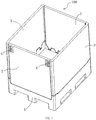
- Figure 1 shows a perspective structural view of a general collapsible container.
- a collapsible container 100 comprises a base 1, two pairs of side walls 2 and 3, and locks 4 for maintaining the side walls 2 and 3 in erected positions.
- the locks 4 between side walls 2 and 3 are unlocked, then the side walls 2 and 3 are folded towards the interior of the container, so that the height of the container is reduced significantly and the transportation cost is saved.
- Figures 2-7 show the structure of connection between the side wall and the base according to the first embodiment of this invention.
- the side walls 2 and 3 are provided with one or more movable portions 31 at the bottom thereof.
- the side walls 2 and 3 can be disposed in one or more corresponding opening pockets 11 in the base 1 via one or more movable portions 31.
- the side walls 2 and 3 and the base 1 are interconnected via the hinge device between the opening pockets 11 and the movable portions 31.
- the hinge device comprises a connecter 6 with a through hole 62 (round, square, and the like) in the center thereof and hinge pins 61 perpendicular to the axis of the through hole 62 on two or one sides of the connecter.
- the movable portions 31 of the side walls are provided with holes for receiving the hinge pins on the connecter 6, so that the side walls can be rotated around the hinge pins.
- the base 1 is provided with a vertical cylinder 12 in an opening pocket 11 which can pass through the through hole 62 of the connecter, so that the connecter is movable along the central axis of the cylinder 12, i.e. in vertical direction.
- the specific structure of the connecter 6 is shown in figure 3 .
- the connecter is provided with a circular through hole 62 and a hinge pin 61 on each side thereof.
- the two hinge pins 61 are coaxial and perpendicular to the axis of the through hole 62.
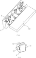
- Figure 4 shows a perspective structural view of the connection portion between the base and the side walls.
- the base 1 is provided with opening pockets 11 and 11a.
- Each of the opening pockets 11 and 11a is provided with grooves 13 on two sides thereof.
- Each of the opening pockets 11 is provided with a cylindrical pin 12 inside thereof.
- the cylindrical pin can pass through the hole 62 of the connecter 6, so that the connecter 6 is movable along the axis of the cylinder pin 12.
- the opening pocket 11a is provided with lateral shoulders 14 on the top thereof and a baffle 15 on the bottom thereof.
- the relative arrangement of the opening pocket 11 and the opening pocket 11a can be changed.
- the left opening pocket can be an opening pocket 11a
- the middle one can be an opening pocket 11.
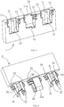
- Figures 5-7 show the structure of the connection portion on the side walls, wherein figure 7 is a partial section view.
- the bottom of the side wall 3 has movable portions 31 and 31a extending therefrom with a ledge 33 at each side thereof.
- the ledge 33 can be cooperated with the groove 13 on the base 1. That is, the ledges 33 can enter into the groove 13 when the side walls 3 are in erected status, so as to restrict a vertical movement of the side wall 3 relative to the base 1 in such status.
- the side of movable portion 31 is provided with a slot 35 in the central portion thereof for receiving the cylinder pin 12 and with a recess 32 in the lower portion thereof.
- the specific structure of the recess 32 is shown in the sectional view of figure 7 .
- the recess has an arc profile 321 at the root for accommodating the hinge pin 62 of the connecter.
- a narrowed segment 322 is provided between the profile 321 and the opening of the recess 32, so that the hinge pin 62 in the recess 32 can not drop off easily.
- the movable portion 31a is provided with an inclined ramp 34 and a recess 36 above the ramp 34.
- the vertical distance H 1 from the ramp 34 to the axis of the hinge pin 62 of the connecter 6 is no greater than the vertical H 2 from the axis of the hinge pin 62 to the end surface of the shoulder 14 on the base 1 (see figure 11 ).
- the movable portion 31a is provided with a slot 37 at the bottom end on the other side. The slot 37 allows the baffle 15 to be received therein when the side walls 2 and 3 are erected (see figure 11 ), so as to restrict the side walls 2 and 3 from moving inwardly when suffering external force.
- the hinge pins 61 of the connecter 6 can be mounted in the recess 32 of the side walls 3 in many ways, for example, through interference fit by pressing the hinge pins 61 into the recess 32 due to the flexibility of the plastic member, or forming a ramp on the hinge pin 61 at the non-working angle position with a width less than the width of the narrowed segment 322, or dividing the hinge pin 61 into separate components so that they can be inserted laterally.
- the purpose of the above solutions is that the side walls 2 and 3 can be rotated relative to the connecter 6 and the connecter 6 is interconnected with the side walls 2 and 3 when the side walls are in working position.
- the shapes of the holes 62 in the connecter 6 and the cylinder pin on the base 1 can vary in practice, such as square, oval, and the like.
- the side walls can also be connected to the base 1 by various means such as consequent assembling or inserting inserts, as long as side walls 2 and 3 can move relative to the base 1 up and down in non-erected status and maintain connection with the base 1 in a certain movement distance.
- Figures 9 and 10 show the positions in the base 1 of the movable portions 31 of opposite side walls 2 and 3 in different folding sequences. Taking the side wall 2 as an example, both earlier and later folding sequences allow it overlaps with the base 1 flatly and snugly. The difference is that, the movable portion of the side wall 2 which is folded later in the base 1 offsets upwardly a distance by about the thickness of one side wall.
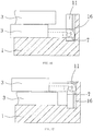
- figure 11 shows the relationship among features during the rotation of the side walls relative to the base.
- the side wall 3 as an example, it is known that the above structure enables the movable portion 31 to move up and down in the opening pocket 11 of the base 1.
- the side wall 3 can be rotated around the hinge pins 61 of the connecter 6, as shown in figures.
- the distance from the ramp 34 on the movable portion 31 to the axis of the hinge pins 61 is set as 7mm, and the vertical distance from the end surface on the shoulders 14 of the opening pocket 11 to the axis of the hinge pins 61 is set as 7.5mm, then when the side wall 3 is rotated by a certain angle for example 60 degrees, the ramp 34 is substantially in an erected status, enabling the movable portion 31 to avoid the shoulders 14. If it is required to detach the side wall 3, the base 1 is disconnected with the side wall by only pulling the side wall 3 upwardly further so that it can be disengaged from the opening pocket 11.
- the shoulders 14 can always restrict the movable portions 31 from leaving the opening pockets 11 in the base 1, so as to ensure the connection between the side wall 3 and the base during folding and unfolding.
- the ledges 33 can be received in the grooves 13 when the side wall 3 is in erected status, so as to restrict the side wall 3 from moving in vertical direction relative to the base 1. Further, the ledges 33 can be disengaged from the grooves 13 by only rotating the side wall 3 inwardly.
- the recess 36 can engage with the shoulders 14 in the same way, so as to improve the locking strength between the side wall 3 and the base 1 in vertical direction.
- Figures 12-17 show the structure of connection between the side wall and the base according to the second embodiment of this invention.
- the difference between this embodiment and the first embodiment lies in that, the structure enabling the movable portions 31 of the side wall 3 to move up and down in the opening pockets 11 of the base 1 is varied as a straight wall 72 provided on a connecter 7 and a straight slot 16 provided on the base (the corresponding structures in the embodiment shown in figures 2-7 are the hole 62 and the cylindrical pin 11).
- the straight wall 72 can be inserted into the straight slot 16 and moves up and down along it.
- the straight wall 72 is provided on one end of the connecter 7, and the hinge pins 71 are provided on the other end of the connecter 7 and perpendicular to the straight wall 72.
- the remaining features are the same, and the description thereof is not described again.
- the engagement structure between the connecter and the opening pocket of the base can employ other engagement structures other than the hole-cylinder pin and the straight wall-straight slot, provided that the connecter can moves up and down in vertical direction in the opening pockets of the base.
- the opening pockets of the base are provided with guiding device
- the connecters are provided with sliding device engaging with the guiding device, enabling the sliding device on the connecter to move up and down in vertical direction along the guiding device in the opening pockets.
- the side walls of the collapsible container according to this invention When folded, the side walls of the collapsible container according to this invention will not inclined relative to the base.
- the collapsible container of the invention can be detached or folded in any consequences without tool.
- This invention is suitable for large containers, especially large collapsible transferring containers.
- the large container herein is a container with volume over 800L.
Description
- The invention relates to a collapsible container, in particular a hinge structure of the collapsible container.
- The empty containers or boxes with fixed side walls need considerable storage space. Therefore, the existing container comprises collapsible side walls to reduce the corresponding volume in unloaded status. Most of these collapsible containers comprise a base in form of rectangular plate structure, wherein the collapsible side walls are coupled to the edges of the base by hinges. When the side walls are in unfolded position, the side walls are coupled to each other via interlocking buckle engagement, wherein engaging latches on one pair of opposite side walls are engaged to the engaging hooks on the other pair of opposite side walls.
- For many containers, the side walls are configured to be higher than half of the width of the base, thus the opposite side walls will be overlapped when they are folded towards each other. Therefore, the side wall which is folded later will extend beyond the edge of the side wall which is folded first and will be not parallel to the base but angled. In other word, the side wall folded later is in an inclined position. When a plurality of containers are stacked one above another, corresponding bending movement of the upper side wall positioned angularly occurs, which will cause a damage or deform over time. For such containers, another defect is that several collapsed containers can not be stacked in a stable way.
- In order to overcome these defects, the side walls are connected to the shaft with different heights on the sides of the base, so that the side walls are connected to the base at different heights, wherein the side walls connected at lower positions are folded firstly, then the side walls connected at higher positions are folded subsequently, and when two side walls are in folded positions, they are arranged parallel to the base.
- However, the height of the opposite side walls are different, which increases the cost of manufacturing and maintaining. Further, the workers must pay more attention during the operation which will affect the efficiency to some extend, since the folding work should be executed sequentially. It needs a more advanced alternative solution to solve this problem.
- The object of this invention is to provide a collapsible container which can be assembled and disassembled without tool and can be folded in any consequences.
- In order to achieve the above object, this invention provides a collapsible container, comprising a base and two pairs of opposite side walls, wherein:
- each of the side walls is provided with one or more movable portions extending from the bottom of the side walls, and the base is provided with one or more opening pockets, wherein the side walls are positioned in the corresponding opening pockets on the base via the movable portions;
- a hinge device is provided between the movable portions and the opening pockets, wherein the hinge device comprises: hinge holes provided in the movable portions of the side walls; a guiding device provided in the opening pockets of the base; and a connecter provided with hinge pins and a sliding device to be engaged with the guiding device; wherein,
- the connecter is movable up and down in vertical direction along the guiding device in the opening pockets via the sliding device, and the hinge pins are disposed in the hinge holes and enable the side walls to be rotated around the hinge pins.
- Preferably, according to the collapsible container of the invention, an interlocking device is disposed between at least one side wall and the base, so that the interlocking device prevents the side wall from moving in vertical direction relative to the base when the side wall is in erected status relative to the base, and the interlocking device between the side wall and the base is releasable through the rotation of the side wall around the hinge pins.
- According to one embodiment of the invention, the sliding device on the connecter is a through hole in the center thereof; the hinge pins are located perpendicular to the axis of the through hole on one or two sides of the connecter; and the guiding device in the opening pockets of the base is a vertical cylinder capable of passing through the through hole, so that the connecter is movable along the axis of the cylinder.
- According to anther embodiment of the invention, the sliding device of the connecter is a straight wall disposed on one end of the connecter; the hinge pins are located at the other end of the connecter and perpendicular to the straight wall; and the guiding device in the opening pocket is a straight slot perpendicular to a plane of the base, wherein the straight wall is slidable along the straight slot, so that the connecter is movable along the straight slot.
- Preferably, the opening pockets in the base are provided with lateral shoulders with a lateral distance H2 from the end surface thereof to the axis of the hinge pin; wherein a distance from the external edge of the movable portion of the side wall disposed in the opening pocket to the axis of the hinge pin is larger than H2.
- Preferably, the movable portion is provided with a recess at the lower portion thereof; the hinge hole is an arc profile disposed at the root of the recess; and a narrowed segment is provided between the arc profile and an opening of the recess, so as to prevent the hinge pin from easily dropping off after entering into the recess.
- Preferably, the interlocking device comprises ledges provided on the two sides of the movable portion and grooves on the base for engaging with the ledges, so as to restrict a movement of the side wall in vertical direction relative to the base when the side wall is in erected status.
- Preferably, the movable portion is provided with an inclined ramp, when connected, the vertical distance from the ramp to the axis of the hinge pin of the connecter is no greater than the vertical distance H2 from the axis of the hinge pin to an end surface of the shoulders on the base.
- Preferably, the movable portion is provided with a slot at a bottom end on one side thereof, and the base is provided with a baffle, wherein the slot allows the baffle of the base to be received therein when the side walls are erected, so as to restrict the side walls from moving inwardly when suffering external force.
- Preferably, the collapsible container is IBC.
- When folded, the side walls of the collapsible container according to this invention will not inclined relative to the base. In addition, the collapsible container of the invention can be detached or folded in any consequences without tool.
-
-
Figure 1 shows a perspective structural view of a general collapsible container. -
Figure 2 shows a structure of connection between the side wall and the base according to the first embodiment of this invention. -
Figure 3 is a perspective structural view of the connecter infigure 2 . -
Figure 4 shows a perspective structural view of the connection portion of the base according to the first embodiment of this invention. -
Figures 5-6 show a perspective structural view of the connection portion of the side wall according to the first embodiment of this invention. -
Figure 7 is a partial section view along line A-A infigure 5 of the connection portion of the side wall. -
Figure 8 shows an assembling relationship among the side wall, the base and the connecters. -
Figures 9 and 10 show the positions of moving portions extending from opposite side walls on the base when the opposite side walls are folded in different sequences. -
Figure 11 shows an unfolding process of the side wall. -
Figures 12-15 show the structure of connection between the side wall and the base according to the second embodiment of this invention. -
Figures 16-17 are the structural views of collapsed container with side walls folded in different sequences respectively. - The preferred embodiments of the invention will be described in detail with the reference to the drawing in the following, in order to more clearly understand the purpose, the features and advantages of the present invention. It should be understood that the embodiments shown in the drawings are not to limit the scope of the invention, but merely to illustrate the technical solution of the present invention.
-
Figure 1 shows a perspective structural view of a general collapsible container. As shown infigure 1 , acollapsible container 100 comprises abase 1, two pairs ofside walls locks 4 for maintaining theside walls locks 4 betweenside walls side walls -
Figures 2-7 show the structure of connection between the side wall and the base according to the first embodiment of this invention. As shown infigures 2-5 , theside walls movable portions 31 at the bottom thereof. Theside walls opening pockets 11 in thebase 1 via one or moremovable portions 31. Then, theside walls base 1 are interconnected via the hinge device between theopening pockets 11 and themovable portions 31. The hinge device comprises aconnecter 6 with a through hole 62 (round, square, and the like) in the center thereof and hingepins 61 perpendicular to the axis of the throughhole 62 on two or one sides of the connecter. Themovable portions 31 of the side walls are provided with holes for receiving the hinge pins on theconnecter 6, so that the side walls can be rotated around the hinge pins. Thebase 1 is provided with avertical cylinder 12 in anopening pocket 11 which can pass through the throughhole 62 of the connecter, so that the connecter is movable along the central axis of thecylinder 12, i.e. in vertical direction. - The specific structure of the
connecter 6 is shown infigure 3 . The connecter is provided with a circular throughhole 62 and ahinge pin 61 on each side thereof. The twohinge pins 61 are coaxial and perpendicular to the axis of the throughhole 62. -
Figure 4 shows a perspective structural view of the connection portion between the base and the side walls. As shown infigure 4 , thebase 1 is provided withopening pockets opening pockets grooves 13 on two sides thereof. Each of theopening pockets 11 is provided with acylindrical pin 12 inside thereof. The cylindrical pin can pass through thehole 62 of theconnecter 6, so that theconnecter 6 is movable along the axis of thecylinder pin 12. Theopening pocket 11a is provided withlateral shoulders 14 on the top thereof and abaffle 15 on the bottom thereof. It shall be noted that, the relative arrangement of theopening pocket 11 and theopening pocket 11a can be changed. For example, infigure 4 , the left opening pocket can be anopening pocket 11a, and the middle one can be anopening pocket 11. -
Figures 5-7 show the structure of the connection portion on the side walls, whereinfigure 7 is a partial section view. As shown infigures 5-7 , the bottom of theside wall 3 hasmovable portions ledge 33 at each side thereof. Theledge 33 can be cooperated with thegroove 13 on thebase 1. That is, theledges 33 can enter into thegroove 13 when theside walls 3 are in erected status, so as to restrict a vertical movement of theside wall 3 relative to thebase 1 in such status. The side ofmovable portion 31 is provided with aslot 35 in the central portion thereof for receiving thecylinder pin 12 and with arecess 32 in the lower portion thereof. The specific structure of therecess 32 is shown in the sectional view offigure 7 . The recess has anarc profile 321 at the root for accommodating thehinge pin 62 of the connecter. A narrowedsegment 322 is provided between theprofile 321 and the opening of therecess 32, so that thehinge pin 62 in therecess 32 can not drop off easily. - The
movable portion 31a is provided with aninclined ramp 34 and arecess 36 above theramp 34. When connected, the vertical distance H1 from theramp 34 to the axis of thehinge pin 62 of theconnecter 6 is no greater than the vertical H2 from the axis of thehinge pin 62 to the end surface of theshoulder 14 on the base 1 (seefigure 11 ). In addition, as shown infigure 7 , themovable portion 31a is provided with aslot 37 at the bottom end on the other side. Theslot 37 allows thebaffle 15 to be received therein when theside walls figure 11 ), so as to restrict theside walls - The cooperation among the
side walls base 1 and theconnecter 6 is shown infigure 8 . It shall be noted that, the hinge pins 61 of theconnecter 6 can be mounted in therecess 32 of theside walls 3 in many ways, for example, through interference fit by pressing the hinge pins 61 into therecess 32 due to the flexibility of the plastic member, or forming a ramp on thehinge pin 61 at the non-working angle position with a width less than the width of the narrowedsegment 322, or dividing thehinge pin 61 into separate components so that they can be inserted laterally. The purpose of the above solutions is that theside walls connecter 6 and theconnecter 6 is interconnected with theside walls holes 62 in theconnecter 6 and the cylinder pin on thebase 1 can vary in practice, such as square, oval, and the like. The side walls can also be connected to thebase 1 by various means such as consequent assembling or inserting inserts, as long asside walls base 1 up and down in non-erected status and maintain connection with thebase 1 in a certain movement distance. -
Figures 9 and 10 show the positions in thebase 1 of themovable portions 31 ofopposite side walls side wall 2 as an example, both earlier and later folding sequences allow it overlaps with thebase 1 flatly and snugly. The difference is that, the movable portion of theside wall 2 which is folded later in thebase 1 offsets upwardly a distance by about the thickness of one side wall. - Other than
figures 9 and 10 ,figure 11 shows the relationship among features during the rotation of the side walls relative to the base. Taking theside wall 3 as an example, it is known that the above structure enables themovable portion 31 to move up and down in theopening pocket 11 of thebase 1. Theside wall 3 can be rotated around the hinge pins 61 of theconnecter 6, as shown in figures. Assuming the distance from theramp 34 on themovable portion 31 to the axis of the hinge pins 61 is set as 7mm, and the vertical distance from the end surface on theshoulders 14 of theopening pocket 11 to the axis of the hinge pins 61 is set as 7.5mm, then when theside wall 3 is rotated by a certain angle for example 60 degrees, theramp 34 is substantially in an erected status, enabling themovable portion 31 to avoid theshoulders 14. If it is required to detach theside wall 3, thebase 1 is disconnected with the side wall by only pulling theside wall 3 upwardly further so that it can be disengaged from theopening pocket 11. When theside wall 3 is normally rotating within other angle range, theshoulders 14 can always restrict themovable portions 31 from leaving the opening pockets 11 in thebase 1, so as to ensure the connection between theside wall 3 and the base during folding and unfolding. Theledges 33 can be received in thegrooves 13 when theside wall 3 is in erected status, so as to restrict theside wall 3 from moving in vertical direction relative to thebase 1. Further, theledges 33 can be disengaged from thegrooves 13 by only rotating theside wall 3 inwardly. Therecess 36 can engage with theshoulders 14 in the same way, so as to improve the locking strength between theside wall 3 and thebase 1 in vertical direction. -
Figures 12-17 show the structure of connection between the side wall and the base according to the second embodiment of this invention. As shown infigures 12-17 , the difference between this embodiment and the first embodiment lies in that, the structure enabling themovable portions 31 of theside wall 3 to move up and down in the opening pockets 11 of thebase 1 is varied as astraight wall 72 provided on aconnecter 7 and astraight slot 16 provided on the base (the corresponding structures in the embodiment shown infigures 2-7 are thehole 62 and the cylindrical pin 11). Thestraight wall 72 can be inserted into thestraight slot 16 and moves up and down along it. Thestraight wall 72 is provided on one end of theconnecter 7, and the hinge pins 71 are provided on the other end of theconnecter 7 and perpendicular to thestraight wall 72. The remaining features are the same, and the description thereof is not described again. - It should be noted that, in the above embodiments, the engagement structure between the connecter and the opening pocket of the base can employ other engagement structures other than the hole-cylinder pin and the straight wall-straight slot, provided that the connecter can moves up and down in vertical direction in the opening pockets of the base. Indeed, it can works provided that the opening pockets of the base are provided with guiding device, and the connecters are provided with sliding device engaging with the guiding device, enabling the sliding device on the connecter to move up and down in vertical direction along the guiding device in the opening pockets.
- When folded, the side walls of the collapsible container according to this invention will not inclined relative to the base. In addition, the collapsible container of the invention can be detached or folded in any consequences without tool.
- This invention is suitable for large containers, especially large collapsible transferring containers. The large container herein is a container with volume over 800L.
- The preferred embodiments of the present invention have been described in detail above. However, it should be understood that after reading the foregoing teachings of the present invention, those skilled in the art may make various modifications.
Claims (9)
- A collapsible container (100), comprising a base (1) and two pairs of opposite side walls (2, 3), wherein:each of the side walls (2, 3) is provided with one or more movable portions (31, 31a) extending from the bottom of the side walls (2, 3), and the base (1) is provided with one or more opening pockets (11,11a), wherein the side walls (2, 3) are positioned in the corresponding opening pockets (11,11a) on the base (1) via the movable portions (31, 31a);a hinge device is provided between the movable portions (31) and the opening pockets (11), characterised in that the hinge device comprises: hinge holes (321) provided in the movable portions (31) of the side walls (2, 3); a guiding device (12, 16) provided in the opening pockets (11) of the base (1); and a connecter (6, 7) provided with hinge pins (61, 71) and a sliding device (62, 72) to be engaged with the guiding device (12, 16); wherein,the connecter (6, 7) is movable up and down in vertical direction along the guiding device (12, 16) in the opening pockets (11) via the sliding device (62, 72), and the hinge pins (61, 71) are disposed in the hinge holes (321) and enable the side walls (2, 3) to be rotated around the hinge pins (61, 71).
- The collapsible container (100) according to claim 1, wherein an interlocking device (33, 13) is disposed between at least one side wall (2, 3) and the base so that the interlocking device (33, 13) prevents the side wall (2, 3) from moving in vertical direction relative to the base (1) when the side wall (2, 3) is in erected status relative to the base (1), and the interlocking device (33, 13) between the side wall (2, 3) and the base (1) is releasable through the rotation of the side wall (2, 3) around the hinge pins (61, 71).
- The collapsible container (100) according to claim 1, wherein the sliding device on the connecter (6) is a through hole in the center thereof; the hinge pins (61) are located perpendicular to the axis of the through hole on one or two sides of the connecter (6); and the guiding device in the opening pockets (11) of the base is a vertical cylinder (12) capable of passing through the through hole (62), so that the connecter (6) is movable along the axis of the cylinder (12).
- The collapsible container (100) according to claim 1, wherein the sliding device of the connecter (7) is a straight wall (72) disposed on one end of the connecter (7); the hinge pins (71) are located at the other end of the connecter (7) and perpendicular to the straight wall (72); and the guiding device in the opening pocket (11) is a straight slot (16) perpendicular to a plane of the base (1), wherein the straight wall (72) is slidable along the straight slot (16), so that the connecter (7) is movable along the straight slot (16).
- The collapsible container (100) according to claim 1, wherein the opening pockets (11) in the base (1) are provided with lateral shoulders (14) with a lateral distance H2 from the end surface thereof to the axis of the hinge pins (61, 71); wherein a distance from the external edge of the movable portion (31) of the side walls (2, 3) disposed in the opening pocket (11) to the axis of the hinge pin (61, 71) is larger than H2.
- The collapsible container (100) according to claim 1, wherein the movable portion (31) is provided with a recess (32) at the lower portion thereof; the hinge hole is an arc profile (321) disposed at the root of the recess (32); and a narrowed segment (322) is provided between the arc profile (321) and an opening of the recess (32), so as to prevent the hinge pins (61, 71) from easily dropping off after entering into the recess (32).
- The collapsible container (100) according to claim 2, wherein the interlocking device comprises ledges (33) provided on the two sides of the movable portion (31) and grooves (13) on the base (1) for engaging with the ledges (33), so as to restrict a movement of the side wall (2, 3) in vertical direction relative to the base (1) when the side wall (2, 3) is in erected status.
- The collapsible container (100) according to claim 1, wherein the movable portion (31a) is provided with an inclined ramp (34), when connected, the vertical distance from the ramp (34) to the axis of the hinge pins (61, 71) of the connecter (6, 7) is no greater than the vertical distance H2 from the axis of the hinge pin (61, 71) to an end surface of the shoulders (14) on the base (1).
- The collapsible container (100) according to claim 1, wherein the movable portion (31a) is provided with a slot (37) at a bottom end on one side thereof, and the base (1) is provided with a baffle (15), wherein the slot (37) allows the baffle (15) of the base (1) to be received therein when the side walls (2, 3) are erected, so as to restrict the side walls (2, 3) from moving inwardly when suffering external force.
Applications Claiming Priority (2)
| Application Number | Priority Date | Filing Date | Title |
|---|---|---|---|
| CN201310501224.6A CN103693264B (en) | 2013-10-22 | 2013-10-22 | A kind of collapsible container |
| PCT/CN2014/089174 WO2015058693A1 (en) | 2013-10-22 | 2014-10-22 | Foldable container |
Publications (3)
| Publication Number | Publication Date |
|---|---|
| EP3061708A1 EP3061708A1 (en) | 2016-08-31 |
| EP3061708A4 EP3061708A4 (en) | 2017-06-28 |
| EP3061708B1 true EP3061708B1 (en) | 2018-12-05 |
Family
ID=50354970
Family Applications (1)
| Application Number | Title | Priority Date | Filing Date |
|---|---|---|---|
| EP14856236.6A Active EP3061708B1 (en) | 2013-10-22 | 2014-10-22 | Collapsible container |
Country Status (4)
| Country | Link |
|---|---|
| US (1) | US9919833B2 (en) |
| EP (1) | EP3061708B1 (en) |
| CN (1) | CN103693264B (en) |
| WO (1) | WO2015058693A1 (en) |
Families Citing this family (14)
| Publication number | Priority date | Publication date | Assignee | Title |
|---|---|---|---|---|
| CN103693264B (en) * | 2013-10-22 | 2016-08-17 | 上海鸿研物流技术有限公司 | A kind of collapsible container |
| CN104163279B (en) * | 2014-07-22 | 2016-06-01 | 上海鸿研物流技术有限公司 | Collapsible container and lockout mechanism thereof |
| CN104554980B (en) * | 2014-12-16 | 2016-09-14 | 上海鸿研物流技术有限公司 | Collapsible container |
| CN104944012B (en) * | 2015-05-07 | 2018-02-23 | 上海鸿研物流技术有限公司 | Collapsible container |
| US10065763B2 (en) | 2016-09-15 | 2018-09-04 | Arena Packaging, Llc | Wall latching system |
| ES2948007T3 (en) * | 2017-07-20 | 2023-08-25 | Kidkraft Inc | Foldable accordion play structure with easy assembly device |
| CN108482797B (en) * | 2018-04-13 | 2024-02-27 | 上海鸿研物流技术有限公司 | Folding box |
| CN109835570B (en) * | 2019-02-27 | 2024-02-27 | 上海鸿研物流技术有限公司 | Foldable container |
| CN112319994A (en) * | 2019-08-05 | 2021-02-05 | 无锡市正浩包装材料有限公司 | Wood tray with enclosure |
| RU195106U1 (en) * | 2019-10-01 | 2020-01-15 | Геннадий Сергеевич Бубенчиков | Multi-section container for separate waste collection |
| US10905214B1 (en) | 2020-02-05 | 2021-02-02 | ELK Promotions, Inc. | Clothing container and rack |
| CN111846515A (en) * | 2020-08-03 | 2020-10-30 | 上海鸿研物流技术有限公司 | Folding container |
| WO2022056462A2 (en) * | 2020-09-14 | 2022-03-17 | Rehrig Pacific Company | Crate with retractable wall |
| US11903483B1 (en) * | 2022-08-17 | 2024-02-20 | Protrend Co., Ltd. | Foldable storage device |
Family Cites Families (14)
| Publication number | Priority date | Publication date | Assignee | Title |
|---|---|---|---|---|
| EP0655392A3 (en) * | 1993-11-29 | 1995-08-02 | Otto Ind Inc | Collapsible container. |
| CA2229820C (en) * | 1995-06-07 | 2006-05-30 | Ropak Corporation | Collapsible container with hinged sidewalls |
| AU2012216576A1 (en) * | 2005-05-17 | 2012-09-20 | Rehrig Pacific Company | Pallet |
| DE102009049185A1 (en) * | 2009-04-15 | 2011-01-05 | Ifco Systems Gmbh | Crate with foldable side walls with stable sidewall structure |
| DE102009049103A1 (en) * | 2009-04-15 | 2010-11-04 | Ifco Systems Gmbh | Crate with foldable and removable outer walls |
| WO2010118758A1 (en) * | 2009-04-15 | 2010-10-21 | Ifco Systems Gmbh | Container having folding side wall |
| US8381929B2 (en) * | 2010-04-27 | 2013-02-26 | Ifco Systems Gmbh | Container with side walls foldable on top of one another |
| CN201737375U (en) * | 2010-08-18 | 2011-02-09 | 台州印山制刷有限公司 | Door end structure of bulk container |
| EP2500495B1 (en) * | 2011-03-14 | 2014-05-07 | K. Hartwall Oy AB | Hinge module, hinge assembly and roll container |
| CH704660A2 (en) * | 2011-03-17 | 2012-09-28 | Utz Georg Holding Ag | Folding transport and storage containers. |
| CN102502124B (en) * | 2011-09-29 | 2013-07-24 | 上海鸿润科技有限公司 | Hinge system and foldable container |
| CN102530348B (en) * | 2012-02-13 | 2014-07-30 | 上海鸿研物流技术有限公司 | Hidden hinge and container using same |
| CN203568066U (en) * | 2013-10-22 | 2014-04-30 | 上海鸿研物流技术有限公司 | Foldable container |
| CN103693264B (en) * | 2013-10-22 | 2016-08-17 | 上海鸿研物流技术有限公司 | A kind of collapsible container |
-
2013
- 2013-10-22 CN CN201310501224.6A patent/CN103693264B/en active Active
-
2014
- 2014-10-22 WO PCT/CN2014/089174 patent/WO2015058693A1/en active Application Filing
- 2014-10-22 EP EP14856236.6A patent/EP3061708B1/en active Active
- 2014-10-22 US US15/031,615 patent/US9919833B2/en active Active
Non-Patent Citations (1)
| Title |
|---|
| None * |
Also Published As
| Publication number | Publication date |
|---|---|
| US9919833B2 (en) | 2018-03-20 |
| CN103693264B (en) | 2016-08-17 |
| WO2015058693A1 (en) | 2015-04-30 |
| EP3061708A4 (en) | 2017-06-28 |
| US20160272364A1 (en) | 2016-09-22 |
| CN103693264A (en) | 2014-04-02 |
| EP3061708A1 (en) | 2016-08-31 |
Similar Documents
| Publication | Publication Date | Title |
|---|---|---|
| EP3061708B1 (en) | Collapsible container | |
| EP2765095B1 (en) | Hinge system and foldable container | |
| US8727158B2 (en) | Bulk container with angled side wall to base installation | |
| CA2797455C (en) | Container with side walls foldable on top of one another | |
| EP3293127B1 (en) | Foldable container | |
| CN201808724U (en) | Pallet box | |
| US20140326719A1 (en) | Detachable container | |
| US11235905B2 (en) | Frame and pallet coaming box | |
| BRPI1006636B1 (en) | BOX WITH FOLDING SIDE WALLS AND SELF-LOCKING | |
| US8684209B2 (en) | Foldable and overlappable carrier box | |
| EP4082927B1 (en) | Folding box | |
| KR20170065359A (en) | A locking device for containers | |
| CA2902680C (en) | Collapsible container | |
| CN203568066U (en) | Foldable container | |
| US8720719B2 (en) | Foldable transport and storage container | |
| CN102159466A (en) | Large container | |
| CN212710519U (en) | Tray box | |
| CN205114159U (en) | Apex angle spare and public body, parent thereof | |
| CN219920702U (en) | Detachable row framework and bed | |
| CN219155001U (en) | Assembled turnover case with stop gear | |
| JP2016199296A (en) | Folding container | |
| CN218662849U (en) | Folding packaging structure | |
| JP2020019549A (en) | Folding container | |
| CN215156553U (en) | Folding basket | |
| CN209814563U (en) | Self-locking structure and foldable tray box with same |
Legal Events
| Date | Code | Title | Description |
|---|---|---|---|
| PUAI | Public reference made under article 153(3) epc to a published international application that has entered the european phase |
Free format text: ORIGINAL CODE: 0009012 |
|
| 17P | Request for examination filed |
Effective date: 20160520 |
|
| AK | Designated contracting states |
Kind code of ref document: A1 Designated state(s): AL AT BE BG CH CY CZ DE DK EE ES FI FR GB GR HR HU IE IS IT LI LT LU LV MC MK MT NL NO PL PT RO RS SE SI SK SM TR |
|
| AX | Request for extension of the european patent |
Extension state: BA ME |
|
| DAX | Request for extension of the european patent (deleted) | ||
| A4 | Supplementary search report drawn up and despatched |
Effective date: 20170530 |
|
| RIC1 | Information provided on ipc code assigned before grant |
Ipc: B65D 19/18 20060101AFI20170523BHEP |
|
| REG | Reference to a national code |
Ref country code: DE Ref legal event code: R079 Ref document number: 602014037617 Country of ref document: DE Free format text: PREVIOUS MAIN CLASS: B65D0088520000 Ipc: B65D0019180000 |
|
| GRAP | Despatch of communication of intention to grant a patent |
Free format text: ORIGINAL CODE: EPIDOSNIGR1 |
|
| STAA | Information on the status of an ep patent application or granted ep patent |
Free format text: STATUS: GRANT OF PATENT IS INTENDED |
|
| RIC1 | Information provided on ipc code assigned before grant |
Ipc: B65D 19/18 20060101AFI20180531BHEP |
|
| INTG | Intention to grant announced |
Effective date: 20180622 |
|
| GRAS | Grant fee paid |
Free format text: ORIGINAL CODE: EPIDOSNIGR3 |
|
| GRAA | (expected) grant |
Free format text: ORIGINAL CODE: 0009210 |
|
| STAA | Information on the status of an ep patent application or granted ep patent |
Free format text: STATUS: THE PATENT HAS BEEN GRANTED |
|
| AK | Designated contracting states |
Kind code of ref document: B1 Designated state(s): AL AT BE BG CH CY CZ DE DK EE ES FI FR GB GR HR HU IE IS IT LI LT LU LV MC MK MT NL NO PL PT RO RS SE SI SK SM TR |
|
| REG | Reference to a national code |
Ref country code: GB Ref legal event code: FG4D |
|
| REG | Reference to a national code |
Ref country code: CH Ref legal event code: EP |
|
| REG | Reference to a national code |
Ref country code: AT Ref legal event code: REF Ref document number: 1072753 Country of ref document: AT Kind code of ref document: T Effective date: 20181215 |
|
| REG | Reference to a national code |
Ref country code: IE Ref legal event code: FG4D |
|
| REG | Reference to a national code |
Ref country code: DE Ref legal event code: R096 Ref document number: 602014037617 Country of ref document: DE |
|
| REG | Reference to a national code |
Ref country code: NL Ref legal event code: MP Effective date: 20181205 |
|
| REG | Reference to a national code |
Ref country code: AT Ref legal event code: MK05 Ref document number: 1072753 Country of ref document: AT Kind code of ref document: T Effective date: 20181205 |
|
| REG | Reference to a national code |
Ref country code: LT Ref legal event code: MG4D |
|
| PG25 | Lapsed in a contracting state [announced via postgrant information from national office to epo] |
Ref country code: ES Free format text: LAPSE BECAUSE OF FAILURE TO SUBMIT A TRANSLATION OF THE DESCRIPTION OR TO PAY THE FEE WITHIN THE PRESCRIBED TIME-LIMIT Effective date: 20181205 Ref country code: LV Free format text: LAPSE BECAUSE OF FAILURE TO SUBMIT A TRANSLATION OF THE DESCRIPTION OR TO PAY THE FEE WITHIN THE PRESCRIBED TIME-LIMIT Effective date: 20181205 Ref country code: HR Free format text: LAPSE BECAUSE OF FAILURE TO SUBMIT A TRANSLATION OF THE DESCRIPTION OR TO PAY THE FEE WITHIN THE PRESCRIBED TIME-LIMIT Effective date: 20181205 Ref country code: NO Free format text: LAPSE BECAUSE OF FAILURE TO SUBMIT A TRANSLATION OF THE DESCRIPTION OR TO PAY THE FEE WITHIN THE PRESCRIBED TIME-LIMIT Effective date: 20190305 Ref country code: BG Free format text: LAPSE BECAUSE OF FAILURE TO SUBMIT A TRANSLATION OF THE DESCRIPTION OR TO PAY THE FEE WITHIN THE PRESCRIBED TIME-LIMIT Effective date: 20190305 Ref country code: FI Free format text: LAPSE BECAUSE OF FAILURE TO SUBMIT A TRANSLATION OF THE DESCRIPTION OR TO PAY THE FEE WITHIN THE PRESCRIBED TIME-LIMIT Effective date: 20181205 Ref country code: LT Free format text: LAPSE BECAUSE OF FAILURE TO SUBMIT A TRANSLATION OF THE DESCRIPTION OR TO PAY THE FEE WITHIN THE PRESCRIBED TIME-LIMIT Effective date: 20181205 Ref country code: AT Free format text: LAPSE BECAUSE OF FAILURE TO SUBMIT A TRANSLATION OF THE DESCRIPTION OR TO PAY THE FEE WITHIN THE PRESCRIBED TIME-LIMIT Effective date: 20181205 |
|
| PG25 | Lapsed in a contracting state [announced via postgrant information from national office to epo] |
Ref country code: AL Free format text: LAPSE BECAUSE OF FAILURE TO SUBMIT A TRANSLATION OF THE DESCRIPTION OR TO PAY THE FEE WITHIN THE PRESCRIBED TIME-LIMIT Effective date: 20181205 Ref country code: SE Free format text: LAPSE BECAUSE OF FAILURE TO SUBMIT A TRANSLATION OF THE DESCRIPTION OR TO PAY THE FEE WITHIN THE PRESCRIBED TIME-LIMIT Effective date: 20181205 Ref country code: RS Free format text: LAPSE BECAUSE OF FAILURE TO SUBMIT A TRANSLATION OF THE DESCRIPTION OR TO PAY THE FEE WITHIN THE PRESCRIBED TIME-LIMIT Effective date: 20181205 Ref country code: GR Free format text: LAPSE BECAUSE OF FAILURE TO SUBMIT A TRANSLATION OF THE DESCRIPTION OR TO PAY THE FEE WITHIN THE PRESCRIBED TIME-LIMIT Effective date: 20190306 |
|
| PG25 | Lapsed in a contracting state [announced via postgrant information from national office to epo] |
Ref country code: NL Free format text: LAPSE BECAUSE OF FAILURE TO SUBMIT A TRANSLATION OF THE DESCRIPTION OR TO PAY THE FEE WITHIN THE PRESCRIBED TIME-LIMIT Effective date: 20181205 |
|
| PG25 | Lapsed in a contracting state [announced via postgrant information from national office to epo] |
Ref country code: PT Free format text: LAPSE BECAUSE OF FAILURE TO SUBMIT A TRANSLATION OF THE DESCRIPTION OR TO PAY THE FEE WITHIN THE PRESCRIBED TIME-LIMIT Effective date: 20190405 Ref country code: CZ Free format text: LAPSE BECAUSE OF FAILURE TO SUBMIT A TRANSLATION OF THE DESCRIPTION OR TO PAY THE FEE WITHIN THE PRESCRIBED TIME-LIMIT Effective date: 20181205 Ref country code: IT Free format text: LAPSE BECAUSE OF FAILURE TO SUBMIT A TRANSLATION OF THE DESCRIPTION OR TO PAY THE FEE WITHIN THE PRESCRIBED TIME-LIMIT Effective date: 20181205 Ref country code: PL Free format text: LAPSE BECAUSE OF FAILURE TO SUBMIT A TRANSLATION OF THE DESCRIPTION OR TO PAY THE FEE WITHIN THE PRESCRIBED TIME-LIMIT Effective date: 20181205 |
|
| PG25 | Lapsed in a contracting state [announced via postgrant information from national office to epo] |
Ref country code: EE Free format text: LAPSE BECAUSE OF FAILURE TO SUBMIT A TRANSLATION OF THE DESCRIPTION OR TO PAY THE FEE WITHIN THE PRESCRIBED TIME-LIMIT Effective date: 20181205 Ref country code: SM Free format text: LAPSE BECAUSE OF FAILURE TO SUBMIT A TRANSLATION OF THE DESCRIPTION OR TO PAY THE FEE WITHIN THE PRESCRIBED TIME-LIMIT Effective date: 20181205 Ref country code: SK Free format text: LAPSE BECAUSE OF FAILURE TO SUBMIT A TRANSLATION OF THE DESCRIPTION OR TO PAY THE FEE WITHIN THE PRESCRIBED TIME-LIMIT Effective date: 20181205 Ref country code: RO Free format text: LAPSE BECAUSE OF FAILURE TO SUBMIT A TRANSLATION OF THE DESCRIPTION OR TO PAY THE FEE WITHIN THE PRESCRIBED TIME-LIMIT Effective date: 20181205 Ref country code: IS Free format text: LAPSE BECAUSE OF FAILURE TO SUBMIT A TRANSLATION OF THE DESCRIPTION OR TO PAY THE FEE WITHIN THE PRESCRIBED TIME-LIMIT Effective date: 20190405 |
|
| REG | Reference to a national code |
Ref country code: DE Ref legal event code: R097 Ref document number: 602014037617 Country of ref document: DE |
|
| PLBE | No opposition filed within time limit |
Free format text: ORIGINAL CODE: 0009261 |
|
| STAA | Information on the status of an ep patent application or granted ep patent |
Free format text: STATUS: NO OPPOSITION FILED WITHIN TIME LIMIT |
|
| PG25 | Lapsed in a contracting state [announced via postgrant information from national office to epo] |
Ref country code: SI Free format text: LAPSE BECAUSE OF FAILURE TO SUBMIT A TRANSLATION OF THE DESCRIPTION OR TO PAY THE FEE WITHIN THE PRESCRIBED TIME-LIMIT Effective date: 20181205 Ref country code: DK Free format text: LAPSE BECAUSE OF FAILURE TO SUBMIT A TRANSLATION OF THE DESCRIPTION OR TO PAY THE FEE WITHIN THE PRESCRIBED TIME-LIMIT Effective date: 20181205 |
|
| 26N | No opposition filed |
Effective date: 20190906 |
|
| PG25 | Lapsed in a contracting state [announced via postgrant information from national office to epo] |
Ref country code: TR Free format text: LAPSE BECAUSE OF FAILURE TO SUBMIT A TRANSLATION OF THE DESCRIPTION OR TO PAY THE FEE WITHIN THE PRESCRIBED TIME-LIMIT Effective date: 20181205 |
|
| PG25 | Lapsed in a contracting state [announced via postgrant information from national office to epo] |
Ref country code: MC Free format text: LAPSE BECAUSE OF FAILURE TO SUBMIT A TRANSLATION OF THE DESCRIPTION OR TO PAY THE FEE WITHIN THE PRESCRIBED TIME-LIMIT Effective date: 20181205 |
|
| REG | Reference to a national code |
Ref country code: CH Ref legal event code: PL |
|
| PG25 | Lapsed in a contracting state [announced via postgrant information from national office to epo] |
Ref country code: LU Free format text: LAPSE BECAUSE OF NON-PAYMENT OF DUE FEES Effective date: 20191022 Ref country code: LI Free format text: LAPSE BECAUSE OF NON-PAYMENT OF DUE FEES Effective date: 20191031 Ref country code: CH Free format text: LAPSE BECAUSE OF NON-PAYMENT OF DUE FEES Effective date: 20191031 |
|
| REG | Reference to a national code |
Ref country code: BE Ref legal event code: MM Effective date: 20191031 |
|
| PG25 | Lapsed in a contracting state [announced via postgrant information from national office to epo] |
Ref country code: BE Free format text: LAPSE BECAUSE OF NON-PAYMENT OF DUE FEES Effective date: 20191031 |
|
| PG25 | Lapsed in a contracting state [announced via postgrant information from national office to epo] |
Ref country code: IE Free format text: LAPSE BECAUSE OF NON-PAYMENT OF DUE FEES Effective date: 20191022 |
|
| PG25 | Lapsed in a contracting state [announced via postgrant information from national office to epo] |
Ref country code: CY Free format text: LAPSE BECAUSE OF FAILURE TO SUBMIT A TRANSLATION OF THE DESCRIPTION OR TO PAY THE FEE WITHIN THE PRESCRIBED TIME-LIMIT Effective date: 20181205 |
|
| PG25 | Lapsed in a contracting state [announced via postgrant information from national office to epo] |
Ref country code: HU Free format text: LAPSE BECAUSE OF FAILURE TO SUBMIT A TRANSLATION OF THE DESCRIPTION OR TO PAY THE FEE WITHIN THE PRESCRIBED TIME-LIMIT; INVALID AB INITIO Effective date: 20141022 Ref country code: MT Free format text: LAPSE BECAUSE OF FAILURE TO SUBMIT A TRANSLATION OF THE DESCRIPTION OR TO PAY THE FEE WITHIN THE PRESCRIBED TIME-LIMIT Effective date: 20181205 |
|
| PG25 | Lapsed in a contracting state [announced via postgrant information from national office to epo] |
Ref country code: MK Free format text: LAPSE BECAUSE OF FAILURE TO SUBMIT A TRANSLATION OF THE DESCRIPTION OR TO PAY THE FEE WITHIN THE PRESCRIBED TIME-LIMIT Effective date: 20181205 |
|
| PGFP | Annual fee paid to national office [announced via postgrant information from national office to epo] |
Ref country code: GB Payment date: 20231020 Year of fee payment: 10 |
|
| PGFP | Annual fee paid to national office [announced via postgrant information from national office to epo] |
Ref country code: FR Payment date: 20231026 Year of fee payment: 10 Ref country code: DE Payment date: 20231020 Year of fee payment: 10 |