EP3061695A1 - Bonding method and device - Google Patents
Bonding method and device Download PDFInfo
- Publication number
- EP3061695A1 EP3061695A1 EP14856703.5A EP14856703A EP3061695A1 EP 3061695 A1 EP3061695 A1 EP 3061695A1 EP 14856703 A EP14856703 A EP 14856703A EP 3061695 A1 EP3061695 A1 EP 3061695A1
- Authority
- EP
- European Patent Office
- Prior art keywords
- pressurization
- film
- bonding
- target object
- mold
- Prior art date
- Legal status (The legal status is an assumption and is not a legal conclusion. Google has not performed a legal analysis and makes no representation as to the accuracy of the status listed.)
- Granted
Links
Images





Classifications
-
- B—PERFORMING OPERATIONS; TRANSPORTING
- B29—WORKING OF PLASTICS; WORKING OF SUBSTANCES IN A PLASTIC STATE IN GENERAL
- B29C—SHAPING OR JOINING OF PLASTICS; SHAPING OF MATERIAL IN A PLASTIC STATE, NOT OTHERWISE PROVIDED FOR; AFTER-TREATMENT OF THE SHAPED PRODUCTS, e.g. REPAIRING
- B29C65/00—Joining or sealing of preformed parts, e.g. welding of plastics materials; Apparatus therefor
- B29C65/48—Joining or sealing of preformed parts, e.g. welding of plastics materials; Apparatus therefor using adhesives, i.e. using supplementary joining material; solvent bonding
-
- B—PERFORMING OPERATIONS; TRANSPORTING
- B29—WORKING OF PLASTICS; WORKING OF SUBSTANCES IN A PLASTIC STATE IN GENERAL
- B29C—SHAPING OR JOINING OF PLASTICS; SHAPING OF MATERIAL IN A PLASTIC STATE, NOT OTHERWISE PROVIDED FOR; AFTER-TREATMENT OF THE SHAPED PRODUCTS, e.g. REPAIRING
- B29C65/00—Joining or sealing of preformed parts, e.g. welding of plastics materials; Apparatus therefor
- B29C65/02—Joining or sealing of preformed parts, e.g. welding of plastics materials; Apparatus therefor by heating, with or without pressure
- B29C65/18—Joining or sealing of preformed parts, e.g. welding of plastics materials; Apparatus therefor by heating, with or without pressure using heated tools
-
- B—PERFORMING OPERATIONS; TRANSPORTING
- B29—WORKING OF PLASTICS; WORKING OF SUBSTANCES IN A PLASTIC STATE IN GENERAL
- B29C—SHAPING OR JOINING OF PLASTICS; SHAPING OF MATERIAL IN A PLASTIC STATE, NOT OTHERWISE PROVIDED FOR; AFTER-TREATMENT OF THE SHAPED PRODUCTS, e.g. REPAIRING
- B29C66/00—General aspects of processes or apparatus for joining preformed parts
- B29C66/006—Preventing damaging, e.g. of the parts to be joined
-
- B—PERFORMING OPERATIONS; TRANSPORTING
- B29—WORKING OF PLASTICS; WORKING OF SUBSTANCES IN A PLASTIC STATE IN GENERAL
- B29C—SHAPING OR JOINING OF PLASTICS; SHAPING OF MATERIAL IN A PLASTIC STATE, NOT OTHERWISE PROVIDED FOR; AFTER-TREATMENT OF THE SHAPED PRODUCTS, e.g. REPAIRING
- B29C66/00—General aspects of processes or apparatus for joining preformed parts
- B29C66/01—General aspects dealing with the joint area or with the area to be joined
- B29C66/05—Particular design of joint configurations
- B29C66/10—Particular design of joint configurations particular design of the joint cross-sections
- B29C66/11—Joint cross-sections comprising a single joint-segment, i.e. one of the parts to be joined comprising a single joint-segment in the joint cross-section
- B29C66/112—Single lapped joints
- B29C66/1122—Single lap to lap joints, i.e. overlap joints
-
- B—PERFORMING OPERATIONS; TRANSPORTING
- B29—WORKING OF PLASTICS; WORKING OF SUBSTANCES IN A PLASTIC STATE IN GENERAL
- B29C—SHAPING OR JOINING OF PLASTICS; SHAPING OF MATERIAL IN A PLASTIC STATE, NOT OTHERWISE PROVIDED FOR; AFTER-TREATMENT OF THE SHAPED PRODUCTS, e.g. REPAIRING
- B29C66/00—General aspects of processes or apparatus for joining preformed parts
- B29C66/01—General aspects dealing with the joint area or with the area to be joined
- B29C66/05—Particular design of joint configurations
- B29C66/20—Particular design of joint configurations particular design of the joint lines, e.g. of the weld lines
- B29C66/24—Particular design of joint configurations particular design of the joint lines, e.g. of the weld lines said joint lines being closed or non-straight
- B29C66/242—Particular design of joint configurations particular design of the joint lines, e.g. of the weld lines said joint lines being closed or non-straight said joint lines being closed, i.e. forming closed contours
- B29C66/2424—Particular design of joint configurations particular design of the joint lines, e.g. of the weld lines said joint lines being closed or non-straight said joint lines being closed, i.e. forming closed contours being a closed polygonal chain
- B29C66/24243—Particular design of joint configurations particular design of the joint lines, e.g. of the weld lines said joint lines being closed or non-straight said joint lines being closed, i.e. forming closed contours being a closed polygonal chain forming a quadrilateral
- B29C66/24244—Particular design of joint configurations particular design of the joint lines, e.g. of the weld lines said joint lines being closed or non-straight said joint lines being closed, i.e. forming closed contours being a closed polygonal chain forming a quadrilateral forming a rectangle
-
- B—PERFORMING OPERATIONS; TRANSPORTING
- B29—WORKING OF PLASTICS; WORKING OF SUBSTANCES IN A PLASTIC STATE IN GENERAL
- B29C—SHAPING OR JOINING OF PLASTICS; SHAPING OF MATERIAL IN A PLASTIC STATE, NOT OTHERWISE PROVIDED FOR; AFTER-TREATMENT OF THE SHAPED PRODUCTS, e.g. REPAIRING
- B29C66/00—General aspects of processes or apparatus for joining preformed parts
- B29C66/40—General aspects of joining substantially flat articles, e.g. plates, sheets or web-like materials; Making flat seams in tubular or hollow articles; Joining single elements to substantially flat surfaces
- B29C66/41—Joining substantially flat articles ; Making flat seams in tubular or hollow articles
- B29C66/43—Joining a relatively small portion of the surface of said articles
-
- B—PERFORMING OPERATIONS; TRANSPORTING
- B29—WORKING OF PLASTICS; WORKING OF SUBSTANCES IN A PLASTIC STATE IN GENERAL
- B29C—SHAPING OR JOINING OF PLASTICS; SHAPING OF MATERIAL IN A PLASTIC STATE, NOT OTHERWISE PROVIDED FOR; AFTER-TREATMENT OF THE SHAPED PRODUCTS, e.g. REPAIRING
- B29C66/00—General aspects of processes or apparatus for joining preformed parts
- B29C66/70—General aspects of processes or apparatus for joining preformed parts characterised by the composition, physical properties or the structure of the material of the parts to be joined; Joining with non-plastics material
- B29C66/72—General aspects of processes or apparatus for joining preformed parts characterised by the composition, physical properties or the structure of the material of the parts to be joined; Joining with non-plastics material characterised by the structure of the material of the parts to be joined
- B29C66/723—General aspects of processes or apparatus for joining preformed parts characterised by the composition, physical properties or the structure of the material of the parts to be joined; Joining with non-plastics material characterised by the structure of the material of the parts to be joined being multi-layered
-
- B—PERFORMING OPERATIONS; TRANSPORTING
- B29—WORKING OF PLASTICS; WORKING OF SUBSTANCES IN A PLASTIC STATE IN GENERAL
- B29C—SHAPING OR JOINING OF PLASTICS; SHAPING OF MATERIAL IN A PLASTIC STATE, NOT OTHERWISE PROVIDED FOR; AFTER-TREATMENT OF THE SHAPED PRODUCTS, e.g. REPAIRING
- B29C66/00—General aspects of processes or apparatus for joining preformed parts
- B29C66/80—General aspects of machine operations or constructions and parts thereof
- B29C66/83—General aspects of machine operations or constructions and parts thereof characterised by the movement of the joining or pressing tools
- B29C66/832—Reciprocating joining or pressing tools
- B29C66/8322—Joining or pressing tools reciprocating along one axis
-
- A—HUMAN NECESSITIES
- A61—MEDICAL OR VETERINARY SCIENCE; HYGIENE
- A61J—CONTAINERS SPECIALLY ADAPTED FOR MEDICAL OR PHARMACEUTICAL PURPOSES; DEVICES OR METHODS SPECIALLY ADAPTED FOR BRINGING PHARMACEUTICAL PRODUCTS INTO PARTICULAR PHYSICAL OR ADMINISTERING FORMS; DEVICES FOR ADMINISTERING FOOD OR MEDICINES ORALLY; BABY COMFORTERS; DEVICES FOR RECEIVING SPITTLE
- A61J1/00—Containers specially adapted for medical or pharmaceutical purposes
- A61J1/05—Containers specially adapted for medical or pharmaceutical purposes for collecting, storing or administering blood, plasma or medical fluids ; Infusion or perfusion containers
- A61J1/10—Bag-type containers
-
- B—PERFORMING OPERATIONS; TRANSPORTING
- B29—WORKING OF PLASTICS; WORKING OF SUBSTANCES IN A PLASTIC STATE IN GENERAL
- B29C—SHAPING OR JOINING OF PLASTICS; SHAPING OF MATERIAL IN A PLASTIC STATE, NOT OTHERWISE PROVIDED FOR; AFTER-TREATMENT OF THE SHAPED PRODUCTS, e.g. REPAIRING
- B29C65/00—Joining or sealing of preformed parts, e.g. welding of plastics materials; Apparatus therefor
- B29C65/48—Joining or sealing of preformed parts, e.g. welding of plastics materials; Apparatus therefor using adhesives, i.e. using supplementary joining material; solvent bonding
- B29C65/4805—Joining or sealing of preformed parts, e.g. welding of plastics materials; Apparatus therefor using adhesives, i.e. using supplementary joining material; solvent bonding characterised by the type of adhesives
- B29C65/481—Non-reactive adhesives, e.g. physically hardening adhesives
- B29C65/4815—Hot melt adhesives, e.g. thermoplastic adhesives
-
- B—PERFORMING OPERATIONS; TRANSPORTING
- B29—WORKING OF PLASTICS; WORKING OF SUBSTANCES IN A PLASTIC STATE IN GENERAL
- B29C—SHAPING OR JOINING OF PLASTICS; SHAPING OF MATERIAL IN A PLASTIC STATE, NOT OTHERWISE PROVIDED FOR; AFTER-TREATMENT OF THE SHAPED PRODUCTS, e.g. REPAIRING
- B29C65/00—Joining or sealing of preformed parts, e.g. welding of plastics materials; Apparatus therefor
- B29C65/48—Joining or sealing of preformed parts, e.g. welding of plastics materials; Apparatus therefor using adhesives, i.e. using supplementary joining material; solvent bonding
- B29C65/4805—Joining or sealing of preformed parts, e.g. welding of plastics materials; Apparatus therefor using adhesives, i.e. using supplementary joining material; solvent bonding characterised by the type of adhesives
- B29C65/483—Reactive adhesives, e.g. chemically curing adhesives
- B29C65/4835—Heat curing adhesives
-
- B—PERFORMING OPERATIONS; TRANSPORTING
- B29—WORKING OF PLASTICS; WORKING OF SUBSTANCES IN A PLASTIC STATE IN GENERAL
- B29C—SHAPING OR JOINING OF PLASTICS; SHAPING OF MATERIAL IN A PLASTIC STATE, NOT OTHERWISE PROVIDED FOR; AFTER-TREATMENT OF THE SHAPED PRODUCTS, e.g. REPAIRING
- B29C65/00—Joining or sealing of preformed parts, e.g. welding of plastics materials; Apparatus therefor
- B29C65/48—Joining or sealing of preformed parts, e.g. welding of plastics materials; Apparatus therefor using adhesives, i.e. using supplementary joining material; solvent bonding
- B29C65/50—Joining or sealing of preformed parts, e.g. welding of plastics materials; Apparatus therefor using adhesives, i.e. using supplementary joining material; solvent bonding using adhesive tape, e.g. thermoplastic tape; using threads or the like
- B29C65/5057—Joining or sealing of preformed parts, e.g. welding of plastics materials; Apparatus therefor using adhesives, i.e. using supplementary joining material; solvent bonding using adhesive tape, e.g. thermoplastic tape; using threads or the like positioned between the surfaces to be joined
-
- B—PERFORMING OPERATIONS; TRANSPORTING
- B29—WORKING OF PLASTICS; WORKING OF SUBSTANCES IN A PLASTIC STATE IN GENERAL
- B29C—SHAPING OR JOINING OF PLASTICS; SHAPING OF MATERIAL IN A PLASTIC STATE, NOT OTHERWISE PROVIDED FOR; AFTER-TREATMENT OF THE SHAPED PRODUCTS, e.g. REPAIRING
- B29C66/00—General aspects of processes or apparatus for joining preformed parts
- B29C66/50—General aspects of joining tubular articles; General aspects of joining long products, i.e. bars or profiled elements; General aspects of joining single elements to tubular articles, hollow articles or bars; General aspects of joining several hollow-preforms to form hollow or tubular articles
- B29C66/51—Joining tubular articles, profiled elements or bars; Joining single elements to tubular articles, hollow articles or bars; Joining several hollow-preforms to form hollow or tubular articles
- B29C66/53—Joining single elements to tubular articles, hollow articles or bars
- B29C66/532—Joining single elements to the wall of tubular articles, hollow articles or bars
- B29C66/5326—Joining single elements to the wall of tubular articles, hollow articles or bars said single elements being substantially flat
-
- B—PERFORMING OPERATIONS; TRANSPORTING
- B29—WORKING OF PLASTICS; WORKING OF SUBSTANCES IN A PLASTIC STATE IN GENERAL
- B29L—INDEXING SCHEME ASSOCIATED WITH SUBCLASS B29C, RELATING TO PARTICULAR ARTICLES
- B29L2031/00—Other particular articles
- B29L2031/712—Containers; Packaging elements or accessories, Packages
- B29L2031/7148—Blood bags, medical bags
-
- B—PERFORMING OPERATIONS; TRANSPORTING
- B32—LAYERED PRODUCTS
- B32B—LAYERED PRODUCTS, i.e. PRODUCTS BUILT-UP OF STRATA OF FLAT OR NON-FLAT, e.g. CELLULAR OR HONEYCOMB, FORM
- B32B2307/00—Properties of the layers or laminate
- B32B2307/50—Properties of the layers or laminate having particular mechanical properties
- B32B2307/558—Impact strength, toughness
-
- B—PERFORMING OPERATIONS; TRANSPORTING
- B32—LAYERED PRODUCTS
- B32B—LAYERED PRODUCTS, i.e. PRODUCTS BUILT-UP OF STRATA OF FLAT OR NON-FLAT, e.g. CELLULAR OR HONEYCOMB, FORM
- B32B2307/00—Properties of the layers or laminate
- B32B2307/70—Other properties
- B32B2307/724—Permeability to gases, adsorption
- B32B2307/7242—Non-permeable
-
- B—PERFORMING OPERATIONS; TRANSPORTING
- B32—LAYERED PRODUCTS
- B32B—LAYERED PRODUCTS, i.e. PRODUCTS BUILT-UP OF STRATA OF FLAT OR NON-FLAT, e.g. CELLULAR OR HONEYCOMB, FORM
- B32B2439/00—Containers; Receptacles
- B32B2439/70—Food packaging
Definitions
- the present invention relates to a bonding method and device for bonding a film to an object to be welded.
- a liquid medicine, a powder medicine, food, powder (sugar or the like) which is weak to humidity, an inspection chip which detects specific gas, and the like are packaged in a packaging container.
- a packaging container for example, a transfusion bag filled with a transfusion containing sugar, an electrolyte, amino acids, vitamins, or the like is well known.
- a transfusion bag is formed of a resin film (plastic film) or the like in view of good handling properties, being lightweight, reduction in volume of waste, or the like.
- the resin film used as a material of the transfusion bag has low gas barrier properties since an additive, which improves gas barrier properties, is used in an additive-free manner in order to prevent such an additive from being injected into a human body after being eluted in the transfusion.
- an additive which improves gas barrier properties
- a periphery portion of a protection sheet is bonded to a periphery portion of a front surface of a bag main body formed of a resin film or the like, and a periphery portion of a cover sheet is bonded to a periphery portion of a rear surface of the bag main body.
- the protection sheet or the cover sheet includes a function layer having gas barrier properties, and therefore, the gas barrier properties of the transfusion bag are secured.
- the periphery portion of the protection sheet or the cover sheet is bonded to the bag main body by performing heating and pressing using a pressurization mold which has a pressurization surface with a frame shape corresponding to the shape of the periphery portion.
- gas barrier properties are secured by thermally welding a periphery portion of a gas barrier film, which has a gas barrier function layer, to periphery portions of both surfaces of the bag main body formed of a resin film or the like.
- JP2004-231199A gas barrier properties of a transfusion bag are secured by storing the transfusion bag formed of a resin film or the like in a transfusion bag-storing external packaging bag with gas barrier properties.
- JP1999-56970A JP-H11-56970A
- JP1999-348171A JP-H11-348171A
- the toughness of the gas barrier function layer included in the protection sheet or the like is lower than that of the bag main body, that is, brittle destruction is easily caused in the gas barrier function layer.
- deformation in the gas barrier function layer may be caused in the vicinity of the edge of the pressurization surface through the pressing using the frame-like pressurization surface, thereby causing destruction.
- An object of the present invention is to provide a bonding method and device which can prevent destruction of a layer with low toughness when bonding a film containing the layer with low toughness to a bonding target object.
- a bonding method for achieving an object of the present invention is a bonding method for bonding a pressing target portion of a film which is pressed by a set of pressurization molds to a bonding target object by disposing the bonding target object and the film including a layer having lower toughness than the bonding target object between the set of pressurization molds, which have pressurization surfaces disposed so as to face each other and in which opening holes are formed in the pressurization surfaces, and by sandwiching the bonding target object and the film with the set of pressurization molds to be pressed, the method including: bonding the pressing target portion to the bonding target object using the set of pressurization molds having a configuration in which a first edge on the opening hole side of the pressurization surface of a first pressurization mold, out of the set of pressurization molds, which faces the film is positioned further inside the opening hole than a second edge on the opening hole side of the pressurization surface of a second pressurization mold which faces the bonding target object.
- deformation of the film caused by the first edge or remaining of a mark of the first edge in the film is prevented when bonding the film to the bonding target object using the set of pressurization molds.
- the pressing of the film is performed using the first pressurization mold in which the first edge is chamfered. Accordingly, it is possible to reliably prevent the destruction of the layer, which has low toughness, of the film.
- an adhesive layer is formed on a surface side of the pressing target portion facing the bonding target object, and the set of pressurization molds bonds the pressing target portion to the bonding target object through the adhesive layer. It is possible to bond the film to the bonding target object through adhering.
- the set of pressurization molds bonds the pressing target portion to the bonding target object through welding. It is possible to bond the film to the bonding target object through welding.
- the pressing target portion of the film is bonded to one surface side of the bonding target object, and then, a pressing target portion of a bending resistant function film, which is positioned on the other surface side of the bonding target object and has higher bending resistance than the film, is bonded to the bonding target object by disposing the bonding target object and the bending resistant function film between the set of pressurization molds, and sandwiching the bonding target object and the bending resistant function film with the set of pressurization molds to press the bending resistant function film on the one surface side of the bonding target object using the first pressurization mold and to press the bending resistant function film using the second pressurization mold.
- the pressing target portion of the film is bonded to one surface side of the bonding target object using the set of pressurization molds in a state in which the film is suppressed not to swell more than a bending resistant function film having higher bending resistance than the film, after bonding the bending resistant function film to the other surface side of the bonding target object.
- bonding target objects, to which the film is bonded are various containers
- the bending resistant function film is bonded to the bonding target objects without destruction of the layer, which has low toughness, of the film by securing a volume of the content of the containers by causing the bending resistant function film to swell.
- At least one of the first pressurization mold and the second pressurization mold is formed of any of metal, a rubber material, a resin material, a ceramic material, and wood.
- At least the first pressurization mold out of the first pressurization mold and the second pressurization mold performs pressing of the film using a pressurization surface having releasability with respect to the film. Accordingly, it is possible to easily release the film from the pressurization surface after the pressing of the film using the first pressurization mold (also including the second pressurization mold in a case where the pressurization surface of the second pressurization mold has releasability).
- the pressurization surface of at least the first pressurization mold out of the first pressurization mold and the second pressurization mold presses the film through tape which is stuck to the pressurization surface or a sheet provided between the pressurization surface and the film. Accordingly, it is possible to easily release the film from the pressurization surface after the pressing of the film using the first pressurization mold (the second pressurization mold can also be used).
- an edge line of the first edge which forms a contour of the opening hole of the first pressurization mold is formed to have a smoothly connected shape and an edge line of the second edge which forms a contour of the opening hole of the second pressurization mold is formed to have a smoothly connected shape. Accordingly, it is possible to reliably prevent the destruction of the layer, which has low toughness, of the film.
- the bonding target object and the film are sandwiched with the set of pressurization molds, which have the pressurization surfaces formed in a frame shape and the opening holes which are surrounded by the pressurization surfaces, to be pressed. Accordingly, it is possible to seal one surface of the bonding target object using the film.
- a bonding device for achieving an object of the present invention is a bonding device which bonds a pressing target portion of a film which is pressed by a set of pressurization molds by disposing a bonding target object and a film including a layer having lower toughness than the bonding target object between the set of pressurization molds, which have pressurization surfaces disposed so as to face each other and in which opening holes are formed in the pressurization surfaces, and by sandwiching the bonding target object and the film with the set of pressurization molds to be pressed, in which a first edge on the opening hole side of the pressurization surface of a first pressurization mold, out of the set of pressurization molds, which faces the film is positioned further inside the opening hole than a second edge on the opening hole side of the pressurization surface of a second pressurization mold which faces the bonding target object.
- the bonding method and device of the present invention can prevent destruction of a layer with low toughness when bonding a film including the layer with low toughness to a bonding target object.
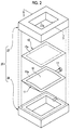
- a transfusion bag 10 as shown in Fig. 1 is constituted of, in rough classification, a bag main body (bonding target object) 11, a gas barrier function film (film) 12, and a bending resistant function film 13.
- the bag main body 11 is formed by, for example, sealing four sides in a state in which a flexible function film is folded, or in a state in which two flexible function films are made to overlap each other.
- a cylindrical mouth portion 17 which communicates with the inside of the liquid medicine chamber 16 is integrally provided in one end portion in the bag main body 11 through welding or the like. Although is not shown in the drawing, an opening hole of the mouth portion 17 is sealed by a mouth plug.
- the gas barrier function film 12 is bonded to one surface side (here, upper surface side in the drawing) of the bag main body 11 through adhering. More specifically, a film periphery portion 12a (for example, a region between a two-dot chain line and the outer circumference) of the gas barrier function film 12 is adhered to the one surface side of the main body periphery portion 11 a of the bag main body 11 so as to surround the liquid medicine chamber 16.
- This gas barrier function film 12 has a film main body 18 which includes a base material film layer 18a and a sealing function layer (layer with low toughness) 18b constituted of a single layer or multiple layers; and an adhesive layer 19 (refer to Fig. 3 ) which can be adhered to the bag main body 11.
- a reference numeral A2 in the drawing displays an enlarged dotted-line display portion A1 of the gas barrier function film 12.
- the sealing function layer 18b is, for example, a deposition layer of an inorganic oxide formed on the base material film layer 18a, and has gas barrier properties with respect to gas such as oxygen and moisture barrier properties with respect to moisture or the like.
- the sealing function layer has toughness lower than that of the resin film of the bag main body 11. That is, the sealing function layer 18b is formed of a brittle material. For this reason, brittle destruction is more easily caused in the sealing function layer 18b than in the bag main body 11.
- the adhesive layer 19 is adhered to an object to be adhered (here, bag main body 11) by being cooled and solidified or being thermally hardened as it is after being melted at a certain temperature or above.
- the type and structure of the gas barrier function film 12 are not particularly limited, and any well-known film having gas barrier properties can be used.
- the bending resistant function film 13 is bonded to the other surface side (here, lower surface side in the drawing) of the bag main body 11 through adhering. More specifically, a film periphery portion 13a (for example, a region between a two-dot chain line and the outer circumference) of the bending resistant function film 13 is adhered to the main body periphery portion 11a on the other surface side of the bag main body 11 so as to surround the liquid medicine chamber 16.
- the bending resistant function film 13 has a film main body 20 (refer to Fig. 8 ) including a base material film layer (not shown in the drawing), an aluminum layer (not shown in the drawing), and the like; and an adhesive layer 21 (refer to Fig.
- This bending resistant function film 13 has gas barrier properties and moisture barrier properties, and is more excellent in bending resistance than the gas barrier function film 12.
- the adhesive layer 21 is basically the same as the above-described adhesive layer 19.
- the type and structure of the bending resistant function film 13 are not particularly limited, and various films which have gas barrier properties and are excellent in bending resistance can be used.
- the gas barrier function film 12 is bonded to one surface side of the bag main body 11 through adhering using a set of pressurization molds (also called metal molds) 25 constituting the bonding device of the present invention.
- the gas barrier function film 12 is bonded to the bag main body 11 after being filled with the transfusion 15, but the gas barrier function film 12 may be bonded to the bag main body 11 before being filled with the transfusion 15.
- a set of pressurization molds 25 bonds the gas barrier function film 12 to the bag main body 11 by sandwiching the bag main body 11 and the gas barrier function film 12 to be pressed.
- This set of pressurization molds 25 is constituted of a first pressurization mold 27 formed of metal and a second pressurization mold 28 formed of flexible or hard rubber.
- a heating unit 29 such as a heater which heats the first pressurization mold 27 is incorporated in the first pressurization mold 27.
- the heating unit 29 may be provided in the second pressurization mold 28 or both in the first pressurization mold 27 and the second pressurization mold 28.
- the first pressurization mold 27 and the second pressurization mold 28 respectively have a first pressurization surface 27a and a second pressurization surface 28a which have a frame shape (that is, a shape corresponding to a four-side sealed portion surrounding the liquid medicine chamber 16 of the bag main body 11) and face each other.
- the first pressurization surface 27a presses the gas barrier function film 12.
- the second pressurization surface 28a presses the bag main body 11.
- a rectangular first opening hole (also called a cavity) 27b surrounded by the first pressurization surface 27a is opened in the first pressurization surface 27a and a rectangular second opening hole 28b surrounded by the second pressurization surface 28a is opened in the second pressurization surface 28a.
- the first and second opening holes 27b and 28b respectively correspond to opening holes of the present invention.
- the first edge 30 on the first opening hole 27b side of the first pressurization surface 27a is formed so as to be positioned further inside the first opening hole 27b and the second opening hole 28b (hereinafter, called inside of the opening) than the second edge 31 on the second opening hole 28b side of the second pressurization surface 28a.
- the outer shapes of the first pressurization surface 27a and the second pressurization surface 28a are formed to have the same size as each other.
- the width W1 of one side of the first pressurization surface 27a is formed to 5 mm and the width W2 of one side of the second pressurization surface 28a is formed to 4 mm. Accordingly, the first pressurization surface 27a is formed to be wider than the second pressurization surface 28a by 1 mm toward the inside of the opening, and therefore, the first edge 30 is positioned further inside the opening than the second edge 31 by 1 mm.
- the bag main body 11 and the gas barrier function film 12 are set in a state in which the bag main body and the gas barrier function film overlap each other between the first pressurization mold 27 and the second pressurization mold 28.
- the gas barrier function film 12 is set on a surface side facing the first pressurization mold 27 and the bag main body 11 is set on a surface side facing the second pressurization mold 28.
- the gas barrier function film 12 is overlapped at a predetermined bonding position on one surface side of the bag main body 11 such that the adhesive layer 19 comes into contact with the main body periphery portion 11a of the bag main body 11.
- the adhesive layer 19 may be provided in a frame shape on the other surface side of a pressing target portion which is sandwiched between the first pressurization surface 27a and the second pressurization surface 28a of the film periphery portion 12a (hereinafter, also simply called a pressing target portion) to be pressed.
- the gas barrier function film 12 and the bag main body 11 are sandwiched by the first pressurization mold 27 and the second pressurization mold 28 which have been heated by the heating unit 29, to be pressed. Accordingly, the film periphery portion 12a is pressed by the first pressurization surface 27a toward the main body periphery portion 11a, and the main body periphery portion 11a is pressed by the second pressurization surface 28a toward the film periphery portion 12a. Then, the adhesive layer 19 is melt through heating using the first pressurization mold 27, and the pressing target portion of the film periphery portion 12a (portion formed on the adhesive layer 19) is bonded to the main body periphery portion 11 a through adhering.
- the pressing using the first pressurization mold 27 and the second pressurization mold 28 is released after the lapse of a predetermined time for pressing.
- the bonding of the gas barrier function film 12 to one surface side of the bag main body 11 has been completed. Accordingly, a space for preventing oxygen or the like from entering the bag main body 11 is formed on the one surface side of the bag main body 11.
- the first edge 30 is positioned further inside the opening than the second edge 31. Therefore, destruction of the sealing function layer 18b of the gas barrier function film 12 caused by the pressing using the first pressurization mold 27 is prevented.
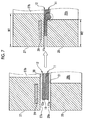
- the first edge 30 is positioned further inside the opening than the second edge 31 (W1 ⁇ W2) as shown in Fig. 7 .
- a force in a direction in which the main body periphery portion 11 a in the vicinity of the first edge 30 is deformed to the back side (downward in the drawing) of the second opening hole 28b is concentrated due to the pressing using the first pressurization mold 27 and the second pressurization mold 28 contrary to Comparative Example shown in Fig. 5 .
- the main body periphery portion 11 a in the vicinity of the first edge 30 is deformed (refer to a portion surrounded by a dotted line in the drawing) so as to swell toward the back side of the second opening hole 28b.
- steep bending and deformation which result in destruction of the sealing function layer 18b caused by the first edge 30 is prevented from being caused in the gas barrier function film 12, or a mark caused by the first edge 30 is prevented from remaining in the gas barrier function film 12. Therefore, the destruction of the sealing function layer 18b is prevented.
- the first pressurization surface 27a is formed to be wider than the second pressurization surface 28a by 1 mm toward the inside of the opening. That is, the position of the first edge 30 is determined to be at a position further on the inside of the opening than that of the second edge 31 by 1 mm.
- the position of the first edge 30 can be changed. Specifically, deformation of the gas barrier function film 12 caused by the first edge 30 or remaining of a mark in the gas barrier function film 12 caused by the first edge is prevented by making the position of the first edge 30 be further on the inside of the opening than that of the second edge 31 by 0.5 mm or more.
- bonding of the bending resistant function film 13 to the bag main body 11 is started after forming a bonded body 35 which is obtained by bonding the film periphery portion 12a of the gas barrier function film 12 to one surface side of the bag main body 11.
- a set of pressurization molds 25S which is constituted of the first pressurization mold 27S and the second pressurization mold 28S is used.
- the first pressurization mold 27S is a mold in which the above-described first pressurization mold 27 is set as a lower mold.
- the first pressurization mold 27S is formed of rubber and does not have the heating unit 29.
- the second pressurization mold 28S is a mold in which the above-described second pressurization mold 28 is set as an upper mold.
- the second pressurization mold 28S is formed of metal and has the heating unit 29.
- the width W1 of one side of the first pressurization surface 27a is formed to 4 mm and the width W2 of one side of the second pressurization surface 28a is formed to 3 mm. Accordingly, the first pressurization surface 27a is formed to be wider than the second pressurization surface 28a by 1 mm toward the inside of the opening, and therefore, the first edge 30 is positioned further inside the opening than the second edge 31 by 1 mm.
- the bonded body 35 and the bending resistant function film 13 are set in a state of overlapping each other, between the first pressurization mold 27S and the second pressurization mold 28S.
- the bonded body 35 is set on the surface side facing the first pressurization mold 27S and the gas barrier function film 12 is set so as to face the first pressurization mold 27S.
- the bending resistant function film 13 is set on the surface side facing the second pressurization mold 28S.
- the bending resistant function film 13 is overlapped at a predetermined bonding position on the other surface side of the bag main body 11 such that the adhesive layer 21 comes into contact with the main body periphery portion 11 a of the bag main body 11.
- the adhesive layer 21 is provided in a frame shape on the other surface side of a pressing target portion of the film periphery portion 13a.
- the bonded body 35 and the bending resistant function film 13 are sandwiched by the first pressurization mold 27S and the second pressurization mold 28S which has been heated by the heating unit 29, to be pressed. Accordingly, the first pressurization surface 27a presses the main body periphery portion 11 a to the film periphery portion 13a. In addition, the second pressurization surface 28a presses the film periphery portion 13a to the main body periphery portion 11a. Then, the adhesive layer 21 is melt through heating using the second pressurization mold 28S, and the pressing target portion of the film periphery portion 13a is bonded to the other surface side of the main body periphery portion 11a through adhering. Accordingly, a space for preventing oxygen or the like from entering the bag main body 11 is formed on the other surface side of the bag main body 11.
- the gas barrier function film 12 which includes the sealing function layer 18b having toughness lower than that of the bending resistant function film 13 is pressed by the first pressurization surface 27a.
- the first edge 30 of the first pressurization surface 27a is positioned further inside the opening than the second edge 31 of the second pressurization surface 28a. Therefore, destruction of the sealing function layer 18b of the gas barrier function film 12 is prevented similarly at the time of bonding of the above-described gas barrier function film 12.
- the pressing using the first pressurization mold 27S and the second pressurization mold 28S is released after the lapse of a predetermined time for pressing.
- the transfusion bag 10 is formed after the completion of the bonding of the bending resistant function film 13 to the other surface side of the bag main body 11.
- the position of the first edge 30 of the first pressurization surface 27a which presses the gas barrier function film 12 including the sealing function layer 18b with low toughness is set to be positioned further inside the opening than the position of the second edge 31 of the second pressurization surface 28a (W1 > W2). Accordingly, deformation of the gas barrier function film 12 caused by the first edge 30 during bonding (during pressing) or remaining of a mark of the first edge 30 in the gas barrier function film 12 caused by the first edge is prevented. As a result, the destruction the sealing function layer 18b of the gas barrier function film 12 is prevented, and therefore, it is possible to seal one surface side of the bag main body 11 using the gas barrier function film 12 while maintaining the sealing function of the sealing function layer 18b to its maximum.
- the first edge 30 is formed by a corner portion formed by the first pressurization surface 27a and the first opening hole 27b.
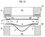
- a curved first edge 30a may be formed by, for example, chamfering the first edge 30 to R1.0 (by chamfering the first edge so as to have an arc with a radius of 1.0 mm).
- the force of the chamfered first edge 30a to deform the gas barrier function film 12 (film periphery portion 12a) becomes smaller than that of the first edge 30. Therefore, it is possible to more reliably prevent the destruction of the sealing function layer of the gas barrier function film 12.
- the chamfering of the first edge 30 is not limited R chamfering, and C chamfering (chamfering at a chamfering angle of 45°) may be performed.
- the second edge 31 may be chamfered without being limited to the first edge 30.
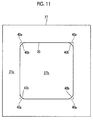
- the first opening hole 27b is formed in a rectangular shape. Therefore, a bent portion 40a (represented by a two-dot chain line) corresponding to four corner portions of the first opening hole 27b is included in the edge line of the first edge 30 which forms a contour of this first opening hole 27b as shown in Fig. 11 . Accordingly, the edge line of the first edge 30 may be formed to have a smoothly connected shape. Specifically, here, the bent portion 40a of the edge line of the first edge 30 is formed as a curved unit 40b having a curved shape.
- the force of the first edge 30, at a position corresponding to the four corner portions (corner portions) of the first opening hole 27b, to deform the gas barrier function film 12 (film periphery portion 12a) becomes small. Therefore, it is possible to more reliably prevent the destruction of the sealing function layer 18b of the gas barrier function film 12.
- the edge line of the first edge 30 is formed to have a smoothly connected shape
- the edge line of the second edge 31 which forms a contour of the second opening hole 28b is also formed to have a smoothly connected shape (not shown in the drawing).
- the embodiment shown in Fig. 10 may be combined with the embodiment shown in Fig. 11 .
- the gas barrier function film 12 (the same applies to the bending resistant function film 13) is bonded to the bag main body 11 through adhering.
- the gas barrier function film 12 may be bonded to the bag main body 11 through welding.
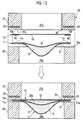
- a welding layer 42 is provided in the gas barrier function film 12 instead of the adhesive layer 19.
- the welding method it is possible to use a well-known welding method such as thermal welding, high frequency welding, ultrasonic wave welding, or the like.
- a set of pressurization molds 25 for heat sealing is used.
- the first pressurization surface 27a is heated to a high temperature using the heating unit 29 while sandwiching the gas barrier function film 12 and the bag main body 11 between the first pressurization mold 27 and the second pressurization mold 28 to be pressed. Accordingly, the film periphery portion 12a and the main body periphery portion 11a are welded due to the melting of the welding layer 42.
- the position of the first edge 30 of the first pressurization mold 27 is positioned further inside the opening than the position of the second edge 31 of the second pressurization mold 28. For this reason, destruction of the sealing function layer 18b of the gas barrier function film 12 caused by the pressing using the first pressurization mold 27 and the second pressurization mold 28 is prevented.
- the bending resistant function film 13 can also be bonded to the bag main body 11 through welding.
- the first pressurization surface 27a does not have releasability with respect to the gas barrier function film 12.
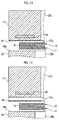
- a surface treatment layer 45 which has releasability with respect to the gas barrier function film 12 may be formed by performing surface treatment on the first pressurization surface 27a. Accordingly, the gas barrier function film 12 can be easily peeled from the first pressurization surface 27a after the pressing of the gas barrier function film 12 performed by the first pressurization surface 27a.
- baking may be performed as a type of the surface treatment which is performed on the first pressurization surface 27a.
- a tape 46 may be, for example, stuck to the first pressurization surface 27a as shown in Fig. 14 , instead of performing surface treatment on the first pressurization surface 27a. Accordingly, it is possible to secure the releasability of the first pressurization surface 27a with respect to the gas barrier function film 12.
- a sheet may be disposed between the first pressurization surface 27a and the gas barrier function film 12 and the gas barrier function film 12 may be pressed by the first pressurization surface 27a in a state in which this sheet is sandwiched therebetween. Even in this case, it is possible to secure the releasability of the first pressurization surface 27a with respect to the gas barrier function film 12.
- the bending resistant function film 13 is bonded to the other surface side of the bag main body 11.
- the order of the bonding may be reversed. That is, as shown in Fig. 15 , after first bonding the bending resistant function film 13 to the other surface side of the bag main body 11, the gas barrier function film 12 may be bonded to one surface side of the bag main body 11.
- the bonding is performed such that the gas barrier function film 12 is prevented from more swelling than the bending resistant function film 13. That is, the bending resistant function film 13 is set to be in a state of more swelling than the gas barrier function film 12. Accordingly, when bonding the gas barrier function film 12 to the bag main body 11, it is possible to secure a volume of the content (transfusion 15) by making the bending resistant function film 13 to swell. As a result, it is possible to bond the gas barrier function film 12 to the bag main body 11 without destruction of the sealing function layer 18b.
- the first pressurization mold 27 is formed of metal and the second pressurization mold 28 is formed of a rubber material.
- at least one of the first pressurization mold 27 and the second pressurization mold 28 may be formed of a metal material, a rubber material, a resin material, a ceramic material, wood, or the like.
- At least one of the first pressurization mold 27S and the second pressurization mold 28S may also be formed of a metal material, a rubber material, a resin material, a ceramic material, wood, or the like.
- the gas barrier function film 12 has been described as a film of the present invention.
- a resin film having various functions such as steam barrier properties in addition to the gas barrier properties may be used.
- various resin films having higher bending properties than the gas barrier function film 12 may be used as the bending resistant function film 13.
- the first pressurization surface 27a and the second pressurization surface 28a are formed in a rectangular shape, but the shapes thereof may be appropriately changed to the shape of the liquid medicine chamber 16.
- first pressurization surface 27a and the second pressurization surface 28a are sealed by four sides of each of the bag main body 11 and the gas barrier function film 12 (bending resistant function film 13).
- first pressurization surface 27a and the second pressurization surface 28a may be formed in a shape corresponding to the two-side sealing, three-side sealing, or the like.
- the gas barrier function film 12 or the bending resistant function film 13 is bonded to the bag main body 11.
- the gas barrier function film 12 or the like may be first bonded to a flexible resin film before being formed on the bag main body 11.
- the case of bonding the gas barrier function film 12 to the bag main body 11 of the transfusion bag 10 has been described as an example.
- the present invention to the bonding method and the bonding device for bonding various films including a layer with low toughness to various bonding target objects in addition to the transfusion bag 10 of a packaging container or the like containing various kinds of liquid medicines, powder medicines, food, powder (sugar or the like) which is weak to humidity, and an inspection chip which detects specific gas.
Landscapes
- Engineering & Computer Science (AREA)
- Mechanical Engineering (AREA)
- Bag Frames (AREA)
- Medical Preparation Storing Or Oral Administration Devices (AREA)
- Auxiliary Devices For And Details Of Packaging Control (AREA)
- Making Paper Articles (AREA)
Abstract
Description
- The present invention relates to a bonding method and device for bonding a film to an object to be welded.
- In general, a liquid medicine, a powder medicine, food, powder (sugar or the like) which is weak to humidity, an inspection chip which detects specific gas, and the like are packaged in a packaging container. As a kind of such a packaging container, for example, a transfusion bag filled with a transfusion containing sugar, an electrolyte, amino acids, vitamins, or the like is well known. A transfusion bag is formed of a resin film (plastic film) or the like in view of good handling properties, being lightweight, reduction in volume of waste, or the like.
- The resin film used as a material of the transfusion bag has low gas barrier properties since an additive, which improves gas barrier properties, is used in an additive-free manner in order to prevent such an additive from being injected into a human body after being eluted in the transfusion. Here, it is easy for liquid medicines, such as sugar, amino acids, or an electrolyte, with which the transfusion bag is filled to significantly deteriorate due to entering of oxygen. Therefore, if the transfusion bag is left to stand in the air, the liquid medicine deteriorates due to oxygen in the air transmitted through the transfusion bag.
- In a transfusion bag disclosed in
JP1999-56970A JP-H11-56970A - In a transfusion bag disclosed in
JP1999-348171A JP-H11-348171A JP1999-56970A JP-H11-56970A - In
JP2004-231199A - However, in
JP1999-56970A JP-H11-56970A JP1999-348171A JP-H11-348171A - In the transfusion bag disclosed in
JP2004-231199A - An object of the present invention is to provide a bonding method and device which can prevent destruction of a layer with low toughness when bonding a film containing the layer with low toughness to a bonding target object.
- A bonding method for achieving an object of the present invention, is a bonding method for bonding a pressing target portion of a film which is pressed by a set of pressurization molds to a bonding target object by disposing the bonding target object and the film including a layer having lower toughness than the bonding target object between the set of pressurization molds, which have pressurization surfaces disposed so as to face each other and in which opening holes are formed in the pressurization surfaces, and by sandwiching the bonding target object and the film with the set of pressurization molds to be pressed, the method including: bonding the pressing target portion to the bonding target object using the set of pressurization molds having a configuration in which a first edge on the opening hole side of the pressurization surface of a first pressurization mold, out of the set of pressurization molds, which faces the film is positioned further inside the opening hole than a second edge on the opening hole side of the pressurization surface of a second pressurization mold which faces the bonding target object.
- According to the present invention, deformation of the film caused by the first edge or remaining of a mark of the first edge in the film is prevented when bonding the film to the bonding target object using the set of pressurization molds.
- It is preferable that the pressing of the film is performed using the first pressurization mold in which the first edge is chamfered. Accordingly, it is possible to reliably prevent the destruction of the layer, which has low toughness, of the film.
- It is preferable that an adhesive layer is formed on a surface side of the pressing target portion facing the bonding target object, and the set of pressurization molds bonds the pressing target portion to the bonding target object through the adhesive layer. It is possible to bond the film to the bonding target object through adhering.
- It is preferable that the set of pressurization molds bonds the pressing target portion to the bonding target object through welding. It is possible to bond the film to the bonding target object through welding.
- It is preferable that the pressing target portion of the film is bonded to one surface side of the bonding target object, and then, a pressing target portion of a bending resistant function film, which is positioned on the other surface side of the bonding target object and has higher bending resistance than the film, is bonded to the bonding target object by disposing the bonding target object and the bending resistant function film between the set of pressurization molds, and sandwiching the bonding target object and the bending resistant function film with the set of pressurization molds to press the bending resistant function film on the one surface side of the bonding target object using the first pressurization mold and to press the bending resistant function film using the second pressurization mold. When bonding the bending resistant function film to the other side of the bonding target object, destruction of a layer, which has low toughness, of the film on the one surface side of the bonding target object is prevented.
- It is preferable that the pressing target portion of the film is bonded to one surface side of the bonding target object using the set of pressurization molds in a state in which the film is suppressed not to swell more than a bending resistant function film having higher bending resistance than the film, after bonding the bending resistant function film to the other surface side of the bonding target object. In a case where bonding target objects, to which the film is bonded, are various containers, the bending resistant function film is bonded to the bonding target objects without destruction of the layer, which has low toughness, of the film by securing a volume of the content of the containers by causing the bending resistant function film to swell.
- It is preferable that at least one of the first pressurization mold and the second pressurization mold is formed of any of metal, a rubber material, a resin material, a ceramic material, and wood.
- It is preferable that at least the first pressurization mold out of the first pressurization mold and the second pressurization mold performs pressing of the film using a pressurization surface having releasability with respect to the film. Accordingly, it is possible to easily release the film from the pressurization surface after the pressing of the film using the first pressurization mold (also including the second pressurization mold in a case where the pressurization surface of the second pressurization mold has releasability).
- It is preferable that the pressurization surface of at least the first pressurization mold out of the first pressurization mold and the second pressurization mold presses the film through tape which is stuck to the pressurization surface or a sheet provided between the pressurization surface and the film. Accordingly, it is possible to easily release the film from the pressurization surface after the pressing of the film using the first pressurization mold (the second pressurization mold can also be used).
- It is preferable that an edge line of the first edge which forms a contour of the opening hole of the first pressurization mold is formed to have a smoothly connected shape and an edge line of the second edge which forms a contour of the opening hole of the second pressurization mold is formed to have a smoothly connected shape. Accordingly, it is possible to reliably prevent the destruction of the layer, which has low toughness, of the film.
- It is preferable that the bonding target object and the film are sandwiched with the set of pressurization molds, which have the pressurization surfaces formed in a frame shape and the opening holes which are surrounded by the pressurization surfaces, to be pressed. Accordingly, it is possible to seal one surface of the bonding target object using the film.
- A bonding device for achieving an object of the present invention is a bonding device which bonds a pressing target portion of a film which is pressed by a set of pressurization molds by disposing a bonding target object and a film including a layer having lower toughness than the bonding target object between the set of pressurization molds, which have pressurization surfaces disposed so as to face each other and in which opening holes are formed in the pressurization surfaces, and by sandwiching the bonding target object and the film with the set of pressurization molds to be pressed, in which a first edge on the opening hole side of the pressurization surface of a first pressurization mold, out of the set of pressurization molds, which faces the film is positioned further inside the opening hole than a second edge on the opening hole side of the pressurization surface of a second pressurization mold which faces the bonding target object.
- The bonding method and device of the present invention can prevent destruction of a layer with low toughness when bonding a film including the layer with low toughness to a bonding target object.
-
-
Fig. 1 is an exploded perspective view of a transfusion bag. -
Fig. 2 is a perspective view of a first pressurization mold and a second pressurization mold (a set of pressurization molds). -
Fig. 3 is an explanatory view for illustrating a state a gas barrier function film and a bag main body is sandwiched with the first pressurization mold and the second pressurization mold to be pressed. -
Fig. 4 is an explanatory view for illustrating a state in which the gas barrier function film and the bag main body are sandwiched with the first pressurization mold and the second pressurization mold to be pressed. -
Fig. 5 is an explanatory view for illustrating Comparative Example in which a second edge is positioned inside an opening hole than a first edge. -
Fig. 6 is an explanatory view for illustrating Comparative Example in which a first edge and a second edge are at the same position as each other. -
Fig. 7 is an explanatory view for illustrating the reason why destruction of a sealing function layer of a gas barrier function film is prevented. -
Fig. 8 is an explanatory view for illustrating a state a bending resistant function film and a bag main body is sandwiched with a first pressurization mold and a second pressurization mold to be pressed. -
Fig. 9 is an explanatory view for illustrating a state in which the bending resistant function film and the bag main body is sandwiched with the first pressurization mold and the second pressurization mold to be pressed. -
Fig. 10 is an explanatory view for illustrating another embodiment in which the first edge is chamfered. -
Fig. 11 is an explanatory view for illustrating still another embodiment in which a bent portion of an edge line of the first embodiment is formed in a curved shape. -
Fig. 12 is an explanatory view for illustrating still another embodiment in which a gas barrier function film is bonded to a bag main body through welding. -
Fig. 13 is an explanatory view for illustrating still another embodiment in which a first pressurization surface has releasability with respect to a gas barrier function film due to surface treatment. -
Fig. 14 is an explanatory view for illustrating still another embodiment in which tape is pasted to a first pressurization surface. -
Fig. 15 is an explanatory view for illustrating still another embodiment in which bonding of a gas barrier function film to a bag main body is performed after bonding of a bending resistant function film to the bag main body. - A
transfusion bag 10 as shown inFig. 1 is constituted of, in rough classification, a bag main body (bonding target object) 11, a gas barrier function film (film) 12, and a bendingresistant function film 13. - The bag
main body 11 is formed by, for example, sealing four sides in a state in which a flexible function film is folded, or in a state in which two flexible function films are made to overlap each other. Aliquid medicine chamber 16, which is filled with a transfusion 15 (refer toFig. 3 ) and is sealed, is formed in the bagmain body 11 by sealing four sides of a mainbody periphery portion 11 a. In addition, acylindrical mouth portion 17 which communicates with the inside of theliquid medicine chamber 16 is integrally provided in one end portion in the bagmain body 11 through welding or the like. Although is not shown in the drawing, an opening hole of themouth portion 17 is sealed by a mouth plug. - The gas
barrier function film 12 is bonded to one surface side (here, upper surface side in the drawing) of the bagmain body 11 through adhering. More specifically, afilm periphery portion 12a (for example, a region between a two-dot chain line and the outer circumference) of the gasbarrier function film 12 is adhered to the one surface side of the mainbody periphery portion 11 a of the bagmain body 11 so as to surround theliquid medicine chamber 16. This gasbarrier function film 12 has a filmmain body 18 which includes a base material film layer 18a and a sealing function layer (layer with low toughness) 18b constituted of a single layer or multiple layers; and an adhesive layer 19 (refer toFig. 3 ) which can be adhered to the bagmain body 11. A reference numeral A2 in the drawing displays an enlarged dotted-line display portion A1 of the gasbarrier function film 12. - The sealing
function layer 18b is, for example, a deposition layer of an inorganic oxide formed on the base material film layer 18a, and has gas barrier properties with respect to gas such as oxygen and moisture barrier properties with respect to moisture or the like. However, the sealing function layer has toughness lower than that of the resin film of the bagmain body 11. That is, the sealingfunction layer 18b is formed of a brittle material. For this reason, brittle destruction is more easily caused in thesealing function layer 18b than in the bagmain body 11. In addition, theadhesive layer 19 is adhered to an object to be adhered (here, bag main body 11) by being cooled and solidified or being thermally hardened as it is after being melted at a certain temperature or above. - The type and structure of the gas
barrier function film 12 are not particularly limited, and any well-known film having gas barrier properties can be used. - The bending
resistant function film 13 is bonded to the other surface side (here, lower surface side in the drawing) of the bagmain body 11 through adhering. More specifically, afilm periphery portion 13a (for example, a region between a two-dot chain line and the outer circumference) of the bendingresistant function film 13 is adhered to the mainbody periphery portion 11a on the other surface side of the bagmain body 11 so as to surround theliquid medicine chamber 16. The bendingresistant function film 13 has a film main body 20 (refer toFig. 8 ) including a base material film layer (not shown in the drawing), an aluminum layer (not shown in the drawing), and the like; and an adhesive layer 21 (refer toFig. 8 ) which can be adhered to the bagmain body 11. This bendingresistant function film 13 has gas barrier properties and moisture barrier properties, and is more excellent in bending resistance than the gasbarrier function film 12. In addition, theadhesive layer 21 is basically the same as the above-describedadhesive layer 19. - The type and structure of the bending
resistant function film 13 are not particularly limited, and various films which have gas barrier properties and are excellent in bending resistance can be used. - As shown in
Figs. 2 and3 , the gasbarrier function film 12 is bonded to one surface side of the bagmain body 11 through adhering using a set of pressurization molds (also called metal molds) 25 constituting the bonding device of the present invention. In the present embodiment, the gasbarrier function film 12 is bonded to the bagmain body 11 after being filled with thetransfusion 15, but the gasbarrier function film 12 may be bonded to the bagmain body 11 before being filled with thetransfusion 15. - A set of
pressurization molds 25 bonds the gasbarrier function film 12 to the bagmain body 11 by sandwiching the bagmain body 11 and the gasbarrier function film 12 to be pressed. This set ofpressurization molds 25 is constituted of afirst pressurization mold 27 formed of metal and asecond pressurization mold 28 formed of flexible or hard rubber. In addition, aheating unit 29 such as a heater which heats thefirst pressurization mold 27 is incorporated in thefirst pressurization mold 27. Theheating unit 29 may be provided in thesecond pressurization mold 28 or both in thefirst pressurization mold 27 and thesecond pressurization mold 28. - The
first pressurization mold 27 and thesecond pressurization mold 28 respectively have afirst pressurization surface 27a and asecond pressurization surface 28a which have a frame shape (that is, a shape corresponding to a four-side sealed portion surrounding theliquid medicine chamber 16 of the bag main body 11) and face each other. Thefirst pressurization surface 27a presses the gasbarrier function film 12. Thesecond pressurization surface 28a presses the bagmain body 11. - A rectangular first opening hole (also called a cavity) 27b surrounded by the
first pressurization surface 27a is opened in thefirst pressurization surface 27a and a rectangularsecond opening hole 28b surrounded by thesecond pressurization surface 28a is opened in thesecond pressurization surface 28a. The first and second opening holes 27b and 28b respectively correspond to opening holes of the present invention. Moreover, thefirst edge 30 on thefirst opening hole 27b side of thefirst pressurization surface 27a is formed so as to be positioned further inside thefirst opening hole 27b and thesecond opening hole 28b (hereinafter, called inside of the opening) than thesecond edge 31 on thesecond opening hole 28b side of thesecond pressurization surface 28a. - Specifically, the outer shapes of the
first pressurization surface 27a and thesecond pressurization surface 28a are formed to have the same size as each other. In addition, the width W1 of one side of thefirst pressurization surface 27a is formed to 5 mm and the width W2 of one side of thesecond pressurization surface 28a is formed to 4 mm. Accordingly, thefirst pressurization surface 27a is formed to be wider than thesecond pressurization surface 28a by 1 mm toward the inside of the opening, and therefore, thefirst edge 30 is positioned further inside the opening than thesecond edge 31 by 1 mm. - The bag
main body 11 and the gasbarrier function film 12 are set in a state in which the bag main body and the gas barrier function film overlap each other between thefirst pressurization mold 27 and thesecond pressurization mold 28. At this time, the gasbarrier function film 12 is set on a surface side facing thefirst pressurization mold 27 and the bagmain body 11 is set on a surface side facing thesecond pressurization mold 28. In addition, the gasbarrier function film 12 is overlapped at a predetermined bonding position on one surface side of the bagmain body 11 such that theadhesive layer 19 comes into contact with the mainbody periphery portion 11a of the bagmain body 11. Theadhesive layer 19 may be provided in a frame shape on the other surface side of a pressing target portion which is sandwiched between thefirst pressurization surface 27a and thesecond pressurization surface 28a of thefilm periphery portion 12a (hereinafter, also simply called a pressing target portion) to be pressed. - As shown in
Fig. 4 , the gasbarrier function film 12 and the bagmain body 11 are sandwiched by thefirst pressurization mold 27 and thesecond pressurization mold 28 which have been heated by theheating unit 29, to be pressed. Accordingly, thefilm periphery portion 12a is pressed by thefirst pressurization surface 27a toward the mainbody periphery portion 11a, and the mainbody periphery portion 11a is pressed by thesecond pressurization surface 28a toward thefilm periphery portion 12a. Then, theadhesive layer 19 is melt through heating using thefirst pressurization mold 27, and the pressing target portion of thefilm periphery portion 12a (portion formed on the adhesive layer 19) is bonded to the mainbody periphery portion 11 a through adhering. - The pressing using the
first pressurization mold 27 and thesecond pressurization mold 28 is released after the lapse of a predetermined time for pressing. Here, the bonding of the gasbarrier function film 12 to one surface side of the bagmain body 11 has been completed. Accordingly, a space for preventing oxygen or the like from entering the bagmain body 11 is formed on the one surface side of the bagmain body 11. At this time, in the present embodiment, thefirst edge 30 is positioned further inside the opening than thesecond edge 31. Therefore, destruction of thesealing function layer 18b of the gasbarrier function film 12 caused by the pressing using thefirst pressurization mold 27 is prevented. - In contrast, in
Fig. 5 showing Comparative Example, in a case where thesecond edge 31 is positioned further inside the opening than the first edge 30 (W1 < W2), a force in a direction in which thefilm periphery portion 12a in the vicinity of thefirst edge 30 is deformed to the back side (upward in the drawing) of thefirst opening hole 27b is concentrated due to the pressing performed using thefirst pressurization mold 27 and thesecond pressurization mold 28. Accordingly, thefilm periphery portion 12a in the vicinity of thefirst edge 30 is steeply bent and deformed (refer to a portion surrounded by a dotted line in the drawing) so as to swell toward the back side of thefirst opening hole 27b. As a result, destruction is caused in thesealing function layer 18b of the gasbarrier function film 12. - In addition, in
Fig. 6 shown in Comparative Example, even in a case where thefirst edge 30 and thesecond edge 31 are at the same position as each other (W1 = W2), if a slight deviation of the contact position is caused during the pressing using thefirst pressurization mold 27 and thesecond pressurization mold 28, there is a possibility that thesecond edge 31 may be positioned further inside the opening than thefirst edge 30. In addition, even in a case where thefirst edge 30 and thesecond edge 31 are designed to be at the same position as each other, there is a possibility that thesecond edge 31 may be positioned further inside the opening than thefirst edge 30 due to the difference in processing accuracy of thefirst pressurization mold 27 and thesecond pressurization mold 28. For this reason, in a case where thesecond edge 31 is positioned further inside the opening than thefirst edge 30 due to the deviation of the contact position or the difference in the processing accuracy, deformation and destruction of thesealing function layer 18b (the portion surrounded by a dotted line in the drawing) of the gasbarrier function film 12 are caused as shown inFig. 5 . - With respect to such Comparative Example, in the present invention, the
first edge 30 is positioned further inside the opening than the second edge 31 (W1 < W2) as shown inFig. 7 . For this reason, a force in a direction in which the mainbody periphery portion 11 a in the vicinity of thefirst edge 30 is deformed to the back side (downward in the drawing) of thesecond opening hole 28b is concentrated due to the pressing using thefirst pressurization mold 27 and thesecond pressurization mold 28 contrary to Comparative Example shown inFig. 5 . Accordingly, the mainbody periphery portion 11 a in the vicinity of thefirst edge 30 is deformed (refer to a portion surrounded by a dotted line in the drawing) so as to swell toward the back side of thesecond opening hole 28b. As a result, steep bending and deformation which result in destruction of thesealing function layer 18b caused by thefirst edge 30 is prevented from being caused in the gasbarrier function film 12, or a mark caused by thefirst edge 30 is prevented from remaining in the gasbarrier function film 12. Therefore, the destruction of thesealing function layer 18b is prevented. - Here, in the present embodiment, the
first pressurization surface 27a is formed to be wider than thesecond pressurization surface 28a by 1 mm toward the inside of the opening. That is, the position of thefirst edge 30 is determined to be at a position further on the inside of the opening than that of thesecond edge 31 by 1 mm. However, the position of thefirst edge 30 can be changed. Specifically, deformation of the gasbarrier function film 12 caused by thefirst edge 30 or remaining of a mark in the gasbarrier function film 12 caused by the first edge is prevented by making the position of thefirst edge 30 be further on the inside of the opening than that of thesecond edge 31 by 0.5 mm or more. - As shown in
Fig. 8 , bonding of the bendingresistant function film 13 to the bagmain body 11 is started after forming a bondedbody 35 which is obtained by bonding thefilm periphery portion 12a of the gasbarrier function film 12 to one surface side of the bagmain body 11. During the bonding of this bendingresistant function film 13, a set ofpressurization molds 25S which is constituted of thefirst pressurization mold 27S and thesecond pressurization mold 28S is used. - The
first pressurization mold 27S is a mold in which the above-describedfirst pressurization mold 27 is set as a lower mold. Thefirst pressurization mold 27S is formed of rubber and does not have theheating unit 29. In contrast, thesecond pressurization mold 28S is a mold in which the above-describedsecond pressurization mold 28 is set as an upper mold. Thesecond pressurization mold 28S is formed of metal and has theheating unit 29. In addition, the width W1 of one side of thefirst pressurization surface 27a is formed to 4 mm and the width W2 of one side of thesecond pressurization surface 28a is formed to 3 mm. Accordingly, thefirst pressurization surface 27a is formed to be wider than thesecond pressurization surface 28a by 1 mm toward the inside of the opening, and therefore, thefirst edge 30 is positioned further inside the opening than thesecond edge 31 by 1 mm. - First, the bonded
body 35 and the bendingresistant function film 13 are set in a state of overlapping each other, between thefirst pressurization mold 27S and thesecond pressurization mold 28S. At this time, the bondedbody 35 is set on the surface side facing thefirst pressurization mold 27S and the gasbarrier function film 12 is set so as to face thefirst pressurization mold 27S. The bendingresistant function film 13 is set on the surface side facing thesecond pressurization mold 28S. In addition, the bendingresistant function film 13 is overlapped at a predetermined bonding position on the other surface side of the bagmain body 11 such that theadhesive layer 21 comes into contact with the mainbody periphery portion 11 a of the bagmain body 11. Theadhesive layer 21 is provided in a frame shape on the other surface side of a pressing target portion of thefilm periphery portion 13a. - As shown in
Fig. 9 , the bondedbody 35 and the bendingresistant function film 13 are sandwiched by thefirst pressurization mold 27S and thesecond pressurization mold 28S which has been heated by theheating unit 29, to be pressed. Accordingly, thefirst pressurization surface 27a presses the mainbody periphery portion 11 a to thefilm periphery portion 13a. In addition, thesecond pressurization surface 28a presses thefilm periphery portion 13a to the mainbody periphery portion 11a. Then, theadhesive layer 21 is melt through heating using thesecond pressurization mold 28S, and the pressing target portion of thefilm periphery portion 13a is bonded to the other surface side of the mainbody periphery portion 11a through adhering. Accordingly, a space for preventing oxygen or the like from entering the bagmain body 11 is formed on the other surface side of the bagmain body 11. - Even in such bonding of the bending resistant function film 13 (
film periphery portion 13a), the gasbarrier function film 12 which includes thesealing function layer 18b having toughness lower than that of the bendingresistant function film 13 is pressed by thefirst pressurization surface 27a. Thefirst edge 30 of thefirst pressurization surface 27a is positioned further inside the opening than thesecond edge 31 of thesecond pressurization surface 28a. Therefore, destruction of thesealing function layer 18b of the gasbarrier function film 12 is prevented similarly at the time of bonding of the above-described gasbarrier function film 12. - The pressing using the
first pressurization mold 27S and thesecond pressurization mold 28S is released after the lapse of a predetermined time for pressing. Here, thetransfusion bag 10 is formed after the completion of the bonding of the bendingresistant function film 13 to the other surface side of the bagmain body 11. - In the present invention as described above, the position of the
first edge 30 of thefirst pressurization surface 27a which presses the gasbarrier function film 12 including thesealing function layer 18b with low toughness is set to be positioned further inside the opening than the position of thesecond edge 31 of thesecond pressurization surface 28a (W1 > W2). Accordingly, deformation of the gasbarrier function film 12 caused by thefirst edge 30 during bonding (during pressing) or remaining of a mark of thefirst edge 30 in the gasbarrier function film 12 caused by the first edge is prevented. As a result, the destruction thesealing function layer 18b of the gasbarrier function film 12 is prevented, and therefore, it is possible to seal one surface side of the bagmain body 11 using the gasbarrier function film 12 while maintaining the sealing function of thesealing function layer 18b to its maximum. - In the above-described embodiment, the
first edge 30 is formed by a corner portion formed by thefirst pressurization surface 27a and thefirst opening hole 27b. However, as shown inFig. 10 , a curvedfirst edge 30a may be formed by, for example, chamfering thefirst edge 30 to R1.0 (by chamfering the first edge so as to have an arc with a radius of 1.0 mm). The force of the chamferedfirst edge 30a to deform the gas barrier function film 12 (film periphery portion 12a) becomes smaller than that of thefirst edge 30. Therefore, it is possible to more reliably prevent the destruction of the sealing function layer of the gasbarrier function film 12. The chamfering of thefirst edge 30 is not limited R chamfering, and C chamfering (chamfering at a chamfering angle of 45°) may be performed. In addition, thesecond edge 31 may be chamfered without being limited to thefirst edge 30. - In the above-described embodiment, the
first opening hole 27b is formed in a rectangular shape. Therefore, abent portion 40a (represented by a two-dot chain line) corresponding to four corner portions of thefirst opening hole 27b is included in the edge line of thefirst edge 30 which forms a contour of thisfirst opening hole 27b as shown inFig. 11 . Accordingly, the edge line of thefirst edge 30 may be formed to have a smoothly connected shape. Specifically, here, thebent portion 40a of the edge line of thefirst edge 30 is formed as acurved unit 40b having a curved shape. Accordingly, the force of thefirst edge 30, at a position corresponding to the four corner portions (corner portions) of thefirst opening hole 27b, to deform the gas barrier function film 12 (film periphery portion 12a) becomes small. Therefore, it is possible to more reliably prevent the destruction of thesealing function layer 18b of the gasbarrier function film 12. In addition, in a case where the edge line of thefirst edge 30 is formed to have a smoothly connected shape, the edge line of thesecond edge 31 which forms a contour of thesecond opening hole 28b is also formed to have a smoothly connected shape (not shown in the drawing). Furthermore, the embodiment shown inFig. 10 may be combined with the embodiment shown inFig. 11 . - In the present embodiment, the gas barrier function film 12 (the same applies to the bending resistant function film 13) is bonded to the bag
main body 11 through adhering. However, as shown inFig. 12 , the gasbarrier function film 12 may be bonded to the bagmain body 11 through welding. In the case of performing welding, awelding layer 42 is provided in the gasbarrier function film 12 instead of theadhesive layer 19. As the welding method, it is possible to use a well-known welding method such as thermal welding, high frequency welding, ultrasonic wave welding, or the like. - In a case of using, for example, the thermal welding, a set of
pressurization molds 25 for heat sealing is used. Thefirst pressurization surface 27a is heated to a high temperature using theheating unit 29 while sandwiching the gasbarrier function film 12 and the bagmain body 11 between thefirst pressurization mold 27 and thesecond pressurization mold 28 to be pressed. Accordingly, thefilm periphery portion 12a and the mainbody periphery portion 11a are welded due to the melting of thewelding layer 42. - Even in a case where the gas
barrier function film 12 is bonded to the bagmain body 11 through welding in this manner, similarly to the above-described bonding through adhering, the position of thefirst edge 30 of thefirst pressurization mold 27 is positioned further inside the opening than the position of thesecond edge 31 of thesecond pressurization mold 28. For this reason, destruction of thesealing function layer 18b of the gasbarrier function film 12 caused by the pressing using thefirst pressurization mold 27 and thesecond pressurization mold 28 is prevented. The bendingresistant function film 13 can also be bonded to the bagmain body 11 through welding. - In the present embodiment, the
first pressurization surface 27a does not have releasability with respect to the gasbarrier function film 12. However, for example, as shown inFig. 13 , asurface treatment layer 45 which has releasability with respect to the gasbarrier function film 12 may be formed by performing surface treatment on thefirst pressurization surface 27a. Accordingly, the gasbarrier function film 12 can be easily peeled from thefirst pressurization surface 27a after the pressing of the gasbarrier function film 12 performed by thefirst pressurization surface 27a. For example, baking may be performed as a type of the surface treatment which is performed on thefirst pressurization surface 27a. - In addition, a
tape 46 may be, for example, stuck to thefirst pressurization surface 27a as shown inFig. 14 , instead of performing surface treatment on thefirst pressurization surface 27a. Accordingly, it is possible to secure the releasability of thefirst pressurization surface 27a with respect to the gasbarrier function film 12. Furthermore, although it is not shown in the drawing, a sheet may be disposed between thefirst pressurization surface 27a and the gasbarrier function film 12 and the gasbarrier function film 12 may be pressed by thefirst pressurization surface 27a in a state in which this sheet is sandwiched therebetween. Even in this case, it is possible to secure the releasability of thefirst pressurization surface 27a with respect to the gasbarrier function film 12. - It is also possible to secure the releasability of the second pressurization mold 28 (
second pressurization surface 28a) with respect to the bagmain body 11 or the bendingresistant function film 13 through the method (the surface treatment, the sticking of tape, or the arrangement of a sheet) shown inFig. 13 or 14 . - In the above-described embodiment, after bonding the gas
barrier function film 12 to one surface side of the bagmain body 11, the bendingresistant function film 13 is bonded to the other surface side of the bagmain body 11. However, the order of the bonding may be reversed. That is, as shown inFig. 15 , after first bonding the bendingresistant function film 13 to the other surface side of the bagmain body 11, the gasbarrier function film 12 may be bonded to one surface side of the bagmain body 11. - In the case of reversing the order of the bonding in this manner, the bonding is performed such that the gas
barrier function film 12 is prevented from more swelling than the bendingresistant function film 13. That is, the bendingresistant function film 13 is set to be in a state of more swelling than the gasbarrier function film 12. Accordingly, when bonding the gasbarrier function film 12 to the bagmain body 11, it is possible to secure a volume of the content (transfusion 15) by making the bendingresistant function film 13 to swell. As a result, it is possible to bond the gasbarrier function film 12 to the bagmain body 11 without destruction of thesealing function layer 18b. - In the above-described embodiment, the
first pressurization mold 27 is formed of metal and thesecond pressurization mold 28 is formed of a rubber material. However, at least one of thefirst pressurization mold 27 and thesecond pressurization mold 28 may be formed of a metal material, a rubber material, a resin material, a ceramic material, wood, or the like. At least one of thefirst pressurization mold 27S and thesecond pressurization mold 28S may also be formed of a metal material, a rubber material, a resin material, a ceramic material, wood, or the like. - In the above-described embodiment, as an example, the gas
barrier function film 12 has been described as a film of the present invention. However, a resin film having various functions (including a case of having a plurality of functions) such as steam barrier properties in addition to the gas barrier properties may be used. In addition, various resin films having higher bending properties than the gasbarrier function film 12 may be used as the bendingresistant function film 13. - In the above-described embodiment, the
first pressurization surface 27a and thesecond pressurization surface 28a (thefirst opening hole 27b and thesecond opening hole 28b) are formed in a rectangular shape, but the shapes thereof may be appropriately changed to the shape of theliquid medicine chamber 16. - In the above-described embodiment, four sides of each of the bag
main body 11 and the gas barrier function film 12 (bending resistant function film 13) are sealed by the frame-likefirst pressurization surface 27a and the frame-likesecond pressurization surface 28a. However, for example, two sides or three sides thereof may be sealed. In this case, thefirst pressurization surface 27a and thesecond pressurization surface 28a (thefirst opening hole 27b and thesecond opening hole 28b) may be formed in a shape corresponding to the two-side sealing, three-side sealing, or the like. - In the above-described embodiment, the gas
barrier function film 12 or the bendingresistant function film 13 is bonded to the bagmain body 11. However, the gasbarrier function film 12 or the like may be first bonded to a flexible resin film before being formed on the bagmain body 11. - In the above-described embodiment, the case of bonding the gas
barrier function film 12 to the bagmain body 11 of thetransfusion bag 10 has been described as an example. However, it is also possible to apply the present invention to the bonding method and the bonding device for bonding various films including a layer with low toughness to various bonding target objects in addition to thetransfusion bag 10 of a packaging container or the like containing various kinds of liquid medicines, powder medicines, food, powder (sugar or the like) which is weak to humidity, and an inspection chip which detects specific gas. - 10 ··· transfusion bag, 11 ··· bag main body, 12 ··· gas barrier function film, 13 ··· bending resistant function film, 25, 25S ··· a set of pressurization molds, 27, 27S ··· first pressurization mold, 27a ··· first pressurization surface, 27b ··· first opening hole, 28, 28S ··· second pressurization mold, 28a ··· second pressurization surface, 28b ··· second opening hole, 30 ··· first edge, 31 ··· second edge
Claims (12)
- A bonding method for bonding a pressing target portion of a film which is pressed by a set of pressurization molds to a bonding target object by disposing the bonding target object and the film including a layer having lower toughness than the bonding target object between the set of pressurization molds, which have pressurization surfaces disposed so as to face each other and in which opening holes are formed in the pressurization surfaces, and by sandwiching the bonding target object and the film with the set of pressurization molds to be pressed, the method comprising:bonding the pressing target portion to the bonding target object using the set of pressurization molds having a configuration in which a first edge on the opening hole side of the pressurization surface of a first pressurization mold, out of the set of pressurization molds, which faces the film is positioned further inside the opening hole than a second edge on the opening hole side of the pressurization surface of a second pressurization mold which faces the bonding target object.
- The bonding method according to claim 1,wherein the pressing of the film is performed using the first pressurization mold in which the first edge is chamfered.
- The bonding method according to claim 1 or 2,wherein an adhesive layer is formed on a surface side of the pressing target portion facing the bonding target object, andwherein the set of pressurization molds bonds the pressing target portion to the bonding target object through the adhesive layer.
- The bonding method according to claim 1 or 2,wherein the set of pressurization molds bonds the pressing target portion to the bonding target object through welding.
- The bonding method according to any one of claims 1 to 4, further comprising:bonding the pressing target portion of the film to one surface side of the bonding target object, and then, bonding a pressing target portion of a bending resistant function film, which is positioned on the other surface side of the bonding target object and has higher bending resistance than the film, to the bonding target object by disposing the bonding target object and the bending resistant function film between the set of pressurization molds, and sandwiching the bonding target object and the bending resistant function film with the set of pressurization molds to press the function film on the one surface side of the bonding target object using the first pressurization mold and to press the bending resistant function film using the second pressurization mold.
- The bonding method according to any one of claims 1 to 4, further comprising:bonding the pressing target portion of the film to one surface side of the bonding target object using the set of pressurization molds in a state in which the film is suppressed not to swell more than a bending resistant function film having higher bending resistance than the film, after bonding the bending resistant function film to the other surface side of the bonding target object.
- The bonding method according to any one of claims 1 to 6,wherein at least one of the first pressurization mold and the second pressurization mold is formed of any of metal, a rubber material, a resin material, a ceramic material, and wood.
- The bonding method according to any one of claims 1 to 7,wherein at least the first pressurization mold out of the first pressurization mold and the second pressurization mold performs pressing of the film using the pressurization surface having releasability with respect to the film.
- The bonding method according to any one of claims 1 to 8,wherein the pressurization surface of at least the first pressurization mold out of the first pressurization mold and the second pressurization mold presses the film through tape which is stuck to the pressurization surface or a sheet provided between the pressurization surface and the film.
- The bonding method according to any one of claims 1 to 9,wherein an edge line of the first edge which forms a contour of the opening hole of the first pressurization mold is formed to have a smoothly connected shape and an edge line of the second edge which forms a contour of the opening hole of the second pressurization mold is formed to have a smoothly connected shape.
- The bonding method according to any one of claims 1 to 10,wherein the bonding target object and the film are sandwiched with the set of pressurization molds, which have the pressurization surfaces formed in a frame shape and the opening holes which are surrounded by the pressurization surfaces, to be pressed.
- A bonding device which bonds a pressing target portion of a film which is pressed by a set of pressurization molds to a bonding target object by disposing the bonding target object and the film including a layer having lower toughness than the bonding target object between the set of pressurization molds, which have pressurization surfaces disposed so as to face each other and in which opening holes are formed in the pressurization surfaces, and by sandwiching the bonding target object and the film with the set of pressurization molds to be pressed,wherein a first edge on the opening hole side of the pressurization surface of a first pressurization mold, out of the set of pressurization molds, which faces the film is positioned further inside the opening hole than a second edge on the opening hole side of the pressurization surface of a second pressurization mold which faces the bonding target object.
Applications Claiming Priority (2)
| Application Number | Priority Date | Filing Date | Title |
|---|---|---|---|
| JP2013218928A JP6117674B2 (en) | 2013-10-22 | 2013-10-22 | Bonding method and apparatus |
| PCT/JP2014/077152 WO2015060138A1 (en) | 2013-10-22 | 2014-10-10 | Bonding method and device |
Publications (3)
| Publication Number | Publication Date |
|---|---|
| EP3061695A1 true EP3061695A1 (en) | 2016-08-31 |
| EP3061695A4 EP3061695A4 (en) | 2016-10-19 |
| EP3061695B1 EP3061695B1 (en) | 2018-07-25 |
Family
ID=52992739
Family Applications (1)
| Application Number | Title | Priority Date | Filing Date |
|---|---|---|---|
| EP14856703.5A Active EP3061695B1 (en) | 2013-10-22 | 2014-10-10 | Bonding method |
Country Status (5)
| Country | Link |
|---|---|
| US (1) | US10434720B2 (en) |
| EP (1) | EP3061695B1 (en) |
| JP (1) | JP6117674B2 (en) |
| CN (1) | CN105683046B (en) |
| WO (1) | WO2015060138A1 (en) |
Families Citing this family (2)
| Publication number | Priority date | Publication date | Assignee | Title |
|---|---|---|---|---|
| JPWO2024135417A1 (en) * | 2022-12-23 | 2024-06-27 | ||
| WO2024157844A1 (en) * | 2023-01-27 | 2024-08-02 | 富士フイルム株式会社 | Manufacturing method for infusion bag |
Family Cites Families (25)
| Publication number | Priority date | Publication date | Assignee | Title |
|---|---|---|---|---|
| FR2481641A1 (en) * | 1980-04-30 | 1981-11-06 | Realisa Chaines Automatiq Et | Thermo:formed dishes with peripheral ribs - for fusion bonding to fusible covers using flat electrodes |
| WO1988000907A1 (en) * | 1986-08-04 | 1988-02-11 | Garwood Limited | Packaging |
| JPH0642971Y2 (en) * | 1989-04-05 | 1994-11-09 | 日本酸素株式会社 | Food sealing / sterilization equipment |
| JPH0789126B2 (en) | 1989-07-17 | 1995-09-27 | 三菱マテリアル株式会社 | Method for testing electrical characteristics of hybrid integrated circuit board |
| KR910014283A (en) * | 1990-01-29 | 1991-08-31 | 오노 알버어스 | How to join the lid to the container and its products |
| US5034074A (en) * | 1990-01-29 | 1991-07-23 | Rampart Packaging Inc. | Method for formation of a peelable lid |
| WO1993001104A1 (en) * | 1991-07-01 | 1993-01-21 | Anthony James Murray Garwood | Improved packaging with peelable lid |
| JPH06171616A (en) * | 1992-11-30 | 1994-06-21 | Mitsubishi Kasei Corp | Method for heat sealing gas barrier laminated film |
| JPH0724916A (en) * | 1993-05-10 | 1995-01-27 | Otsuka Pharmaceut Factory Inc | Plastic container manufacturing method |
| US7205016B2 (en) * | 1997-03-13 | 2007-04-17 | Safefresh Technologies, Llc | Packages and methods for processing food products |
| JPH1156970A (en) | 1997-08-19 | 1999-03-02 | Material Eng Tech Lab Inc | Medical container |
| JP4121619B2 (en) | 1998-06-08 | 2008-07-23 | 大日本印刷株式会社 | Transparent barrier film and laminate using the same |
| JP3346759B2 (en) * | 2000-03-24 | 2002-11-18 | テルモ株式会社 | Method of manufacturing medical container and medical container |
| US6709629B2 (en) * | 2001-06-04 | 2004-03-23 | Dowa Mining Co., Ltd. | Vacuum heat treatment furnace |
| NL1021508C1 (en) * | 2002-03-06 | 2003-09-10 | Sallcoll B V | Packaging for foodstuffs, provided with a movable bottom, body or lid part. |
| US7195806B2 (en) * | 2003-01-17 | 2007-03-27 | Fina Technology, Inc. | High gloss polyethylene articles |
| JP2004231199A (en) | 2003-01-28 | 2004-08-19 | Toppan Printing Co Ltd | Infusion bag storage outside packaging bag |
| JP2005060517A (en) * | 2003-08-12 | 2005-03-10 | Japan Polyolefins Co Ltd | Polyethylene resin for container lid cap, container lid comprising the same, and thin-walled structure |
| US20050060517A1 (en) * | 2003-09-12 | 2005-03-17 | Morrow Michael W. | Switching processor threads during long latencies |
| JP4717656B2 (en) * | 2006-02-16 | 2011-07-06 | 出光ユニテック株式会社 | Easy-open container, container body, easy-open container manufacturing method, and easy-open container manufacturing apparatus |
| CN201033157Y (en) * | 2007-05-23 | 2008-03-12 | 太平洋医材股份有限公司 | Clamping structure of blood collection device |
| US20100276328A1 (en) * | 2007-12-28 | 2010-11-04 | Soremartec S.A. | A method of packaging a product and corresponding package |
| JP5317513B2 (en) * | 2008-04-01 | 2013-10-16 | 株式会社大塚製薬工場 | Multilayer film, chemical solution bag and method for producing the same, and method for sterilizing chemical solution bag |
| CN101337601A (en) * | 2008-08-04 | 2009-01-07 | 覃少峡 | Three-edge sealing layered package bag and production technique thereof |
| US9073681B2 (en) * | 2010-04-01 | 2015-07-07 | Silgan Plastic Food Containers Corporation | Heat sealing thru food contaminants |
-
2013
- 2013-10-22 JP JP2013218928A patent/JP6117674B2/en active Active
-
2014
- 2014-10-10 EP EP14856703.5A patent/EP3061695B1/en active Active
- 2014-10-10 WO PCT/JP2014/077152 patent/WO2015060138A1/en not_active Ceased
- 2014-10-10 CN CN201480058211.9A patent/CN105683046B/en active Active
-
2016
- 2016-04-11 US US15/095,295 patent/US10434720B2/en active Active
Also Published As
| Publication number | Publication date |
|---|---|
| US20160221253A1 (en) | 2016-08-04 |
| EP3061695A4 (en) | 2016-10-19 |
| EP3061695B1 (en) | 2018-07-25 |
| JP2015080871A (en) | 2015-04-27 |
| WO2015060138A1 (en) | 2015-04-30 |
| CN105683046B (en) | 2017-09-15 |
| JP6117674B2 (en) | 2017-04-19 |
| US10434720B2 (en) | 2019-10-08 |
| CN105683046A (en) | 2016-06-15 |
Similar Documents
| Publication | Publication Date | Title |
|---|---|---|
| US4911304A (en) | Sandwich blister package for tablets and similar articles | |
| CN101415620B (en) | Multi-chamber container | |
| KR102103915B1 (en) | Peel-openable package and opening structure for peel-openable package | |
| JP7123054B2 (en) | Spout caps, spouts and spouted vessels | |
| EP3061695B1 (en) | Bonding method | |
| JP2011521862A (en) | Pouch pack with pressure outlet | |
| WO2011126046A1 (en) | Container main body and process for production thereof, and packaging container | |
| JP5101205B2 (en) | Medical container packaging bag and medical container packaging without drug mixed injection | |
| WO2015186786A1 (en) | Ptp sheet for drug packaging | |
| JP6688666B2 (en) | Gazette bag and method of manufacturing gazette bag | |
| JP2009143581A (en) | Article storing bag | |
| JP2002225955A (en) | Microwave heating pouch | |
| CN100595112C (en) | Easy-to-open airtight container | |
| JP6377450B2 (en) | Packaging for microwave oven | |
| CN207932268U (en) | Package body | |
| JP2017095151A (en) | Bend-and-open package, and opening structure of bend-and-open package | |
| CN223101529U (en) | Plastic sucking box of injector | |
| JP2003261174A (en) | Packaging for fluid substances | |
| JPH0433259Y2 (en) | ||
| CN102009772A (en) | Package container as well as manufacturing method and manufacturing device thereof | |
| US20250262125A1 (en) | Method of manufacturing before-use dissolution infusion bag | |
| WO2019187245A1 (en) | Lidded container and container | |
| CN209351033U (en) | A high-barrier and deep-stampable metal drug coating | |
| JPH0630069U (en) | Tablet packaging | |
| JP2010025370A (en) | Freeze-dry container and method of manufacturing freeze-dried matter |
Legal Events
| Date | Code | Title | Description |
|---|---|---|---|
| PUAI | Public reference made under article 153(3) epc to a published international application that has entered the european phase |
Free format text: ORIGINAL CODE: 0009012 |
|
| 17P | Request for examination filed |
Effective date: 20160418 |
|
| AK | Designated contracting states |
Kind code of ref document: A1 Designated state(s): AL AT BE BG CH CY CZ DE DK EE ES FI FR GB GR HR HU IE IS IT LI LT LU LV MC MK MT NL NO PL PT RO RS SE SI SK SM TR |
|
| AX | Request for extension of the european patent |
Extension state: BA ME |
|
| A4 | Supplementary search report drawn up and despatched |
Effective date: 20160920 |
|
| RIC1 | Information provided on ipc code assigned before grant |
Ipc: B29C 65/00 20060101ALI20160914BHEP Ipc: B65B 61/00 20060101AFI20160914BHEP Ipc: B29C 65/18 20060101ALI20160914BHEP |
|
| DAX | Request for extension of the european patent (deleted) | ||
| 17Q | First examination report despatched |
Effective date: 20170816 |
|
| REG | Reference to a national code |
Ref country code: DE Ref legal event code: R079 Ref document number: 602014029334 Country of ref document: DE Free format text: PREVIOUS MAIN CLASS: B65B0061000000 Ipc: B29C0065180000 |
|
| GRAP | Despatch of communication of intention to grant a patent |
Free format text: ORIGINAL CODE: EPIDOSNIGR1 |
|
| RIC1 | Information provided on ipc code assigned before grant |
Ipc: B29L 31/00 20060101ALN20180315BHEP Ipc: B29C 65/18 20060101AFI20180315BHEP Ipc: B29C 65/48 20060101ALI20180315BHEP Ipc: B29C 65/50 20060101ALN20180315BHEP Ipc: B29C 65/00 20060101ALI20180315BHEP Ipc: A61J 1/10 20060101ALN20180315BHEP |
|
| INTG | Intention to grant announced |
Effective date: 20180403 |
|
| GRAS | Grant fee paid |
Free format text: ORIGINAL CODE: EPIDOSNIGR3 |
|
| GRAA | (expected) grant |
Free format text: ORIGINAL CODE: 0009210 |
|
| AK | Designated contracting states |
Kind code of ref document: B1 Designated state(s): AL AT BE BG CH CY CZ DE DK EE ES FI FR GB GR HR HU IE IS IT LI LT LU LV MC MK MT NL NO PL PT RO RS SE SI SK SM TR |
|
| REG | Reference to a national code |
Ref country code: GB Ref legal event code: FG4D |
|
| REG | Reference to a national code |
Ref country code: CH Ref legal event code: EP |
|
| REG | Reference to a national code |
Ref country code: AT Ref legal event code: REF Ref document number: 1021293 Country of ref document: AT Kind code of ref document: T Effective date: 20180815 |
|
| REG | Reference to a national code |
Ref country code: IE Ref legal event code: FG4D |
|
| REG | Reference to a national code |
Ref country code: DE Ref legal event code: R096 Ref document number: 602014029334 Country of ref document: DE |
|
| REG | Reference to a national code |
Ref country code: FR Ref legal event code: PLFP Year of fee payment: 5 |
|
| REG | Reference to a national code |
Ref country code: NL Ref legal event code: MP Effective date: 20180725 |
|
| REG | Reference to a national code |
Ref country code: LT Ref legal event code: MG4D |
|
| PG25 | Lapsed in a contracting state [announced via postgrant information from national office to epo] |
Ref country code: NL Free format text: LAPSE BECAUSE OF FAILURE TO SUBMIT A TRANSLATION OF THE DESCRIPTION OR TO PAY THE FEE WITHIN THE PRESCRIBED TIME-LIMIT Effective date: 20180725 |
|
| REG | Reference to a national code |
Ref country code: AT Ref legal event code: MK05 Ref document number: 1021293 Country of ref document: AT Kind code of ref document: T Effective date: 20180725 |
|
| PG25 | Lapsed in a contracting state [announced via postgrant information from national office to epo] |
Ref country code: BG Free format text: LAPSE BECAUSE OF FAILURE TO SUBMIT A TRANSLATION OF THE DESCRIPTION OR TO PAY THE FEE WITHIN THE PRESCRIBED TIME-LIMIT Effective date: 20181025 Ref country code: GR Free format text: LAPSE BECAUSE OF FAILURE TO SUBMIT A TRANSLATION OF THE DESCRIPTION OR TO PAY THE FEE WITHIN THE PRESCRIBED TIME-LIMIT Effective date: 20181026 Ref country code: AT Free format text: LAPSE BECAUSE OF FAILURE TO SUBMIT A TRANSLATION OF THE DESCRIPTION OR TO PAY THE FEE WITHIN THE PRESCRIBED TIME-LIMIT Effective date: 20180725 Ref country code: RS Free format text: LAPSE BECAUSE OF FAILURE TO SUBMIT A TRANSLATION OF THE DESCRIPTION OR TO PAY THE FEE WITHIN THE PRESCRIBED TIME-LIMIT Effective date: 20180725 Ref country code: IS Free format text: LAPSE BECAUSE OF FAILURE TO SUBMIT A TRANSLATION OF THE DESCRIPTION OR TO PAY THE FEE WITHIN THE PRESCRIBED TIME-LIMIT Effective date: 20181125 Ref country code: NO Free format text: LAPSE BECAUSE OF FAILURE TO SUBMIT A TRANSLATION OF THE DESCRIPTION OR TO PAY THE FEE WITHIN THE PRESCRIBED TIME-LIMIT Effective date: 20181025 Ref country code: PL Free format text: LAPSE BECAUSE OF FAILURE TO SUBMIT A TRANSLATION OF THE DESCRIPTION OR TO PAY THE FEE WITHIN THE PRESCRIBED TIME-LIMIT Effective date: 20180725 Ref country code: LT Free format text: LAPSE BECAUSE OF FAILURE TO SUBMIT A TRANSLATION OF THE DESCRIPTION OR TO PAY THE FEE WITHIN THE PRESCRIBED TIME-LIMIT Effective date: 20180725 Ref country code: FI Free format text: LAPSE BECAUSE OF FAILURE TO SUBMIT A TRANSLATION OF THE DESCRIPTION OR TO PAY THE FEE WITHIN THE PRESCRIBED TIME-LIMIT Effective date: 20180725 Ref country code: SE Free format text: LAPSE BECAUSE OF FAILURE TO SUBMIT A TRANSLATION OF THE DESCRIPTION OR TO PAY THE FEE WITHIN THE PRESCRIBED TIME-LIMIT Effective date: 20180725 |
|
| PG25 | Lapsed in a contracting state [announced via postgrant information from national office to epo] |
Ref country code: LV Free format text: LAPSE BECAUSE OF FAILURE TO SUBMIT A TRANSLATION OF THE DESCRIPTION OR TO PAY THE FEE WITHIN THE PRESCRIBED TIME-LIMIT Effective date: 20180725 Ref country code: AL Free format text: LAPSE BECAUSE OF FAILURE TO SUBMIT A TRANSLATION OF THE DESCRIPTION OR TO PAY THE FEE WITHIN THE PRESCRIBED TIME-LIMIT Effective date: 20180725 Ref country code: HR Free format text: LAPSE BECAUSE OF FAILURE TO SUBMIT A TRANSLATION OF THE DESCRIPTION OR TO PAY THE FEE WITHIN THE PRESCRIBED TIME-LIMIT Effective date: 20180725 |
|
| REG | Reference to a national code |
Ref country code: DE Ref legal event code: R097 Ref document number: 602014029334 Country of ref document: DE |
|
| PG25 | Lapsed in a contracting state [announced via postgrant information from national office to epo] |
Ref country code: IT Free format text: LAPSE BECAUSE OF FAILURE TO SUBMIT A TRANSLATION OF THE DESCRIPTION OR TO PAY THE FEE WITHIN THE PRESCRIBED TIME-LIMIT Effective date: 20180725 Ref country code: EE Free format text: LAPSE BECAUSE OF FAILURE TO SUBMIT A TRANSLATION OF THE DESCRIPTION OR TO PAY THE FEE WITHIN THE PRESCRIBED TIME-LIMIT Effective date: 20180725 Ref country code: ES Free format text: LAPSE BECAUSE OF FAILURE TO SUBMIT A TRANSLATION OF THE DESCRIPTION OR TO PAY THE FEE WITHIN THE PRESCRIBED TIME-LIMIT Effective date: 20180725 Ref country code: RO Free format text: LAPSE BECAUSE OF FAILURE TO SUBMIT A TRANSLATION OF THE DESCRIPTION OR TO PAY THE FEE WITHIN THE PRESCRIBED TIME-LIMIT Effective date: 20180725 Ref country code: CZ Free format text: LAPSE BECAUSE OF FAILURE TO SUBMIT A TRANSLATION OF THE DESCRIPTION OR TO PAY THE FEE WITHIN THE PRESCRIBED TIME-LIMIT Effective date: 20180725 |
|
| PG25 | Lapsed in a contracting state [announced via postgrant information from national office to epo] |
Ref country code: DK Free format text: LAPSE BECAUSE OF FAILURE TO SUBMIT A TRANSLATION OF THE DESCRIPTION OR TO PAY THE FEE WITHIN THE PRESCRIBED TIME-LIMIT Effective date: 20180725 Ref country code: SM Free format text: LAPSE BECAUSE OF FAILURE TO SUBMIT A TRANSLATION OF THE DESCRIPTION OR TO PAY THE FEE WITHIN THE PRESCRIBED TIME-LIMIT Effective date: 20180725 Ref country code: SK Free format text: LAPSE BECAUSE OF FAILURE TO SUBMIT A TRANSLATION OF THE DESCRIPTION OR TO PAY THE FEE WITHIN THE PRESCRIBED TIME-LIMIT Effective date: 20180725 |
|
| PLBE | No opposition filed within time limit |
Free format text: ORIGINAL CODE: 0009261 |
|
| REG | Reference to a national code |
Ref country code: CH Ref legal event code: PL |
|
| STAA | Information on the status of an ep patent application or granted ep patent |
Free format text: STATUS: NO OPPOSITION FILED WITHIN TIME LIMIT |
|
| REG | Reference to a national code |
Ref country code: BE Ref legal event code: MM Effective date: 20181031 |
|
| PG25 | Lapsed in a contracting state [announced via postgrant information from national office to epo] |
Ref country code: LU Free format text: LAPSE BECAUSE OF NON-PAYMENT OF DUE FEES Effective date: 20181010 Ref country code: MC Free format text: LAPSE BECAUSE OF FAILURE TO SUBMIT A TRANSLATION OF THE DESCRIPTION OR TO PAY THE FEE WITHIN THE PRESCRIBED TIME-LIMIT Effective date: 20180725 |
|
| 26N | No opposition filed |
Effective date: 20190426 |
|
| REG | Reference to a national code |
Ref country code: IE Ref legal event code: MM4A |
|
| PG25 | Lapsed in a contracting state [announced via postgrant information from national office to epo] |
Ref country code: LI Free format text: LAPSE BECAUSE OF NON-PAYMENT OF DUE FEES Effective date: 20181031 Ref country code: CH Free format text: LAPSE BECAUSE OF NON-PAYMENT OF DUE FEES Effective date: 20181031 Ref country code: BE Free format text: LAPSE BECAUSE OF NON-PAYMENT OF DUE FEES Effective date: 20181031 Ref country code: SI Free format text: LAPSE BECAUSE OF FAILURE TO SUBMIT A TRANSLATION OF THE DESCRIPTION OR TO PAY THE FEE WITHIN THE PRESCRIBED TIME-LIMIT Effective date: 20180725 |
|
| PG25 | Lapsed in a contracting state [announced via postgrant information from national office to epo] |
Ref country code: IE Free format text: LAPSE BECAUSE OF NON-PAYMENT OF DUE FEES Effective date: 20181010 |
|
| PG25 | Lapsed in a contracting state [announced via postgrant information from national office to epo] |
Ref country code: MT Free format text: LAPSE BECAUSE OF NON-PAYMENT OF DUE FEES Effective date: 20181010 |
|
| PG25 | Lapsed in a contracting state [announced via postgrant information from national office to epo] |
Ref country code: TR Free format text: LAPSE BECAUSE OF FAILURE TO SUBMIT A TRANSLATION OF THE DESCRIPTION OR TO PAY THE FEE WITHIN THE PRESCRIBED TIME-LIMIT Effective date: 20180725 |
|
| PG25 | Lapsed in a contracting state [announced via postgrant information from national office to epo] |
Ref country code: PT Free format text: LAPSE BECAUSE OF FAILURE TO SUBMIT A TRANSLATION OF THE DESCRIPTION OR TO PAY THE FEE WITHIN THE PRESCRIBED TIME-LIMIT Effective date: 20180725 |
|
| PG25 | Lapsed in a contracting state [announced via postgrant information from national office to epo] |
Ref country code: MK Free format text: LAPSE BECAUSE OF NON-PAYMENT OF DUE FEES Effective date: 20180725 Ref country code: CY Free format text: LAPSE BECAUSE OF FAILURE TO SUBMIT A TRANSLATION OF THE DESCRIPTION OR TO PAY THE FEE WITHIN THE PRESCRIBED TIME-LIMIT Effective date: 20180725 Ref country code: HU Free format text: LAPSE BECAUSE OF FAILURE TO SUBMIT A TRANSLATION OF THE DESCRIPTION OR TO PAY THE FEE WITHIN THE PRESCRIBED TIME-LIMIT; INVALID AB INITIO Effective date: 20141010 |
|
| P01 | Opt-out of the competence of the unified patent court (upc) registered |
Effective date: 20230515 |
|
| PGFP | Annual fee paid to national office [announced via postgrant information from national office to epo] |
Ref country code: GB Payment date: 20250828 Year of fee payment: 12 |
|
| PGFP | Annual fee paid to national office [announced via postgrant information from national office to epo] |
Ref country code: FR Payment date: 20250908 Year of fee payment: 12 |
|
| PGFP | Annual fee paid to national office [announced via postgrant information from national office to epo] |
Ref country code: DE Payment date: 20250902 Year of fee payment: 12 |