EP3061687A1 - Aktuator für luftfahrtanwendungen - Google Patents
Aktuator für luftfahrtanwendungen Download PDFInfo
- Publication number
- EP3061687A1 EP3061687A1 EP16152866.6A EP16152866A EP3061687A1 EP 3061687 A1 EP3061687 A1 EP 3061687A1 EP 16152866 A EP16152866 A EP 16152866A EP 3061687 A1 EP3061687 A1 EP 3061687A1
- Authority
- EP
- European Patent Office
- Prior art keywords
- actuator
- transmission
- drives
- drive
- partial
- Prior art date
- Legal status (The legal status is an assumption and is not a legal conclusion. Google has not performed a legal analysis and makes no representation as to the accuracy of the status listed.)
- Granted
Links
Images


Classifications
-
- B—PERFORMING OPERATIONS; TRANSPORTING
- B64—AIRCRAFT; AVIATION; COSMONAUTICS
- B64C—AEROPLANES; HELICOPTERS
- B64C27/00—Rotorcraft; Rotors peculiar thereto
- B64C27/54—Mechanisms for controlling blade adjustment or movement relative to rotor head, e.g. lag-lead movement
- B64C27/58—Transmitting means, e.g. interrelated with initiating means or means acting on blades
- B64C27/68—Transmitting means, e.g. interrelated with initiating means or means acting on blades using electrical energy, e.g. having electrical power amplification
-
- B—PERFORMING OPERATIONS; TRANSPORTING
- B64—AIRCRAFT; AVIATION; COSMONAUTICS
- B64C—AEROPLANES; HELICOPTERS
- B64C13/00—Control systems or transmitting systems for actuating flying-control surfaces, lift-increasing flaps, air brakes, or spoilers
- B64C13/24—Transmitting means
- B64C13/26—Transmitting means without power amplification or where power amplification is irrelevant
- B64C13/28—Transmitting means without power amplification or where power amplification is irrelevant mechanical
- B64C13/341—Transmitting means without power amplification or where power amplification is irrelevant mechanical having duplication or stand-by provisions
-
- B—PERFORMING OPERATIONS; TRANSPORTING
- B64—AIRCRAFT; AVIATION; COSMONAUTICS
- B64C—AEROPLANES; HELICOPTERS
- B64C13/00—Control systems or transmitting systems for actuating flying-control surfaces, lift-increasing flaps, air brakes, or spoilers
- B64C13/24—Transmitting means
- B64C13/38—Transmitting means with power amplification
- B64C13/40—Transmitting means with power amplification using fluid pressure
- B64C13/42—Transmitting means with power amplification using fluid pressure having duplication or stand-by provisions
-
- B—PERFORMING OPERATIONS; TRANSPORTING
- B64—AIRCRAFT; AVIATION; COSMONAUTICS
- B64C—AEROPLANES; HELICOPTERS
- B64C13/00—Control systems or transmitting systems for actuating flying-control surfaces, lift-increasing flaps, air brakes, or spoilers
- B64C13/24—Transmitting means
- B64C13/38—Transmitting means with power amplification
- B64C13/50—Transmitting means with power amplification using electrical energy
-
- B—PERFORMING OPERATIONS; TRANSPORTING
- B64—AIRCRAFT; AVIATION; COSMONAUTICS
- B64C—AEROPLANES; HELICOPTERS
- B64C13/00—Control systems or transmitting systems for actuating flying-control surfaces, lift-increasing flaps, air brakes, or spoilers
- B64C13/24—Transmitting means
- B64C13/38—Transmitting means with power amplification
- B64C13/50—Transmitting means with power amplification using electrical energy
- B64C13/505—Transmitting means with power amplification using electrical energy having duplication or stand-by provisions
-
- F—MECHANICAL ENGINEERING; LIGHTING; HEATING; WEAPONS; BLASTING
- F16—ENGINEERING ELEMENTS AND UNITS; GENERAL MEASURES FOR PRODUCING AND MAINTAINING EFFECTIVE FUNCTIONING OF MACHINES OR INSTALLATIONS; THERMAL INSULATION IN GENERAL
- F16H—GEARING
- F16H1/00—Toothed gearings for conveying rotary motion
- F16H1/28—Toothed gearings for conveying rotary motion with gears having orbital motion
-
- F—MECHANICAL ENGINEERING; LIGHTING; HEATING; WEAPONS; BLASTING
- F16—ENGINEERING ELEMENTS AND UNITS; GENERAL MEASURES FOR PRODUCING AND MAINTAINING EFFECTIVE FUNCTIONING OF MACHINES OR INSTALLATIONS; THERMAL INSULATION IN GENERAL
- F16H—GEARING
- F16H1/00—Toothed gearings for conveying rotary motion
- F16H1/28—Toothed gearings for conveying rotary motion with gears having orbital motion
- F16H1/32—Toothed gearings for conveying rotary motion with gears having orbital motion in which the central axis of the gearing lies inside the periphery of an orbital gear
-
- F—MECHANICAL ENGINEERING; LIGHTING; HEATING; WEAPONS; BLASTING
- F16—ENGINEERING ELEMENTS AND UNITS; GENERAL MEASURES FOR PRODUCING AND MAINTAINING EFFECTIVE FUNCTIONING OF MACHINES OR INSTALLATIONS; THERMAL INSULATION IN GENERAL
- F16H—GEARING
- F16H1/00—Toothed gearings for conveying rotary motion
- F16H1/28—Toothed gearings for conveying rotary motion with gears having orbital motion
- F16H1/46—Systems consisting of a plurality of gear trains each with orbital gears, i.e. systems having three or more central gears
-
- F—MECHANICAL ENGINEERING; LIGHTING; HEATING; WEAPONS; BLASTING
- F16—ENGINEERING ELEMENTS AND UNITS; GENERAL MEASURES FOR PRODUCING AND MAINTAINING EFFECTIVE FUNCTIONING OF MACHINES OR INSTALLATIONS; THERMAL INSULATION IN GENERAL
- F16H—GEARING
- F16H3/00—Toothed gearings for conveying rotary motion with variable gear ratio or for reversing rotary motion
- F16H3/44—Toothed gearings for conveying rotary motion with variable gear ratio or for reversing rotary motion using gears having orbital motion
- F16H3/72—Toothed gearings for conveying rotary motion with variable gear ratio or for reversing rotary motion using gears having orbital motion with a secondary drive, e.g. regulating motor, in order to vary speed continuously
- F16H3/727—Toothed gearings for conveying rotary motion with variable gear ratio or for reversing rotary motion using gears having orbital motion with a secondary drive, e.g. regulating motor, in order to vary speed continuously with at least two dynamo electric machines for creating an electric power path inside the gearing, e.g. using generator and motor for a variable power torque path
-
- F—MECHANICAL ENGINEERING; LIGHTING; HEATING; WEAPONS; BLASTING
- F16—ENGINEERING ELEMENTS AND UNITS; GENERAL MEASURES FOR PRODUCING AND MAINTAINING EFFECTIVE FUNCTIONING OF MACHINES OR INSTALLATIONS; THERMAL INSULATION IN GENERAL
- F16H—GEARING
- F16H1/00—Toothed gearings for conveying rotary motion
- F16H1/28—Toothed gearings for conveying rotary motion with gears having orbital motion
- F16H1/32—Toothed gearings for conveying rotary motion with gears having orbital motion in which the central axis of the gearing lies inside the periphery of an orbital gear
- F16H2001/323—Toothed gearings for conveying rotary motion with gears having orbital motion in which the central axis of the gearing lies inside the periphery of an orbital gear comprising eccentric crankshafts driving or driven by a gearing
-
- F—MECHANICAL ENGINEERING; LIGHTING; HEATING; WEAPONS; BLASTING
- F16—ENGINEERING ELEMENTS AND UNITS; GENERAL MEASURES FOR PRODUCING AND MAINTAINING EFFECTIVE FUNCTIONING OF MACHINES OR INSTALLATIONS; THERMAL INSULATION IN GENERAL
- F16H—GEARING
- F16H1/00—Toothed gearings for conveying rotary motion
- F16H1/28—Toothed gearings for conveying rotary motion with gears having orbital motion
- F16H1/32—Toothed gearings for conveying rotary motion with gears having orbital motion in which the central axis of the gearing lies inside the periphery of an orbital gear
- F16H2001/325—Toothed gearings for conveying rotary motion with gears having orbital motion in which the central axis of the gearing lies inside the periphery of an orbital gear comprising a carrier with pins guiding at least one orbital gear with circular holes
Definitions
- the invention relates to an actuator for aviation applications, in particular for a rotor blade adjustment of a helicopter, comprising an electromechanical drive device, which is connected via a downstream transmission with an output, wherein the drive means is divided into independently operable partial drives.
- actuators are used to translate a pilot's control input into appropriate control functions.
- actuators are provided in helicopters for rotor blade adjustment and, for example, in the region of a swashplate specifically their axial displacement to a rotor mast and their inclination transverse to the rotor mast, so that in the former case, a collective pitch of rotor blades and in the second case, a cyclic pitch adjustment feasible is. Since a failure of actuators, depending on which control requirements are implemented on this, in the worst case may cause a crash of the respective aircraft, actuators are designed as redundant systems whose at least reduced functionality even in case of failure of individual components is still to ensure.
- the US 2010/0150719 A1 discloses an actuator for a rotor blade adjustment in a helicopter, said actuator composed of an electromechanical drive device and a downstream transmission.
- the drive device is designed as a redundant, multi-phase electric motor, which accordingly combines several independently operable partial drives in a housing.
- an actuator for aviation applications comprises an electromechanical drive device, which is connected via a downstream transmission with an output.
- the drive device is divided into independently operable partial drives.
- the actuator according to the invention is used in particular in a rotor blade adjustment of a helicopter for application and can either be provided to move a swash plate over which a pitch of the rotor blades of the helicopter is implemented, or be provided for a single blade adjustment, the actuator then between the single sheet and the rotor head of the main or tail rotor is arranged.
- the actuator according to the invention can also be used in other areas and also in other aircraft, such as aircraft, and here a flap control or the operation of a rudder, such as an ailerons or an elevator, serve.
- each part-drive can be supplied with energy independently and can also be regulated.
- each partial drive depending on the number of phases, at least one generator associated with downstream rectifier, which is connected to the partial drive via a respective supply line (Lane).
- a respective supply line Li.
- a regulation of the individual partial drive is controlled, depending on the number of phases, via one or more power control units (PCU), which in turn are each controlled by an associated actuator control unit (ACU).
- PCU power control units
- ACU actuator control unit
- a regulation is carried out via several flight control computers (FCC), which are also supplied with information from several sensors.
- FCC flight control computers
- the invention now includes the technical teaching that at least two sub-drives are spatially separated from each other by the transmission is provided between these sub-drives.
- the transmission is placed between at least two sub-drives and thus separates them spatially from each other by the one sub-drive is provided on one side of the transmission and the other sub-drive on the other side of the transmission.
- Such an embodiment of an actuator has the advantage that damage to one part of a drive, for example by fire, more difficult to damage the other part drive can lead, since the transmission sits between the two part drives. In this respect, this reduces the susceptibility to damage of the actuator and thus increases overall reliability.
- the actuator is designed by the still existing, independently operable partial drives as a redundant system, in which at least still some control function remains guaranteed in individual failures.
- a partial drive is provided on both sides of the transmission.
- each partial drive is designed in each case as an electric motor with six phases.
- Two 3-phase motors are preferably combined to form an electric motor, which allows a compact construction.
- the six-phase electric motor is associated with two supply lines (lanes), two power control units (PCUs) and two actuator control units (ACUs) each associated with three of the six phases.
- internal redundancy is in particular formed by spatial, thermal, magnetic and electrical separation of the individual phases within the 6-phase electric motor is arranged by the windings assigned to the supply lines, PCUs and ACUs are arranged alternately.
- two partial drives are provided on both sides of the transmission, wherein these partial drives are preferably designed in each case as an electric motor with three phases.
- these partial drives are preferably designed in each case as an electric motor with three phases.
- the one or more provided on one side of the transmission part drives are then encapsulated in the context of the invention, in particular in a housing to prevent impairment of the part or drives from the outside as possible.
- the sub-drives is associated with a common input shaft of the transmission. All sub-drives of the electromechanical drive device thus drive via one and the same input shaft in the transmission.
- a separating clutch is arranged between each of the input shaft and the at least one partial drive provided on the respective side of the transmission via which a mechanical connection of the input shaft to this at least one partial drive can be interrupted.
- the transmission has two input shafts, one input shaft associated with the at least one partial drive lying on one side of the transmission and the other input shaft with the at least one partial drive lying on the other side of the transmission is.
- the transmission then adds up drive power of the partial drives to the output. This also makes it possible to realize a possibly limited control function of the actuator when blocking one or more sub-drives on one side.
- the transmission is composed of several gear stages.
- a suitable transmission of drive movements of the partial drives can be realized, and on the other hand, with suitable interleaving of the gear stages, a control function can be guaranteed even if one gear stage is blocked.
- the transmission is designed as a planetary gear or as a cycloidal gear.
- a load-bearing transmission can be realized, wherein in a cycloidal gear also the risk of blockage is reduced by tooth fractures.
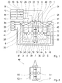
- Fig. 1 is a schematic view of an actuator 1 according to a first embodiment of the invention.
- this actuator 1 is provided in particular in the region of a rotor blade adjustment of a helicopter and is here part of a swash plate control or a single blade control of main or tail rotor blades of the helicopter.
- the actuator 1 but also in other areas of the helicopter or other aircraft, such as an aircraft, are used to implement control functions, such as the control of flaps or oars, for example in the form of a height or aileron.
- the actuator 1 comprises an electromechanical drive device 2, which is divided into several sub-drives 3, 4, 5 and 6 and is connected via a downstream transmission 7 with an output 8 of the actuator 1.
- the output 8 is designed as a control horn, via which the rotational movement generated by the drive direction 2 and translated via the transmission 7 is transmitted further to components connected thereto.
- the partial drives 3 to 6 of the drive device 2 are in the present case independently operable to make the actuator 1 as a redundant system.
- each of the partial drives 3 to 6 via one, its associated supply line (Lane) 9 or 10 or 11 or 12 supplied, each with the connection to an associated generator 13 or 14 or 15 or 16 with each produces a downstream rectifier 17 or 18 or 19 and 20 respectively.
- a power control unit (PCU) 21st or 22 or 23 or 24 is provided, via which in each case the associated part of the drive 3 or 4 or 5 or 6 supplied power is regulated.
- Each power control unit 21 or 22 or 23 or 24 is in turn each associated with an actuator control unit (ACU) 25 or 26 or 27 or 28, which is equipped, for example, with one bipolar transistor with an insulated gate electrode (IGBT) and the associated power control unit 21 or 22 or 23 or 24 regulates.
- ACU actuator control unit
- IGBT insulated gate electrode
- each actuator control unit 25 or 26 or 27 or 28 is connected to two sensors 29 and 30 or 31 and 32 or 33 and 34 or 35 and 36, wherein the sensors 29, 31, 33 and 35 each an angular position of an input shaft 37 of the transmission 7 is detected, while the sensors 30, 32, 34 and 36 respectively determine the angular position of the output 8.
- the Aktuatorkontrollmaschineen 25 to 28 each in the data exchange with associated flight control computers (FCC) 38 to 41.
- the gear 7 is designed in the present case as a planetary gear and is composed of a sun gear 42, a planetary gear 43 and 44 leading planet carrier 45 and a ring gear 46 together.
- the sun gear 42 is non-rotatably arranged on the common input shaft 37 rotatably, which serves a common connection of rotors of the partial drives 3 to 6.
- the planet gears 43 and 44 mesh with both the radially inner sun gear 42, as well as with the surrounding ring gear 46, wherein the planetary gears 43 and 44 leading planet carrier 45 is stopped together with stators of the partial drives 3 to 6, while the ring gear 46 rotatably with the output 8 is connected.
- a drive movement represented jointly by the partial drives 3 to 6 is translated to the output 8 via the transmission 7.
- the transmission 7 is now arranged between the partial drives 3 and 4 on the one side and the partial drives 5 and 6 on the other side, so that the partial drives 3 and 4 are spatially separated from the partial drives 5 and 6. In this way it can be prevented that, for example, a fire on the part of the partial drives 3 and 4 can also directly lead to damage of the partial drives 5 and 6 and vice versa, since these are shielded via the intermediate gear 7 become.
- the partial drives 3 to 6 are each designed as electric motors, each with three phases.
- lying on the respective side of the transmission 7 partial drives 3 and 4 or 5 and 6 are arranged axially one behind the other with respect to the input shaft 37 and accommodated in a respective common housing 47 and 48, respectively.
- FIG. 2 a schematic view of a portion of an actuator 49 according to a second embodiment of the invention.
- the actuator 49 corresponds essentially to the variant Fig. 1 , wherein in contrast to the previous variant, only two partial drives 50 and 51 of an electromechanical drive device 52 are provided, which are separated from each other via the intermediate gear 7.
- Each partial drive 50 or 51 is designed as an electric motor with six phases, each partial drive 50 or 51, as from the other Fig. 3 can be seen, is supplied via two supply lines 9 and 10 or 11 and 12.
- the individual windings, as in Fig. 3 can be seen by the partial drive 50, thereby alternately connected to one of the associated supply lines 9 and 10 or 11 and 12.
- Fig. 4 a schematic view of a portion of an actuator 53 according to a third embodiment of the invention, which in turn largely as the variant Fig. 1 equivalent.
- Fig. 4 Unlike the embodiment according to Fig. 1 and in accordance with the possibility of design according to Fig. 2 and 3 again only two partial drives 50 and 51 are provided, which are designed as electric motors with six phases and are spatially separated from each other via an intermediate gear 54.
- each partial drive 50 or 51 is connected to a common input shaft 55 of the transmission 54 via an intermediate separating clutch 56 and 57, respectively, which are connected to the power control units 21 and 22 or 23 and 24 of the respective partial drives 50 and 51 associated supply lines and 10 or 11 and 12 in terms of control technology, so that the power control units 21 and 22 or 23 and 24 respectively can specifically cause an opening of the separating clutch 56 or 57.
- the respective mechanical connection to the transmission 54 can be interrupted in a targeted manner, and thus one drive can still be represented via the respective other partial drive 51 or 50.
- a cycloidal gear no tooth fractures occur, so that the risk of a possible blockage of the transmission is significantly reduced.
- FIG. 5 a schematic representation of an actuator 62 according to a fourth embodiment of the invention forth.
- this actuator 62 essentially corresponds to the actuator 49 according to FIGS Fig. 2 and 3 , wherein there is a single difference here with respect to the configuration of a transmission 63.
- This transmission 63 is again, as in the variant according to Fig. 4 , designed as a cycloidal gear, but is in this case composed of two gear stages 64 and 65, via which drive movements of the partial drives 50 and 51 are added to the output 8 out.
- the transmission 63 has two input shafts 66 and 67, of which the input shaft 66 is connected to the partial drive 50 and the input shaft 67 is connected to the partial drive 51.
- Each of the input shafts 66 and 67 carries a total of two eccentrics 68 and 69 or 70 and 71, which are connected to a respective cam 72 and 73 or 74 and 75 in conjunction and drive them. All cams 72 to 75 lead common bolt 76th and 77, wherein, however, the cams 72 and 73 are radially in contact with a stationary pin ring 78 in contact, while a pin ring 79 in the case of the cams 74 and 75 rotatably connected to the output 8.
- an actuator according to the invention can thereby reduce its vulnerability and thus increase reliability.
Landscapes
- Engineering & Computer Science (AREA)
- General Engineering & Computer Science (AREA)
- Mechanical Engineering (AREA)
- Aviation & Aerospace Engineering (AREA)
- Automation & Control Theory (AREA)
- Physics & Mathematics (AREA)
- Fluid Mechanics (AREA)
- Retarders (AREA)
- Connection Of Motors, Electrical Generators, Mechanical Devices, And The Like (AREA)
- Transmission Devices (AREA)
Abstract
Description
- Die Erfindung betrifft einen Aktuator für Luftfahrtanwendungen, insbesondere für eine Rotorblattverstellung eines Hubschraubers, umfassend eine elektromechanische Antriebseinrichtung, welche über ein nachgeschaltetes Getriebe mit einem Abtrieb verbunden ist, wobei die Antriebseinrichtung in unabhängig voneinander betreibbare Teilantriebe aufgeteilt ist.
- Bei Luftfahrzeugen kommen Aktuatoren zur Anwendung, um Steuervorgaben eines Piloten in entsprechende Steuerfunktionen umzusetzen. So werden Aktuatoren beispielsweise bei Hubschraubern zur Rotorblattverstellung vorgesehen und leiten beispielsweise im Bereich einer Taumelscheibe gezielt deren axiale Verschiebung zu einem Rotormast und auch deren Neigung quer zum Rotormast ein, so dass im erstgenannten Fall eine kollektive Blattverstellung von Rotorblättern und im zweitgenannten Fall eine zyklische Blattverstellung realisierbar ist. Da ein Ausfall von Aktuatoren, je nachdem welche Steuervorgaben über diese umzusetzen sind, im schlimmsten Fall einen Absturz des jeweiligen Luftfahrzeuges zur Folge haben kann, sind Aktuatoren als redundante Systeme auszuführen, deren zumindest verminderte Funktionsfähigkeit auch bei Ausfall einzelner Komponenten noch sicherzustellen ist.
- Die
US 2010/0150719 A1 offenbart einen Aktuator für eine Rotorblattverstellung bei einem Hubschrauber, wobei sich dieser Aktuator aus einer elektromechanischen Antriebseinrichtung und einem nachgeschalteten Getriebe zusammensetzt. Die Antriebseinrichtung ist dabei als redundanter, mehrphasiger Elektromotor ausgeführt, welcher dementsprechend mehrere unabhängig voneinander betreibbare Teilantriebe in einem Gehäuse vereint. - Ausgehend vom vorstehend beschriebenen Stand der Technik ist es nun die Aufgabe der vorliegenden Erfindung, einen Aktuator für Luftfahrtanwendungen zu schaffen, welcher sich durch eine geringe Schadenanfälligkeit und damit hohe Zuverlässigkeit auszeichnet.
- Diese Aufgabe wird ausgehend vom Oberbegriff des Anspruchs 1 in Verbindung mit dessen kennzeichnenden Merkmalen gelöst. Die hierauf folgenden, abhängigen Ansprüche geben jeweils vorteilhafte Weiterbildungen der Erfindung wieder.
- Gemäß der Erfindung umfasst ein Aktuator für Luftfahrtanwendungen eine elektromechanische Antriebseinrichtung, welche über ein nachgeschaltetes Getriebe mit einem Abtrieb verbunden ist. Dabei ist die Antriebseinrichtung in unabhängig voneinander betreibbare Teilantriebe aufgeteilt. Der erfindungsgemäße Aktuator kommt dabei insbesondere bei einer Rotorblattverstellung eines Hubschraubers zur Anwendung und kann hierbei entweder zur Bewegung einer Taumelscheibe vorgesehen sein, über die eine Blattverstellung der Rotorblätter des Hubschraubers umgesetzt wird, oder aber für eine Einzelblattverstellung vorgesehen sein, wobei der Aktuator dann zwischen dem Einzelblatt und dem Rotorkopf des Haupt- oder Heckrotors angeordnet ist. Der erfindungsgemäße Aktuator kann aber auch in anderen Bereichen und auch bei anderen Luftfahrzeugen, wie Flugzeugen, zur Anwendung kommen und hier einer Klappensteuerung oder der Bedienung eines Ruders, wie einem Querruder oder einem Höhenruder, dienen.
- Im Rahmen der Erfindung werden die unabhängig voneinander betreibbaren Teilantriebe der elektromechanischen Antriebseinrichtung dadurch realisiert, dass jeder Teilantrieb unabhängig mit Energie versorgt und auch geregelt werden kann. So ist jedem Teilantrieb, je nach Anzahl an Phasen, zumindest ein Generator mit nachgeschaltetem Gleichrichter zugeordnet, welcher mit dem Teilantrieb über je eine Versorgungsleitung (Lane) verbunden ist. Insbesondere bei Teilantrieben mit einer hohen Anzahl an Phasen können zur Versorgung der Wicklungen auch mehrere Generatoren, Gleichrichter und Versorgungsleitungen zugeordnet sein. Eine Regelung des einzelnen Teilantriebs wird dabei, je nach Phasenanzahl, über ein oder mehrere Leistungssteuereinheiten (PCU) geregelt, welche wiederum jeweils über je eine zugehörige Aktuatorkontrolleinheit (ACU) gesteuert werden. Insgesamt erfolgt eine Regelung über mehrere Flugkontrollcomputer (FCC), die zudem mit Informationen mehrerer Sensoren versorgt werden.
- Die Erfindung umfasst nun die technische Lehre, dass zumindest zwei Teilantriebe räumlich voneinander getrennt sind, indem das Getriebe zwischen diesen Teilantrieben vorgesehen ist. Mit anderen Worten ist also das Getriebe zwischen zumindest zwei Teilantrieben platziert und trennt diese somit räumlich voneinander, indem der eine Teilantrieb auf der einen Seite des Getriebes und der andere Teilantrieb auf der anderen Seite des Getriebes vorgesehen ist.
- Eine derartige Ausgestaltung eines Aktuators hat dabei den Vorteil, dass Beschädigungen des einen Teilantriebes, beispielsweise durch Feuer, schwerer auch zu einer Beschädigung des anderen Teilantriebes führen können, da ja das Getriebe zwischen beiden Teilantrieben sitzt. Insofern wird hierdurch die Schadensanfälligkeit des Aktuators vermindert und damit insgesamt die Zuverlässigkeit erhöht. Zugleich wird der Aktuator durch die nach wie vor vorhandenen, unabhängig voneinander betreibbaren Teilantriebe als redundantes System gestaltet, bei welchem auch bei einzelnen Ausfällen zumindest noch eine gewisse Steuerfunktion gewährleistet bleibt.
- Bei dem in der
US 2010/0150719 A1 beschriebenen Aktuator sind hingegen die Teilantriebe in einem Motorgehäuse zusammengefasst, was zwar einen kompakten Aufbau ermöglicht, bei bestimmten Schäden an einem Teilantrieb, wie beispielsweise einem Feuer durch Kabelbrand, aber schnell auch zu einer Beschädigung der übrigen Teilantriebe führen kann. Im Extremfall kann dies einen Ausfall des kompletten Aktuators zur Folge haben. - Entsprechend einer Ausführungsform der Erfindung ist beidseitig des Getriebes jeweils ein Teilantrieb vorgesehen. In Weiterbildung dieser Ausführungsform ist dabei jeder Teilantrieb jeweils als Elektromotor mit sechs Phasen ausgeführt. Es werden dabei bevorzugt zwei 3-phasige Motoren zu einem Elektromotor zusammengefasst, was einen kompakten Aufbau ermöglicht. Weiter bevorzugt sind dem Elektromotor mit sechs Phasen dabei zwei Versorgungsleitungen (Lanes), zwei Leistungssteuereinheiten (PCUs) und zwei Aktuatorkontrolleinheiten (ACUs) zugeordnet, die jeweils dreien der sechs Phasen zugehörig sind. Des Weiteren wird insbesondere eine innere Redundanz gebildet, indem innerhalb des 6-phasigen Elektromotors eine räumliche, thermische, magnetische und elektrische Trennung der einzelnen Phasen vorgenommen wird, indem die den Versorgungsleitungen, PCUs und ACUs zugeordneten Wicklungen alternierend angeordnet sind.
- Entsprechend einer alternativen Ausgestaltungsmöglichkeit sind beidseitig des Getriebes jeweils zwei Teilantriebe vorgesehen, wobei diese Teilantriebe dabei bevorzugt jeweils als Elektromotor mit drei Phasen ausgeführt sind. Hierdurch baut das System zwar in axialer Richtung etwas länger, die auf einer Seite in Summe ebenfalls sechs Phasen bildenden Elektromotoren sind jedoch ebenfalls voneinander getrennt.
- Der eine oder auch die mehreren auf einer Seite des Getriebes vorgesehenen Teilantriebe sind im Sinne der Erfindung dann insbesondere in einem Gehäuse gekapselt, um eine Beeinträchtigung des oder der Teilantriebe von außen möglichst zu verhindern.
- Es ist eine weitere Ausführungsform der Erfindung, dass den Teilantrieben eine gemeinsame Eingangswelle des Getriebes zugeordnet ist. Alle Teilantriebe der elektromechanischen Antriebseinrichtung treiben also über ein und dieselbe Eingangswelle in das Getriebe ein. Weiter bevorzugt ist zwischen der Eingangswelle und dem mindestens einen auf der jeweiligen Seite des Getriebes vorgesehenen Teilantrieb je eine Trennkupplung angeordnet, über welche eine mechanische Verbindung der Eingangswelle zu diesem mindestens einen Teilantrieb unterbrochen werden kann. Hierdurch kann ein weiterer Betrieb des Aktuators auch dann sichergestellt werden, wenn der eine oder die mehreren auf dieser Seite des Getriebes vorgesehenen Teilantriebe blockieren. In diesem Fall wird über die jeweilige Trennkupplung dann die mechanische Verbindung unterbrochen, so dass ein Antrieb über den oder die auf der jeweils anderen Seite des Getriebes sitzenden Teilantriebe nach wie vor realisiert werden kann.
- Gemäß einer weiteren Ausführungsform der Erfindung verfügt das Getriebe über zwei Eingangswellen, wobei die eine Eingangswelle dem mindestens einen auf der einen Seite des Getriebes liegenden Teilantrieb und die andere Eingangswelle dem mindestens einen auf der anderen Seite des Getriebes liegenden Teilantrieb zugeordnet ist. Das Getriebe summiert dann Antriebsleistungen der Teilantriebe zum Abtrieb auf. Auch hierdurch kann beim Blockieren eines oder mehrerer Teilantriebe auf einer Seite nach wie vor eine ggf. eingeschränkte Steuerfunktion des Aktuators realisiert werden.
- In Weiterbildung der Erfindung, ggf. in Weiterbildung der vorgenannten Ausführungsform, setzt sich das Getriebe aus mehreren Getriebestufen zusammen. Hierdurch kann zum einen eine geeignete Übersetzung von Antriebsbewegungen der Teilantriebe realisiert werden, sowie zum anderen, bei geeigneter Verschachtelung der Getriebestufen, auch dann eine Steuerfunktion garantiert werden, wenn eine Getriebestufe blockiert.
- Entsprechend einer Ausgestaltungsmöglichkeit der Erfindung ist das Getriebe als Planetengetriebe oder als Zykloidgetriebe ausgeführt. In beiden Fällen kann ein belastbares Getriebe verwirklicht werden, wobei bei einem Zykloidgetriebe zudem die Gefahr einer Blockade durch Zahnbrüche vermindert ist.
- Die Erfindung ist nicht auf die angegebene Kombination der Merkmale des Hauptanspruchs oder der hiervon abhängigen Ansprüche beschränkt. Es ergeben sich darüber hinaus Möglichkeiten, einzelne Merkmale, auch soweit sie aus den Ansprüchen, der nachfolgenden Beschreibung bevorzugter Ausführungsformen der Erfindung oder unmittelbar aus den Zeichnungen hervorgehen, miteinander zu kombinieren. Die Bezugnahme der Ansprüche auf die Zeichnungen durch Verwendung von Bezugszeichen soll den Schutzumfang der Ansprüche nicht beschränken.
- Bevorzugte Ausführungsformen der Erfindung, die nachfolgend erläutert werden, sind in den Zeichnungen dargestellt. Es zeigt:
- Fig. 1
- eine schematische Ansicht eines Aktuators entsprechend einer ersten Ausführungsform der Erfindung;
- Fig. 2
- einen Teil eines Aktuators gemäß einer zweiten Ausgestaltungsmöglichkeit der Erfindung;
- Fig. 3
- eine weitere schematische Ansicht eines Teils des Aktuators aus
Fig. 2 ; - Fig. 4
- eine schematische Darstellung eines Aktuators entsprechend einer dritten Ausführungsform der Erfindung; und
- Fig. 5
- eine schematische Ansicht eines Aktuators gemäß einer vierten Ausgestaltungsmöglichkeit der Erfindung.
- Aus
Fig. 1 geht eine schematische Ansicht eines Aktuators 1 entsprechend einer ersten Ausführungsform der Erfindung hervor. Dabei ist dieser Aktuator 1 insbesondere im Bereich einer Rotorblattverstellung eines Hubschraubers vorgesehen und ist hier Teil einer Taumelscheibensteuerung oder einer Einzelblattsteuerung von Haupt- oder Heckrotorblättern des Hubschraubers. Alternativ dazu kann der Aktuator 1 aber auch in anderen Bereichen des Hubschraubers oder auch eines anderen Luftfahrzeuges, wie einem Flugzeug, zur Anwendung kommen, um Steuerfunktionen umzusetzen, wie die Steuerung von Klappen oder Rudern, beispielsweise in Form eines Höhen- oder Querruders. - Wie in
Fig. 1 zu erkennen ist, umfasst der Aktuator 1 eine elektromechanische Antriebseinrichtung 2, die in mehrere Teilantriebe 3, 4, 5 und 6 aufgeteilt ist und über ein nachgeschaltetes Getriebe 7 mit einem Abtrieb 8 des Aktuators 1 verbunden ist. Der Abtrieb 8 ist vorliegend dabei als Steuerhorn gestaltet, über welchen die durch die Antriebsrichtung 2 erzeugte und über das Getriebe 7 übersetzte Drehbewegung weiter auf hieran angebundene Komponenten übertragen wird. - Die Teilantriebe 3 bis 6 der Antriebseinrichtung 2 sind vorliegend unabhängig voneinander betreibbar, um den Aktuator 1 als redundantes System zu gestalten. So wird jeder der Teilantriebe 3 bis 6 über je eine, ihm zugeordnete Versorgungsleitung (Lane) 9 bzw. 10 bzw. 11 bzw. 12 versorgt, die jeweils die Verbindung zu je einem zugehörigen Generator 13 bzw. 14 bzw. 15 bzw. 16 mit je einem nachgeschalteten Gleichrichter 17 bzw. 18 bzw. 19 bzw. 20 herstellt. Innerhalb jeder Versorgungsleitung 9 bzw. 10 bzw. 11 bzw. 12 ist zudem je eine Leistungssteuereinheit (PCU) 21 bzw. 22 bzw. 23 bzw. 24 vorgesehen, über welche jeweils die dem zugehörigen Teilantrieb 3 bzw. 4 bzw. 5 bzw. 6 zugeführte Leistung geregelt wird.
- Jeder Leistungssteuereinheit 21 bzw. 22 bzw. 23 bzw. 24 ist wiederum je eine Aktuatorkontrolleinheit (ACU) 25 bzw. 26 bzw. 27 bzw. 28 zugeordnet, welche z.B. mit je einem Bipolartransistor mit isolierter Gate-Elektrode (IGBT) ausgestattet ist und die zugehörige Leistungssteuereinheit 21 bzw. 22 bzw. 23 bzw. 24 regelt. Zu diesem Zweck ist jede Aktuatorkontrolleinheit 25 bzw. 26 bzw. 27 bzw. 28 mit jeweils zwei Sensoren 29 und 30 bzw. 31 und 32 bzw. 33 und 34 bzw. 35 und 36 verbunden, wobei über die Sensoren 29, 31, 33 und 35 jeweils eine Winkelposition einer Eingangswelle 37 des Getriebes 7 erfasst wird, während die Sensoren 30, 32 , 34 und 36 jeweils die Winkelposition des Abtriebes 8 ermitteln. Wie zudem in
Fig. 1 zu erkennen ist, stehen die Aktuatorkontrolleinheiten 25 bis 28 jeweils im Datenaustausch mit zugehörigen Flugkontrollcomputern (FCC) 38 bis 41. - Das Getriebe 7 ist im vorliegenden Fall als Planetengetriebe gestaltet und setzt sich aus einem Sonnenrad 42, einem mehrere Planetenräder 43 und 44 führenden Planetenträger 45 und einem Hohlrad 46 zusammen. Dabei ist das Sonnenrad 42 drehfest auf der gemeinsamen Eingangswelle 37 drehfest angeordnet, die einer gemeinsamen Anbindung von Rotoren der Teilantriebe 3 bis 6 dient. Die Planetenräder 43 und 44 kämmen jeweils sowohl mit dem radial innenliegenden Sonnenrad 42, als auch mit dem umliegenden Hohlrad 46, wobei der die Planetenräder 43 und 44 führende Planetenträger 45 gemeinsam mit Statoren der Teilantriebe 3 bis 6 stillgesetzt ist, während das Hohlrad 46 drehfest mit dem Abtrieb 8 verbunden ist. Über das Getriebe 7 wird dabei eine gemeinsam durch die Teilantriebe 3 bis 6 dargestellte Antriebsbewegung ins Langsame auf den Abtrieb 8 übersetzt.
- Als Besonderheit ist das Getriebe 7 nun zwischen den Teilantrieben 3 und 4 auf der einen Seite und den Teilantrieben 5 und 6 auf der anderen Seite angeordnet, so dass die Teilantriebe 3 und 4 räumlich von den Teilantrieben 5 und 6 getrennt werden. Hierdurch kann verhindert werden, dass beispielsweise ein Feuer auf Seiten der Teilantriebe 3 und 4 direkt auch zu einer Beschädigung der Teilantriebe 5 und 6 und umgekehrt führen kann, da diese über das zwischenliegende Getriebe 7 abgeschirmt werden. Die Teilantriebe 3 bis 6 sind dabei jeweils als Elektromotoren mit je drei Phasen ausgeführt. Zudem sind die auf derjeweiligen Seite des Getriebes 7 liegenden Teilantriebe 3 und 4 bzw. 5 und 6 in Bezug auf die Eingangswelle 37 axial hintereinanderliegend angeordnet und in je einem gemeinsamen Gehäuse 47 bzw. 48 aufgenommen.
- Ferner geht aus
Fig. 2 eine schematische Ansicht eines Teils eines Aktuators 49 entsprechend einer zweiten Ausgestaltungsmöglichkeit der Erfindung hervor. Der Aktuator 49 entspricht dabei im Wesentlichen der Variante nachFig. 1 , wobei im Unterschied zu der vorhergehenden Variante insgesamt nur zwei Teilantriebe 50 und 51 einer elektromechanischen Antriebseinrichtung 52 vorgesehen sind, die dabei über das zwischenliegende Getriebe 7 voneinander getrennt sind. Jeder Teilantrieb 50 bzw. 51 ist dabei als Elektromotor mit je sechs Phasen ausgeführt, wobei jeder Teilantrieb 50 bzw. 51, wie aus der weiterenFig. 3 zu erkennen ist, über je zwei Versorgungsleitungen 9 und 10 bzw. 11 und 12 versorgt wird. Innerhalb des jeweiligen Teilantriebes 50 bzw. 51 sind die einzelnen Wicklungen, wie inFig. 3 anhand des Teilantriebes 50 zu erkennen ist, dabei alternierend mit je einer der zugehörigen Versorgungsleitungen 9 und 10 bzw. 11 und 12 verbunden. Insofern sind im Falle der Ausführungsform nach denFig. 2 und3 zwei Teilantriebe nachFig. 1 zu je einem Teilantrieb 50 bzw. 51 zusammengefasst. Wesentlich ist dabei, dass innerhalb des jeweiligen Teilantriebes 50 bzw. 51 auch eine innere Redundanz gebildet wird, indem die einzelnen Phasen räumlich, thermisch, magnetisch und elektrisch voneinander getrennt sind. Hierdurch kann der einzelne Teilantrieb 50 bzw. 51 auch dann noch weitestgehend betrieben werden, wenn eine der Phasen ausfällt. Im Übrigen entspricht die Variante nach denFig. 2 und3 dann der Ausführungsform nachFig. 1 , so dass auf das hierzu Beschriebene Bezug genommen wird. - Des Weiteren zeigt
Fig. 4 eine schematische Ansicht eines Teils eines Aktuators 53 entsprechend einer dritten Ausführungsform der Erfindung, welche dabei wiederum weitestgehend der Variante nachFig. 1 entspricht. Im Unterschied zu der Ausführungsform nachFig. 1 und in Übereinstimmung mit der Ausgestaltungsmöglichkeit nach denFig. 2 und3 sind dabei wiederum nur zwei Teilantriebe 50 und 51 vorgesehen, die als Elektromotoren mit sechs Phasen ausgeführt sind und über ein zwischenliegendes Getriebe 54 räumlich voneinander getrennt werden. - Allerdings ist jeder Teilantrieb 50 bzw. 51 mit einer gemeinsamen Eingangswelle 55 des Getriebes 54 über je eine zwischenliegende Trennkupplung 56 bzw. 57 verbunden, welche mit den Leistungssteuereinheiten 21 und 22 bzw. 23 und 24 der dem jeweiligen Teilantrieb 50 bzw. 51 zugeordneten Versorgungsleitungen 9 und 10 bzw. 11 und 12 regelungstechnisch in Verbindung steht, so dass die Leistungssteuereinheiten 21 und 22 bzw. 23 und 24 jeweils gezielt ein Öffnen der Trennkupplung 56 bzw. 57 hervorrufen können. Hierdurch kann bei Blockieren einer der Teilantriebe 50 oder 51 gezielt die jeweilige mechanische Verbindung zum Getriebe 54 unterbrochen werden und somit noch ein Antrieb über den jeweils anderen Teilantrieb 51 oder 50 dargestellt werden.
- Als weiterer Unterschied ist das Getriebe 54 im Falle der Variante nach
Fig. 4 als Zykloidgetriebe ausgeführt, bei welchem auf der Eingangswelle 55 zwei Exzenter 58 und 59 vorgesehen sind, die über je eine Kurvenscheibe 60 bzw. 61 mit dem Abtrieb 8 gekoppelt sind. Bei einem Zykloidgetriebe treten keine Zahnbrüche auf, so dass die Gefahr einer möglichen Blockade des Getriebes deutlich reduziert ist. - Schließlich geht aus
Fig. 5 noch eine schematische Darstellung eines Aktuators 62 gemäß einer vierten Ausführungsform der Erfindung hervor. Dabei entspricht dieser Aktuator 62 im Wesentlichen dem Aktuator 49 nach denFig. 2 und3 , wobei ein einziger Unterschied hierbei bezüglich der Ausgestaltung eines Getriebes 63 besteht. Dieses Getriebe 63 ist nämlich erneut, wie schon bei der Variante nachFig. 4 , als Zykloidgetriebe gestaltet, setzt sich aber in diesem Fall aus zwei Getriebestufen 64 und 65 zusammen, über welche Antriebsbewegungen der Teilantriebe 50 und 51 zum Abtrieb 8 hin aufsummiert werden. Hierzu verfügt das Getriebe 63 über zwei Eingangswellen 66 und 67, von welchen die Eingangswelle 66 mit dem Teilantrieb 50 und die Eingangswelle 67 mit dem Teilantrieb 51 verbunden ist. Jede der Eingangswellen 66 und 67 trägt jeweils insgesamt zwei Exzenter 68 und 69 bzw. 70 und 71, die mit je einer Kurvenscheibe 72 bzw. 73 bzw. 74 bzw. 75 in Verbindung stehen und diese antreiben. Alle Kurvenscheiben 72 bis 75 führen dabei gemeinsame Bolzen 76 und 77, wobei allerdings die Kurvenscheiben 72 und 73 radial umliegend mit einem feststehenden Bolzenring 78 in Kontakt stehen, während ein Bolzenring 79 im Falle der Kurvenscheiben 74 und 75 drehfest mit dem Abtrieb 8 verbunden ist. Durch diesen Aufbau des Getriebes 63 wird dabei erreicht, dass auch bei Blockieren einer der beiden Getriebestufen 64 oder 65 noch eine evtl. eingeschränkte Steuerfunktion über die jeweils andere Getriebestufe 65 oder 64 realisiert werden kann. - Mittels der erfindungsgemäßen Ausgestaltungen eines Aktuators kann dabei dessen Schadenanfälligkeit reduziert und damit eine Zuverlässigkeit gesteigert werden.
-
- 1
- Aktuator
- 2
- Antriebseinrichtung
- 3
- Teilantrieb
- 4
- Teilantrieb
- 5
- Teilantrieb
- 6
- Teilantrieb
- 7
- Getriebe
- 8
- Abtrieb
- 9
- Versorgungsleitung
- 10
- Versorgungsleitung
- 11
- Versorgungsleitung
- 12
- Versorgungsleitung
- 13
- Generator
- 14
- Generator
- 15
- Generator
- 16
- Generator
- 17
- Gleichrichter
- 18
- Gleichrichter
- 19
- Gleichrichter
- 20
- Gleichrichter
- 21
- Leistungssteuereinheit
- 22
- Leistungssteuereinheit
- 23
- Leistungssteuereinheit
- 24
- Leistungssteuereinheit
- 25
- Aktuatorkontrolleinheit
- 26
- Aktuatorkontrolleinheit
- 27
- Aktuatorkontrolleinheit
- 28
- Aktuatorkontrolleinheit
- 29
- Sensor
- 30
- Sensor
- 31
- Sensor
- 32
- Sensor
- 33
- Sensor
- 34
- Sensor
- 35
- Sensor
- 36
- Sensor
- 37
- Eingangswelle
- 38
- Flugkontrollcomputer
- 39
- Flugkontrollcomputer
- 40
- Flugkontrollcomputer
- 41
- Flugkontrollcomputer
- 42
- Sonnenrad
- 43
- Planetenrad
- 44
- Planetenrad
- 45
- Planetenträger
- 46
- Hohlrad
- 47
- Gehäuse
- 48
- Gehäuse
- 49
- Aktuator
- 50
- Teilantrieb
- 51
- Teilantrieb
- 52
- Antriebseinrichtung
- 53
- Aktuator
- 54
- Getriebe
- 55
- Eingangswelle
- 56
- Trennkupplung
- 57
- Trennkupplung
- 58
- Exzenter
- 59
- Exzenter
- 60
- Kurvenscheibe
- 61
- Kurvenscheibe
- 62
- Aktuator
- 63
- Getriebe
- 64
- Getriebestufe
- 65
- Getriebestufe
- 66
- Eingangswelle
- 67
- Eingangswelle
- 68
- Exzenter
- 69
- Exzenter
- 70
- Exzenter
- 71
- Exzenter
- 72
- Kurvenscheibe
- 73
- Kurvenscheibe
- 74
- Kurvenscheibe
- 75
- Kurvenscheibe
- 76
- Bolzen
- 77
- Bolzen
- 78
- Bolzenring
- 79
- Bolzenring
Claims (10)
- Aktuator (1; 49; 53; 62) für Luftfahrtanwendungen, insbesondere für eine Rotorblattverstellung eines Hubschraubers, umfassend eine elektromechanische Antriebseinrichtung (2; 52), welche über ein nachgeschaltetes Getriebe (7; 54; 63) mit einem Abtrieb (8) verbunden ist, wobei die Antriebseinrichtung (2; 52) in unabhängig voneinander betreibbare Teilantriebe (3, 4, 5, 6; 50, 51) aufgeteilt ist, dadurch gekennzeichnet, dass zumindest zwei Teilantriebe (3, 4, 5, 6; 50, 51) räumlich voneinander getrennt sind, indem das Getriebe (7; 54; 63) zwischen diesen Teilantrieben (3, 4, 5, 6; 50, 51) vorgesehen ist.
- Aktuator (49; 53; 62) nach Anspruch 1, dadurch gekennzeichnet, dass beidseitig des Getriebes (7; 54; 63) jeweils ein Teilantrieb (50, 51) vorgesehen ist.
- Aktuator (49; 53; 62) nach Anspruch 2, dadurch gekennzeichnet, dass jeder Teilantrieb (50, 51) jeweils als Elektromotor mit sechs Phasen ausgeführt ist.
- Aktuator (1) nach Anspruch 1, dadurch gekennzeichnet, dass beidseitig des Getriebes (7) jeweils zwei Teilantriebe (3, 4, 5, 6) vorgesehen sind.
- Aktuator (1) nach Anspruch 4, dadurch gekennzeichnet, dass jeder Teilantrieb (3, 4, 5, 6) jeweils als Elektromotor mit drei Phasen ausgeführt ist.
- Aktuator (1; 49; 53; 62) nach Anspruch 1, dadurch gekennzeichnet, dass den Teilantrieben (3, 4, 5, 6; 50, 51) eine gemeinsame Eingangswelle (37; 55) des Getriebes (7; 54) zugeordnet ist.
- Aktuator (53) nach Anspruch 6, dadurch gekennzeichnet, dass zwischen der Eingangswelle (55) und dem mindestens einen, auf der jeweiligen Seite des Getriebes (54) vorgesehenen Teilantrieb (50, 51) je eine Trennkupplung (56, 57) angeordnet ist, über welche eine mechanische Verbindung der Eingangswelle (55) zu diesem mindestens einen Teilantrieb (50, 51) unterbrechbar ist.
- Aktuator (62) nach Anspruch 1, dadurch gekennzeichnet, dass das Getriebe (63) über zwei Eingangswellen (66, 67) verfügt, wobei die eine Eingangswelle (66) dem mindestens einen auf der einen Seite des Getriebes (63) liegenden Teilantrieb (50) und die andere Eingangswelle (67) dem mindestens einen auf der anderen Seite des Getriebes (63) liegenden Teilantrieb (51) zugeordnet ist, und wobei das Getriebe (63) Antriebsleistungen der Teilantriebe (50, 51) zum Abtrieb (8) aufsummiert.
- Aktuator (62) nach Anspruch 1, dadurch gekennzeichnet, dass sich das Getriebe (63) aus mehreren Getriebestufen (64, 65) zusammensetzt.
- Aktuator (1; 49; 53; 62) nach Anspruch 1, dadurch gekennzeichnet, dass das Getriebe (7; 54; 63) als Planetengetriebe oder als Zykloidgetriebe ausgeführt ist.
Applications Claiming Priority (1)
| Application Number | Priority Date | Filing Date | Title |
|---|---|---|---|
| DE102015203411.9A DE102015203411A1 (de) | 2015-02-26 | 2015-02-26 | Aktuator für Luftfahrtanwendungen |
Publications (2)
| Publication Number | Publication Date |
|---|---|
| EP3061687A1 true EP3061687A1 (de) | 2016-08-31 |
| EP3061687B1 EP3061687B1 (de) | 2019-07-17 |
Family
ID=55237563
Family Applications (1)
| Application Number | Title | Priority Date | Filing Date |
|---|---|---|---|
| EP16152866.6A Active EP3061687B1 (de) | 2015-02-26 | 2016-01-27 | Aktuator für luftfahrtanwendungen |
Country Status (3)
| Country | Link |
|---|---|
| US (2) | US10421539B2 (de) |
| EP (1) | EP3061687B1 (de) |
| DE (1) | DE102015203411A1 (de) |
Cited By (2)
| Publication number | Priority date | Publication date | Assignee | Title |
|---|---|---|---|---|
| CN109606646A (zh) * | 2018-11-06 | 2019-04-12 | 珠海隆华直升机科技有限公司 | 直升机旋转式电动直驱变距尾桨总成及直升机 |
| WO2019215019A1 (de) * | 2018-05-08 | 2019-11-14 | Zf Friedrichshafen Ag | Elektromechanischer aktor zur individuellen blatteinstellung eines kollektiv-offsets für einen hubschrauber |
Families Citing this family (3)
| Publication number | Priority date | Publication date | Assignee | Title |
|---|---|---|---|---|
| DE102017118771B4 (de) * | 2017-08-17 | 2020-01-02 | Deutsches Zentrum für Luft- und Raumfahrt e.V. | Abtriebsstation für die Betätigung einer Klappe an einem Flugzeugflügel und Flugzeug mit solchen Abtriebsstationen |
| US11608161B2 (en) * | 2020-04-08 | 2023-03-21 | The Boeing Company | Flap actuation systems and related methods |
| DE102020204915A1 (de) | 2020-04-17 | 2021-10-21 | Zf Friedrichshafen Ag | Aktuator für Luftfahrtanwendungen |
Citations (5)
| Publication number | Priority date | Publication date | Assignee | Title |
|---|---|---|---|---|
| US3679956A (en) * | 1970-02-02 | 1972-07-25 | Ltv Electrosystems Inc | Multiple servomotor actuator |
| US4304375A (en) * | 1979-05-17 | 1981-12-08 | Textron Inc. | Electrically controlled elevator |
| US20070051847A1 (en) * | 2005-09-08 | 2007-03-08 | Honeywell International, Inc. | Electromechanical actuator including redundant, dissimilar position feedback |
| US20100150719A1 (en) | 2008-12-12 | 2010-06-17 | Karem Aircraft, Inc. | Swashplateless rotorcraft with fault tolerant linear electric actuator |
| DE102013202221A1 (de) * | 2012-03-29 | 2013-10-02 | Mitsubishi Electric Corporation | Elektromotorantriebsvorrichtung mit Ausfalldetektionsschaltung und Ausfalldetektionsverfahren für Elektromotorantriebsvorrichtung mit Ausfalldetektionsschaltung |
Family Cites Families (14)
| Publication number | Priority date | Publication date | Assignee | Title |
|---|---|---|---|---|
| US3530355A (en) * | 1968-10-14 | 1970-09-22 | John Alfred Hodgkins | Automatic control systems |
| US4289996A (en) * | 1978-08-29 | 1981-09-15 | Frazer Nash Limited | Actuators |
| DE60231675D1 (de) * | 2001-06-01 | 2009-05-07 | Ihi Aerospace Co Ltd | Elektromotorischer Stellantrieb und Verfahren zum Steuern desselben |
| FR2832685A1 (fr) * | 2001-11-23 | 2003-05-30 | Conception & Dev Michelin Sa | Direction electrique pour vehicule, a redondance triple |
| FR2836668B1 (fr) * | 2002-03-04 | 2004-12-03 | Messier Bugatti | Dispositif d'accrochage, notamment pour l'accrochage d'un train d'atterrissage d'aeronef ou d'une trappe de train d'atterrissage d'aeronef, et procede de fonctionnement dudit dispositif |
| US6791215B2 (en) * | 2002-06-05 | 2004-09-14 | Board Of Regents The University Of Texas System | Fault tolerant linear actuator |
| WO2007102763A1 (en) * | 2006-03-09 | 2007-09-13 | Volvo Technology Corporation | Hybrid powertrain |
| DE102009001393B4 (de) * | 2009-03-09 | 2019-12-19 | Zf Friedrichshafen Ag | Steuerstangenanordnung zum Verstellen von Rotorblättern eines Hubschraubers |
| DE202009006227U1 (de) * | 2009-04-30 | 2010-10-21 | Dr. Fritz Faulhaber Gmbh & Co. Kg | Elektrischer Stellantrieb |
| DE112010004598B4 (de) * | 2009-11-27 | 2023-02-02 | Stoneridge Control Devices, Inc. | Elektrisch gesteuertes (Shift-By-Wire) Fahrstufenauswahlsystem für ein Schaltgetriebe,zugehöriger Aktuator und Verfahren zum Betätigen |
| US10843796B2 (en) * | 2012-02-10 | 2020-11-24 | Merlin Technology, Inc. | Rotorcraft advanced autopilot control arrangement and methods |
| US9938006B2 (en) * | 2012-08-28 | 2018-04-10 | Bell Helicopter Textron Inc. | Actuation system for an active element in a rotor blade |
| DE102013206061B4 (de) * | 2013-04-05 | 2024-04-25 | Airbus Helicopters Technik Gmbh | Betätigungsvorrichtung einer aerodynamisch wirksamen Fläche |
| JP6119561B2 (ja) * | 2013-11-01 | 2017-04-26 | トヨタ自動車株式会社 | ハイブリッド車両用駆動装置 |
-
2015
- 2015-02-26 DE DE102015203411.9A patent/DE102015203411A1/de not_active Withdrawn
-
2016
- 2016-01-27 EP EP16152866.6A patent/EP3061687B1/de active Active
- 2016-02-25 US US15/053,178 patent/US10421539B2/en active Active
-
2019
- 2019-08-27 US US16/552,405 patent/US11008097B2/en active Active
Patent Citations (5)
| Publication number | Priority date | Publication date | Assignee | Title |
|---|---|---|---|---|
| US3679956A (en) * | 1970-02-02 | 1972-07-25 | Ltv Electrosystems Inc | Multiple servomotor actuator |
| US4304375A (en) * | 1979-05-17 | 1981-12-08 | Textron Inc. | Electrically controlled elevator |
| US20070051847A1 (en) * | 2005-09-08 | 2007-03-08 | Honeywell International, Inc. | Electromechanical actuator including redundant, dissimilar position feedback |
| US20100150719A1 (en) | 2008-12-12 | 2010-06-17 | Karem Aircraft, Inc. | Swashplateless rotorcraft with fault tolerant linear electric actuator |
| DE102013202221A1 (de) * | 2012-03-29 | 2013-10-02 | Mitsubishi Electric Corporation | Elektromotorantriebsvorrichtung mit Ausfalldetektionsschaltung und Ausfalldetektionsverfahren für Elektromotorantriebsvorrichtung mit Ausfalldetektionsschaltung |
Cited By (3)
| Publication number | Priority date | Publication date | Assignee | Title |
|---|---|---|---|---|
| WO2019215019A1 (de) * | 2018-05-08 | 2019-11-14 | Zf Friedrichshafen Ag | Elektromechanischer aktor zur individuellen blatteinstellung eines kollektiv-offsets für einen hubschrauber |
| US11745864B2 (en) | 2018-05-08 | 2023-09-05 | Airbus Helicopters Technik Gmbh | Electromechanical actuator for setting a collective offset for a helicopter on a blade-specific basis |
| CN109606646A (zh) * | 2018-11-06 | 2019-04-12 | 珠海隆华直升机科技有限公司 | 直升机旋转式电动直驱变距尾桨总成及直升机 |
Also Published As
| Publication number | Publication date |
|---|---|
| US11008097B2 (en) | 2021-05-18 |
| DE102015203411A1 (de) | 2016-09-01 |
| US20160251079A1 (en) | 2016-09-01 |
| US20190382108A1 (en) | 2019-12-19 |
| EP3061687B1 (de) | 2019-07-17 |
| US10421539B2 (en) | 2019-09-24 |
Similar Documents
| Publication | Publication Date | Title |
|---|---|---|
| EP3061687B1 (de) | Aktuator für luftfahrtanwendungen | |
| WO2017114643A1 (de) | Redundantes, elektrisches antriebssystem zum antreiben eines vortriebsmittels eines luftfahrzeugs und verfahren zum antreiben des vortriebsmittels | |
| EP3297919B1 (de) | System zum bereitstellen von kinetischer energie für ein antriebssystem eines luftfahrzeugs | |
| EP4136023B1 (de) | Aktuator für luftfahrtanwendungen | |
| DE102019112021A1 (de) | Hub-Dreh-Modul | |
| DE102019218026A1 (de) | Elektrische servolenkvorrichtung | |
| EP3921231B1 (de) | Antrieb, insbesondere für den hauptrotor eines drehflüglers | |
| EP4015377B1 (de) | Drehflügler mit einem hybridantrieb zum antreiben eines haupt- und/oder heckrotors des drehflüglers | |
| AT523262A4 (de) | Vorrichtung zur Verstellung der Neigung von Rotorblättern eines Rotors | |
| DE102016015383A1 (de) | Aktuator in einem Fahrwerkssystem eines Fluggeräts | |
| EP2449288B1 (de) | Elektromechanische linearstelleinheit | |
| DE102012005346A1 (de) | Flugzeug | |
| DE102014206230A1 (de) | Schwingungsdämpfer | |
| DE102017215269A1 (de) | Elektromotor, Antriebssystem und Verfahren zum Antreiben von Einzelpropellern eines Doppelpropellersystems | |
| EP3963614B1 (de) | Verfahren zum durchführen eine umschaltung eines laststufenschalters mittels eines antriebssystems und antriebssystem für einen laststufenschalter | |
| DE102014010356B4 (de) | Flugzeug | |
| DE102021103936B4 (de) | Stellantrieb für eine Steuerfläche eines Luftfahrzeugs | |
| DE102018207141A1 (de) | System zur Steuerung eines elektromechanischen Aktors zur blattindividuellen Einstellung eines Kollektiv-Offsets für einen Hubschrauber | |
| WO2015169276A1 (de) | Antrieb für eine mobile vorrichtung, mobile vorrichtung und steuerungsverfahren | |
| EP3802019B1 (de) | Antriebsvorrichtung für einen manipulator | |
| DE102019115322A1 (de) | Feedback-Aktuator für eine Lenkeinrichtung | |
| DE102011113952B4 (de) | Stellgerätesystem für Luftfahrzeuge | |
| DE102023134800A1 (de) | Antriebseinheit, System, Verwendung und Luftfahrzeug | |
| DE102021201408A1 (de) | Verfahren zum Betrieb einer Lenkvorrichtung | |
| DE102024117719A1 (de) | Elektromotor für ein Luftfahrzeug und Luftfahrzeug |
Legal Events
| Date | Code | Title | Description |
|---|---|---|---|
| PUAI | Public reference made under article 153(3) epc to a published international application that has entered the european phase |
Free format text: ORIGINAL CODE: 0009012 |
|
| AK | Designated contracting states |
Kind code of ref document: A1 Designated state(s): AL AT BE BG CH CY CZ DE DK EE ES FI FR GB GR HR HU IE IS IT LI LT LU LV MC MK MT NL NO PL PT RO RS SE SI SK SM TR |
|
| AX | Request for extension of the european patent |
Extension state: BA ME |
|
| STAA | Information on the status of an ep patent application or granted ep patent |
Free format text: STATUS: REQUEST FOR EXAMINATION WAS MADE |
|
| 17P | Request for examination filed |
Effective date: 20161205 |
|
| STAA | Information on the status of an ep patent application or granted ep patent |
Free format text: STATUS: EXAMINATION IS IN PROGRESS |
|
| 17Q | First examination report despatched |
Effective date: 20171214 |
|
| GRAJ | Information related to disapproval of communication of intention to grant by the applicant or resumption of examination proceedings by the epo deleted |
Free format text: ORIGINAL CODE: EPIDOSDIGR1 |
|
| STAA | Information on the status of an ep patent application or granted ep patent |
Free format text: STATUS: GRANT OF PATENT IS INTENDED |
|
| GRAP | Despatch of communication of intention to grant a patent |
Free format text: ORIGINAL CODE: EPIDOSNIGR1 |
|
| INTG | Intention to grant announced |
Effective date: 20190206 |
|
| GRAS | Grant fee paid |
Free format text: ORIGINAL CODE: EPIDOSNIGR3 |
|
| GRAA | (expected) grant |
Free format text: ORIGINAL CODE: 0009210 |
|
| STAA | Information on the status of an ep patent application or granted ep patent |
Free format text: STATUS: THE PATENT HAS BEEN GRANTED |
|
| AK | Designated contracting states |
Kind code of ref document: B1 Designated state(s): AL AT BE BG CH CY CZ DE DK EE ES FI FR GB GR HR HU IE IS IT LI LT LU LV MC MK MT NL NO PL PT RO RS SE SI SK SM TR |
|
| REG | Reference to a national code |
Ref country code: GB Ref legal event code: FG4D Free format text: NOT ENGLISH |
|
| REG | Reference to a national code |
Ref country code: CH Ref legal event code: EP |
|
| REG | Reference to a national code |
Ref country code: IE Ref legal event code: FG4D Free format text: LANGUAGE OF EP DOCUMENT: GERMAN |
|
| REG | Reference to a national code |
Ref country code: DE Ref legal event code: R096 Ref document number: 502016005540 Country of ref document: DE |
|
| REG | Reference to a national code |
Ref country code: AT Ref legal event code: REF Ref document number: 1155624 Country of ref document: AT Kind code of ref document: T Effective date: 20190815 |
|
| REG | Reference to a national code |
Ref country code: NL Ref legal event code: MP Effective date: 20190717 |
|
| REG | Reference to a national code |
Ref country code: LT Ref legal event code: MG4D |
|
| PG25 | Lapsed in a contracting state [announced via postgrant information from national office to epo] |
Ref country code: FI Free format text: LAPSE BECAUSE OF FAILURE TO SUBMIT A TRANSLATION OF THE DESCRIPTION OR TO PAY THE FEE WITHIN THE PRESCRIBED TIME-LIMIT Effective date: 20190717 Ref country code: LT Free format text: LAPSE BECAUSE OF FAILURE TO SUBMIT A TRANSLATION OF THE DESCRIPTION OR TO PAY THE FEE WITHIN THE PRESCRIBED TIME-LIMIT Effective date: 20190717 Ref country code: NL Free format text: LAPSE BECAUSE OF FAILURE TO SUBMIT A TRANSLATION OF THE DESCRIPTION OR TO PAY THE FEE WITHIN THE PRESCRIBED TIME-LIMIT Effective date: 20190717 Ref country code: PT Free format text: LAPSE BECAUSE OF FAILURE TO SUBMIT A TRANSLATION OF THE DESCRIPTION OR TO PAY THE FEE WITHIN THE PRESCRIBED TIME-LIMIT Effective date: 20191118 Ref country code: BG Free format text: LAPSE BECAUSE OF FAILURE TO SUBMIT A TRANSLATION OF THE DESCRIPTION OR TO PAY THE FEE WITHIN THE PRESCRIBED TIME-LIMIT Effective date: 20191017 Ref country code: NO Free format text: LAPSE BECAUSE OF FAILURE TO SUBMIT A TRANSLATION OF THE DESCRIPTION OR TO PAY THE FEE WITHIN THE PRESCRIBED TIME-LIMIT Effective date: 20191017 Ref country code: HR Free format text: LAPSE BECAUSE OF FAILURE TO SUBMIT A TRANSLATION OF THE DESCRIPTION OR TO PAY THE FEE WITHIN THE PRESCRIBED TIME-LIMIT Effective date: 20190717 Ref country code: SE Free format text: LAPSE BECAUSE OF FAILURE TO SUBMIT A TRANSLATION OF THE DESCRIPTION OR TO PAY THE FEE WITHIN THE PRESCRIBED TIME-LIMIT Effective date: 20190717 |
|
| PG25 | Lapsed in a contracting state [announced via postgrant information from national office to epo] |
Ref country code: RS Free format text: LAPSE BECAUSE OF FAILURE TO SUBMIT A TRANSLATION OF THE DESCRIPTION OR TO PAY THE FEE WITHIN THE PRESCRIBED TIME-LIMIT Effective date: 20190717 Ref country code: IS Free format text: LAPSE BECAUSE OF FAILURE TO SUBMIT A TRANSLATION OF THE DESCRIPTION OR TO PAY THE FEE WITHIN THE PRESCRIBED TIME-LIMIT Effective date: 20191117 Ref country code: ES Free format text: LAPSE BECAUSE OF FAILURE TO SUBMIT A TRANSLATION OF THE DESCRIPTION OR TO PAY THE FEE WITHIN THE PRESCRIBED TIME-LIMIT Effective date: 20190717 Ref country code: GR Free format text: LAPSE BECAUSE OF FAILURE TO SUBMIT A TRANSLATION OF THE DESCRIPTION OR TO PAY THE FEE WITHIN THE PRESCRIBED TIME-LIMIT Effective date: 20191018 Ref country code: AL Free format text: LAPSE BECAUSE OF FAILURE TO SUBMIT A TRANSLATION OF THE DESCRIPTION OR TO PAY THE FEE WITHIN THE PRESCRIBED TIME-LIMIT Effective date: 20190717 Ref country code: LV Free format text: LAPSE BECAUSE OF FAILURE TO SUBMIT A TRANSLATION OF THE DESCRIPTION OR TO PAY THE FEE WITHIN THE PRESCRIBED TIME-LIMIT Effective date: 20190717 |
|
| PG25 | Lapsed in a contracting state [announced via postgrant information from national office to epo] |
Ref country code: TR Free format text: LAPSE BECAUSE OF FAILURE TO SUBMIT A TRANSLATION OF THE DESCRIPTION OR TO PAY THE FEE WITHIN THE PRESCRIBED TIME-LIMIT Effective date: 20190717 |
|
| PG25 | Lapsed in a contracting state [announced via postgrant information from national office to epo] |
Ref country code: PL Free format text: LAPSE BECAUSE OF FAILURE TO SUBMIT A TRANSLATION OF THE DESCRIPTION OR TO PAY THE FEE WITHIN THE PRESCRIBED TIME-LIMIT Effective date: 20190717 Ref country code: EE Free format text: LAPSE BECAUSE OF FAILURE TO SUBMIT A TRANSLATION OF THE DESCRIPTION OR TO PAY THE FEE WITHIN THE PRESCRIBED TIME-LIMIT Effective date: 20190717 Ref country code: DK Free format text: LAPSE BECAUSE OF FAILURE TO SUBMIT A TRANSLATION OF THE DESCRIPTION OR TO PAY THE FEE WITHIN THE PRESCRIBED TIME-LIMIT Effective date: 20190717 Ref country code: RO Free format text: LAPSE BECAUSE OF FAILURE TO SUBMIT A TRANSLATION OF THE DESCRIPTION OR TO PAY THE FEE WITHIN THE PRESCRIBED TIME-LIMIT Effective date: 20190717 |
|
| PG25 | Lapsed in a contracting state [announced via postgrant information from national office to epo] |
Ref country code: SK Free format text: LAPSE BECAUSE OF FAILURE TO SUBMIT A TRANSLATION OF THE DESCRIPTION OR TO PAY THE FEE WITHIN THE PRESCRIBED TIME-LIMIT Effective date: 20190717 Ref country code: CZ Free format text: LAPSE BECAUSE OF FAILURE TO SUBMIT A TRANSLATION OF THE DESCRIPTION OR TO PAY THE FEE WITHIN THE PRESCRIBED TIME-LIMIT Effective date: 20190717 Ref country code: IS Free format text: LAPSE BECAUSE OF FAILURE TO SUBMIT A TRANSLATION OF THE DESCRIPTION OR TO PAY THE FEE WITHIN THE PRESCRIBED TIME-LIMIT Effective date: 20200224 Ref country code: SM Free format text: LAPSE BECAUSE OF FAILURE TO SUBMIT A TRANSLATION OF THE DESCRIPTION OR TO PAY THE FEE WITHIN THE PRESCRIBED TIME-LIMIT Effective date: 20190717 |
|
| REG | Reference to a national code |
Ref country code: DE Ref legal event code: R097 Ref document number: 502016005540 Country of ref document: DE |
|
| PLBE | No opposition filed within time limit |
Free format text: ORIGINAL CODE: 0009261 |
|
| STAA | Information on the status of an ep patent application or granted ep patent |
Free format text: STATUS: NO OPPOSITION FILED WITHIN TIME LIMIT |
|
| PG2D | Information on lapse in contracting state deleted |
Ref country code: IS |
|
| 26N | No opposition filed |
Effective date: 20200603 |
|
| PG25 | Lapsed in a contracting state [announced via postgrant information from national office to epo] |
Ref country code: MC Free format text: LAPSE BECAUSE OF FAILURE TO SUBMIT A TRANSLATION OF THE DESCRIPTION OR TO PAY THE FEE WITHIN THE PRESCRIBED TIME-LIMIT Effective date: 20190717 Ref country code: SI Free format text: LAPSE BECAUSE OF FAILURE TO SUBMIT A TRANSLATION OF THE DESCRIPTION OR TO PAY THE FEE WITHIN THE PRESCRIBED TIME-LIMIT Effective date: 20190717 |
|
| REG | Reference to a national code |
Ref country code: CH Ref legal event code: PL |
|
| REG | Reference to a national code |
Ref country code: BE Ref legal event code: MM Effective date: 20200131 |
|
| PG25 | Lapsed in a contracting state [announced via postgrant information from national office to epo] |
Ref country code: LU Free format text: LAPSE BECAUSE OF NON-PAYMENT OF DUE FEES Effective date: 20200127 |
|
| PG25 | Lapsed in a contracting state [announced via postgrant information from national office to epo] |
Ref country code: BE Free format text: LAPSE BECAUSE OF NON-PAYMENT OF DUE FEES Effective date: 20200131 Ref country code: LI Free format text: LAPSE BECAUSE OF NON-PAYMENT OF DUE FEES Effective date: 20200131 Ref country code: CH Free format text: LAPSE BECAUSE OF NON-PAYMENT OF DUE FEES Effective date: 20200131 |
|
| PG25 | Lapsed in a contracting state [announced via postgrant information from national office to epo] |
Ref country code: IE Free format text: LAPSE BECAUSE OF NON-PAYMENT OF DUE FEES Effective date: 20200127 |
|
| REG | Reference to a national code |
Ref country code: AT Ref legal event code: MM01 Ref document number: 1155624 Country of ref document: AT Kind code of ref document: T Effective date: 20210127 |
|
| PG25 | Lapsed in a contracting state [announced via postgrant information from national office to epo] |
Ref country code: AT Free format text: LAPSE BECAUSE OF NON-PAYMENT OF DUE FEES Effective date: 20210127 |
|
| PG25 | Lapsed in a contracting state [announced via postgrant information from national office to epo] |
Ref country code: MT Free format text: LAPSE BECAUSE OF FAILURE TO SUBMIT A TRANSLATION OF THE DESCRIPTION OR TO PAY THE FEE WITHIN THE PRESCRIBED TIME-LIMIT Effective date: 20190717 Ref country code: CY Free format text: LAPSE BECAUSE OF FAILURE TO SUBMIT A TRANSLATION OF THE DESCRIPTION OR TO PAY THE FEE WITHIN THE PRESCRIBED TIME-LIMIT Effective date: 20190717 |
|
| PG25 | Lapsed in a contracting state [announced via postgrant information from national office to epo] |
Ref country code: MK Free format text: LAPSE BECAUSE OF FAILURE TO SUBMIT A TRANSLATION OF THE DESCRIPTION OR TO PAY THE FEE WITHIN THE PRESCRIBED TIME-LIMIT Effective date: 20190717 |
|
| REG | Reference to a national code |
Ref country code: FR Ref legal event code: PLFP Year of fee payment: 8 |
|
| REG | Reference to a national code |
Ref country code: DE Ref legal event code: R081 Ref document number: 502016005540 Country of ref document: DE Owner name: AIRBUS HELICOPTERS TECHNIK GMBH, DE Free format text: FORMER OWNER: ZF FRIEDRICHSHAFEN AG, 88046 FRIEDRICHSHAFEN, DE |
|
| PGFP | Annual fee paid to national office [announced via postgrant information from national office to epo] |
Ref country code: GB Payment date: 20221208 Year of fee payment: 8 Ref country code: FR Payment date: 20221208 Year of fee payment: 8 |
|
| REG | Reference to a national code |
Ref country code: DE Ref legal event code: R081 Ref document number: 502016005540 Country of ref document: DE Owner name: AIRBUS HELICOPTERS TECHNIK GMBH, DE Free format text: FORMER OWNER: ZF LUFTFAHRTTECHNIK GMBH, 34379 CALDEN, DE |
|
| REG | Reference to a national code |
Ref country code: GB Ref legal event code: 732E Free format text: REGISTERED BETWEEN 20230518 AND 20230524 |
|
| P01 | Opt-out of the competence of the unified patent court (upc) registered |
Effective date: 20230530 |
|
| GBPC | Gb: european patent ceased through non-payment of renewal fee |
Effective date: 20240127 |
|
| PG25 | Lapsed in a contracting state [announced via postgrant information from national office to epo] |
Ref country code: GB Free format text: LAPSE BECAUSE OF NON-PAYMENT OF DUE FEES Effective date: 20240127 |
|
| PG25 | Lapsed in a contracting state [announced via postgrant information from national office to epo] |
Ref country code: FR Free format text: LAPSE BECAUSE OF NON-PAYMENT OF DUE FEES Effective date: 20240131 |
|
| PG25 | Lapsed in a contracting state [announced via postgrant information from national office to epo] |
Ref country code: GB Free format text: LAPSE BECAUSE OF NON-PAYMENT OF DUE FEES Effective date: 20240127 Ref country code: FR Free format text: LAPSE BECAUSE OF NON-PAYMENT OF DUE FEES Effective date: 20240131 |
|
| PGFP | Annual fee paid to national office [announced via postgrant information from national office to epo] |
Ref country code: DE Payment date: 20260121 Year of fee payment: 11 |
|
| PGFP | Annual fee paid to national office [announced via postgrant information from national office to epo] |
Ref country code: IT Payment date: 20260126 Year of fee payment: 11 |