EP3061532B1 - Method for the transfer of a partially cured polyurethan coating to a flexible support - Google Patents
Method for the transfer of a partially cured polyurethan coating to a flexible support Download PDFInfo
- Publication number
- EP3061532B1 EP3061532B1 EP16157241.7A EP16157241A EP3061532B1 EP 3061532 B1 EP3061532 B1 EP 3061532B1 EP 16157241 A EP16157241 A EP 16157241A EP 3061532 B1 EP3061532 B1 EP 3061532B1
- Authority
- EP
- European Patent Office
- Prior art keywords
- mixture
- flexible support
- support material
- transfer substrate
- coating
- Prior art date
- Legal status (The legal status is an assumption and is not a legal conclusion. Google has not performed a legal analysis and makes no representation as to the accuracy of the status listed.)
- Revoked
Links
Images

Classifications
-
- B—PERFORMING OPERATIONS; TRANSPORTING
- B05—SPRAYING OR ATOMISING IN GENERAL; APPLYING FLUENT MATERIALS TO SURFACES, IN GENERAL
- B05D—PROCESSES FOR APPLYING FLUENT MATERIALS TO SURFACES, IN GENERAL
- B05D1/00—Processes for applying liquids or other fluent materials
- B05D1/28—Processes for applying liquids or other fluent materials performed by transfer from the surfaces of elements carrying the liquid or other fluent material, e.g. brushes, pads, rollers
- B05D1/286—Processes for applying liquids or other fluent materials performed by transfer from the surfaces of elements carrying the liquid or other fluent material, e.g. brushes, pads, rollers using a temporary backing to which the coating has been applied
-
- D—TEXTILES; PAPER
- D06—TREATMENT OF TEXTILES OR THE LIKE; LAUNDERING; FLEXIBLE MATERIALS NOT OTHERWISE PROVIDED FOR
- D06N—WALL, FLOOR, OR LIKE COVERING MATERIALS, e.g. LINOLEUM, OILCLOTH, ARTIFICIAL LEATHER, ROOFING FELT, CONSISTING OF A FIBROUS WEB COATED WITH A LAYER OF MACROMOLECULAR MATERIAL; FLEXIBLE SHEET MATERIAL NOT OTHERWISE PROVIDED FOR
- D06N3/00—Artificial leather, oilcloth or other material obtained by covering fibrous webs with macromolecular material, e.g. resins, rubber or derivatives thereof
- D06N3/007—Artificial leather, oilcloth or other material obtained by covering fibrous webs with macromolecular material, e.g. resins, rubber or derivatives thereof characterised by mechanical or physical treatments
- D06N3/0081—Artificial leather, oilcloth or other material obtained by covering fibrous webs with macromolecular material, e.g. resins, rubber or derivatives thereof characterised by mechanical or physical treatments by wave energy or particle radiation
-
- D—TEXTILES; PAPER
- D06—TREATMENT OF TEXTILES OR THE LIKE; LAUNDERING; FLEXIBLE MATERIALS NOT OTHERWISE PROVIDED FOR
- D06N—WALL, FLOOR, OR LIKE COVERING MATERIALS, e.g. LINOLEUM, OILCLOTH, ARTIFICIAL LEATHER, ROOFING FELT, CONSISTING OF A FIBROUS WEB COATED WITH A LAYER OF MACROMOLECULAR MATERIAL; FLEXIBLE SHEET MATERIAL NOT OTHERWISE PROVIDED FOR
- D06N3/00—Artificial leather, oilcloth or other material obtained by covering fibrous webs with macromolecular material, e.g. resins, rubber or derivatives thereof
- D06N3/0086—Artificial leather, oilcloth or other material obtained by covering fibrous webs with macromolecular material, e.g. resins, rubber or derivatives thereof characterised by the application technique
- D06N3/0095—Artificial leather, oilcloth or other material obtained by covering fibrous webs with macromolecular material, e.g. resins, rubber or derivatives thereof characterised by the application technique by inversion technique; by transfer processes
-
- D—TEXTILES; PAPER
- D06—TREATMENT OF TEXTILES OR THE LIKE; LAUNDERING; FLEXIBLE MATERIALS NOT OTHERWISE PROVIDED FOR
- D06N—WALL, FLOOR, OR LIKE COVERING MATERIALS, e.g. LINOLEUM, OILCLOTH, ARTIFICIAL LEATHER, ROOFING FELT, CONSISTING OF A FIBROUS WEB COATED WITH A LAYER OF MACROMOLECULAR MATERIAL; FLEXIBLE SHEET MATERIAL NOT OTHERWISE PROVIDED FOR
- D06N3/00—Artificial leather, oilcloth or other material obtained by covering fibrous webs with macromolecular material, e.g. resins, rubber or derivatives thereof
- D06N3/12—Artificial leather, oilcloth or other material obtained by covering fibrous webs with macromolecular material, e.g. resins, rubber or derivatives thereof with macromolecular compounds obtained otherwise than by reactions only involving carbon-to-carbon unsaturated bonds, e.g. gelatine proteins
- D06N3/14—Artificial leather, oilcloth or other material obtained by covering fibrous webs with macromolecular material, e.g. resins, rubber or derivatives thereof with macromolecular compounds obtained otherwise than by reactions only involving carbon-to-carbon unsaturated bonds, e.g. gelatine proteins with polyurethanes
-
- B—PERFORMING OPERATIONS; TRANSPORTING
- B05—SPRAYING OR ATOMISING IN GENERAL; APPLYING FLUENT MATERIALS TO SURFACES, IN GENERAL
- B05D—PROCESSES FOR APPLYING FLUENT MATERIALS TO SURFACES, IN GENERAL
- B05D2252/00—Sheets
- B05D2252/02—Sheets of indefinite length
-
- B—PERFORMING OPERATIONS; TRANSPORTING
- B05—SPRAYING OR ATOMISING IN GENERAL; APPLYING FLUENT MATERIALS TO SURFACES, IN GENERAL
- B05D—PROCESSES FOR APPLYING FLUENT MATERIALS TO SURFACES, IN GENERAL
- B05D3/00—Pretreatment of surfaces to which liquids or other fluent materials are to be applied; After-treatment of applied coatings, e.g. intermediate treating of an applied coating preparatory to subsequent applications of liquids or other fluent materials
- B05D3/02—Pretreatment of surfaces to which liquids or other fluent materials are to be applied; After-treatment of applied coatings, e.g. intermediate treating of an applied coating preparatory to subsequent applications of liquids or other fluent materials by baking
- B05D3/0209—Multistage baking
-
- D—TEXTILES; PAPER
- D06—TREATMENT OF TEXTILES OR THE LIKE; LAUNDERING; FLEXIBLE MATERIALS NOT OTHERWISE PROVIDED FOR
- D06N—WALL, FLOOR, OR LIKE COVERING MATERIALS, e.g. LINOLEUM, OILCLOTH, ARTIFICIAL LEATHER, ROOFING FELT, CONSISTING OF A FIBROUS WEB COATED WITH A LAYER OF MACROMOLECULAR MATERIAL; FLEXIBLE SHEET MATERIAL NOT OTHERWISE PROVIDED FOR
- D06N2205/00—Condition, form or state of the materials
- D06N2205/22—Partially cured
-
- D—TEXTILES; PAPER
- D06—TREATMENT OF TEXTILES OR THE LIKE; LAUNDERING; FLEXIBLE MATERIALS NOT OTHERWISE PROVIDED FOR
- D06N—WALL, FLOOR, OR LIKE COVERING MATERIALS, e.g. LINOLEUM, OILCLOTH, ARTIFICIAL LEATHER, ROOFING FELT, CONSISTING OF A FIBROUS WEB COATED WITH A LAYER OF MACROMOLECULAR MATERIAL; FLEXIBLE SHEET MATERIAL NOT OTHERWISE PROVIDED FOR
- D06N2207/00—Treatments by energy or chemical effects
- D06N2207/12—Treatments by energy or chemical effects by wave energy or particle radiation
- D06N2207/123—Treatments by energy or chemical effects by wave energy or particle radiation using electromagnetic radiation, e.g. IR, UV, actinic light, laser, X-ray, gamma-ray, microwave, radio frequency
-
- D—TEXTILES; PAPER
- D21—PAPER-MAKING; PRODUCTION OF CELLULOSE
- D21H—PULP COMPOSITIONS; PREPARATION THEREOF NOT COVERED BY SUBCLASSES D21C OR D21D; IMPREGNATING OR COATING OF PAPER; TREATMENT OF FINISHED PAPER NOT COVERED BY CLASS B31 OR SUBCLASS D21G; PAPER NOT OTHERWISE PROVIDED FOR
- D21H19/00—Coated paper; Coating material
- D21H19/10—Coatings without pigments
- D21H19/14—Coatings without pigments applied in a form other than the aqueous solution defined in group D21H19/12
- D21H19/24—Coatings without pigments applied in a form other than the aqueous solution defined in group D21H19/12 comprising macromolecular compounds obtained otherwise than by reactions only involving carbon-to-carbon unsaturated bonds
Definitions
- This invention concerns a method for the application of a compact polyurethane coating to a flexible support material, comprising the provision of a flexible support material, the application of a mixture comprising polyurethane components to this flexible support material.
- This invention specifically concerns such methods wherein the compact polyurethane coating is directly applied to the flexible support material, i.e., without first applying other coatings to this flexible support material.
- the components are polymerized.
- solvents in which polyurethane is dissolved in order to apply said solvents to the carrier material, after which the solvent is evaporated. Examples of such conventional methods are described in GB 1101911 A and WO 2013/041397 . These methods easily allow functional properties such as fire resistance, antistatic properties, antimicrobial properties, antiviral properties, etc. to be incorporated. Solvent-based methods make it possible to obtain such coatings with low tolerance in thickness. Good homogeneity can be achieved. The formulation process is simple and allows rapid changes in production to be carried out. Drawbacks of solvent-type coatings include the ecological footprint resulting from residual pastes, volatile organic substances, etc., the high energy consumption of the coating process and the high investment cost.
- Extrusion is probably the most widely-used method of applying a polyurethane film. This method is completely solvent-free.
- granules or thermoplastic polymers such as thermoplastic polyurethane are melted in an extruder and transported to the coating system, which e.g. can be configured as a matrix or calendar, etc.
- the production process is rapid and relatively inexpensive.
- a polyurethane film produced by this method has greater tolerances in thickness, and the coatings obtained may be thin.
- the possible formulations are limited, and the method can only be applied to thermoplastics.
- the object of this invention is therefore also to provide a workable solvent-free and non-water-based method for the application of a compact polyurethane coating to a flexible support material with which the same advantages can be achieved as with current solvent-based and water-based methods.
- This object of the invention is achieved by providing a method for the application of a compact polyurethane coating to a flexible support material comprising the provision of a flexible support material, the application of a mixture comprising polyurethane components to this flexible support material, wherein the mixture comprising polyurethane components is entirely free of solvents and water and at least a part of the mixture is partially polymerized before it is applied directly to the flexible support material and the mixture applied to the flexible support material is polymerized to obtain a compact polyurethane coating.
- the viscosity of the mixture comprising polyurethane components applied to the carrier material is increased, and this mixture does not penetrate as deeply into the flexible support material.
- the flexible support material can be a textile (fabric, knit fabric or non-woven) or paper, a breathable membrane, glass fibre, etc. If this flexible support material is a textile, it can be produced from polyester or cotton, aramids, combinations thereof, etc.
- the mixture comprising polyurethane components should normally comprise a polyol mixture, an isocyanate mixture, and optionally additives.
- these additives may include chain-lengthening agents, crosslinkers, levelling agents, release agents, antifoaming agents, etc.
- these additives may include antibacterial products, pigments that are reflective or emit an afterglow, fillers, density-reducing additives, etc. This mixture comprising polyurethane components is entirely free of solvents and water.
- a transfer substrate is provided to which the mixture is applied so that a partially cured mixture is obtained on the transfer substrate and the partially cured mixture is transferred from the transfer substrate to the flexible support material.
- the coating is either applied to the flexible support material before it is cured (polymerized) or after it is cured (polymerized).
- the method of the present invention lies between these two approaches, with the coating being applied to the flexible support material in a partially cured (polymerized) state. This causes the coating to penetrate less deeply into the flexible support material than it would have if said material were not yet partially cured.
- the time of application of the coating to the flexible support material can be controlled depending on the type of carrier material used.
- Typical transfer paper may be selected as a transfer substrate.
- This may be a film which can be made e.g. from paper or metal or plastic.
- Such a transfer substrate is characterized in that it is suitable for the application of polyurethane components, with these components being at least partly curable to obtain a polyurethane coating, and the transfer substrate can then again be released from this polyurethane coating.
- This mixture comprising polyurethane components is preferably uniformly spread over the entire surface of the transfer substrate applied, which is subsequently brought into contact with the flexible support material in order to transfer the mixture to this flexible support material.
- Such a transfer substrate may be configured as a flat surface or may be provided with a textured surface.
- the mixture is preferably partially cured on the transfer substrate. More specifically, for this purpose, the transfer substrate can be exposed to an energy source in order to partially cure the mixture applied thereto.
- said substrate In exposure of the transfer substrate to an energy source, said substrate may be exposed e.g. to elevated temperature in e.g. an oven or on heated surfaces, to IR light, UV light, etc. or to other influences which can affect the curing of the mixture comprising polyurethane components.
- the partially cured mixture is transferred from the transfer substrate to the flexible support material when the viscosity of the partially cured mixture has reached a level between 150% and 800% of the minimum viscosity of said partially cured mixture.
- This viscosity is when the mixture is applied to the flexible support material, the greater the penetration into the fabric and the greater the chance of breakthrough. When this value increases, penetration decreases, thus reducing the chance of breakthrough, but adhesion also decreases, thus reducing resistance to mechanical stress.
- the partially cured mixture is not transferred to the flexible carrier until the viscosity is between 150% and 500% of the minimum viscosity, and even more preferably between 150% and 300% of the minimum viscosity.
- this viscosity can be determined using the MCR301 device from Anton Paar.
- the viscosity is determined by means of oscillating critical shear stress. This test is typically used for cured resins.
- the sample to be measured is inserted between the measuring head and the scale.
- the measuring head is allowed to move at an angular velocity of 10 rad/s. In this case, the measuring head causes a certain deformation of the sample. The force required for this is used in order to calculate complex viscosity.
- the flexible support material is preferably exposed to an energy source in order to cure the mixture applied thereto.
- an energy source the material can be exposed e.g. to elevated temperature in e.g. an oven, to IR light, or to other influences which can affect curing of the mixture comprising polyurethane components.
- a device with which an above-mentioned method according to this invention can be applied can be a device for the application of a compact polyurethane coating to a flexible support material, comprising:
- the carrier material feeding device is provided in order to bring the flexible support material directly to the laminating device and wherein said device comprises an additional energy source for exposing the mixture applied to the transfer substrate to energy for partially curing the mixture applied thereto, which energy source is configured between the coating head and the laminating device, such that the transfer substrate is brought directly from this energy source to the laminating device.
- this energy source which is configured between the coating head and the laminating device, a mixture applied to the transfer substrate using the coating head can be partially polymerized before the transfer substrate and the flexible support material are brought together using the laminating device, so that the mixture is partially polymerized before being applied to the flexible support material.
- the mixture comprising polyurethane components therefore penetrates less deeply into the flexible support material when it is transferred to said flexible support material.
- the carrier material feeding device is preferably provided in order to bring the flexible support material directly to the laminating device, i.e., without said flexible support material first being subjected to other treatments.
- the energy source to which the mixture applied to the transfer substrate is exposed is preferably configured in the device in such a manner that the transfer substrate is brought directly from this energy to the laminating device,, i.e. without being subjected to other treatments in the meantime.
- a special device can comprise an additional coating head which is configured in order to apply an additional coating to the transfer substrate before application of the mixture by means of the first coating head to the transfer substrate and comprises an additional energy source configured between the additional coating head and the first coating head in order to at least partially cure this additional coating on the transfer substrate.
- a top layer can be applied in order to impart additional properties to the flexible support material with the compact polyurethane coating applied to it, such as securing with a water column (HSH), touch, a printable surface, anti-slip properties, an adapted external appearance (flat, shiny, coloured, relief%), scratch resistance, antibacterial properties, etc.
- This additional coating can be at least partially cured using this additional energy source and then further cured together with the compact polyurethane coating or can be completely cured before the mixture comprising polyurethane components is applied to it.
- a device can also be provided with further coating heads and/or further energy sources.
- At least one of the aforementioned energy sources of a said device is preferably configured as an oven or an IR field.
- heated plates could also be used as an energy source, or UV lamps, etc.
- the aforementioned coating heads can be configured as brushing heads with which paste is applied for a blade.
- the paste may be poured or pumped for this blade.
- these coating heads could also be configured as e.g. castings and/or as spray heads, etc.
- a device can comprise a separating device for separating the transfer substrate from the flexible support material with the mixture transferred thereto.
- the compact polyurethane coating can be completely cured before the transfer substrate of the flexible support material is separated. However, it is also possible to allow the compact polyurethane coating to cure further after the transfer substrate has been separated from the flexible support material.
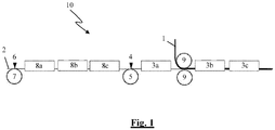
- the device (10) shown in fig. 1 for the application of a compact polyurethane coating to a flexible support material (1) comprises a coating blade located above a coating roller (5) as a coating head (4) for the application of a mixture comprising polyurethane components to a transfer substrate (2).
- a transfer substrate (2) any mixture with a pot life (open time) of more than 10 minutes is suitable for this.
- the pot life may be less if the rotation speed is increased.
- a transfer substrate (2) was used.
- a transfer substrate (2) one may select e.g. PET film. This transfer substrate (2) is fed in by means of a feeding device, which is not shown.
- this can initially be rolled onto a roller, rolled off said roller and fed through and over rollers to the parts of the device (10) shown. It is also possible to use e.g. a conveyor belt as the transfer substrate (2).
- the transfer substrate (2) is preferably fed at a rate of 5 to 12 m/min depending on the type of polyurethane. Even more preferably, a rate of between 10 and 12 m/min is selected. This rate is typically selected depending on the type of polyurethane and the amount to be produced.
- an oven (3a) is configured to heat the transfer substrate (2) with the mixture applied thereto in order to partially cure said mixture.
- the temperature to which the transfer substrate (2) with the mixture applied thereto is exposed should preferably be between 60°C and 100°C.
- the residence time in the oven depends on the reaction behaviour of the PU system and the heating source.
- the transfer substrate (2) with the mixture applied thereto is heated e.g. for about 3 minutes at 80°C.
- the description of the diagram in fig. 2 also indicates how best to determine the extent to which the mixture should be partially cured.
- a laminating device (9) is also configured, in this case comprising pressure rollers (9) by means of which the transfer substrate (2) is brought together with a flexible support material (1) fed from a feeding device which is not shown.
- This flexible support material (1) can e.g. initially be rolled onto a roller and then rolled off said roller and through and over rollers until it reaches the laminating device (9).
- Typical carrier materials (1) include knit fabrics, fabrics, glass fibres, non-wovens, breathable membranes, etc.
- the laminating device (9) several more ovens (3b, 3c) are configured with which the mixture is further cured. Further curing depends on the extent to which the mixture has already been cured. In this case, the mixture can be further cured e.g. for 2.5 to 6 min in an oven 25 to 30 m in length at a temperature between 60 and 100°C.
- a separating device which is not shown, is configured by means of which the transfer substrate (2) is separated from the flexible support material (1) with the compact polyurethane coating applied to it.
- an additional coating head (6) and additional ovens (8a, 8b, 8c) are configured by means of which an additional coating can be applied and cured prior to the polyurethane coating.
- the diagram in fig. 2 shows how one can determine the optimum extent to which the mixture is to be cured before applying it to the flexible support material.
- the system used for this test is the IMAPUR SF POL - IMAPUR SF ISO with INDEX 100.
- an MCR301 device from Anton Paar was equipped with a new disc-shaped disposable measuring head 25 mm in diameter.
- the null point of the rheometer was set.
- time 0 is therefore actually 180 s after the first contact between polyol and isocyanate.
- Measurement in the rheometer was conducted for 90 s at 18°C each second in a first measurement and at a second temperature every second (60°C or 120°C in the figure) in a second step.
- the heating rate was approximately 5.5°C/10s.
- the figure also shows the complex viscosity measured in Pa ⁇ s as a function of time in s.
- test step 2 has a clear effect on the length of the viscosity drop, but a much less pronounced effect on the extent of the viscosity drop. This point will vary over time depending on the temperature in test step 2. The same therefore applies to points z and z'. A more rapidly reacting system will show a similar figure, but point z will be shifted further to the left (first time period) at the same temperature in test step 2. The reverse holds true for a more slowly reacting system. Other factors include: speed and thoroughness of mixing, amount of energy supplied during mixing, selected mixture, presence of air bubbles in the sample, etc.
- the point of application of the mixture to the carrier material (the point of insertion of the fabric) is dependent within this range on the desired application, and is preferably selected such that:
- the properties discussed above depend on the material from which the carrier material is made (PES-CO, aramids, glass fibres, synthetic, natural, etc.), the weight of the material, the type of fibres used (roughened, monofilament, multifilament, etc.), possible pretreatment of the material (water-repellent, dirt-repellant, etc.), the production technology used, residue of products from the fabrication process, paints, etc.
- the figure shows what happens during the production process of a carrier material coated with a 2-component system.
- the object is, based on this figure, to adjust the production rate and the temperature of the first oven (between the blade and the insertion of the carrier material) in such a way that the optimum viscosity is achieved at the point of insertion (which is selected as a fixed point for reasons of convenience of production and robustness of the process).
- the point of insertion which is selected as a fixed point for reasons of convenience of production and robustness of the process.
- a top layer of 50g/m 2 is applied that is completely uncured.
- an adhesive layer of 50g/m 2 is applied on which the fabric is inserted.
- Various knit fabrics are coated in this manner, with the fabric being applied each time at a different viscosity:
- a top layer is applied of 50g/m 2 that is completely uncured.
- an adhesive layer of 50g/m 2 is applied to this layer.
- a top layer is applied of 50g/m 2 that is completely uncured.
- an adhesive layer of 50g/m 2 on which the fabric is inserted.
- Various PES fabrics are coated in this manner, with the fabric being applied each time at a different viscosity:
Landscapes
- Engineering & Computer Science (AREA)
- Textile Engineering (AREA)
- Chemical & Material Sciences (AREA)
- Chemical Kinetics & Catalysis (AREA)
- Dispersion Chemistry (AREA)
- Health & Medical Sciences (AREA)
- Toxicology (AREA)
- Application Of Or Painting With Fluid Materials (AREA)
- Laminated Bodies (AREA)
Description
- This invention concerns a method for the application of a compact polyurethane coating to a flexible support material, comprising the provision of a flexible support material, the application of a mixture comprising polyurethane components to this flexible support material.
- This invention specifically concerns such methods wherein the compact polyurethane coating is directly applied to the flexible support material, i.e., without first applying other coatings to this flexible support material.
In (chemical) curing of such a polyurethane coating, the components are polymerized. - There are currently various methods available for applying a compact polyurethane coating to a flexible support material. For example, there are solvent-based and water-based methods on the one hand and extrusion methods on the other with which polyurethane can be applied to the carrier material either directly or via a transfer substrate.
- Conventional methods use solvents in which polyurethane is dissolved in order to apply said solvents to the carrier material, after which the solvent is evaporated. Examples of such conventional methods are described in
GB 1101911 A WO 2013/041397 . These methods easily allow functional properties such as fire resistance, antistatic properties, antimicrobial properties, antiviral properties, etc. to be incorporated. Solvent-based methods make it possible to obtain such coatings with low tolerance in thickness. Good homogeneity can be achieved. The formulation process is simple and allows rapid changes in production to be carried out.
Drawbacks of solvent-type coatings include the ecological footprint resulting from residual pastes, volatile organic substances, etc., the high energy consumption of the coating process and the high investment cost. - Because of the increasingly stringent regulations on solvents, water-based methods are being applied to an increasing extent. In this case, an emulsion or a dispersion of polyurethane in water is applied to a carrier material and the water is evaporated off Originally, for this purpose, the polyurethane was first dissolved in a solvent, after which the solvent was replaced with water. In more recent methods, non-solvent-based dispersants are used to prepare an emulsion or dispersion of polyurethane in water, or the polyurethane is directly placed in an aqueous emulsion or dispersion.
Using these water-based methods, relatively thin coatings can also be applied with a relatively small tolerance in thickness. However, these methods do not allow coatings to be obtained which are of the same thickness as when solvents are used. These methods also allow relatively rapid production changes to be carried out.
However, water-based methods are much more expensive than solvent-based methods, are more difficult to formulate, and have an even higher energy cost for evaporating off the water. In addition to technical drawbacks, e.g. with respect to washing resistance, the possibilities for applying transfer coatings are limited because of a lack of suitable transfer paper and the fact that the few types of suitable transfer paper are particularly expensive. Combinations of particular properties, such as e.g. weldability and washing resistance, are problematic. - Extrusion is probably the most widely-used method of applying a polyurethane film. This method is completely solvent-free. In extrusion, granules or thermoplastic polymers such as thermoplastic polyurethane are melted in an extruder and transported to the coating system, which e.g. can be configured as a matrix or calendar, etc. The production process is rapid and relatively inexpensive.
However, among the drawbacks of this method are that it does not allow rapid changes in production (changing of the polymer, colour changes, cleaning cycle, etc.), a polyurethane film produced by this method has greater tolerances in thickness, and the coatings obtained may be thin. The possible formulations are limited, and the method can only be applied to thermoplastics. - In reactive extrusion, one can work with a combination of dissolution in solvent and extruding of pellets, which results in a combination of the advantages and drawbacks of both methods.
- In the automobile sector and for window coverings, artificial leather, floor coverings, shoe soles, etc. polyurethane is also applied in two components to a carrier material, with the reaction taking place on the spot after application of the components to the carrier material. However, the known processes are not suitable for the coating of textiles, because they require long curing times. Attempts to adapt these processes are already in progress, but problems have emerged, with the coating penetrating into or even through the flexible support material. This results in insufficient adhesion and/or poor surface quality and/or excessive stiffness of the product as a whole, etc.
- The object of this invention is therefore also to provide a workable solvent-free and non-water-based method for the application of a compact polyurethane coating to a flexible support material with which the same advantages can be achieved as with current solvent-based and water-based methods.
- This object of the invention is achieved by providing a method for the application of a compact polyurethane coating to a flexible support material comprising the provision of a flexible support material, the application of a mixture comprising polyurethane components to this flexible support material, wherein the mixture comprising polyurethane components is entirely free of solvents and water and at least a part of the mixture is partially polymerized before it is applied directly to the flexible support material and the mixture applied to the flexible support material is polymerized to obtain a compact polyurethane coating.
- By curing (polymerizing) at least a part of the mixture before it is applied to the flexible support material, the viscosity of the mixture comprising polyurethane components applied to the carrier material is increased, and this mixture does not penetrate as deeply into the flexible support material.
- The flexible support material can be a textile (fabric, knit fabric or non-woven) or paper, a breathable membrane, glass fibre, etc. If this flexible support material is a textile, it can be produced from polyester or cotton, aramids, combinations thereof, etc.
- The mixture comprising polyurethane components should normally comprise a polyol mixture, an isocyanate mixture, and optionally additives. In order to affect the process, these additives may include chain-lengthening agents, crosslinkers, levelling agents, release agents, antifoaming agents, etc. In order to impart desired properties to the end product, these additives may include antibacterial products, pigments that are reflective or emit an afterglow, fillers, density-reducing additives, etc. This mixture comprising polyurethane components is entirely free of solvents and water.
- In a preferred method according to this invention, a transfer substrate is provided to which the mixture is applied so that a partially cured mixture is obtained on the transfer substrate and the partially cured mixture is transferred from the transfer substrate to the flexible support material.
- At present, in coating of textiles, the coating is either applied to the flexible support material before it is cured (polymerized) or after it is cured (polymerized). The method of the present invention lies between these two approaches, with the coating being applied to the flexible support material in a partially cured (polymerized) state. This causes the coating to penetrate less deeply into the flexible support material than it would have if said material were not yet partially cured. In this case, the time of application of the coating to the flexible support material can be controlled depending on the type of carrier material used.
- Typical transfer paper may be selected as a transfer substrate. This may be a film which can be made e.g. from paper or metal or plastic. Such a transfer substrate is characterized in that it is suitable for the application of polyurethane components, with these components being at least partly curable to obtain a polyurethane coating, and the transfer substrate can then again be released from this polyurethane coating.
- This mixture comprising polyurethane components is preferably uniformly spread over the entire surface of the transfer substrate applied, which is subsequently brought into contact with the flexible support material in order to transfer the mixture to this flexible support material.
- Such a transfer substrate may be configured as a flat surface or may be provided with a textured surface.
- In such a method according to this invention, the mixture is preferably partially cured on the transfer substrate. More specifically, for this purpose, the transfer substrate can be exposed to an energy source in order to partially cure the mixture applied thereto.
- In exposure of the transfer substrate to an energy source, said substrate may be exposed e.g. to elevated temperature in e.g. an oven or on heated surfaces, to IR light, UV light, etc. or to other influences which can affect the curing of the mixture comprising polyurethane components.
- In a particularly preferred variant of such a method according to this invention, the partially cured mixture is transferred from the transfer substrate to the flexible support material when the viscosity of the partially cured mixture has reached a level between 150% and 800% of the minimum viscosity of said partially cured mixture.
The lower this viscosity is when the mixture is applied to the flexible support material, the greater the penetration into the fabric and the greater the chance of breakthrough. When this value increases, penetration decreases, thus reducing the chance of breakthrough, but adhesion also decreases, thus reducing resistance to mechanical stress. - Among other factors, the choice of when to insert the carrier material within the aforementioned ranges depends on the following:
- Type of fabric: The density and absorbent properties of the flexible support material. With heavier and less absorbent fabrics, there is less risk of breakthrough, so the flexible support material should preferably be inserted when values are lower.
- Desired touch: The later the fabric is inserted, the more flexible the coated carrier material will feel, because less of the coating has penetrated it.
- Adhesion: If the carrier material is inserted at lower viscosity, the adhesion, and therefore also the washing performance, will generally be better than when it is inserted at higher viscosity.
- Preferably, the partially cured mixture is not transferred to the flexible carrier until the viscosity is between 150% and 500% of the minimum viscosity, and even more preferably between 150% and 300% of the minimum viscosity.
- For this purpose, this viscosity can be determined using the MCR301 device from Anton Paar. The viscosity is determined by means of oscillating critical shear stress. This test is typically used for cured resins.
In order to determine viscosity using the device, the sample to be measured is inserted between the measuring head and the scale. The measuring head is allowed to move at an angular velocity of 10 rad/s. In this case, the measuring head causes a certain deformation of the sample. The force required for this is used in order to calculate complex viscosity. - Furthermore, the flexible support material is preferably exposed to an energy source in order to cure the mixture applied thereto. With respect to this exposure to an energy source, the material can be exposed e.g. to elevated temperature in e.g. an oven, to IR light, or to other influences which can affect curing of the mixture comprising polyurethane components.
- A device with which an above-mentioned method according to this invention can be applied can be a device for the application of a compact polyurethane coating to a flexible support material, comprising:
- a substrate feeding device for the feeding of a transfer substrate;
- a coating head for the application of a mixture comprising polyurethane components to the transfer substrate;
- a carrier material feeding device for the feeding of a flexible support material;
- a laminating device for bringing together the fed transfer substrate with the mixture applied thereto and the fed flexible support material before transferring the mixture from the transfer substrate to the flexible support material;
- an energy source for exposure of the transfer substrate and flexible support material brought together with the laminating device to energy for polymerization of the mixture applied thereto;
- Wherein the carrier material feeding device is provided in order to bring the flexible support material directly to the laminating device and wherein said device comprises an additional energy source for exposing the mixture applied to the transfer substrate to energy for partially curing the mixture applied thereto, which energy source is configured between the coating head and the laminating device, such that the transfer substrate is brought directly from this energy source to the laminating device.
- By means of this energy source, which is configured between the coating head and the laminating device, a mixture applied to the transfer substrate using the coating head can be partially polymerized before the transfer substrate and the flexible support material are brought together using the laminating device, so that the mixture is partially polymerized before being applied to the flexible support material. The mixture comprising polyurethane components therefore penetrates less deeply into the flexible support material when it is transferred to said flexible support material.
- In this case, the carrier material feeding device is preferably provided in order to bring the flexible support material directly to the laminating device, i.e., without said flexible support material first being subjected to other treatments.
The energy source to which the mixture applied to the transfer substrate is exposed is preferably configured in the device in such a manner that the transfer substrate is brought directly from this energy to the laminating device,, i.e. without being subjected to other treatments in the meantime. - A special device can comprise an additional coating head which is configured in order to apply an additional coating to the transfer substrate before application of the mixture by means of the first coating head to the transfer substrate and comprises an additional energy source configured between the additional coating head and the first coating head in order to at least partially cure this additional coating on the transfer substrate.
- Using this additional coating head, e.g. a top layer can be applied in order to impart additional properties to the flexible support material with the compact polyurethane coating applied to it, such as securing with a water column (HSH), touch, a printable surface, anti-slip properties, an adapted external appearance (flat, shiny, coloured, relief...), scratch resistance, antibacterial properties, etc.
This additional coating can be at least partially cured using this additional energy source and then further cured together with the compact polyurethane coating or can be completely cured before the mixture comprising polyurethane components is applied to it. - In addition to the aforementioned coating heads and the aforementioned energy sources, a device can also be provided with further coating heads and/or further energy sources.
- At least one of the aforementioned energy sources of a said device is preferably configured as an oven or an IR field. Alternatively, but less preferably, heated plates could also be used as an energy source, or UV lamps, etc.
- The aforementioned coating heads can be configured as brushing heads with which paste is applied for a blade. In this case, the paste may be poured or pumped for this blade. Alternatively, these coating heads could also be configured as e.g. castings and/or as spray heads, etc.
- Preferably, a device can comprise a separating device for separating the transfer substrate from the flexible support material with the mixture transferred thereto.
- The compact polyurethane coating can be completely cured before the transfer substrate of the flexible support material is separated. However, it is also possible to allow the compact polyurethane coating to cure further after the transfer substrate has been separated from the flexible support material.
- This invention is now explained further by means of the following detailed description of several preferred methods according to this invention. This description is exclusively intended to give examples and indicate further advantages and special characteristics of this invention, and therefore cannot be construed as a limitation of the scope of application of the invention or the patent rights arising from the claims.
- In this detailed description, reference is made to the attached drawings by means of reference numbers, in which:
-
Fig. 1 is a schematic diagram of a part of a device; -
Fig. 2 shows the complex viscosity of a mixture as a function of time. - The device (10) shown in
fig. 1 for the application of a compact polyurethane coating to a flexible support material (1) comprises a coating blade located above a coating roller (5) as a coating head (4) for the application of a mixture comprising polyurethane components to a transfer substrate (2). Generally, when working with a transfer substrate (2), any mixture with a pot life (open time) of more than 10 minutes is suitable for this. When the mixture is directly applied to the carrier material (1), the pot life may be less if the rotation speed is increased. In the devices shown, a transfer substrate (2) was used.
As a transfer substrate (2), one may select e.g. PET film.
This transfer substrate (2) is fed in by means of a feeding device, which is not shown. For example, this can initially be rolled onto a roller, rolled off said roller and fed through and over rollers to the parts of the device (10) shown. It is also possible to use e.g. a conveyor belt as the transfer substrate (2).
The transfer substrate (2) is preferably fed at a rate of 5 to 12 m/min depending on the type of polyurethane. Even more preferably, a rate of between 10 and 12 m/min is selected. This rate is typically selected depending on the type of polyurethane and the amount to be produced.
After said coating head (4), an oven (3a) is configured to heat the transfer substrate (2) with the mixture applied thereto in order to partially cure said mixture. The temperature to which the transfer substrate (2) with the mixture applied thereto is exposed should preferably be between 60°C and 100°C. The residence time in the oven depends on the reaction behaviour of the PU system and the heating source. In this case, the transfer substrate (2) with the mixture applied thereto is heated e.g. for about 3 minutes at 80°C.
The description of the diagram infig. 2 also indicates how best to determine the extent to which the mixture should be partially cured.
After the oven (3a), a laminating device (9) is also configured, in this case comprising pressure rollers (9) by means of which the transfer substrate (2) is brought together with a flexible support material (1) fed from a feeding device which is not shown. This flexible support material (1) can e.g. initially be rolled onto a roller and then rolled off said roller and through and over rollers until it reaches the laminating device (9). Typical carrier materials (1) include knit fabrics, fabrics, glass fibres, non-wovens, breathable membranes, etc.
After the laminating device (9), several more ovens (3b, 3c) are configured with which the mixture is further cured. Further curing depends on the extent to which the mixture has already been cured. In this case, the mixture can be further cured e.g. for 2.5 to 6 min in an oven 25 to 30 m in length at a temperature between 60 and 100°C.
After this, a separating device, which is not shown, is configured by means of which the transfer substrate (2) is separated from the flexible support material (1) with the compact polyurethane coating applied to it. - In the device (10) as shown in
fig. 1 , prior to the above-mentioned coating head (4), an additional coating head (6) and additional ovens (8a, 8b, 8c) are configured by means of which an additional coating can be applied and cured prior to the polyurethane coating. - The diagram in
fig. 2 shows how one can determine the optimum extent to which the mixture is to be cured before applying it to the flexible support material. The system used for this test is the IMAPUR SF POL - IMAPUR SF ISO withINDEX 100. - In order to produce this figure, an MCR301 device from Anton Paar was equipped with a new disc-shaped disposable measuring head 25 mm in diameter. The null point of the rheometer was set.
- 5 g of polyol was weighed using a 5 ml plastic syringe. In order to prepare a sample and load the device, the following steps were taken within 3 min:
- Addition of isocyanate (8.37)/2 g using a 5 ml plastic syringe. Said 3-min period started with the first contact between polyol and isocyanate. Thickening of the isocyanate was prevented to the extent possible by taking the isocyanate from deeper layers of the recipient.
- Mixing of polyol and isocyanate using a spatula, avoiding air inclusions to the extent possible.
- Insertion of the sample in the device.
- Sealing of the rheometer with a clearance of 0.5 mm. If the clearance is less, the measuring sample has too great an effect on the measurements.
- Removal of excess sample so that only sample material having a diameter of 25 mm was present under the disc-shaped measuring head.
- Closing of the oven of the device.
- After the aforementioned 3-min period had expired, measurement in the rheometer was begun.
- This is also the point at which the process shown in the figure started. In the figure, time 0 is therefore actually 180 s after the first contact between polyol and isocyanate. Measurement in the rheometer was conducted for 90 s at 18°C each second in a first measurement and at a second temperature every second (60°C or 120°C in the figure) in a second step. The heating rate was approximately 5.5°C/10s.
- The figure also shows the complex viscosity measured in Pa·s as a function of time in s.
- This figure is the same in form for each polyurethane 2-component system, but the various points (x, y, z, z' A, B) may fall within another time period at the same temperature.
- The various points and zones in the figure are as follows:
- Point x: start of measurement 180 seconds after the first contact between polyol and isocyanate.
- Point y: end of the first temperature plateau after 90 seconds. From this point on, the second measurement step begins. This is followed by an increase in temperature to 60°C and 120°C respectively.
- Zone between point x and point y: steady reaction at room temperature. In the measuring process used, this is 18°C. This reaction increases the mean molecular weight. In other words, larger molecules are formed. Larger molecules show higher viscosity, which is clearly visible in the figure. The more rapidly the system reacts, the more rapidly the figure in this zone will increase. Other factors include: speed and thoroughness of mixing, amount of energy supplied during mixing, mixture selected presence of air bubbles in the sample, etc.
- Point z: the point of minimum viscosity at 120°C in
step 2 of the measuring process. - Point z': the point of minimum viscosity at 60°C in
step 2 of the measuring process. - Zone between point y and point z or z': decreasing viscosity. This is referred to as a viscosity drop. Temperature increases in this zone. As is the case for the majority of liquids (the polyol/isocyanate mixture is still liquid because it has not yet fully reacted), viscosity drops with increasing temperature. At the same time, reactivity increases as a result of the rising temperature. The further course and acceleration of the reaction will cause the velocity to increase. Point z or z' marks the point at which the decreasing viscosity resulting from the increasing temperature is compensated for by the increasing viscosity resulting from the further course of the reaction. Beyond this point, the further course of the reaction exceeds the increase in temperature. The result is increasing viscosity from this point on.
- It is also clear here that the temperature of
test step 2 has a clear effect on the length of the viscosity drop, but a much less pronounced effect on the extent of the viscosity drop. This point will vary over time depending on the temperature intest step 2. The same therefore applies to points z and z'. A more rapidly reacting system will show a similar figure, but point z will be shifted further to the left (first time period) at the same temperature intest step 2. The reverse holds true for a more slowly reacting system. Other factors include: speed and thoroughness of mixing, amount of energy supplied during mixing, selected mixture, presence of air bubbles in the sample, etc. - Point A: minimum viscosity at which the mixture can preferably be applied to a carrier material according to the present invention. For the various curves, this point lies at a viscosity of approximately 150% of the minimum viscosity (z, z').
- Point B: maximum viscosity at which the mixture can preferably be applied to a carrier material according to the present invention. For the various curves, this point lies at a viscosity of approximately 800% of the minimum viscosity (z, z').
- Zone between point A and point B: viscosity range within which the mixture can preferably be applied to a carrier material according to the present invention, this is between 150% and 800% of the minimum viscosity (z, z').
- The point of application of the mixture to the carrier material (the point of insertion of the fabric) is dependent within this range on the desired application, and is preferably selected such that:
- The viscosity reached is already high enough to prevent the carrier material from absorbing too much of the reacting mixture. Should this be the case, this will result in a carrier material having a harder feel.
- The viscosity reached is still low enough for a part of the reacting mixture to penetrate into the carrier material in order to chiefly provide mechanical adhesion. The part of the mixture that does not penetrate the carrier material provides adhesion to the optional first coating layer or forms the closed coating layer on the carrier material.
- Use of pressure in the application of the mixture to the carrier material makes it possible within the viscosity range at which insertion can be carried out with the desired result to be both increased and somewhat lowered. The pressure exerted helps to improve penetration of the carrier material, while the minimum viscosity simultaneously increases. This results in a more robust process that is less sensitive to external factors. However, exerting pressure during insertion is not required, and in a number of cases it may even be undesirable.
- In practice, this means that:
- Heavier, more closed, less absorbent carrier material should preferably be inserted closer to point A than point B.
- Lighter, more open, more absorbent carrier material should preferably be inserted closer to point B than point A.
- The properties discussed above depend on the material from which the carrier material is made (PES-CO, aramids, glass fibres, synthetic, natural, etc.), the weight of the material, the type of fibres used (roughened, monofilament, multifilament, etc.), possible pretreatment of the material (water-repellent, dirt-repellant, etc.), the production technology used, residue of products from the fabrication process, paints, etc.
- The figure shows what happens during the production process of a carrier material coated with a 2-component system. The object is, based on this figure, to adjust the production rate and the temperature of the first oven (between the blade and the insertion of the carrier material) in such a way that the optimum viscosity is achieved at the point of insertion (which is selected as a fixed point for reasons of convenience of production and robustness of the process). In practice, there are therefore several possible combinations of speed, pre-curing temperature and pressure in order to achieve an optimum result.
- As this method reflects complex viscosity (or critical shear stress-based viscosity), the elapsed time should naturally be determined according to the production process. It is easy for a person having average skill in the art to make this determination based on the limited number of systems used as a standard line. The exact construction of the industrial line, the type and capacity of heating selected, etc., will strongly affect this reaction.
- In the first example, a top layer of 50g/m2 is applied that is completely uncured. One then applies to this layer an adhesive layer of 50g/m2, on which the fabric is inserted. Various knit fabrics are coated in this manner, with the fabric being applied each time at a different viscosity:
- At 200% of the minimum viscosity:
- Pre-curing for 3 minutes at 60°C before insertion of the fabric.
- Measured adhesion: 7N/2.2 cm.
- At 257% of the minimum viscosity:
- Pre-curing for 3 minutes at 80°C before insertion of the fabric.
- Measured adhesion: 30N/2.2 cm.
- At 275% of the minimum viscosity:
- Pre-curing for 3 minutes at 100°C before insertion of the fabric.
- Measured adhesion: 9N/2.2 cm.
- At 290% of the minimum viscosity:
- Pre-curing for 3 minutes at 120°C before insertion of the fabric.
- Measured adhesion: 6N/2.2 cm.
- In the first example, a top layer is applied of 50g/m2 that is completely uncured. One then applies to this layer an adhesive layer of 50g/m2, on which the fabric is inserted.
- Various cotton fabrics are coated in this manner, with the fabric being applied each time at a different viscosity:
- At 200% of the minimum viscosity:
- Pre-curing for 3 minutes at 60°C before insertion of the fabric.
- Measured adhesion: 7N/2.2 cm.
- At 257% of the minimum viscosity:
- Pre-curing for 3 minutes at 80°C before insertion of the fabric.
- Measured adhesion: 50N/2.2 cm.
- At 275% of the minimum viscosity:
- Pre-curing for 3 minutes at 100°C before insertion of the fabric.
- Measured adhesion: 20N/2.2 cm.
- In the first example, a top layer is applied of 50g/m2 that is completely uncured. One then applies to this layer an adhesive layer of 50g/m2, on which the fabric is inserted. Various PES fabrics are coated in this manner, with the fabric being applied each time at a different viscosity:
- At 200% of the minimum viscosity:
- Pre-curing for 3 minutes at 60°C before insertion of the fabric.
- Measured adhesion: 4N/2.2 cm.
- At 257% of the minimum viscosity:
- Pre-curing for 3 minutes at 80°C before insertion of the fabric.
- Measured adhesion: 35N/2.2 cm.
- At 275% of the minimum viscosity:
- Pre-curing for 3 minutes at 100°C before insertion of the fabric.
- Measured adhesion: 35N/2.2 cm.
- At 290% of the minimum viscosity:
- Pre-curing for 3 minutes at 120°C before insertion of the fabric.
- Measured adhesion: 20N/2.2 cm.
Claims (6)
- Method for the application of a compact polyurethane coating to a flexible support material (1), comprising the provision of a flexible support material (1), the application of a mixture comprising polyurethane components to this flexible support material (1) characterized in that the mixture comprising polyurethane components is entirely free of solvents and water and at least a part of the mixture is partially polymerized before it is applied directly to the flexible support material (1) and the mixture applied to the flexible support material (1) is polymerized to obtain a compact polyurethane coating.
- Method according to claim 1, characterized in that a transfer substrate (2) is provided to which the mixture is applied, so that a partially cured mixture is obtained on the transfer substrate (2), and in that the partially cured mixture is transferred from the transfer substrate (2) to the flexible support material (1).
- Method according to claim 2, characterized in that the mixture is partially cured on the transfer substrate (2).
- Method according to claim 3, characterized in that the transfer substrate (2) is exposed to an energy source (3a) in order to partially cure the mixture applied thereto.
- Method according to one of claims 2 to 4, characterized in that the partially cured mixture is transferred from the transfer substrate (2) to the flexible support material (1) when the viscosity of the partially cured mixture is between 150% and 800% of the minimum viscosity reached by said partially cured mixture, preferably between 150% and 500%, and even more preferably between 150% and the 300%.
- Method according to one of the previous claims, characterized in that the flexible support material (1) is exposed to an energy source (3b, 3c) in order to cure the mixture applied thereto.
Applications Claiming Priority (1)
| Application Number | Priority Date | Filing Date | Title |
|---|---|---|---|
| BE20155104A BE1023124A9 (en) | 2015-02-26 | 2015-02-26 | Method and device for applying a compact polyurethane coating on a flexible carrier material |
Publications (2)
| Publication Number | Publication Date |
|---|---|
| EP3061532A1 EP3061532A1 (en) | 2016-08-31 |
| EP3061532B1 true EP3061532B1 (en) | 2019-12-04 |
Family
ID=53432905
Family Applications (1)
| Application Number | Title | Priority Date | Filing Date |
|---|---|---|---|
| EP16157241.7A Revoked EP3061532B1 (en) | 2015-02-26 | 2016-02-25 | Method for the transfer of a partially cured polyurethan coating to a flexible support |
Country Status (2)
| Country | Link |
|---|---|
| EP (1) | EP3061532B1 (en) |
| BE (1) | BE1023124A9 (en) |
Families Citing this family (1)
| Publication number | Priority date | Publication date | Assignee | Title |
|---|---|---|---|---|
| US20180345625A1 (en) * | 2017-05-31 | 2018-12-06 | Vetex Nv | Marking element |
Citations (11)
| Publication number | Priority date | Publication date | Assignee | Title |
|---|---|---|---|---|
| US3330713A (en) | 1962-01-30 | 1967-07-11 | Dunlop Rubber Co | Method of coating textile fabrics |
| GB1101911A (en) | 1964-07-21 | 1968-02-07 | Ici Ltd | Method of forming a patterned surface sheet material |
| DE1923871A1 (en) | 1968-05-09 | 1970-07-02 | Atlantic Gummed Paper Corp | Process for the production of polyurethane films or laminates |
| US3575754A (en) | 1962-01-31 | 1971-04-20 | Ici Ltd | Manufacture of thermoplastic sheet material |
| DE2352626A1 (en) | 1972-10-20 | 1974-04-25 | Atlantic Richfield Co | METHOD OF MANUFACTURING FABRICS INCLUDING A POLYURETHANE COVER |
| DD235469A1 (en) | 1985-03-15 | 1986-05-07 | Adw Ddr | METHOD FOR THE PRODUCTION OF SOFT BREATHABLE ARTIFICIAL LEATHER |
| DD254403A1 (en) | 1986-12-05 | 1988-02-24 | Akad Wissenschaften Ddr | POLYURETHANE COATING FOR THE SURFACE FINISHING OF WOVEN FABRICS, GEARS, FLEECES OR LEATHER AFTER THE REVERSE COATING PROCESS |
| BE1013333A3 (en) | 2000-02-29 | 2001-12-04 | Vetex Nv | Method for coating a flexible substrate by means of a thermoplasticpolyurethane coating |
| WO2006097508A1 (en) | 2005-03-17 | 2006-09-21 | Basf Aktiengesellschaft | Method for producing polyurethane layers and use thereof as imitation leather |
| WO2013040765A1 (en) | 2011-09-21 | 2013-03-28 | Basf Se | Artificial leather with improved flexing endurance properties |
| WO2015110953A1 (en) | 2014-01-23 | 2015-07-30 | Giacomino Adolfo Agosti | Method for making a product of the type comprising a laminar supporting element and an upgrading layer and corresponding system. |
-
2015
- 2015-02-26 BE BE20155104A patent/BE1023124A9/en active
-
2016
- 2016-02-25 EP EP16157241.7A patent/EP3061532B1/en not_active Revoked
Patent Citations (16)
| Publication number | Priority date | Publication date | Assignee | Title |
|---|---|---|---|---|
| US3330713A (en) | 1962-01-30 | 1967-07-11 | Dunlop Rubber Co | Method of coating textile fabrics |
| US3575754A (en) | 1962-01-31 | 1971-04-20 | Ici Ltd | Manufacture of thermoplastic sheet material |
| GB1101911A (en) | 1964-07-21 | 1968-02-07 | Ici Ltd | Method of forming a patterned surface sheet material |
| DE1923871A1 (en) | 1968-05-09 | 1970-07-02 | Atlantic Gummed Paper Corp | Process for the production of polyurethane films or laminates |
| US3539424A (en) | 1968-05-09 | 1970-11-10 | Wharton Ind Inc | Polyurethane film and laminate thereof |
| DE2352626A1 (en) | 1972-10-20 | 1974-04-25 | Atlantic Richfield Co | METHOD OF MANUFACTURING FABRICS INCLUDING A POLYURETHANE COVER |
| US3844862A (en) | 1972-10-20 | 1974-10-29 | Atlantic Richfield Co | A method of coating fabrics with polyurethane |
| DD235469A1 (en) | 1985-03-15 | 1986-05-07 | Adw Ddr | METHOD FOR THE PRODUCTION OF SOFT BREATHABLE ARTIFICIAL LEATHER |
| DD254403A1 (en) | 1986-12-05 | 1988-02-24 | Akad Wissenschaften Ddr | POLYURETHANE COATING FOR THE SURFACE FINISHING OF WOVEN FABRICS, GEARS, FLEECES OR LEATHER AFTER THE REVERSE COATING PROCESS |
| BE1013333A3 (en) | 2000-02-29 | 2001-12-04 | Vetex Nv | Method for coating a flexible substrate by means of a thermoplasticpolyurethane coating |
| WO2006097508A1 (en) | 2005-03-17 | 2006-09-21 | Basf Aktiengesellschaft | Method for producing polyurethane layers and use thereof as imitation leather |
| EP1861251B2 (en) | 2005-03-17 | 2012-06-13 | Basf Se | Method for producing polyurethane layers and use thereof as imitation leather |
| WO2013040765A1 (en) | 2011-09-21 | 2013-03-28 | Basf Se | Artificial leather with improved flexing endurance properties |
| WO2013041397A1 (en) * | 2011-09-21 | 2013-03-28 | Basf Se | Artificial leather with improved flexing endurance properties |
| US20140215850A1 (en) * | 2011-09-21 | 2014-08-07 | Basf Se | Artificial leather with improved flexing endurance properties |
| WO2015110953A1 (en) | 2014-01-23 | 2015-07-30 | Giacomino Adolfo Agosti | Method for making a product of the type comprising a laminar supporting element and an upgrading layer and corresponding system. |
Also Published As
| Publication number | Publication date |
|---|---|
| BE1023124A9 (en) | 2017-02-02 |
| BE1023124B1 (en) | 2016-11-25 |
| EP3061532A1 (en) | 2016-08-31 |
| BE1023124A1 (en) | 2016-11-25 |
Similar Documents
| Publication | Publication Date | Title |
|---|---|---|
| CN104769071B (en) | Sizing composition provides the purposes of bonding in wet environment | |
| EP2371881B1 (en) | Methods for polymerizing films in-situ using a radiation source | |
| AU2003277661B2 (en) | Retroreflective Sheet | |
| TW201510150A (en) | Reactive two-component adhesive system in film form | |
| CA2916981A1 (en) | Paint replacement film with polymer layer containing polyurethane | |
| Shim | Bonding requirements in coating and laminating of textiles | |
| TW201946768A (en) | Surface modification sheet, surface modification member, coated article and method for producing coated article | |
| TW201741422A (en) | Composition for preparing pressure-sensitive adhesives | |
| JP2016503440A (en) | Use of aqueous polyurethane dispersions for bonding molded products | |
| DE69925950T2 (en) | Method of tackifying the surface of a soft film | |
| EP3061532B1 (en) | Method for the transfer of a partially cured polyurethan coating to a flexible support | |
| EP3248767B1 (en) | Method for pre-preg manufacturing | |
| KR20180001065A (en) | Complex rubber sheet having a rubber sheet layer and a thermoplastic synthetic resin layer, and process for producing the same | |
| WO2011073262A1 (en) | Method of producing a self-adhesive surface on a wall or floor covering and a wall or floor covering | |
| JP6613017B2 (en) | Laminate, wood board, decorative board, and method for producing laminate | |
| WO2012017235A1 (en) | Covered floors and methods of adhering flooring to a floor | |
| KR20200026463A (en) | Thermal-reactive adhesive film for adhesion process of recycling upper leathers | |
| TWI565594B (en) | Foil bonding method | |
| US10889072B2 (en) | Method for pre-preg manufacturing | |
| JPH01294723A (en) | Thermosetting sheet for coating | |
| EP3755753A2 (en) | Method for producing articles coated with adhesive | |
| US20200056071A1 (en) | Vapour barrier, which is self-adhesive on one side, for sealing off floors having residual moisture | |
| KR100735458B1 (en) | Adhesive composition containing methyl acetate as a solvent | |
| DE1904986A1 (en) | Nonslip floor coating | |
| JPH01247142A (en) | Preparation of cover material |
Legal Events
| Date | Code | Title | Description |
|---|---|---|---|
| PUAI | Public reference made under article 153(3) epc to a published international application that has entered the european phase |
Free format text: ORIGINAL CODE: 0009012 |
|
| AK | Designated contracting states |
Kind code of ref document: A1 Designated state(s): AL AT BE BG CH CY CZ DE DK EE ES FI FR GB GR HR HU IE IS IT LI LT LU LV MC MK MT NL NO PL PT RO RS SE SI SK SM TR |
|
| AX | Request for extension of the european patent |
Extension state: BA ME |
|
| STAA | Information on the status of an ep patent application or granted ep patent |
Free format text: STATUS: REQUEST FOR EXAMINATION WAS MADE |
|
| 17P | Request for examination filed |
Effective date: 20170131 |
|
| RBV | Designated contracting states (corrected) |
Designated state(s): AL AT BE BG CH CY CZ DE DK EE ES FI FR GB GR HR HU IE IS IT LI LT LU LV MC MK MT NL NO PL PT RO RS SE SI SK SM TR |
|
| TPAC | Observations filed by third parties |
Free format text: ORIGINAL CODE: EPIDOSNTIPA |
|
| TPAC | Observations filed by third parties |
Free format text: ORIGINAL CODE: EPIDOSNTIPA |
|
| STAA | Information on the status of an ep patent application or granted ep patent |
Free format text: STATUS: EXAMINATION IS IN PROGRESS |
|
| 17Q | First examination report despatched |
Effective date: 20171124 |
|
| GRAP | Despatch of communication of intention to grant a patent |
Free format text: ORIGINAL CODE: EPIDOSNIGR1 |
|
| STAA | Information on the status of an ep patent application or granted ep patent |
Free format text: STATUS: GRANT OF PATENT IS INTENDED |
|
| RIC1 | Information provided on ipc code assigned before grant |
Ipc: B05D 3/02 20060101ALN20190607BHEP Ipc: B05D 1/28 20060101AFI20190607BHEP |
|
| INTG | Intention to grant announced |
Effective date: 20190712 |
|
| GRAS | Grant fee paid |
Free format text: ORIGINAL CODE: EPIDOSNIGR3 |
|
| GRAA | (expected) grant |
Free format text: ORIGINAL CODE: 0009210 |
|
| STAA | Information on the status of an ep patent application or granted ep patent |
Free format text: STATUS: THE PATENT HAS BEEN GRANTED |
|
| AK | Designated contracting states |
Kind code of ref document: B1 Designated state(s): AL AT BE BG CH CY CZ DE DK EE ES FI FR GB GR HR HU IE IS IT LI LT LU LV MC MK MT NL NO PL PT RO RS SE SI SK SM TR |
|
| REG | Reference to a national code |
Ref country code: GB Ref legal event code: FG4D |
|
| REG | Reference to a national code |
Ref country code: CH Ref legal event code: EP |
|
| REG | Reference to a national code |
Ref country code: AT Ref legal event code: REF Ref document number: 1208730 Country of ref document: AT Kind code of ref document: T Effective date: 20191215 |
|
| REG | Reference to a national code |
Ref country code: DE Ref legal event code: R096 Ref document number: 602016025345 Country of ref document: DE |
|
| REG | Reference to a national code |
Ref country code: IE Ref legal event code: FG4D |
|
| REG | Reference to a national code |
Ref country code: NL Ref legal event code: FP |
|
| REG | Reference to a national code |
Ref country code: LT Ref legal event code: MG4D |
|
| PG25 | Lapsed in a contracting state [announced via postgrant information from national office to epo] |
Ref country code: FI Free format text: LAPSE BECAUSE OF FAILURE TO SUBMIT A TRANSLATION OF THE DESCRIPTION OR TO PAY THE FEE WITHIN THE PRESCRIBED TIME-LIMIT Effective date: 20191204 Ref country code: BG Free format text: LAPSE BECAUSE OF FAILURE TO SUBMIT A TRANSLATION OF THE DESCRIPTION OR TO PAY THE FEE WITHIN THE PRESCRIBED TIME-LIMIT Effective date: 20200304 Ref country code: SE Free format text: LAPSE BECAUSE OF FAILURE TO SUBMIT A TRANSLATION OF THE DESCRIPTION OR TO PAY THE FEE WITHIN THE PRESCRIBED TIME-LIMIT Effective date: 20191204 Ref country code: LV Free format text: LAPSE BECAUSE OF FAILURE TO SUBMIT A TRANSLATION OF THE DESCRIPTION OR TO PAY THE FEE WITHIN THE PRESCRIBED TIME-LIMIT Effective date: 20191204 Ref country code: NO Free format text: LAPSE BECAUSE OF FAILURE TO SUBMIT A TRANSLATION OF THE DESCRIPTION OR TO PAY THE FEE WITHIN THE PRESCRIBED TIME-LIMIT Effective date: 20200304 Ref country code: GR Free format text: LAPSE BECAUSE OF FAILURE TO SUBMIT A TRANSLATION OF THE DESCRIPTION OR TO PAY THE FEE WITHIN THE PRESCRIBED TIME-LIMIT Effective date: 20200305 Ref country code: LT Free format text: LAPSE BECAUSE OF FAILURE TO SUBMIT A TRANSLATION OF THE DESCRIPTION OR TO PAY THE FEE WITHIN THE PRESCRIBED TIME-LIMIT Effective date: 20191204 |
|
| PGFP | Annual fee paid to national office [announced via postgrant information from national office to epo] |
Ref country code: NL Payment date: 20200219 Year of fee payment: 5 Ref country code: IT Payment date: 20200227 Year of fee payment: 5 Ref country code: DE Payment date: 20200219 Year of fee payment: 5 |
|
| PG25 | Lapsed in a contracting state [announced via postgrant information from national office to epo] |
Ref country code: HR Free format text: LAPSE BECAUSE OF FAILURE TO SUBMIT A TRANSLATION OF THE DESCRIPTION OR TO PAY THE FEE WITHIN THE PRESCRIBED TIME-LIMIT Effective date: 20191204 Ref country code: RS Free format text: LAPSE BECAUSE OF FAILURE TO SUBMIT A TRANSLATION OF THE DESCRIPTION OR TO PAY THE FEE WITHIN THE PRESCRIBED TIME-LIMIT Effective date: 20191204 |
|
| PGFP | Annual fee paid to national office [announced via postgrant information from national office to epo] |
Ref country code: BE Payment date: 20200219 Year of fee payment: 5 |
|
| PG25 | Lapsed in a contracting state [announced via postgrant information from national office to epo] |
Ref country code: AL Free format text: LAPSE BECAUSE OF FAILURE TO SUBMIT A TRANSLATION OF THE DESCRIPTION OR TO PAY THE FEE WITHIN THE PRESCRIBED TIME-LIMIT Effective date: 20191204 |
|
| PGFP | Annual fee paid to national office [announced via postgrant information from national office to epo] |
Ref country code: TR Payment date: 20200221 Year of fee payment: 5 Ref country code: FR Payment date: 20200219 Year of fee payment: 5 |
|
| PG25 | Lapsed in a contracting state [announced via postgrant information from national office to epo] |
Ref country code: CZ Free format text: LAPSE BECAUSE OF FAILURE TO SUBMIT A TRANSLATION OF THE DESCRIPTION OR TO PAY THE FEE WITHIN THE PRESCRIBED TIME-LIMIT Effective date: 20191204 Ref country code: RO Free format text: LAPSE BECAUSE OF FAILURE TO SUBMIT A TRANSLATION OF THE DESCRIPTION OR TO PAY THE FEE WITHIN THE PRESCRIBED TIME-LIMIT Effective date: 20191204 Ref country code: PT Free format text: LAPSE BECAUSE OF FAILURE TO SUBMIT A TRANSLATION OF THE DESCRIPTION OR TO PAY THE FEE WITHIN THE PRESCRIBED TIME-LIMIT Effective date: 20200429 Ref country code: ES Free format text: LAPSE BECAUSE OF FAILURE TO SUBMIT A TRANSLATION OF THE DESCRIPTION OR TO PAY THE FEE WITHIN THE PRESCRIBED TIME-LIMIT Effective date: 20191204 Ref country code: EE Free format text: LAPSE BECAUSE OF FAILURE TO SUBMIT A TRANSLATION OF THE DESCRIPTION OR TO PAY THE FEE WITHIN THE PRESCRIBED TIME-LIMIT Effective date: 20191204 |
|
| PG25 | Lapsed in a contracting state [announced via postgrant information from national office to epo] |
Ref country code: SK Free format text: LAPSE BECAUSE OF FAILURE TO SUBMIT A TRANSLATION OF THE DESCRIPTION OR TO PAY THE FEE WITHIN THE PRESCRIBED TIME-LIMIT Effective date: 20191204 Ref country code: IS Free format text: LAPSE BECAUSE OF FAILURE TO SUBMIT A TRANSLATION OF THE DESCRIPTION OR TO PAY THE FEE WITHIN THE PRESCRIBED TIME-LIMIT Effective date: 20200404 Ref country code: SM Free format text: LAPSE BECAUSE OF FAILURE TO SUBMIT A TRANSLATION OF THE DESCRIPTION OR TO PAY THE FEE WITHIN THE PRESCRIBED TIME-LIMIT Effective date: 20191204 |
|
| REG | Reference to a national code |
Ref country code: DE Ref legal event code: R026 Ref document number: 602016025345 Country of ref document: DE |
|
| PLBI | Opposition filed |
Free format text: ORIGINAL CODE: 0009260 |
|
| REG | Reference to a national code |
Ref country code: AT Ref legal event code: MK05 Ref document number: 1208730 Country of ref document: AT Kind code of ref document: T Effective date: 20191204 |
|
| PLAX | Notice of opposition and request to file observation + time limit sent |
Free format text: ORIGINAL CODE: EPIDOSNOBS2 |
|
| REG | Reference to a national code |
Ref country code: CH Ref legal event code: PL |
|
| 26 | Opposition filed |
Opponent name: FORBO SIEGLING GMBH Effective date: 20200903 Opponent name: BASF SE Effective date: 20200831 |
|
| PG25 | Lapsed in a contracting state [announced via postgrant information from national office to epo] |
Ref country code: LU Free format text: LAPSE BECAUSE OF NON-PAYMENT OF DUE FEES Effective date: 20200225 Ref country code: DK Free format text: LAPSE BECAUSE OF FAILURE TO SUBMIT A TRANSLATION OF THE DESCRIPTION OR TO PAY THE FEE WITHIN THE PRESCRIBED TIME-LIMIT Effective date: 20191204 Ref country code: MC Free format text: LAPSE BECAUSE OF FAILURE TO SUBMIT A TRANSLATION OF THE DESCRIPTION OR TO PAY THE FEE WITHIN THE PRESCRIBED TIME-LIMIT Effective date: 20191204 |
|
| PG25 | Lapsed in a contracting state [announced via postgrant information from national office to epo] |
Ref country code: AT Free format text: LAPSE BECAUSE OF FAILURE TO SUBMIT A TRANSLATION OF THE DESCRIPTION OR TO PAY THE FEE WITHIN THE PRESCRIBED TIME-LIMIT Effective date: 20191204 Ref country code: LI Free format text: LAPSE BECAUSE OF NON-PAYMENT OF DUE FEES Effective date: 20200229 Ref country code: PL Free format text: LAPSE BECAUSE OF FAILURE TO SUBMIT A TRANSLATION OF THE DESCRIPTION OR TO PAY THE FEE WITHIN THE PRESCRIBED TIME-LIMIT Effective date: 20191204 Ref country code: CH Free format text: LAPSE BECAUSE OF NON-PAYMENT OF DUE FEES Effective date: 20200229 Ref country code: SI Free format text: LAPSE BECAUSE OF FAILURE TO SUBMIT A TRANSLATION OF THE DESCRIPTION OR TO PAY THE FEE WITHIN THE PRESCRIBED TIME-LIMIT Effective date: 20191204 |
|
| PG25 | Lapsed in a contracting state [announced via postgrant information from national office to epo] |
Ref country code: IE Free format text: LAPSE BECAUSE OF NON-PAYMENT OF DUE FEES Effective date: 20200225 |
|
| GBPC | Gb: european patent ceased through non-payment of renewal fee |
Effective date: 20200304 |
|
| PG25 | Lapsed in a contracting state [announced via postgrant information from national office to epo] |
Ref country code: GB Free format text: LAPSE BECAUSE OF NON-PAYMENT OF DUE FEES Effective date: 20200304 |
|
| RDAF | Communication despatched that patent is revoked |
Free format text: ORIGINAL CODE: EPIDOSNREV1 |
|
| REG | Reference to a national code |
Ref country code: DE Ref legal event code: R103 Ref document number: 602016025345 Country of ref document: DE Ref country code: DE Ref legal event code: R064 Ref document number: 602016025345 Country of ref document: DE |
|
| RDAG | Patent revoked |
Free format text: ORIGINAL CODE: 0009271 |
|
| STAA | Information on the status of an ep patent application or granted ep patent |
Free format text: STATUS: PATENT REVOKED |
|
| REG | Reference to a national code |
Ref country code: CH Ref legal event code: PL |
|
| REG | Reference to a national code |
Ref country code: FI Ref legal event code: MGE |
|
| 27W | Patent revoked |
Effective date: 20210612 |
|
| REG | Reference to a national code |
Ref country code: BE Ref legal event code: MM Effective date: 20210228 |
|
| REG | Reference to a national code |
Ref country code: NL Ref legal event code: MM Effective date: 20210301 |
|
| PG25 | Lapsed in a contracting state [announced via postgrant information from national office to epo] |
Ref country code: NL Free format text: LAPSE BECAUSE OF NON-PAYMENT OF DUE FEES Effective date: 20210301 |
|
| PG25 | Lapsed in a contracting state [announced via postgrant information from national office to epo] |
Ref country code: MT Free format text: LAPSE BECAUSE OF FAILURE TO SUBMIT A TRANSLATION OF THE DESCRIPTION OR TO PAY THE FEE WITHIN THE PRESCRIBED TIME-LIMIT Effective date: 20191204 Ref country code: CY Free format text: LAPSE BECAUSE OF FAILURE TO SUBMIT A TRANSLATION OF THE DESCRIPTION OR TO PAY THE FEE WITHIN THE PRESCRIBED TIME-LIMIT Effective date: 20191204 |
|
| PG25 | Lapsed in a contracting state [announced via postgrant information from national office to epo] |
Ref country code: MK Free format text: LAPSE BECAUSE OF FAILURE TO SUBMIT A TRANSLATION OF THE DESCRIPTION OR TO PAY THE FEE WITHIN THE PRESCRIBED TIME-LIMIT Effective date: 20191204 |
|
| PG25 | Lapsed in a contracting state [announced via postgrant information from national office to epo] |
Ref country code: FR Free format text: LAPSE BECAUSE OF NON-PAYMENT OF DUE FEES Effective date: 20210228 |
|
| PG25 | Lapsed in a contracting state [announced via postgrant information from national office to epo] |
Ref country code: BE Free format text: LAPSE BECAUSE OF NON-PAYMENT OF DUE FEES Effective date: 20210228 |
|
| PG25 | Lapsed in a contracting state [announced via postgrant information from national office to epo] |
Ref country code: IT Free format text: LAPSE BECAUSE OF NON-PAYMENT OF DUE FEES Effective date: 20210225 |