EP3061425A1 - Stent deployment system with overmolded tip - Google Patents
Stent deployment system with overmolded tip Download PDFInfo
- Publication number
- EP3061425A1 EP3061425A1 EP16150459.2A EP16150459A EP3061425A1 EP 3061425 A1 EP3061425 A1 EP 3061425A1 EP 16150459 A EP16150459 A EP 16150459A EP 3061425 A1 EP3061425 A1 EP 3061425A1
- Authority
- EP
- European Patent Office
- Prior art keywords
- elongate tube
- tip
- proximal portion
- deployment system
- stent
- Prior art date
- Legal status (The legal status is an assumption and is not a legal conclusion. Google has not performed a legal analysis and makes no representation as to the accuracy of the status listed.)
- Granted
Links
Images



Classifications
-
- A—HUMAN NECESSITIES
- A61—MEDICAL OR VETERINARY SCIENCE; HYGIENE
- A61F—FILTERS IMPLANTABLE INTO BLOOD VESSELS; PROSTHESES; DEVICES PROVIDING PATENCY TO, OR PREVENTING COLLAPSING OF, TUBULAR STRUCTURES OF THE BODY, e.g. STENTS; ORTHOPAEDIC, NURSING OR CONTRACEPTIVE DEVICES; FOMENTATION; TREATMENT OR PROTECTION OF EYES OR EARS; BANDAGES, DRESSINGS OR ABSORBENT PADS; FIRST-AID KITS
- A61F2/00—Filters implantable into blood vessels; Prostheses, i.e. artificial substitutes or replacements for parts of the body; Appliances for connecting them with the body; Devices providing patency to, or preventing collapsing of, tubular structures of the body, e.g. stents
- A61F2/95—Instruments specially adapted for placement or removal of stents or stent-grafts
- A61F2/962—Instruments specially adapted for placement or removal of stents or stent-grafts having an outer sleeve
- A61F2/966—Instruments specially adapted for placement or removal of stents or stent-grafts having an outer sleeve with relative longitudinal movement between outer sleeve and prosthesis, e.g. using a push rod
-
- A—HUMAN NECESSITIES
- A61—MEDICAL OR VETERINARY SCIENCE; HYGIENE
- A61M—DEVICES FOR INTRODUCING MEDIA INTO, OR ONTO, THE BODY; DEVICES FOR TRANSDUCING BODY MEDIA OR FOR TAKING MEDIA FROM THE BODY; DEVICES FOR PRODUCING OR ENDING SLEEP OR STUPOR
- A61M25/00—Catheters; Hollow probes
- A61M25/0009—Making of catheters or other medical or surgical tubes
-
- A—HUMAN NECESSITIES
- A61—MEDICAL OR VETERINARY SCIENCE; HYGIENE
- A61M—DEVICES FOR INTRODUCING MEDIA INTO, OR ONTO, THE BODY; DEVICES FOR TRANSDUCING BODY MEDIA OR FOR TAKING MEDIA FROM THE BODY; DEVICES FOR PRODUCING OR ENDING SLEEP OR STUPOR
- A61M25/00—Catheters; Hollow probes
- A61M25/0009—Making of catheters or other medical or surgical tubes
- A61M25/001—Forming the tip of a catheter, e.g. bevelling process, join or taper
-
- A—HUMAN NECESSITIES
- A61—MEDICAL OR VETERINARY SCIENCE; HYGIENE
- A61M—DEVICES FOR INTRODUCING MEDIA INTO, OR ONTO, THE BODY; DEVICES FOR TRANSDUCING BODY MEDIA OR FOR TAKING MEDIA FROM THE BODY; DEVICES FOR PRODUCING OR ENDING SLEEP OR STUPOR
- A61M25/00—Catheters; Hollow probes
- A61M25/0043—Catheters; Hollow probes characterised by structural features
- A61M25/0054—Catheters; Hollow probes characterised by structural features with regions for increasing flexibility
-
- A—HUMAN NECESSITIES
- A61—MEDICAL OR VETERINARY SCIENCE; HYGIENE
- A61M—DEVICES FOR INTRODUCING MEDIA INTO, OR ONTO, THE BODY; DEVICES FOR TRANSDUCING BODY MEDIA OR FOR TAKING MEDIA FROM THE BODY; DEVICES FOR PRODUCING OR ENDING SLEEP OR STUPOR
- A61M25/00—Catheters; Hollow probes
- A61M2025/0008—Catheters; Hollow probes having visible markings on its surface, i.e. visible to the naked eye, for any purpose, e.g. insertion depth markers, rotational markers or identification of type
-
- A—HUMAN NECESSITIES
- A61—MEDICAL OR VETERINARY SCIENCE; HYGIENE
- A61M—DEVICES FOR INTRODUCING MEDIA INTO, OR ONTO, THE BODY; DEVICES FOR TRANSDUCING BODY MEDIA OR FOR TAKING MEDIA FROM THE BODY; DEVICES FOR PRODUCING OR ENDING SLEEP OR STUPOR
- A61M25/00—Catheters; Hollow probes
- A61M25/0067—Catheters; Hollow probes characterised by the distal end, e.g. tips
- A61M25/008—Strength or flexibility characteristics of the catheter tip
- A61M2025/0081—Soft tip
-
- A—HUMAN NECESSITIES
- A61—MEDICAL OR VETERINARY SCIENCE; HYGIENE
- A61M—DEVICES FOR INTRODUCING MEDIA INTO, OR ONTO, THE BODY; DEVICES FOR TRANSDUCING BODY MEDIA OR FOR TAKING MEDIA FROM THE BODY; DEVICES FOR PRODUCING OR ENDING SLEEP OR STUPOR
- A61M2207/00—Methods of manufacture, assembly or production
-
- B—PERFORMING OPERATIONS; TRANSPORTING
- B29—WORKING OF PLASTICS; WORKING OF SUBSTANCES IN A PLASTIC STATE IN GENERAL
- B29C—SHAPING OR JOINING OF PLASTICS; SHAPING OF MATERIAL IN A PLASTIC STATE, NOT OTHERWISE PROVIDED FOR; AFTER-TREATMENT OF THE SHAPED PRODUCTS, e.g. REPAIRING
- B29C45/00—Injection moulding, i.e. forcing the required volume of moulding material through a nozzle into a closed mould; Apparatus therefor
- B29C45/16—Making multilayered or multicoloured articles
- B29C45/1657—Making multilayered or multicoloured articles using means for adhering or bonding the layers or parts to each other
- B29C2045/1659—Fusion bonds
-
- B—PERFORMING OPERATIONS; TRANSPORTING
- B29—WORKING OF PLASTICS; WORKING OF SUBSTANCES IN A PLASTIC STATE IN GENERAL
- B29C—SHAPING OR JOINING OF PLASTICS; SHAPING OF MATERIAL IN A PLASTIC STATE, NOT OTHERWISE PROVIDED FOR; AFTER-TREATMENT OF THE SHAPED PRODUCTS, e.g. REPAIRING
- B29C45/00—Injection moulding, i.e. forcing the required volume of moulding material through a nozzle into a closed mould; Apparatus therefor
- B29C45/14—Injection moulding, i.e. forcing the required volume of moulding material through a nozzle into a closed mould; Apparatus therefor incorporating preformed parts or layers, e.g. injection moulding around inserts or for coating articles
- B29C45/14336—Coating a portion of the article, e.g. the edge of the article
- B29C45/14344—Moulding in or through a hole in the article, e.g. outsert moulding
-
- B—PERFORMING OPERATIONS; TRANSPORTING
- B29—WORKING OF PLASTICS; WORKING OF SUBSTANCES IN A PLASTIC STATE IN GENERAL
- B29L—INDEXING SCHEME ASSOCIATED WITH SUBCLASS B29C, RELATING TO PARTICULAR ARTICLES
- B29L2031/00—Other particular articles
- B29L2031/753—Medical equipment; Accessories therefor
- B29L2031/7542—Catheters
Definitions
- the present disclosure relates generally to deployment systems for self expanding stents, and more particularly to an overmolded tip for a catheter assembly of a stent deployment system.
- deployment systems for self expanding stents utilize an underlying catheter assembly that includes a distal segment with a soft tip attached thereto that is a larger diameter than the underlying catheter.
- the stent is compressed around a carrier segment of the catheter assembly when the deployment system is in a pre-deployment configuration.
- One current strategy for attaching the pliable distal tip to the catheter involves application of two types of glue in precise quantities and shaped by a skilled manufacturing technician. While this strategy has performed well, the catheter assembly can be relative expensive since each catheter assembly must essentially be hand made by a highly skilled manufacturing technician.
- the present disclosure is directed toward one or more of the problems set forth above.
- a stent deployment system includes a catheter assembly comprised of a tip attached to, and extending distally beyond, a distal end segment of an elongate tube.
- a self expanding stent is compressed around a carrier segment of the elongate tube.
- a retractable sheath is mounted on the catheter assembly, and is movable along a central axis of the elongate tube between a pre-deployment configuration at which the expandable stent and the carrier segment are covered, and a post-deployment configuration at which the expandable stent is uncovered and a distal end of the retractable sheath is located proximally of the carrier segment.
- the distal end segment of the elongate tube has an untreated external surface along an entire length of the distal end segment.
- the tip includes a proximal portion molecularly joined to a distal portion, which has a lower durometer hardness than the proximal portion.
- the proximal portion includes an anchor surface in contact with the distal portion and oriented perpendicular to the central axis of the elongate tube.
- a method of making a stent deployment system includes overmolding a tip of polyether block amide on an untreated external surface of a distal end segment of an elongate tube of thermosetting polyimide.
- the overmolding step includes molding a proximal portion of the tip with a first polyether block amide material, and then molding a distal portion of the tip with a second polyether block amide, which has a lower durometer hardness when solidified than the first polyether block amide material.
- the step of molding the proximal portion includes forming an anchor surface that is oriented perpendicular to a central axis of the elongate tube.
- the step of molding the distal portion includes contacting the anchor surface of the proximal portion, and molecularly joining the distal portion to the proximal portion.
- a self expanding stent is compressed around a carrier segment of the elongate tube.
- a retractable sheath is mounted on the catheter assembly in a pre-deployment configuration at which the expandable stent and the carrier segment are covered by the retractable sheath.
- a stent deployment system 10 includes a catheter assembly 20 that includes an elongate tube 21 with a tip 22 attached to, and extending distally beyond, a distal end segment 23 of the elongate tube 21.
- Tip 22 generally has a larger outside diameter than an outside diameter of elongate tube 21.
- a self expanding stent 40 is compressed around a carrier segment 24 of the elongate tube 21.
- a retractable sheath 50 is mounted on the catheter assembly, and is movable along a central axis 30 of the elongate tube 21 between a pre-deployment configuration (as shown) and a post-deployment configuration.
- the self expanding stent 40 and the carrier segment 23 are covered by the retractable sheath 50 in the pre-deployment configuration.
- the self expanding stent 40 is un-covered, and a distal end 51 of the retractable sheath 50 is located proximally of the carrier segment 23, in the post-deployment configuration.
- the stent deployment system 10 utilizes a thumbwheel assembly 13 in order to move retractable sheath 50 between its pre-deployment configuration, as shown, and the post-deployment configuration.
- Stent deployment system 10 may include an outer sheath 14, that has an internal lumen sized to receive retractable sheath 50 and catheter assembly 20, including tip 22.
- a pull 15 has a proximal end wound onto spool 16 and a distal end attached to retractable sheath 50.
- retractable sheath 50 moves from the pre-deployment configuration to the post-deployment configuration responsive to rotation of the thumbwheel of the thumbwheel assembly 13 to wind pull 15 onto spool 16.
- the stent deployment system 10 may also include a pusher catheter 17 with a pusher band 18 mounted on its distal end to maintain self expanding stent 40 at a desired location along central axis 30 when retractable sheath 50 is being slid from the pre-deployment configuration to the post-deployment configuration.
- Stent deployment system 10 is shown utilizing a thumbwheel assembly 13, those skilled in the art will appreciate that a conventional pin and pull structure for maneuvering retractable sheath 50 would also fall within the intended scope of the present disclosure.
- Stent deployment system 10 has structure similar to stent deployment systems well known in the art, with the exception of the structure of tip 22, and the overall structure of catheter assembly 20 in general.
- the elongate tube 21 of catheter assembly 20 may be formed from a suitable thermosetting polyimide in order to facilitate overmolding a tip 22 of polyether block amide.
- the distal end segment 23 of the elongate tube 21 has an untreated external surface 25 along an entire length 26 of the distal end segment 23.
- the phrase "untreated external surface” means that the external surface 25 has not been manipulated or changed in any way to facilitate attachment of tip 22.
- the untreated external surface 25 has no flange on its distal end, and includes no texturing or other surface features that are anything but parallel with central axis 30 such that the external surface 25 is identical to the external surface of carrier segment 24 and maybe all of the remaining portions of the elongate tube 21 away from distal end segment 23.
- the tip 22 includes a proximal portion 27 that is molecularly joined to a distal portion 28, which has a lower durometer hardness than the proximal portion 27.
- proximal portion 27 and the distal portion 28 are molded from the same or sufficiently similar plastic materials that the proximal portion 27 and the distal portion 28 intermix with each other at their interface during the molding process of tip 22, before the entire tip 22 has solidified.
- the underlying elongate tube 21 remains solid during the entire two shot molding process of tip 22.
- the proximal portion 27 includes an anchor surface 29 in contact with the distal portion 28, and oriented perpendicular to the central axis 30 of the elongate tube 21.
- distal portion 28 of the tip 22 may be in contact with the elongate tube 21 through a window 31 defined by the proximal portion 27.
- the tip 22 maintains attachment to elongate tube 21 without reliance upon anchoring features textured into or formed on the elongate tube 21, as in the prior art.
- the untreated external surface 25 has no anchoring features, which are surfaces oriented at an angle greater than zero with respect to the centerline 30.
- proximal portion 27 may be shorter than the distal portion 28 along central axis 30.
- proximal portion 27 includes a pair of anchor surfaces 29 that are located on opposite sides of central axis 30, as best shown in Figs. 7-11 .
- proximal portion 27 may include a uniform diameter segment 33 that has a same diameter as a uniform diameter segment 34 of the distal portion 28.
- the distal portion 28 of tip 22 may define three consecutive segments 35 that each define different internal diameters.
- One of the internal diameters 36 matches an outside diameter 37 of the elongate tube 21, and another one of the internal diameters 38 matches an internal diameter 39 of the elongate tube 21.
- proximal portion 27 and distal portion 28 may be formed from different colors of a suitable plastic material, such as polyether block amide, so that the proximal portion 27 visibly contrasts with the distal portion 28 to define a contrast line 32 that encircles the central axis 30, as best shown in Fig. 4 .
- a suitable plastic material such as polyether block amide
- the distal end 51 of retractable sheath 50 and the contrast line 32 may have corresponding positions along the central axis 30.
- the contrast line 32 can be utilized at the time of manufacture to correctly set the corresponding relative positions of the retractable sheath relative to the catheter assembly 20 in the pre-deployment configuration.
- the contrast line 32 may be located proximal to the anchor surface(s) 29 along central axis 30.
- the stent deployment system 10 of the present disclosure is generally applicable to the delivery of self expanding stents. This disclosure is specifically applicable to the construction of a catheter assembly 20 that includes an elongate tube 21 with an overmolded tip 22.
- One method of making the stent deployment system 10 includes overmolding tip 22 of polyether block amide on an untreated external surface 25 of a distal end segment 23 of an elongate tube 21 of thermosetting polyimide.
- the tip 22 may be molded in two steps as illustrated in Figs. 16 and 17 .
- the step of overmolding tip 22 includes molding the proximal portion 27 of tip 22 with a first polyether block amide material, and then molding the distal portion 28 of tip 22 with a second polyether block amide.
- the second polyether block amide has a lower durometer hardness when solidified that the first polyether block amide material, and may be of a different color to facilitate formation of the contrast line 32 discussed earlier.
- Fig. 16 is useful for showing the proximal portion 27 being overmolded onto the distal end segment 23 of elongate tube 21 when a mold 60 is oriented in a vertical orientation.
- the elongate tube 21 functions as a core in first mold 60.
- the arrows in Fig. 16 show that the material used for forming proximal portion 27 may enter mold 60 through two gates. Nevertheless, any number of gates could be used in the injection molding process.
- proximal portion 27 After removal from mold 60, the piece may be inspected and any flash or excess material removed along mold lines or the like in a manner well known in the art.
- the distal portion 28 is then overmolded onto proximal portion 27, a mandrel core 63 and elongate tube 21 with a second mold 61, which may be oriented in a horizontal orientation as shown in Fig. 17 .
- the elongate tube 21 and the proximal portion 27 act as cores in the second mold 61.
- the molding of proximal portion 27 includes forming an anchor surface(s) 29 that is oriented perpendicular to the central axis 30 of elongate tube 21.
- the molding of the distal portion 28, which is performed after proximal portion 27 has solidified, includes contacting the distal portion 28 with the anchor surface(s) 29 of proximal portion 27, and molecularly joining the distal portion 28 to the proximal portion 27 at their interface.
- the molecular joining is facilitated by the molten material for distal portion 28 melting contact surfaces of proximal portion 27 prior distal portion solidifying.
- mandrel core 63 is removed and any excess material from mold joints and/or gates may be removed in a manner well known in the art.
- a self expanding stent 40 is compressed and loaded into a retractable sheath 50. Later in the assembly catheter assembly 20 is back loaded into retractable sheath 50 and through self expanding stent 40 to a pre-deployment configuration at which the expandable stent 40 and the carrier segment 24 are covered by the retractable sheath 50.
- the arrows are used to indicate the injection molding process and possible gate locations at which the polyether block amide material might be injected into the respective molds 60 and 61.
- the step of molding the distal portion 28 may include moving the second polyether block amide into contact with the elongate tube 21 through a window 31 defined by the proximal portion 27.
- a visible contract line 32 is made on the tip 22 that encircles the central axis 30.
- the contrast line 32 may assist manufacturing personnel by providing a visible location to enable the distal end 51 of the retractable sheath to be positioned at a corresponding position along central axis 30 with the contrast line 32.
- the contrast line 32 may be located during the molding process to be proximal to the anchor surface(s) 29 along central axis 30.
- the proximal portion 27 may be sized to be shorter than the distal portion 28 along central axis 30.
- the proximal portion 27 may be shaped to have a uniform diameter segment 33 that has a same diameter has a uniform diameter segment 34 of distal portion 28.
- the overmolding strategy of the present disclosure provides several advantages.
- the elongate tube 21 need not be processed to include anchor features such as flanges or external texturing in order to facilitate attachment to an overmolded tip 22.
- the distal portion 28 can utilize a lower durometer hardness than the proximal portion 27 in order to provide texture and flexibility that physicians have come to recognize and expect.
- the catheter assemblies can be made more uniform in the manufacturing process with less reliance upon custom handmade tips associated with catheter assemblies of the past.
Landscapes
- Health & Medical Sciences (AREA)
- Life Sciences & Earth Sciences (AREA)
- Engineering & Computer Science (AREA)
- Biomedical Technology (AREA)
- Veterinary Medicine (AREA)
- Animal Behavior & Ethology (AREA)
- Heart & Thoracic Surgery (AREA)
- Public Health (AREA)
- General Health & Medical Sciences (AREA)
- Pulmonology (AREA)
- Biophysics (AREA)
- Anesthesiology (AREA)
- Hematology (AREA)
- Oral & Maxillofacial Surgery (AREA)
- Vascular Medicine (AREA)
- Cardiology (AREA)
- Transplantation (AREA)
- Media Introduction/Drainage Providing Device (AREA)
Abstract
Description
- The present disclosure relates generally to deployment systems for self expanding stents, and more particularly to an overmolded tip for a catheter assembly of a stent deployment system.
- Deployment of self expanding stents has traditionally been performed using known pin and pull systems. More recently, the industry has looked toward one handed deployment strategies to replace the two handed pin and pull systems. One such strategy involves the use of a thumbwheel design in which deployment of the stent occurs responsive to rotation of the thumbwheel. In either deployment system, a retractable sheath holds the stent in a compressed state until the stent is positioned at a desired deployment location within a patient. Thereafter, the retractable sheath is slid in a proximal direction to uncover the stent and allow the same to expand at the deployment site.
- In addition to a retractable sheath, deployment systems for self expanding stents utilize an underlying catheter assembly that includes a distal segment with a soft tip attached thereto that is a larger diameter than the underlying catheter. The stent is compressed around a carrier segment of the catheter assembly when the deployment system is in a pre-deployment configuration. One current strategy for attaching the pliable distal tip to the catheter involves application of two types of glue in precise quantities and shaped by a skilled manufacturing technician. While this strategy has performed well, the catheter assembly can be relative expensive since each catheter assembly must essentially be hand made by a highly skilled manufacturing technician.
- The present disclosure is directed toward one or more of the problems set forth above.
- In one aspect, a stent deployment system includes a catheter assembly comprised of a tip attached to, and extending distally beyond, a distal end segment of an elongate tube. A self expanding stent is compressed around a carrier segment of the elongate tube. A retractable sheath is mounted on the catheter assembly, and is movable along a central axis of the elongate tube between a pre-deployment configuration at which the expandable stent and the carrier segment are covered, and a post-deployment configuration at which the expandable stent is uncovered and a distal end of the retractable sheath is located proximally of the carrier segment. The distal end segment of the elongate tube has an untreated external surface along an entire length of the distal end segment. The tip includes a proximal portion molecularly joined to a distal portion, which has a lower durometer hardness than the proximal portion. The proximal portion includes an anchor surface in contact with the distal portion and oriented perpendicular to the central axis of the elongate tube.
- In another aspect, a method of making a stent deployment system includes overmolding a tip of polyether block amide on an untreated external surface of a distal end segment of an elongate tube of thermosetting polyimide. The overmolding step includes molding a proximal portion of the tip with a first polyether block amide material, and then molding a distal portion of the tip with a second polyether block amide, which has a lower durometer hardness when solidified than the first polyether block amide material. The step of molding the proximal portion includes forming an anchor surface that is oriented perpendicular to a central axis of the elongate tube. The step of molding the distal portion includes contacting the anchor surface of the proximal portion, and molecularly joining the distal portion to the proximal portion. A self expanding stent is compressed around a carrier segment of the elongate tube. A retractable sheath is mounted on the catheter assembly in a pre-deployment configuration at which the expandable stent and the carrier segment are covered by the retractable sheath.
-
-
Fig. 1 is a side schematic view of a stent deployment system according to the present disclosure; -
Fig. 2 is a sectioned view of a distal portion (detail 2) of the stent deployment system ofFig. 1 ; -
Fig. 3 is a sectioned view ofdetail 3 of the stent deployment system ofFig. 1 ; -
Fig. 4 is a side view of a distal portion of the catheter assembly from the stent deployment system ofFig. 1 ; -
Fig. 5 is a sectioned view of the catheter assembly portion shown inFig. 4 ; -
Fig. 6 is an enlarged sectioned view ofdetail 6 fromFig. 5 ; -
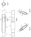
Fig. 7 is a sectioned view through the proximal portion of the tip for the catheter assembly ofFig. 4 ; -
Fig. 8 is a side view of the proximal portion of the tip; -
Fig. 9 is a sectioned view of the proximal portion of the tip as viewed along sectioned lines 9-9 ofFig. 7 ; -
Fig. 10 is an isometric view of the proximal portion of the tip; -
Fig. 11 is another isometric view of the proximal portion of the tip; -
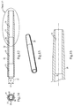
Fig. 12 is a side sectioned view of the distal portion of the tip for the catheter assembly ofFig. 4 ; -
Fig. 13 is an isometric view of the distal portion of the tip; -
Fig. 14 is an end view of the distal portion of the tip; -
Fig. 15 is an enlarged sectioned view of an end of the distal portion of the tip and identified asdetail 15 inFig. 12 ; -
Fig. 16 is a side schematic view of the molding process for the proximal portion of the tip; and -
Fig. 17 is side schematic view of the molding process for the distal portion of the tip. - Referring initially to
Figs. 1-3 , astent deployment system 10 includes acatheter assembly 20 that includes anelongate tube 21 with atip 22 attached to, and extending distally beyond, adistal end segment 23 of theelongate tube 21.Tip 22 generally has a larger outside diameter than an outside diameter ofelongate tube 21. Aself expanding stent 40 is compressed around acarrier segment 24 of theelongate tube 21. Aretractable sheath 50 is mounted on the catheter assembly, and is movable along acentral axis 30 of theelongate tube 21 between a pre-deployment configuration (as shown) and a post-deployment configuration. Theself expanding stent 40 and thecarrier segment 23 are covered by theretractable sheath 50 in the pre-deployment configuration. Theself expanding stent 40 is un-covered, and adistal end 51 of theretractable sheath 50 is located proximally of thecarrier segment 23, in the post-deployment configuration. In the illustrated embodiment, thestent deployment system 10 utilizes athumbwheel assembly 13 in order to moveretractable sheath 50 between its pre-deployment configuration, as shown, and the post-deployment configuration.Stent deployment system 10 may include anouter sheath 14, that has an internal lumen sized to receiveretractable sheath 50 andcatheter assembly 20, includingtip 22. Apull 15 has a proximal end wound ontospool 16 and a distal end attached toretractable sheath 50. In this way,retractable sheath 50 moves from the pre-deployment configuration to the post-deployment configuration responsive to rotation of the thumbwheel of thethumbwheel assembly 13 to wind pull 15 ontospool 16. Thestent deployment system 10 may also include apusher catheter 17 with apusher band 18 mounted on its distal end to maintainself expanding stent 40 at a desired location alongcentral axis 30 whenretractable sheath 50 is being slid from the pre-deployment configuration to the post-deployment configuration. Although thestent deployment system 10 is shown utilizing athumbwheel assembly 13, those skilled in the art will appreciate that a conventional pin and pull structure for maneuveringretractable sheath 50 would also fall within the intended scope of the present disclosure. Stentdeployment system 10 has structure similar to stent deployment systems well known in the art, with the exception of the structure oftip 22, and the overall structure ofcatheter assembly 20 in general. - Referring in addition to
Figs. 4-6 theelongate tube 21 ofcatheter assembly 20 may be formed from a suitable thermosetting polyimide in order to facilitate overmolding atip 22 of polyether block amide. Unlike prior art structures, thedistal end segment 23 of theelongate tube 21 has an untreatedexternal surface 25 along anentire length 26 of thedistal end segment 23. The phrase "untreated external surface" means that theexternal surface 25 has not been manipulated or changed in any way to facilitate attachment oftip 22. Thus, the untreatedexternal surface 25 has no flange on its distal end, and includes no texturing or other surface features that are anything but parallel withcentral axis 30 such that theexternal surface 25 is identical to the external surface ofcarrier segment 24 and maybe all of the remaining portions of theelongate tube 21 away fromdistal end segment 23. Thetip 22 includes aproximal portion 27 that is molecularly joined to adistal portion 28, which has a lower durometer hardness than theproximal portion 27. The term "molecularly joined" means that theproximal portion 27 and thedistal portion 28 are molded from the same or sufficiently similar plastic materials that theproximal portion 27 and thedistal portion 28 intermix with each other at their interface during the molding process oftip 22, before theentire tip 22 has solidified. The underlyingelongate tube 21 remains solid during the entire two shot molding process oftip 22. - Referring now in addition to
Figs. 7-13 , theproximal portion 27 includes ananchor surface 29 in contact with thedistal portion 28, and oriented perpendicular to thecentral axis 30 of theelongate tube 21. Although not necessary,distal portion 28 of thetip 22 may be in contact with theelongate tube 21 through a window 31 defined by theproximal portion 27. Thus, in the illustrated embodiment, thetip 22 maintains attachment to elongatetube 21 without reliance upon anchoring features textured into or formed on theelongate tube 21, as in the prior art. Thus, the untreatedexternal surface 25 has no anchoring features, which are surfaces oriented at an angle greater than zero with respect to thecenterline 30. Although not necessary, theproximal portion 27 may be shorter than thedistal portion 28 alongcentral axis 30. In the illustrated embodiment,proximal portion 27 includes a pair of anchor surfaces 29 that are located on opposite sides ofcentral axis 30, as best shown inFigs. 7-11 . Although not necessary,proximal portion 27 may include auniform diameter segment 33 that has a same diameter as auniform diameter segment 34 of thedistal portion 28. As best shown inFig. 12 , thedistal portion 28 oftip 22 may define threeconsecutive segments 35 that each define different internal diameters. One of theinternal diameters 36 matches anoutside diameter 37 of theelongate tube 21, and another one of theinternal diameters 38 matches aninternal diameter 39 of theelongate tube 21. These features may help to avoid discontinuities between the distal end of theelongate tube 21 and the corresponding features oftip 22. - Although not necessary,
proximal portion 27 anddistal portion 28 may be formed from different colors of a suitable plastic material, such as polyether block amide, so that theproximal portion 27 visibly contrasts with thedistal portion 28 to define acontrast line 32 that encircles thecentral axis 30, as best shown inFig. 4 . When thestent deployment system 10 is in the pre-deployment configuration, as shown, thedistal end 51 ofretractable sheath 50 and thecontrast line 32 may have corresponding positions along thecentral axis 30. Thus, thecontrast line 32 can be utilized at the time of manufacture to correctly set the corresponding relative positions of the retractable sheath relative to thecatheter assembly 20 in the pre-deployment configuration. Although not necessary, thecontrast line 32 may be located proximal to the anchor surface(s) 29 alongcentral axis 30. - The
stent deployment system 10 of the present disclosure is generally applicable to the delivery of self expanding stents. This disclosure is specifically applicable to the construction of acatheter assembly 20 that includes anelongate tube 21 with anovermolded tip 22. - One method of making the
stent deployment system 10 includesovermolding tip 22 of polyether block amide on an untreatedexternal surface 25 of adistal end segment 23 of anelongate tube 21 of thermosetting polyimide. Those skilled in the art will appreciate that other known materials with similar characteristics and behaviors may be substituted in place of the thermosetting polyimide and polyether block amide identified with respect to the illustrated embodiment. Thetip 22 may be molded in two steps as illustrated inFigs. 16 and 17 . In particular, the step ofovermolding tip 22 includes molding theproximal portion 27 oftip 22 with a first polyether block amide material, and then molding thedistal portion 28 oftip 22 with a second polyether block amide. The second polyether block amide has a lower durometer hardness when solidified that the first polyether block amide material, and may be of a different color to facilitate formation of thecontrast line 32 discussed earlier.Fig. 16 is useful for showing theproximal portion 27 being overmolded onto thedistal end segment 23 ofelongate tube 21 when amold 60 is oriented in a vertical orientation. Thus, theelongate tube 21 functions as a core infirst mold 60. The arrows inFig. 16 show that the material used for formingproximal portion 27 may entermold 60 through two gates. Nevertheless, any number of gates could be used in the injection molding process. After removal frommold 60, the piece may be inspected and any flash or excess material removed along mold lines or the like in a manner well known in the art. Thedistal portion 28 is then overmolded ontoproximal portion 27, amandrel core 63 andelongate tube 21 with asecond mold 61, which may be oriented in a horizontal orientation as shown inFig. 17 . Thus, theelongate tube 21 and theproximal portion 27 act as cores in thesecond mold 61. The molding ofproximal portion 27 includes forming an anchor surface(s) 29 that is oriented perpendicular to thecentral axis 30 ofelongate tube 21. The molding of thedistal portion 28, which is performed afterproximal portion 27 has solidified, includes contacting thedistal portion 28 with the anchor surface(s) 29 ofproximal portion 27, and molecularly joining thedistal portion 28 to theproximal portion 27 at their interface. The molecular joining is facilitated by the molten material fordistal portion 28 melting contact surfaces ofproximal portion 27 prior distal portion solidifying. After removal frommold 61,mandrel core 63 is removed and any excess material from mold joints and/or gates may be removed in a manner well known in the art. - After constructing
catheter assembly 20, aself expanding stent 40 is compressed and loaded into aretractable sheath 50. Later in theassembly catheter assembly 20 is back loaded intoretractable sheath 50 and throughself expanding stent 40 to a pre-deployment configuration at which theexpandable stent 40 and thecarrier segment 24 are covered by theretractable sheath 50. - Referring again specifically to
Fig. 16 and 17 , the arrows are used to indicate the injection molding process and possible gate locations at which the polyether block amide material might be injected into therespective molds distal portion 28 may include moving the second polyether block amide into contact with theelongate tube 21 through a window 31 defined by theproximal portion 27. By utilizing differing colors in the first and second polyether block amide materials, avisible contract line 32 is made on thetip 22 that encircles thecentral axis 30. Thecontrast line 32 may assist manufacturing personnel by providing a visible location to enable thedistal end 51 of the retractable sheath to be positioned at a corresponding position alongcentral axis 30 with thecontrast line 32. As stated earlier, thecontrast line 32 may be located during the molding process to be proximal to the anchor surface(s) 29 alongcentral axis 30. Likewise, theproximal portion 27 may be sized to be shorter than thedistal portion 28 alongcentral axis 30. Also as stated earlier, theproximal portion 27 may be shaped to have auniform diameter segment 33 that has a same diameter has auniform diameter segment 34 ofdistal portion 28. - The overmolding strategy of the present disclosure provides several advantages. First, the
elongate tube 21 need not be processed to include anchor features such as flanges or external texturing in order to facilitate attachment to anovermolded tip 22. Furthermore, by utilizing a two step process inovermolding tip 22, thedistal portion 28 can utilize a lower durometer hardness than theproximal portion 27 in order to provide texture and flexibility that physicians have come to recognize and expect. Finally, by utilizing the two shot injection overmolding strategy of the present disclosure, the catheter assemblies can be made more uniform in the manufacturing process with less reliance upon custom handmade tips associated with catheter assemblies of the past. - It should be understood that the above description is intended for illustrative purposes only, and is not intended to limit the scope of the present disclosure in any way. Thus, those skilled in the art will appreciate that other aspects of the disclosure can be obtained from a study of the drawings, the disclosure and the appended claims.
Claims (14)
- A stent deployment system comprising:a catheter assembly that includes an elongate tube with a tip attached to, and extending distally beyond, a distal end segment of the elongate tube;a self expanding stent compressed around a carrier segment of the elongate tube;a retractable sheath mounted on the catheter assembly, and being moveable along a central axis of the elongate tube between a pre-deployment configuration, at which the expandable stent and the carrier segment are covered, and a post-deployment configuration at which the expandable stent is uncovered and a distal end of the retractable sheath is located proximally of the carrier segment;the distal end segment of the elongate tube has an untreated external surface along an entire length of the distal end segment;the tip includes a proximal portion molecularly joined to a distal portion, which has a lower durometer hardness than the proximal portion; andthe proximal portion includes an anchor surface in contact with the distal portion and oriented perpendicular to the central axis of the elongate tube.
- The stent deployment system of claim 1 wherein the distal portion of the tip being in contact with the elongate tube through a window defined by the proximal portion.
- The stent deployment system of any one of the preceding claims wherein the proximal portion visibly contrasts with the distal portion to define a contrast line that encircles the central axis.
- The stent deployment system of claim 3 wherein the distal end of the retractable sheath and the contrast line have corresponding positions along the central axis.
- The stent deployment system of claim 3 or claim 4 wherein the contrast line is proximal to the anchor surface along the central axis.
- The stent deployment system of any one of the preceding claims wherein the proximal portion of the tip is shorter than the distal portion of the tip.
- The stent deployment system of any one of the preceding claims wherein the proximal portion has a uniform diameter segment that has a same diameter as a uniform diameter segment of the distal portion.
- The stent deployment system of any one of the preceding claims wherein the anchor surface is one of a pair of anchor surfaces that are located on opposite sides of the central axis.
- The stent deployment system of any one of the preceding claims wherein the distal portion of the tip defines three consecutive segments that each define different internal diameters; and
one of the internal diameters matches an outside diameter of the elongate tube, and an other one of the internal diameters matches an internal diameter of the elongate tube. - A method of making a stent deployment system, comprising the steps of:overmolding a tip on an untreated external surface of a distal end segment of an elongate tube of thermosetting polyimide;wherein the overmolding step includes molding a proximal portion of the tip with a first molding material, and then molding a distal portion of the tip with a second molding material, which has a lower durometer hardness when solidified than the first material;wherein the step of molding the proximal portion includes forming an anchor surface that is oriented perpendicular to a central axis of the elongate tube;wherein the step of molding the distal portion includes contacting the distal portion with the anchor surface of the proximal portion, and molecularly joining the distal portion to the proximal portion;compressing a self expanding stent around a carrier segment of the elongate tube;mounting a retractable sheath on the catheter assembly in a pre-deployment configuration at which the expandable stent and the carrier segment are covered by the retractable sheath.
- The method of claim 10 wherein the first and second molding materials are polyether block amides, preferably of contrasting colors.
- The method of claim 10 or claim 11 wherein the step of molding the distal portion includes moving the second polyether block amide into contact with the elongate tube through a window defined by the proximal portion.
- The method of any one of claim 10 to claim 12 including positioning a distal end of the retractable sheath and the contrast line at corresponding positions along the central axis.
- The method of any one of claim 10 to claim 13 used to make the stent deployment system of any one of claim 1 to claim 9.
Applications Claiming Priority (1)
| Application Number | Priority Date | Filing Date | Title |
|---|---|---|---|
| US201562120558P | 2015-02-25 | 2015-02-25 |
Publications (2)
| Publication Number | Publication Date |
|---|---|
| EP3061425A1 true EP3061425A1 (en) | 2016-08-31 |
| EP3061425B1 EP3061425B1 (en) | 2019-02-27 |
Family
ID=55080032
Family Applications (1)
| Application Number | Title | Priority Date | Filing Date |
|---|---|---|---|
| EP16150459.2A Active EP3061425B1 (en) | 2015-02-25 | 2016-01-07 | Stent deployment system with overmolded tip |
Country Status (2)
| Country | Link |
|---|---|
| US (3) | US10076435B2 (en) |
| EP (1) | EP3061425B1 (en) |
Families Citing this family (2)
| Publication number | Priority date | Publication date | Assignee | Title |
|---|---|---|---|---|
| US10076435B2 (en) * | 2015-02-25 | 2018-09-18 | Cook Medical Technologies Llc | Stent deployment system with overmolded tip |
| USD1064249S1 (en) | 2021-01-29 | 2025-02-25 | Samuel Albert | Myringotomy tube |
Citations (3)
| Publication number | Priority date | Publication date | Assignee | Title |
|---|---|---|---|---|
| US20020183826A1 (en) * | 2000-11-13 | 2002-12-05 | Angiomed Gmbh & Co. | Implant delivery device |
| US20070118201A1 (en) * | 2003-09-02 | 2007-05-24 | Pappas Jeffrey M | Delivery system for a medical device |
| US20130012924A1 (en) * | 2011-07-06 | 2013-01-10 | Boston Scientific Scimed, Inc. | Dual Durometer Soft/Flexible Enhanced Bond Strength Guiding Tip |
Family Cites Families (11)
| Publication number | Priority date | Publication date | Assignee | Title |
|---|---|---|---|---|
| US4753765A (en) | 1984-03-08 | 1988-06-28 | Cordis Corporation | Method of making a catheter having a fuseless tip |
| US5240537A (en) | 1991-07-01 | 1993-08-31 | Namic U.S.A. Corporation | Method for manufacturing a soft tip catheter |
| US5772641A (en) * | 1995-12-12 | 1998-06-30 | Medi-Dyne Inc. | Overlapping welds for catheter constructions |
| US5762637A (en) | 1996-08-27 | 1998-06-09 | Scimed Life Systems, Inc. | Insert molded catheter tip |
| US6149996A (en) | 1998-01-15 | 2000-11-21 | Schneider (Usa) Inc. | Molded tip and tubing and method of making same |
| EP0941713B1 (en) * | 1998-03-04 | 2004-11-03 | Schneider (Europe) GmbH | Device to insert an endoprosthesis into a catheter shaft |
| GB9807856D0 (en) | 1998-04-15 | 1998-06-10 | Smiths Industries Plc | Medico-surgical tubes and methods of manufacture |
| US9468462B2 (en) | 2012-11-19 | 2016-10-18 | Cook Medical Technologies Llc | Catheter and support cannula assembly |
| US9433521B2 (en) * | 2012-11-27 | 2016-09-06 | Medtronic, Inc. | Distal tip for a delivery catheter |
| WO2014143229A1 (en) | 2013-03-15 | 2014-09-18 | United Technologies Corporation | Abrasive tipped blades and manufacture methods |
| US10076435B2 (en) * | 2015-02-25 | 2018-09-18 | Cook Medical Technologies Llc | Stent deployment system with overmolded tip |
-
2015
- 2015-11-06 US US14/934,859 patent/US10076435B2/en active Active
-
2016
- 2016-01-07 EP EP16150459.2A patent/EP3061425B1/en active Active
-
2018
- 2018-08-09 US US16/059,636 patent/US10716693B2/en active Active
- 2018-08-09 US US16/059,575 patent/US10806618B2/en active Active
Patent Citations (3)
| Publication number | Priority date | Publication date | Assignee | Title |
|---|---|---|---|---|
| US20020183826A1 (en) * | 2000-11-13 | 2002-12-05 | Angiomed Gmbh & Co. | Implant delivery device |
| US20070118201A1 (en) * | 2003-09-02 | 2007-05-24 | Pappas Jeffrey M | Delivery system for a medical device |
| US20130012924A1 (en) * | 2011-07-06 | 2013-01-10 | Boston Scientific Scimed, Inc. | Dual Durometer Soft/Flexible Enhanced Bond Strength Guiding Tip |
Also Published As
| Publication number | Publication date |
|---|---|
| US10806618B2 (en) | 2020-10-20 |
| US10076435B2 (en) | 2018-09-18 |
| EP3061425B1 (en) | 2019-02-27 |
| US10716693B2 (en) | 2020-07-21 |
| US20180344496A1 (en) | 2018-12-06 |
| US20160242942A1 (en) | 2016-08-25 |
| US20180344495A1 (en) | 2018-12-06 |
Similar Documents
| Publication | Publication Date | Title |
|---|---|---|
| US4577543A (en) | Construction of a monolithic reinforced catheter with flexible portions | |
| US10716693B2 (en) | Stent deployment system with overmolded tip | |
| DE69529216T2 (en) | Self-sealing injection device and method of making same | |
| DE69229555T2 (en) | Radiation-opaque, non-kinkable, thin-walled insertion device | |
| US7862167B2 (en) | Linear element, especially a spectacle side, and method of producing it | |
| US4448741A (en) | Method of molding plastic workpieces about slender permanent inserts | |
| CN105363131A (en) | Method for producing magnetic therapy appliance | |
| EP1557257B1 (en) | Method for producing a wrapped tube made of thermoplastic material | |
| US11160684B2 (en) | Autostable bicanalicular probe | |
| EP2773499B1 (en) | Process for producing a reinforced plastic article | |
| JPS602978B2 (en) | Method for manufacturing a reinforced endless toothed belt made of plastic with a negative tolerance of belt circumference | |
| EP0306615B1 (en) | Method for manufacturing sabot projectiles | |
| DE102015102640A1 (en) | Production of a fabric hose reinforced plastic hose | |
| DE69508105T2 (en) | PLASTIC PIPE, EXTRUSION NOZZLE AND METHOD FOR PRODUCING SUCH PLASTIC TUBES | |
| JPH0332376B2 (en) | ||
| JP5350685B2 (en) | Manufacturing method for pipe joints | |
| DE19944513C1 (en) | Extrusion of plastic high-tension insulator involves injection molding insulator rings round a core with split die moving along core | |
| DE4302693C2 (en) | Guide wire, in particular for medical purposes | |
| WO2014040778A1 (en) | Gaiter and method for producing a gaiter | |
| DE4128584C2 (en) | Fishing rod and method of making it | |
| DE1956768A1 (en) | Monitoring device for conveyor belts | |
| JP2505666B2 (en) | Electric fusion splicer manufacturing equipment | |
| JP6345021B2 (en) | Side by side | |
| JP2002272322A (en) | Fishing rod | |
| DE19718096C2 (en) | Method for attaching a molded part encompassing a hose to a hose section |
Legal Events
| Date | Code | Title | Description |
|---|---|---|---|
| PUAI | Public reference made under article 153(3) epc to a published international application that has entered the european phase |
Free format text: ORIGINAL CODE: 0009012 |
|
| AK | Designated contracting states |
Kind code of ref document: A1 Designated state(s): AL AT BE BG CH CY CZ DE DK EE ES FI FR GB GR HR HU IE IS IT LI LT LU LV MC MK MT NL NO PL PT RO RS SE SI SK SM TR |
|
| AX | Request for extension of the european patent |
Extension state: BA ME |
|
| STAA | Information on the status of an ep patent application or granted ep patent |
Free format text: STATUS: REQUEST FOR EXAMINATION WAS MADE |
|
| 17P | Request for examination filed |
Effective date: 20170203 |
|
| RBV | Designated contracting states (corrected) |
Designated state(s): AL AT BE BG CH CY CZ DE DK EE ES FI FR GB GR HR HU IE IS IT LI LT LU LV MC MK MT NL NO PL PT RO RS SE SI SK SM TR |
|
| STAA | Information on the status of an ep patent application or granted ep patent |
Free format text: STATUS: EXAMINATION IS IN PROGRESS |
|
| 17Q | First examination report despatched |
Effective date: 20170425 |
|
| GRAP | Despatch of communication of intention to grant a patent |
Free format text: ORIGINAL CODE: EPIDOSNIGR1 |
|
| STAA | Information on the status of an ep patent application or granted ep patent |
Free format text: STATUS: GRANT OF PATENT IS INTENDED |
|
| INTG | Intention to grant announced |
Effective date: 20180622 |
|
| GRAS | Grant fee paid |
Free format text: ORIGINAL CODE: EPIDOSNIGR3 |
|
| GRAJ | Information related to disapproval of communication of intention to grant by the applicant or resumption of examination proceedings by the epo deleted |
Free format text: ORIGINAL CODE: EPIDOSDIGR1 |
|
| GRAL | Information related to payment of fee for publishing/printing deleted |
Free format text: ORIGINAL CODE: EPIDOSDIGR3 |
|
| STAA | Information on the status of an ep patent application or granted ep patent |
Free format text: STATUS: EXAMINATION IS IN PROGRESS |
|
| INTC | Intention to grant announced (deleted) | ||
| GRAR | Information related to intention to grant a patent recorded |
Free format text: ORIGINAL CODE: EPIDOSNIGR71 |
|
| STAA | Information on the status of an ep patent application or granted ep patent |
Free format text: STATUS: GRANT OF PATENT IS INTENDED |
|
| INTG | Intention to grant announced |
Effective date: 20181217 |
|
| GRAA | (expected) grant |
Free format text: ORIGINAL CODE: 0009210 |
|
| STAA | Information on the status of an ep patent application or granted ep patent |
Free format text: STATUS: THE PATENT HAS BEEN GRANTED |
|
| AK | Designated contracting states |
Kind code of ref document: B1 Designated state(s): AL AT BE BG CH CY CZ DE DK EE ES FI FR GB GR HR HU IE IS IT LI LT LU LV MC MK MT NL NO PL PT RO RS SE SI SK SM TR |
|
| REG | Reference to a national code |
Ref country code: GB Ref legal event code: FG4D |
|
| REG | Reference to a national code |
Ref country code: CH Ref legal event code: EP |
|
| REG | Reference to a national code |
Ref country code: AT Ref legal event code: REF Ref document number: 1100264 Country of ref document: AT Kind code of ref document: T Effective date: 20190315 |
|
| REG | Reference to a national code |
Ref country code: IE Ref legal event code: FG4D |
|
| REG | Reference to a national code |
Ref country code: DE Ref legal event code: R096 Ref document number: 602016010202 Country of ref document: DE |
|
| REG | Reference to a national code |
Ref country code: NL Ref legal event code: MP Effective date: 20190227 |
|
| REG | Reference to a national code |
Ref country code: LT Ref legal event code: MG4D |
|
| PG25 | Lapsed in a contracting state [announced via postgrant information from national office to epo] |
Ref country code: SE Free format text: LAPSE BECAUSE OF FAILURE TO SUBMIT A TRANSLATION OF THE DESCRIPTION OR TO PAY THE FEE WITHIN THE PRESCRIBED TIME-LIMIT Effective date: 20190227 Ref country code: PT Free format text: LAPSE BECAUSE OF FAILURE TO SUBMIT A TRANSLATION OF THE DESCRIPTION OR TO PAY THE FEE WITHIN THE PRESCRIBED TIME-LIMIT Effective date: 20190627 Ref country code: NO Free format text: LAPSE BECAUSE OF FAILURE TO SUBMIT A TRANSLATION OF THE DESCRIPTION OR TO PAY THE FEE WITHIN THE PRESCRIBED TIME-LIMIT Effective date: 20190527 Ref country code: FI Free format text: LAPSE BECAUSE OF FAILURE TO SUBMIT A TRANSLATION OF THE DESCRIPTION OR TO PAY THE FEE WITHIN THE PRESCRIBED TIME-LIMIT Effective date: 20190227 Ref country code: NL Free format text: LAPSE BECAUSE OF FAILURE TO SUBMIT A TRANSLATION OF THE DESCRIPTION OR TO PAY THE FEE WITHIN THE PRESCRIBED TIME-LIMIT Effective date: 20190227 Ref country code: LT Free format text: LAPSE BECAUSE OF FAILURE TO SUBMIT A TRANSLATION OF THE DESCRIPTION OR TO PAY THE FEE WITHIN THE PRESCRIBED TIME-LIMIT Effective date: 20190227 |
|
| PG25 | Lapsed in a contracting state [announced via postgrant information from national office to epo] |
Ref country code: BG Free format text: LAPSE BECAUSE OF FAILURE TO SUBMIT A TRANSLATION OF THE DESCRIPTION OR TO PAY THE FEE WITHIN THE PRESCRIBED TIME-LIMIT Effective date: 20190527 Ref country code: GR Free format text: LAPSE BECAUSE OF FAILURE TO SUBMIT A TRANSLATION OF THE DESCRIPTION OR TO PAY THE FEE WITHIN THE PRESCRIBED TIME-LIMIT Effective date: 20190528 Ref country code: IS Free format text: LAPSE BECAUSE OF FAILURE TO SUBMIT A TRANSLATION OF THE DESCRIPTION OR TO PAY THE FEE WITHIN THE PRESCRIBED TIME-LIMIT Effective date: 20190627 Ref country code: HR Free format text: LAPSE BECAUSE OF FAILURE TO SUBMIT A TRANSLATION OF THE DESCRIPTION OR TO PAY THE FEE WITHIN THE PRESCRIBED TIME-LIMIT Effective date: 20190227 Ref country code: LV Free format text: LAPSE BECAUSE OF FAILURE TO SUBMIT A TRANSLATION OF THE DESCRIPTION OR TO PAY THE FEE WITHIN THE PRESCRIBED TIME-LIMIT Effective date: 20190227 Ref country code: RS Free format text: LAPSE BECAUSE OF FAILURE TO SUBMIT A TRANSLATION OF THE DESCRIPTION OR TO PAY THE FEE WITHIN THE PRESCRIBED TIME-LIMIT Effective date: 20190227 |
|
| REG | Reference to a national code |
Ref country code: AT Ref legal event code: MK05 Ref document number: 1100264 Country of ref document: AT Kind code of ref document: T Effective date: 20190227 |
|
| PG25 | Lapsed in a contracting state [announced via postgrant information from national office to epo] |
Ref country code: IT Free format text: LAPSE BECAUSE OF FAILURE TO SUBMIT A TRANSLATION OF THE DESCRIPTION OR TO PAY THE FEE WITHIN THE PRESCRIBED TIME-LIMIT Effective date: 20190227 Ref country code: RO Free format text: LAPSE BECAUSE OF FAILURE TO SUBMIT A TRANSLATION OF THE DESCRIPTION OR TO PAY THE FEE WITHIN THE PRESCRIBED TIME-LIMIT Effective date: 20190227 Ref country code: EE Free format text: LAPSE BECAUSE OF FAILURE TO SUBMIT A TRANSLATION OF THE DESCRIPTION OR TO PAY THE FEE WITHIN THE PRESCRIBED TIME-LIMIT Effective date: 20190227 Ref country code: CZ Free format text: LAPSE BECAUSE OF FAILURE TO SUBMIT A TRANSLATION OF THE DESCRIPTION OR TO PAY THE FEE WITHIN THE PRESCRIBED TIME-LIMIT Effective date: 20190227 Ref country code: ES Free format text: LAPSE BECAUSE OF FAILURE TO SUBMIT A TRANSLATION OF THE DESCRIPTION OR TO PAY THE FEE WITHIN THE PRESCRIBED TIME-LIMIT Effective date: 20190227 Ref country code: DK Free format text: LAPSE BECAUSE OF FAILURE TO SUBMIT A TRANSLATION OF THE DESCRIPTION OR TO PAY THE FEE WITHIN THE PRESCRIBED TIME-LIMIT Effective date: 20190227 Ref country code: SK Free format text: LAPSE BECAUSE OF FAILURE TO SUBMIT A TRANSLATION OF THE DESCRIPTION OR TO PAY THE FEE WITHIN THE PRESCRIBED TIME-LIMIT Effective date: 20190227 Ref country code: AL Free format text: LAPSE BECAUSE OF FAILURE TO SUBMIT A TRANSLATION OF THE DESCRIPTION OR TO PAY THE FEE WITHIN THE PRESCRIBED TIME-LIMIT Effective date: 20190227 |
|
| REG | Reference to a national code |
Ref country code: DE Ref legal event code: R097 Ref document number: 602016010202 Country of ref document: DE |
|
| PG25 | Lapsed in a contracting state [announced via postgrant information from national office to epo] |
Ref country code: PL Free format text: LAPSE BECAUSE OF FAILURE TO SUBMIT A TRANSLATION OF THE DESCRIPTION OR TO PAY THE FEE WITHIN THE PRESCRIBED TIME-LIMIT Effective date: 20190227 Ref country code: SM Free format text: LAPSE BECAUSE OF FAILURE TO SUBMIT A TRANSLATION OF THE DESCRIPTION OR TO PAY THE FEE WITHIN THE PRESCRIBED TIME-LIMIT Effective date: 20190227 |
|
| PG25 | Lapsed in a contracting state [announced via postgrant information from national office to epo] |
Ref country code: AT Free format text: LAPSE BECAUSE OF FAILURE TO SUBMIT A TRANSLATION OF THE DESCRIPTION OR TO PAY THE FEE WITHIN THE PRESCRIBED TIME-LIMIT Effective date: 20190227 |
|
| PLBE | No opposition filed within time limit |
Free format text: ORIGINAL CODE: 0009261 |
|
| STAA | Information on the status of an ep patent application or granted ep patent |
Free format text: STATUS: NO OPPOSITION FILED WITHIN TIME LIMIT |
|
| 26N | No opposition filed |
Effective date: 20191128 |
|
| PG25 | Lapsed in a contracting state [announced via postgrant information from national office to epo] |
Ref country code: SI Free format text: LAPSE BECAUSE OF FAILURE TO SUBMIT A TRANSLATION OF THE DESCRIPTION OR TO PAY THE FEE WITHIN THE PRESCRIBED TIME-LIMIT Effective date: 20190227 |
|
| PG25 | Lapsed in a contracting state [announced via postgrant information from national office to epo] |
Ref country code: TR Free format text: LAPSE BECAUSE OF FAILURE TO SUBMIT A TRANSLATION OF THE DESCRIPTION OR TO PAY THE FEE WITHIN THE PRESCRIBED TIME-LIMIT Effective date: 20190227 |
|
| PG25 | Lapsed in a contracting state [announced via postgrant information from national office to epo] |
Ref country code: MC Free format text: LAPSE BECAUSE OF FAILURE TO SUBMIT A TRANSLATION OF THE DESCRIPTION OR TO PAY THE FEE WITHIN THE PRESCRIBED TIME-LIMIT Effective date: 20190227 |
|
| REG | Reference to a national code |
Ref country code: CH Ref legal event code: PL |
|
| REG | Reference to a national code |
Ref country code: BE Ref legal event code: MM Effective date: 20200131 |
|
| PG25 | Lapsed in a contracting state [announced via postgrant information from national office to epo] |
Ref country code: LU Free format text: LAPSE BECAUSE OF NON-PAYMENT OF DUE FEES Effective date: 20200107 Ref country code: FR Free format text: LAPSE BECAUSE OF NON-PAYMENT OF DUE FEES Effective date: 20200131 |
|
| PG25 | Lapsed in a contracting state [announced via postgrant information from national office to epo] |
Ref country code: CH Free format text: LAPSE BECAUSE OF NON-PAYMENT OF DUE FEES Effective date: 20200131 Ref country code: BE Free format text: LAPSE BECAUSE OF NON-PAYMENT OF DUE FEES Effective date: 20200131 Ref country code: LI Free format text: LAPSE BECAUSE OF NON-PAYMENT OF DUE FEES Effective date: 20200131 |
|
| PG25 | Lapsed in a contracting state [announced via postgrant information from national office to epo] |
Ref country code: MT Free format text: LAPSE BECAUSE OF FAILURE TO SUBMIT A TRANSLATION OF THE DESCRIPTION OR TO PAY THE FEE WITHIN THE PRESCRIBED TIME-LIMIT Effective date: 20190227 Ref country code: CY Free format text: LAPSE BECAUSE OF FAILURE TO SUBMIT A TRANSLATION OF THE DESCRIPTION OR TO PAY THE FEE WITHIN THE PRESCRIBED TIME-LIMIT Effective date: 20190227 |
|
| PG25 | Lapsed in a contracting state [announced via postgrant information from national office to epo] |
Ref country code: MK Free format text: LAPSE BECAUSE OF FAILURE TO SUBMIT A TRANSLATION OF THE DESCRIPTION OR TO PAY THE FEE WITHIN THE PRESCRIBED TIME-LIMIT Effective date: 20190227 |
|
| P01 | Opt-out of the competence of the unified patent court (upc) registered |
Effective date: 20230602 |
|
| PGFP | Annual fee paid to national office [announced via postgrant information from national office to epo] |
Ref country code: GB Payment date: 20260126 Year of fee payment: 11 |
|
| PGFP | Annual fee paid to national office [announced via postgrant information from national office to epo] |
Ref country code: IE Payment date: 20260120 Year of fee payment: 11 Ref country code: DE Payment date: 20260127 Year of fee payment: 11 |