EP3060740B1 - Multi-angle rotary steerable drilling - Google Patents
Multi-angle rotary steerable drilling Download PDFInfo
- Publication number
- EP3060740B1 EP3060740B1 EP14856771.2A EP14856771A EP3060740B1 EP 3060740 B1 EP3060740 B1 EP 3060740B1 EP 14856771 A EP14856771 A EP 14856771A EP 3060740 B1 EP3060740 B1 EP 3060740B1
- Authority
- EP
- European Patent Office
- Prior art keywords
- shaft
- strike ring
- angular offset
- borehole
- angle strike
- Prior art date
- Legal status (The legal status is an assumption and is not a legal conclusion. Google has not performed a legal analysis and makes no representation as to the accuracy of the status listed.)
- Not-in-force
Links
- 238000005553 drilling Methods 0.000 title claims description 58
- 239000012530 fluid Substances 0.000 claims description 44
- 230000001419 dependent effect Effects 0.000 claims description 30
- 238000000034 method Methods 0.000 claims description 27
- 230000015572 biosynthetic process Effects 0.000 claims description 9
- 230000008878 coupling Effects 0.000 claims description 8
- 238000010168 coupling process Methods 0.000 claims description 8
- 238000005859 coupling reaction Methods 0.000 claims description 8
- 230000004044 response Effects 0.000 claims description 5
- 238000004891 communication Methods 0.000 description 9
- 230000008859 change Effects 0.000 description 8
- 238000005755 formation reaction Methods 0.000 description 8
- 230000003068 static effect Effects 0.000 description 7
- 230000007423 decrease Effects 0.000 description 3
- 230000008901 benefit Effects 0.000 description 2
- 238000010586 diagram Methods 0.000 description 2
- 230000008569 process Effects 0.000 description 2
- 238000005452 bending Methods 0.000 description 1
- 238000010276 construction Methods 0.000 description 1
- 238000005520 cutting process Methods 0.000 description 1
- 229910003460 diamond Inorganic materials 0.000 description 1
- 239000010432 diamond Substances 0.000 description 1
- 239000012208 gear oil Substances 0.000 description 1
- 230000001939 inductive effect Effects 0.000 description 1
- 239000000463 material Substances 0.000 description 1
- 230000035515 penetration Effects 0.000 description 1
- 230000003134 recirculating effect Effects 0.000 description 1
- UONOETXJSWQNOL-UHFFFAOYSA-N tungsten carbide Chemical compound [W+]#[C-] UONOETXJSWQNOL-UHFFFAOYSA-N 0.000 description 1
Images


Classifications
-
- E—FIXED CONSTRUCTIONS
- E21—EARTH DRILLING; MINING
- E21B—EARTH DRILLING, e.g. DEEP DRILLING; OBTAINING OIL, GAS, WATER, SOLUBLE OR MELTABLE MATERIALS OR A SLURRY OF MINERALS FROM WELLS
- E21B7/00—Special methods or apparatus for drilling
- E21B7/04—Directional drilling
-
- E—FIXED CONSTRUCTIONS
- E21—EARTH DRILLING; MINING
- E21B—EARTH DRILLING, e.g. DEEP DRILLING; OBTAINING OIL, GAS, WATER, SOLUBLE OR MELTABLE MATERIALS OR A SLURRY OF MINERALS FROM WELLS
- E21B7/00—Special methods or apparatus for drilling
- E21B7/04—Directional drilling
- E21B7/06—Deflecting the direction of boreholes
- E21B7/067—Deflecting the direction of boreholes with means for locking sections of a pipe or of a guide for a shaft in angular relation, e.g. adjustable bent sub
-
- E—FIXED CONSTRUCTIONS
- E21—EARTH DRILLING; MINING
- E21B—EARTH DRILLING, e.g. DEEP DRILLING; OBTAINING OIL, GAS, WATER, SOLUBLE OR MELTABLE MATERIALS OR A SLURRY OF MINERALS FROM WELLS
- E21B17/00—Drilling rods or pipes; Flexible drill strings; Kellies; Drill collars; Sucker rods; Cables; Casings; Tubings
- E21B17/16—Drill collars
-
- E—FIXED CONSTRUCTIONS
- E21—EARTH DRILLING; MINING
- E21B—EARTH DRILLING, e.g. DEEP DRILLING; OBTAINING OIL, GAS, WATER, SOLUBLE OR MELTABLE MATERIALS OR A SLURRY OF MINERALS FROM WELLS
- E21B3/00—Rotary drilling
- E21B3/02—Surface drives for rotary drilling
- E21B3/04—Rotary tables
Description
- This application claims the benefit of, and priority to, United States Non Provisional Patent Application Serial No.
14/062,963, filed October 25, 2013 - In downhole drilling operations, a rotary steerable system (RSS) is utilized to drill a well with one or more horizontal and/or otherwise deviated sections. For example, an RSS may initially drill vertically and then kick off at an angle to drill a lateral portion of a well in a single run. The extent to which an RSS can turn or build angle to form a dogleg portion of the well may be limited by control and steerability issues, which can result in a less than optimal rate of penetration (ROP).
-
US 2010/0000794 A1 discloses a drilling assembly comprising a collar being movable in an axial direction, wherein the position of the collar determines a maximum angular deflection of a drill bit.US 6,216,802 B1 discloses a steering system to directionally drill a wellbore through earth formations, the sytem comprising an orientation collar and a sliding sleeve with an internal bore which is not parallel to the center line of the orientation collar and can be used to adjust the center position of a bearing supporting a drive shaft carrying a drill bit. - The present disclosure introduces an apparatus comprising a shaft, a multi-angle strike ring axially repositionable along the shaft, and an articulated member coupled to the shaft. The apparatus may further comprise a steering member carried by the articulated member, and an actuator operable to maintain an angular offset of the articulated member relative to the shaft by maintaining azimuthally-dependent contact between the multi-angle strike ring and the steering member.
- The present disclosure also introduces a method comprising operating an actuator to maintain a first angular offset of an articulated member, relative to a shaft coupled to the articulated member, by maintaining azimuthally-dependent contact between: a multi-angle strike ring positioned in a first axial position relative to the shaft; and a steering member carried by the articulated member. Such method may further comprise axially translating the multi-angle strike ring along the shaft from the first axial position to a second axial position, and operating the actuator to maintain a second angular offset of the articulated member relative to the shaft by maintaining azimuthally-dependent contact between the steering member and the multi-angle strike ring positioned in the second axial position. The second angular offset may be substantially different than the first angular offset.
- The present disclosure also introduces a method comprising drilling a first portion of a borehole with a downhole tool by rotating a string of tubular members coupled to the downhole tool while operating an actuator of the downhole tool to maintain a first angular offset between axes of the downhole tool and a drill bit carried by the downhole tool. Such method may further comprise adjusting the first angular offset to a second angular offset by changing a pressure or flow rate of a drilling fluid flowing through the downhole tool from the string of tubular members, and drilling a second portion of the borehole with the downhole tool by rotating the string of tubular members while operating the actuator to maintain the second angular offset.
- Additional aspects of the present disclosure are set forth in the description that follows, and/or may be learned by a person having ordinary skill in the art by reading the materials herein and/or practicing the principles described herein. At least some aspects of the present disclosure may be achieved via means recited in the attached claims.
- The present disclosure is best understood from the following detailed description when read with the accompanying figures. It is emphasized that, in accordance with the standard practice in the industry, various features are not drawn to scale. In fact, the dimensions of the various features may be arbitrarily increased or reduced for clarity of discussion.
-
FIG. 1 is a schematic view of at least a portion of apparatus according to one or more aspects of the present disclosure. -
FIG. 2 is a schematic view of at least a portion of apparatus according to one or more aspects of the present disclosure. -
FIG. 3 is a schematic view of at least a portion of apparatus according to one or more aspects of the present disclosure. -
FIG. 4 is a schematic view of at least a portion of apparatus according to one or more aspects of the present disclosure. -
FIG. 5 is a schematic view of at least a portion of apparatus according to one or more aspects of the present disclosure. -
FIG. 6 is a schematic view of at least a portion of apparatus according to one or more aspects of the present disclosure. -
FIG. 7 is a schematic view of at least a portion of apparatus according to one or more aspects of the present disclosure. -
FIG. 8 is a flow-chart diagram of at least a portion of a method according to one or more aspects of the present disclosure. - It is to be understood that the following disclosure provides many different embodiments, or examples, for implementing different features of various embodiments. Specific examples of components and arrangements are described below to simplify the present disclosure. These are, of course, merely examples and are not intended to be limiting. In addition, the present disclosure may repeat reference numerals and/or letters in the various examples. This repetition is for the purpose of simplicity and clarity and does not in itself dictate a relationship between the various embodiments and/or configurations discussed.
-
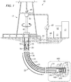
FIG. 1 is a schematic view of at least a portion of apparatus according to one or more aspects of the present disclosure. Depicted components include awellsite 10, arig 15, and adownhole tool 100 suspended from therig 15 in aborehole 20 via a drill string and/or other string oftubular members 25. Thedownhole tool 100 or a bottom hole assembly ("BHA") comprising thedownhole tool 100 comprises or is coupled to adrill bit 30 at its lower end, which is operable to advance thedownhole tool 100 into a formation 35 and form theborehole 20. The string oftubular members 25 may be rotated by a rotary table 40 that engages a kelly at the upper end of the string oftubular members 25. The string oftubular members 25 is suspended from ahook 45 attached to a traveling block (not shown) through the kelly and arotary swivel 50 that permits rotation of the string oftubular members 25 relative to thehook 45. - The
rig 15 is depicted as a land-based platform and derrick assembly utilized to form theborehole 20 by rotary drilling in a manner that is well known. However, a person having ordinary skill in the art will appreciate that one or more aspects of the present disclosure may also find application in other downhole implementations, and is not limited to land-based rigs. A person having ordinary skill in the art will also recognize that one or more aspects of the present disclosure may be applicable or readily adaptable for use with top drive systems in lieu of or addition to the above-described rotary table 40. - Drilling fluid (or "mud") 55 is stored in a
pit 60 formed at thewellsite 10. Apump 65 deliversdrilling fluid 55 to the interior of the string oftubular members 25 via a port in therotary swivel 50, inducing the drilling fluid to flow downward through the string oftubular members 25, as indicated inFIG. 1 bydirectional arrow 70. Thedrilling fluid 55 exits the string oftubular members 25 via ports in thedrill bit 30, and then circulates upward through the annulus defined between the outside of the string oftubular members 25 and the wall of theborehole 20, as indicated inFIG. 1 bydirection arrows 75. In this manner, thedrilling fluid 55 lubricates thedrill bit 30 and carries formation cuttings up to the surface as it is returned to thepit 60 for recirculation. - The
downhole tool 100 and/or BHA may be positioned near thedrill bit 30, perhaps within the length of several drill collars and/or othertubular members 25 from thedrill bit 30. Thedownhole tool 100 may comprise various components with various capabilities in addition to those providing steerability, such as measuring, processing, and storing information about thedownhole tool 100, the BHA, and/or the subterranean formation 35. A telemetry device (not shown) is also provided for communicating with one or more components ofsurface equipment 12, such as may comprise acquisition and/or control equipment. - The
downhole tool 100 may comprise ashaft 110, amulti-angle strike ring 120 repositionable along theshaft 110, an articulatedmember 130 coupled to theshaft 110, asteering member 140 carried by the articulatedmember 130, astrike ring actuator 150, and a plurality ofsteering member actuators 160. The articulatedmember 130 is articulated in the sense that it is coupled to theshaft 110 by auniversal joint 170. The articulatedmember 130 also provides the mechanical and fluidic interface between thedrill bit 30 and theuniversal joint 170 and/orshaft 110. The articulatedmember 130 may also be or comprise one or more flexible members. - The
universal joint 170 permits an angular offset between the articulatedmember 130 and theshaft 110 while still imparting rotation of theshaft 110 to the articulatedmember 130 and passingdrilling fluid 55 between internal passages of theshaft 110 and the articulatedmember 130. Thesteering member actuators 160 are collectively operable to maintain an angular offset of the articulatedmember 130 relative to theshaft 110 by maintaining azimuthally-dependent contact between themulti-angle strike ring 120 and thesteering member 140. Thedrill bit 30 may be a component of or otherwise coupled to the articulatedmember 130, may be fixed cutter, roller cone, and/or other types of bits, and may comprise polycrystalline diamond compact (PDC) inserts, grit hotpressed inserts (GHI), tungsten carbide inserts (TCI), milled teeth (MT), and/or other types of inserts, and/or cutters. -
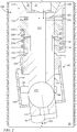
FIG. 2 is a sectional view of at least a portion of thedownhole tool 100 ofFIG. 1 . In operation, thesteering member actuators 160 cooperate to urge thesteering member 140 towards a firstangular offset 201 relative toshaft 110. Consequently, anuphole end 142 of thesteering member 140 contacts themulti-angle strike ring 120, whereby themulti-angle strike ring 120 constrains thesteering member 140 from bending/tilting beyond the firstangular offset 201. The resulting contact between theend 142 of thesteering member 140 and themulti-angle strike ring 120 is maintained in an azimuthally-dependent manner by cooperative operation of thesteering member actuators 160. - For example, referring to
FIGS. 1 and2 collectively, when thedownhole tool 100 is being operated to drill or elongate acurved trajectory portion 22 of theborehole 20, maintaining the azimuthally-dependent contact between themulti-angle strike ring 120 and thesteering member 140 comprises maintaining contact at a substantially constant azimuthal position relative to theborehole 20. The maintained contact (whether point contact, line contact, and/or surface contact) may vary azimuthally relative to theborehole 20, perhaps in proportion to rotation of theshaft 110 within theborehole 20. - In contrast, when the
downhole tool 100 is being operated to drill or elongate another portion 24 of theborehole 20 along a substantially and/or effectively straight trajectory, maintaining the azimuthally-dependent contact between themulti-angle strike ring 120 and thesteering member 140 comprises maintaining contact (whether point contact, line contact, and/or surface contact) that varies azimuthally relative to theborehole 20. An "effectively straight" trajectory may be that which is achieved via implementations in which thesteering member actuators 160 are cooperatively operable to maintain an angular offset of the steeringmember 140 relative to theshaft 110 but are not operable to maintain straight or coaxial alignment of the steeringmember 140 relative to the shaft 110 (i.e., an angular offset of zero degrees). As such, the azimuthally rotating contact between themulti-angle strike ring 120 and the steeringmember 140 may result in the elongation of theborehole 20 along a helical trajectory around a substantially straight axis. - Best shown in
FIG. 2 , thedownhole tool 100 and/or other portion of the BHA further comprises aninterface 180 for coupling theshaft 110 with the string oftubular members 25. Theinterface 180 may be or comprise a threaded recess configured to receive a threaded end of an adjacent one of thetubular members 25, such as where the coupling between theshaft 110 and the adjacenttubular member 25 is an industry-standard pin-box connection. However, other means may be utilized within the scope of the present disclosure to couple thedownhole tool 100 to the string oftubular members 25 and/or other borehole-conveyance means, including in implementations in which one or more intervening components are coupled between theshaft 110 and the adjacent conveyance member. - The
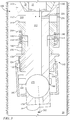
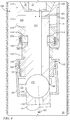
multi-angle strike ring 120 is axially repositionable along theshaft 110. For example, themulti-angle strike ring 120 may be axially repositionable between at least a first position on theshaft 110, such as the example position depicted inFIG. 2 , and a second position on theshaft 120, such as the example position depicted inFIG. 3 . The steeringmember actuators 160 and themulti-angle strike ring 120 may be collectively operable to maintain the first angular offset 201 of the articulatedmember 130 relative to theshaft 110 when themulti-angle strike ring 120 is in the first position (FIG. 2 ), and to maintain a second angular offset 202 of the articulatedmember 130 relative to theshaft 110 when themulti-angle strike ring 120 is in the second position (FIG. 3 ). Themulti-angle strike ring 120 may comprise afirst portion 122 contacting theend 142 of the steering member when themulti-angle strike ring 120 is in the first position (FIG. 2 ), and asecond portion 124 contacting theend 142 of the steering member when themulti-angle strike ring 120 is in the second position (FIG. 3 ). The first andsecond portions member 140 and themulti-angle strike ring 120, instead of merely point contact. - The first angular offset 201 may be about twice the second angular offset 202. For example, the first angular offset 201 may be about one degree, and the second angular offset 202 may be about one-half of a degree. However, these are merely examples, and other values are also within the scope of the present disclosure. To adjust the angular offset between the articulated
member 130 and theshaft 110, themulti-angle strike ring 120 may be axially repositionable along theshaft 110, perhaps in response to fluid pressure and/or flow rate changes within the string oftubular members 25. For example, referring toFIGS. 1-3 collectively, eachtubular member 25 may have aninternal passage 27 through whichdrilling fluid 55 may be pumped from the surface at thewellsite 10, as indicated inFIGS. 1-3 byarrows 70. Theshaft 110 may have aninternal passage 112 in fluid communication with theinternal passage 27 of the string oftubular members 25, and may thus receivedrilling fluid 55 from the string oftubular members 25. - The
internal passage 112 of theshaft 110 may be in direct or indirect fluid communication with achamber 210 of thedownhole tool 110. As shown inFIGS. 2-4 , thechamber 210 may be or comprise an annular volume defined by surfaces of theshaft 110, thestrike ring actuator 150, and aretainer 152. Theretainer 152 secures thestrike ring actuator 150 to theshaft 110 in a manner permitting axial translation of thestrike ring actuator 150 relative to theshaft 110. Fluid communication between thechamber 210 and theinternal passage 112 of theshaft 110 may be via a port, channel, valve, and/orother means 220. - An increase in the pressure and/or flow rate of the drilling fluid flow in the
internal passage 112 of theshaft 110 may act on anuphole surface 154 of thestrike ring actuator 150 and/or otherwise urge thestrike ring actuator 150 in a downhole direction. Such downhole motion of thestrike ring actuator 150 may be resisted by a biasingmember 230 positioned around thestrike ring actuator 150 and/or within anadditional chamber 240 of thedownhole tool 100. Thechamber 240 may be or comprise an annular volume defined by surfaces of thestrike ring actuator 150 and theretainer 152. - The
retainer 152 and/or another component of thedownhole tool 100 may comprise achoke 250 establishing fluid communication between thechamber 210 and theborehole 20. Thechoke 250 may be or comprise a passive or active valve, orifice, and/or other means restricting fluid communication from thechamber 210 to theborehole 20 and/or otherwise controlling the pressure and/or flow rate within thechamber 210. - In operation, a surface control system (such as may form a portion of the
surface equipment 12 shown inFIG. 1 ) may be utilized to communicate steering commands to electronics (not shown) in thedownhole tool 100 and/or other portion of the BHA, either directly or via one or more measurement-while-drilling (MWD) and/or logging-while-drilling (LWD) tools included among or carried by the string oftubular members 25. The steeringmember actuators 160 individually or collectively tilt the steeringmember 140, the articulatedmember 130, and thedrill bit 30 about theuniversal joint 170 with respect to theshaft 110 to maintain the angular offset 201/202 while all or part of the string oftubular members 25, the BHA, thedownhole tool 100, and thebit 30 are rotated at a "drill string" RPM. - The
universal joint 170 may transmit torque from theshaft 110 to thedrill bit 30 through the articulatedmember 130 and/or other intervening components. However, the torque may be separately transmitted via other arrangements, such as may comprise flex connections, splined couplings, gearing arrangements, ball and socket joints, and/or recirculating ball arrangements, among others within the scope of the present disclosure. In this context, theuniversal joint 170 is depicted schematically in the figures of the present disclosure, because the details regarding the make-up and construction of theuniversal joint 170 are not limited within the scope of the present disclosure. - The angular offset 201/202 and, therefore, the direction of the drill bit 30 (sometimes referred to as the tool-face or tool-face orientation) may thus determine the direction in which the
borehole 20 is being elongated. That is, the direction of thedrill bit 30 leads the direction of theborehole 20. This may allow for a rotary steerable system formed by or comprising thedownhole tool 100 to drill with little or no side force once a curve is established, and may minimize the amount of active control utilized to steer theborehole 20. - The steering
member actuators 160 may comprise one or more pistons, inflatable members, and/or other means acting on aninner periphery 144 of the steeringmember 140. The steeringmember actuators 160 may be sequentially actuated as the steeringmember 140 rotates, so that the angular offset 201/202 is maintained with respect to the formation 35 being drilled, such as during elongation of thecurved portion 22 of the borehole 20 shown inFIG. 1 . Thereafter, the steeringmember actuators 160 may be actuated to elongate theborehole 20 along an effectively straight trajectory, such as the substantially straight portion 24 of the borehole 20 shown inFIG. 1 . - When drilling along an effectively straight trajectory, the smallest angular offset attainable by adjusting the axial position of the
multi-angle strike ring 120 may be utilized, such as to decrease the radius of the helical trajectory of theborehole 20. For example, thesecond portion 124 of themulti-angle strike ring 120, corresponding to the smaller angular offset 202 (FIG. 3 ), may be utilized when drilling an effectively straight portion of theborehole 20. However, thefirst portion 122 of themulti-angle strike ring 120, corresponding to the larger angular offset 201 (FIG. 2 ), may be utilized when drilling a curved portion of theborehole 20, such as to attain a tighter turn radius (or a greater build angle). - As described above, the
multi-angle strike ring 120 may be axially repositioned along theshaft 110 by effecting a change in the pressure and/or flow rate of drilling fluid flowing past/into thechamber 210 and acting on thestrike ring actuator 150. Such change may be an increase or decrease relative to a predetermined threshold (e.g., normal or current operating pressure and/or flow rate), and/or a series of increases and/or decreases, such as in implementations utilizing more than two angular offsets. - Moreover, the axial position of the
multi-angle strike ring 120 may be maintained after each repositioning by the engagement of one ormore indexing members 190 within anindexing track 114 recessed within a substantiallycylindrical surface 116 of theshaft 110. InFIG. 5 , an "unrolled" view of a portion of thesurface 116 of theshaft 110 depicts an example implementation of theindexing track 114 in which one of theindexing members 190 may travel during repositioning of themulti-angle strike ring 120. Theindexing member 190 may be seated in a firststatic position 510 of theindexing track 114 when thestrike ring actuator 150 has been operated to position themulti-angle strike ring 120 in the first position, as shown inFIG. 2 . As thestrike ring actuator 150 is subsequently actuated by a change in the pressure and/or flow rate of the drilling fluid in thecentral passage 112 of theshaft 110, theindexing member 190 may travel along apath 520 of theindexing track 114 towards anintermediate position 530, corresponding to themulti-angle strike ring 120 being in the position shown inFIG. 4 . - The subsequent reversal of the change in the pressure and/or flow rate of the drilling fluid, and/or the biasing force of the biasing
member 230, may then cause theindexing member 190 to travel along apath 540 of theindexing track 114 to a secondstatic position 550, corresponding to themulti-angle strike ring 120 being positioned as shown inFIG. 3 (maintaining the second angular offset 202). - The
strike ring actuator 150 may be subsequently actuated by another change in the pressure and/or flow rate of the drilling fluid in thecentral passage 112 of theshaft 110, causing theindexing member 190 to travel along apath 560 of theindexing track 114 towards anotherintermediate position 570. The subsequent reversal of the change in the pressure and/or flow rate of the drilling fluid, and/or the biasing force of the biasingmember 230, may then cause theindexing member 190 to travel along apath 580 of theindexing track 114 to anotherstatic position 510, again corresponding to themulti-angle strike ring 120 being positioned to maintain the first angular offset 201, as shown inFIG. 2 . - The process may then be repeated for each instance that, for example, the drilling trajectory is switched between curved and straight (or effectively straight). That is, in the example implementation described above and shown in
FIGS. 2-5 , there are two static positions for themulti-angle strike ring 120, which correspond to the twoangular offsets member 130 and thedrill bit 30 relative to theshaft 110. Themulti-angle strike ring 120 may be alternatingly repositioned between the first and second static positions, which may correspond to the first and secondstatic positions more indexing members 190, as shown inFIG. 5 . However, the scope of the present disclosure also includes more complicated/sophisticated indexing tracks where, for example, the position of the multi-angle strike ring may be selectable by using half flow indexing, and/or themulti-angle strike ring 120 has more than two static positions, among other possible scenarios. -
FIG. 6 is a partial-sectional view of one such example, in which astrike ring actuator 650 comprising apiston head 652 and apiston rod 654 replaces thestrike ring actuator 150 of the implementation depicted inFIGS. 2-5 . Thepiston head 652 comprises opposingsurfaces shaft 110 and theretainer 152, define the boundaries of afirst chamber 610 and asecond chamber 640. Bothchambers internal passage 112 of theshaft 110 via operation of first andsecond valves - For example, the
first valve 612 may be or comprise a check valve and/or other type of valve. Thefirst valve 612 may be normally open when the pressure of the drilling fluid in theinternal passage 112 is below a predetermined pressure, but may close when the pressure of the drilling fluid exceeds the predetermined pressure. In contrast, while thesecond valve 642 may also be or comprise a check valve and/or other type of valve, it may be normally closed when the pressure of the drilling fluid is below the predetermined pressure, and may open when the pressure of the drilling fluid exceeds the predetermined pressure. Thepiston rod 654 is coupled to and/or otherwise extends from thedownhole surface 658 of thepiston head 652, through anopening 158 in theretainer 152, and to the multi-angle strike ring 620. Thus, thestrike ring actuator 650 and, therefore, the multi-angle strike ring 620, may be repositioned relative to theshaft 110 by adjusting the drilling fluid pressure in theinternal passage 112 of theshaft 110. - The
downhole tool 600 shown inFIG. 6 may also comprise a spring or other biasingmember 630, perhaps contained within thefirst chamber 610. The biasingmember 630 may be utilized to urge thestrike ring actuator 650 in a downhole direction, whether instead of or in conjunction with operation of one or bothvalves second chamber 640 may comprise a biasing member (not shown) that may be utilized to urge thestrike ring actuator 650 in an uphole direction, whether instead of or in conjunction with one or bothvalves - The
retainer 152 and/or another component of thedownhole tool 100 may comprise achoke 690 establishing fluid communication between thefirst chamber 610 and theborehole 20, and/or achoke 695 establishing fluid communication between thesecond chamber 640 and theborehole 20. Thechokes borehole 20, and/or otherwise controlling the pressure and/or flow rate within the corresponding chamber. -
FIG. 6 also demonstrates that the two-positionmulti-angle strike ring 150 shown inFIGS. 2-4 may be replaced by the multi-angle strike ring 620. The multi-angle strike ring 620 may have a single, substantiallyconical contact surface 622 that is contacted by the steeringmember 140, instead of the multiple contact surfaces of themulti-angle strike ring 120 depicted inFIGS. 2-4 . Thesingle contact surface 622 of the multi-angle strike ring 620 may allow for continuous adjustment between minimum and maximum values of the angular offset between the axes of theshaft 110 and the articulated member 130 (and, hence, the drill bit 30). - For example, when the
strike ring actuator 650 is fully extended, whether in response to the biasing force of the biasingmember 630 and/or the pressure differential created across thepiston head 652, the multi-angle strike ring 620 is positioned at its furthest downhole axial position, as shown inFIG. 6 . However, as shown in the sectional view of thedownhole tool 600 depictedFIG. 7 , when thestrike ring actuator 650 is axially repositioned in an uphole direction, whether in response to the biasing force of the biasingmember 630 and/or the pressure differential created across thepiston head 652, the multi-angle strike ring 620 is also axially repositioned in the uphole direction. Because the steeringmember actuators 160 continue to tilt the steeringmember 140 into contact with the multi-angle strike ring 620, the angular offset between the axes of theshaft 110 and the articulated member 130 (and, hence, the drill bit 30) increases, because theend 142 of the steeringmember 140 is now contacting a smaller-radius portion of the multi-angle strike ring 620. - Moreover, the full extension of the
strike ring actuator 650 may be greater than as depicted in the example shown inFIG. 6 . For example, thestrike ring actuator 650 and the multi-angle strike ring 620 may collectively be configured such that the angular offset (e.g., angular offset 201 inFIG. 2 and/or angular offset 202 inFIGS. 3 and4 ) may be maintained at substantially zero when thestrike ring actuator 650 is fully extended. In one or more of such implementations, the largest outer diameter OD of thestrike ring actuator 650 may be substantially equal to (or slightly larger than) the inner diameter ID of theinner periphery 144 of the multi-angle strike ring 620. As such, contact between thestrike ring actuator 650 and the multi-angle strike ring 620 may be line contact along a circle extending around thestrike ring actuator 650. In such configurations, the apparatus may be utilized to drill along a (substantially) literally straight trajectory, instead of the above-described effectively straight trajectory. - In the example implementation described above, drilling fluid ("mud") is utilized to cause movement of the
strike ring actuator 650. However, an internal hydraulic fluid (e.g., gear oil) may be utilized instead of (or in addition to) the drilling fluid. -
FIG. 8 is a flow-chart diagram of at least a portion of a method (800) according to one or more aspects of the present disclosure. The method (800) may be executed utilizing rotary steerable drilling apparatus having one or more aspects in common with the apparatus shown inFIGS. 1-7 and/or otherwise within the scope of the present disclosure. - The method (800) includes drilling (810) a first portion of a borehole with a downhole tool by rotating a string of tubular members coupled to the downhole tool while operating an actuator of the downhole tool to maintain a first angular offset between axes of the downhole tool and a drill bit carried by the downhole tool. For example, in the context of the example implementations shown in
FIGS. 1-7 , operating the actuator to maintain the first angular offset may include maintaining azimuthally-dependent contact between a multi-angle strike ring and a steering member, wherein the multi-angle strike ring may be positioned in a first axial position relative to a shaft of the downhole tool, the steering member may be carried by an articulated member of the downhole tool, and the drill bit may extend from the articulated member. - The first borehole portion may be substantially straight and/or effectively straight, such as where the first borehole portion follows a substantially helical trajectory having a substantially straight axis. For example, drilling the first borehole portion (810) may include maintaining the azimuthally-dependent contact between the multi-angle strike ring and the steering member as contact that varies azimuthally relative to the borehole. The maintained contact may vary azimuthally relative to the borehole in proportion to rotation of the shaft within the borehole, as function of time, and/or otherwise.
- After a predetermined time, or after the first borehole portion has been elongated to the intended length/depth, the first angular offset may be adjusted (820) to a second angular offset, such as by changing a pressure or flow rate of a drilling fluid flowing through the downhole tool from the string of tubular members. In the example implementations shown in
FIGS. 1-7 , such change in pressure and/or flow rate of the drilling fluid may axially translate the multi-angle strike ring along the shaft from the first axial position to a second axial position. - A second portion of the borehole may then be drilled (830) with the downhole tool by rotating the string of tubular members while operating the actuator to maintain the second angular offset. In the example implementations shown in
FIGS. 1-7 , operating the actuator to maintain the second angular offset of the articulated member relative to the shaft may include maintaining azimuthally-dependent contact between the steering member and the multi-angle strike ring positioned in the second axial position. - The second borehole portion may be substantially curved. For example, the azimuthally-dependent contact maintained between the multi-angle strike ring and the steering member may be substantially azimuthally-constant contact relative to the borehole.
- The second angular offset may be substantially greater than the first angular offset. For example, the second angular offset may be twice the first angular offset, such as in implementations in which the second angular offset is about one degree and the first angular offset is about one-half of a degree. Of course, other values for the first and second angular offsets are also within the scope of the present disclosure.
- After a predetermined time, or after the second borehole portion has been elongated to the intended length/depth, the second angular offset may be adjusted (840) back to the first angular offset, such as by again changing the pressure or flow rate of the drilling fluid flowing through the downhole tool from the string of tubular members. For example, such change in pressure and/or flow rate of the drilling fluid may axially translate the multi-angle strike ring along the shaft from the second axial position to the first axial position.
- A third portion of the borehole may then be drilled (850) with the downhole tool by rotating the string of tubular members while operating the actuator to maintain the first angular offset. For example, operating the actuator to maintain the first angular offset of the articulated member relative to the shaft may include maintaining azimuthally-dependent contact between the steering member and the multi-angle strike ring positioned in the first axial position. As with the first borehole portion, the third borehole portion may be substantially straight and/or effectively straight, although the effective axes of the first and third borehole portions may not extend in the same direction.
- The method (800) may include conveying a BHA comprising the downhole tool within the borehole while the first borehole portion is being drilled (810), while the second borehole portion is being drilled (830), and while the third borehole portion is being drilled (850), among other portions of the method (800). In the context of the example implementations shown in
FIGS. 1-7 , the BHA may be coupled to the string of tubulars, and may comprise the shaft, the multi-angle strike ring, the articulated member, the steering member, and the actuator of the downhole tool, and perhaps an interface for coupling with the string of tubular members. Drilling the first borehole portion (810), drilling the second borehole portion (830), and/or drilling the third borehole portion (850), among other portions of the method (800), may include rotating the BHA, such as by rotating the string of tubular members. - One or more aspects described above and/or shown in the figures may be presented in the context of a steerable tool platform having all-rotating, slowly-rotating, or non-rotating housings. However, a person having ordinary skill in the art will recognize that such aspects may be applicable or readily adaptable to each of such steerable tool platforms. Examples of such platforms may include those described within
U.S. Patent Application Serial No. 13/753,483 - The implementations described above are also presented in the context of a strike ring that is circumferentially continuous. However, other implementations are also within the scope of the present disclosure. For example, the strike ring may be circumferentially discontinuous, having a plurality of circumferentially spaced portions. In implementations comprising a plurality of portions spaced proximate or adjacent one another, the resulting strike ring may be substantially continuous along the circumference, even though the strike ring is not fully continuous. These and similar implementations may also be within the scope of the present disclosure.
- In view of all of the above, a person having ordinary skill in the art will readily recognize that the present disclosure introduces an apparatus comprising: a shaft; a multi-angle strike ring axially repositionable along the shaft; an articulated member coupled to the shaft; a steering member carried by the articulated member; and an actuator operable to maintain an angular offset of the articulated member relative to the shaft by maintaining azimuthally-dependent contact between the multi-angle strike ring and the steering member.
- Such apparatus may further comprise a bottom-hole assembly (BHA) comprising the shaft, the multi-angle strike ring, the articulated member, the steering member, the actuator, and an interface for coupling with a string of tubular members collectively operable to convey the BHA within a borehole extending into a subterranean formation. The articulated member may comprise a drill bit rotatable via rotation of the shaft. The multi-angle strike ring may be axially repositionable along the shaft in response to fluid pressure changes within the string of tubular members. The multi-angle strike ring may be axially repositionable between a first position on the shaft and a second position on the shaft, the actuator and the multi-angle strike ring may be collectively operable to maintain a first angular offset of the articulated member relative to the shaft when the multi-angle strike ring is in the first position and to maintain a second angular offset of the articulated member relative to the shaft when the multi-angle strike ring is in the second position, wherein the second angular offset may be substantially different than the first angular offset. The first angular offset may be about one degree and the second angular offset may be about one half of a degree. The multi-angle strike ring may be axially repositionable substantially continuously between the first and second positions.
- The apparatus may be positioned in a borehole being elongated along an effectively straight trajectory, and maintaining the azimuthally-dependent contact between the multi-angle strike ring and the steering member may comprise maintaining contact that varies azimuthally relative to the borehole. The maintained contact may vary azimuthally relative to the borehole in proportion to rotation of the shaft within the borehole.
- The apparatus may be positioned in a borehole being elongated along a curved trajectory, and maintaining the azimuthally-dependent contact between the multi-angle strike ring and the steering member may comprise maintaining contact at a substantially constant azimuthal position relative to the borehole.
- The present disclosure also introduces a method comprising: operating an actuator to maintain a first angular offset of an articulated member, relative to a shaft coupled to the articulated member, by maintaining azimuthally-dependent contact between: a multi-angle strike ring positioned in a first axial position relative to the shaft; and a steering member carried by the articulated member; axially translating the multi-angle strike ring along the shaft from the first axial position to a second axial position; and operating the actuator to maintain a second angular offset of the articulated member relative to the shaft by maintaining azimuthally-dependent contact between the steering member and the multi-angle strike ring positioned in the second axial position, wherein the second angular offset is substantially different than the first angular offset.
- Such method may further comprise conveying a bottom-hole assembly (BHA) coupled to a string of tubular members within a borehole extending into a subterranean formation, wherein the BHA comprises the shaft, the multi-angle strike ring, the articulated member, the steering member, the actuator, and an interface for coupling with the string of tubular members. The method may further comprise rotating the BHA by rotating the string of tubular members. Rotating the BHA may include rotating a drill bit of the articulated member. The method may further comprise elongating the borehole along an effectively straight trajectory by maintaining the azimuthally-dependent contact between the multi-angle strike ring and the steering member as contact that varies azimuthally relative to the borehole. The maintained contact may vary azimuthally relative to the borehole in proportion to rotation of the shaft within the borehole. The method may further comprise elongating the borehole along a curved trajectory by maintaining the azimuthally-dependent contact between the multi-angle strike ring and the steering member as substantially azimuthally-constant contact relative to the borehole.
- Axially translating the multi-angle strike ring along the shaft may comprise changing fluid pressure within the string of tubular members.
- The first angular offset may be about one degree and the second angular offset may be about one half of a degree.
- The multi-angle strike ring may be axially repositionable substantially continuously between the first and second axial positions.
- The present disclosure also introduces a method comprising: drilling a first portion of a borehole with a downhole tool by rotating a string of tubular members coupled to the downhole tool while operating an actuator of the downhole tool to maintain a first angular offset between axes of the downhole tool and a drill bit carried by the downhole tool; adjusting the first angular offset to a second angular offset by changing a pressure or flow rate of a drilling fluid flowing through the downhole tool from the string of tubular members; and drilling a second portion of the borehole with the downhole tool by rotating the string of tubular members while operating the actuator to maintain the second angular offset.
- Operating the actuator to maintain the first angular offset may comprise operating the actuator to maintain azimuthally-dependent contact between: a multi-angle strike ring positioned in a first axial position relative to a shaft of the downhole tool, wherein the multi-angle strike ring may be repositionable between the first axial position and a second axial position; and a steering member carried by an articulated member pivotally coupled to the shaft. The first borehole portion may be effectively substantially straight, and operating the actuator to maintain azimuthally-dependent contact between the steering member and the multi-angle strike ring in the first axial position may comprise maintaining contact that varies azimuthally relative to the borehole in proportion to rotation of the shaft within the borehole.
- Adjusting the first angular offset to the second angular offset may comprise axially translating the multi-angle strike ring along the shaft from the first axial position to the second axial position. Operating the actuator to maintain the second angular offset may comprise operating the actuator to maintain azimuthally-dependent contact between the steering member and the multi-angle strike ring positioned in the second axial position. The second borehole portion may follow a substantially curved trajectory, and operating the actuator to maintain the azimuthally-dependent contact between the steering member and the multi-angle strike ring in the second axial position may comprise maintaining the contact at a substantially constant azimuthal position relative to the borehole.
- The borehole may extend into a subterranean formation.
- The first borehole portion may follow a curved trajectory and the second portion may follow an effectively straight trajectory. The effectively straight trajectory may comprise a substantially helical trajectory along a substantially straight line.
- The first angular offset may be substantially greater than the second angular offset.
- The first angular offset may be about one-half of a degree and the second angular offset may be about one degree.
- The downhole tool may form at least a portion of a rotary steerable system.
- Adjusting the first angular offset to the second angular offset may comprise changing fluid pressure within the string of tubular members.
- The foregoing outlines features of several embodiments so that a person having ordinary skill in the art may better understand the aspects of the present disclosure. A person having ordinary skill in the art should appreciate that they may readily use the present disclosure as a basis for designing or modifying other processes and structures for carrying out the same purposes and/or achieving the same advantages of the embodiments introduced herein.
Claims (15)
- A downhole drilling tool, comprising:a shaft (110);a multi-angle strike ring (120) axially repositionable along the shaft;an articulated member (130) coupled to the shaft;a steering member (140) carried by the articulated member; anda plurality of actuators (160) acting on an inner periphery of the steering member, tilting the steering member into contact with the multi-angle strike ring, wherein the plurality of actuators are operable to maintain an angular offset (201, 202) of the articulated member relative to the shaft by maintaining azimuthally-dependent contact between the multi-angle strike ring and the steering member.
- The downhole drilling tool of claim 1 further comprising a bottom-hole assembly (BHA) including the shaft, the multi-angle strike ring, the articulated member, the steering member, the plurality of actuators, and an interface (180) for coupling with a string of tubular members (25) collectively operable to convey the BHA within a borehole (20) extending into a subterranean formation (35), wherein the articulated member includes a drill bit (30) rotatable via rotation of the shaft.
- The downhole drilling tool of claim 2 wherein the multi-angle strike ring is axially repositionable along the shaft in response to fluid pressure changes within the string of tubular members.
- The downhole drilling tool of any of claims 1-3 wherein the multi-angle strike ring is axially repositionable between a first position on the shaft and a second position on the shaft, wherein the actuator and the multi-angle strike ring are collectively operable to maintain a first angular offset (201) of the articulated member relative to the shaft when the multi-angle strike ring is in the first position, wherein the actuator and the multi-angle strike ring are collectively operable to maintain a second angular offset (202) of the articulated member relative to the shaft when the multi-angle strike ring is in the second position, and wherein the second angular offset is substantially different than the first angular offset.
- The downhole drilling tool of claim 4 wherein the multi-angle strike ring is axially repositionable substantially continuously between the first and second positions.
- A method, comprising:drilling a first portion (22) of a borehole (30) with a downhole tool (100) by rotating a string of tubular members (25) coupled to the downhole tool while operating an actuator (160) of the downhole tool to maintain a first angular offset (201) between axes of the downhole tool and a drill bit (30) carried by the downhole tool, wherein the actuator includes a plurality of pistons sequentially actuated as a steering member (140) rotates to maintain an azimuthally-dependent contact between the steering member and a multi-angle strike ring;adjusting the first angular offset to a second angular offset (202) by changing a pressure or flow rate of a drilling fluid (55, 70) flowing through the downhole tool from the string of tubular members; anddrilling a second portion (24) of the borehole with the downhole tool by rotating the string of tubular members while operating the actuator to maintain the second angular offset.
- The method of claim 6 wherein operating the actuator includes operating the actuator to maintain azimuthally-dependent contact between:a multi-angle strike ring (120) positioned in an axial position relative to a shaft (110) of the downhole tool, wherein the multi-angle strike ring is repositionable between a first axial position and a second axial position; andthe steering member (140) carried by an articulated member (130) pivotally coupled to the shaft.
- The method of claim 7 wherein operating the actuator to maintain the first angular offset comprises operating the actuator to maintain azimuthally-dependent contact between the steering member and the multi-angle strike ring positioned in the first axial position.
- The method of claim 8 wherein the first borehole portion follows a substantially curved trajectory, and wherein operating the actuator to maintain the azimuthally-dependent contact between the steering member and the multi-angle strike ring in the first axial position comprises maintaining azimuthally-dependent contact at a substantially constant azimuthal position relative to the borehole.
- The method of any of claims 7-9 wherein the second borehole portion is effectively substantially straight, and wherein operating the actuator to maintain azimuthally-dependent contact between the steering member and the multi-angle strike ring in the second axial position comprises maintaining contact that varies azimuthally relative to the borehole in proportion to rotation of the shaft within the borehole.
- The method of any of claims 7-10 wherein adjusting the first angular offset to the second angular offset comprises axially translating the multi-angle strike ring along the shaft from the first axial position to the second axial position.
- The method of any of claims 6-11 wherein the first borehole portion follows a curved trajectory and the second portion follows an effectively straight trajectory, and wherein the effectively straight trajectory comprises a substantially helical trajectory around a substantially straight axis.
- The method of any of claims 6-11 further comprising conveying a bottom-hole assembly (BHA) coupled to the string of tubular members within the borehole, wherein:the BHA comprises the downhole tool, the drill bit, and an interface (180) for coupling with the string of tubular members; androtating the string of tubular members imparts rotation to the BHA, thus imparting rotation to the downhole tool and the drill bit.
- The downhole drilling tool of claim 1, wherein the multi-angle strike ring includes a conical section.
- The downhole drilling tool of claim 1, wherein the multi-angle strike ring is circumferentially discontinuous.
Applications Claiming Priority (2)
| Application Number | Priority Date | Filing Date | Title |
|---|---|---|---|
| US14/062,963 US9828804B2 (en) | 2013-10-25 | 2013-10-25 | Multi-angle rotary steerable drilling |
| PCT/US2014/059795 WO2015061047A1 (en) | 2013-10-25 | 2014-10-09 | Multi-angle rotary steerable drilling |
Publications (3)
| Publication Number | Publication Date |
|---|---|
| EP3060740A1 EP3060740A1 (en) | 2016-08-31 |
| EP3060740A4 EP3060740A4 (en) | 2017-02-15 |
| EP3060740B1 true EP3060740B1 (en) | 2018-12-12 |
Family
ID=52993371
Family Applications (1)
| Application Number | Title | Priority Date | Filing Date |
|---|---|---|---|
| EP14856771.2A Not-in-force EP3060740B1 (en) | 2013-10-25 | 2014-10-09 | Multi-angle rotary steerable drilling |
Country Status (4)
| Country | Link |
|---|---|
| US (1) | US9828804B2 (en) |
| EP (1) | EP3060740B1 (en) |
| CN (1) | CN105637164B (en) |
| WO (1) | WO2015061047A1 (en) |
Cited By (1)
| Publication number | Priority date | Publication date | Assignee | Title |
|---|---|---|---|---|
| RU2806985C1 (en) * | 2022-10-28 | 2023-11-08 | Общество С Ограниченной Ответственностью "Русские Универсальные Системы" | Rotor controlled system with rotating case and bending central shaft |
Families Citing this family (13)
| Publication number | Priority date | Publication date | Assignee | Title |
|---|---|---|---|---|
| US10053914B2 (en) * | 2016-01-22 | 2018-08-21 | Baker Hughes, A Ge Company, Llc | Method and application for directional drilling with an asymmetric deflecting bend |
| US10378283B2 (en) | 2016-07-14 | 2019-08-13 | Baker Hughes, A Ge Company, Llc | Rotary steerable system with a steering device around a drive coupled to a disintegrating device for forming deviated wellbores |
| US10267091B2 (en) * | 2016-07-14 | 2019-04-23 | Baker Hughes, A Ge Company, Llc | Drilling assembly utilizing tilted disintegrating device for drilling deviated wellbores |
| US10731418B2 (en) | 2016-07-14 | 2020-08-04 | Baker Hughes, A Ge Company, Llc | Rotary steerable drilling assembly with a rotating steering device for drilling deviated wellbores |
| US11396775B2 (en) * | 2016-07-14 | 2022-07-26 | Baker Hughes, A Ge Company, Llc | Rotary steerable drilling assembly with a rotating steering device for drilling deviated wellbores |
| USD871460S1 (en) | 2016-07-20 | 2019-12-31 | Smart Downhole Tools B.V. | Tilt housing of a downhole adjustable drilling inclination tool |
| US9605481B1 (en) | 2016-07-20 | 2017-03-28 | Smart Downhole Tools B.V. | Downhole adjustable drilling inclination tool |
| CN108505940B (en) * | 2017-02-28 | 2020-10-20 | 通用电气公司 | Composite rotary steerable drilling system and method |
| US10995553B2 (en) * | 2017-05-31 | 2021-05-04 | Halliburton Energy Services, Inc. | Shaft deflector with a deflection adjusting mechanism |
| CN108005579B (en) * | 2017-11-14 | 2019-08-16 | 中国科学院地质与地球物理研究所 | A kind of rotary guiding device based on radial drive power |
| WO2019135775A1 (en) * | 2018-01-08 | 2019-07-11 | Halliburton Energy Services, Inc. | Activation and control of downhole tools including a non-rotating power section option |
| NO20201439A1 (en) * | 2020-12-23 | 2022-06-24 | Siv Ing Per Olav Haughom As | Device for directional control of drilling machine and flushing of drill cuttings into boreholes |
| GB2616374A (en) | 2021-02-12 | 2023-09-06 | Halliburton Energy Services Inc | Lateral locating assembly for lateral intervention |
Family Cites Families (17)
| Publication number | Priority date | Publication date | Assignee | Title |
|---|---|---|---|---|
| US5265682A (en) | 1991-06-25 | 1993-11-30 | Camco Drilling Group Limited | Steerable rotary drilling systems |
| US5311953A (en) | 1992-08-07 | 1994-05-17 | Baroid Technology, Inc. | Drill bit steering |
| US6607044B1 (en) * | 1997-10-27 | 2003-08-19 | Halliburton Energy Services, Inc. | Three dimensional steerable system and method for steering bit to drill borehole |
| US6092610A (en) * | 1998-02-05 | 2000-07-25 | Schlumberger Technology Corporation | Actively controlled rotary steerable system and method for drilling wells |
| US6216802B1 (en) * | 1999-10-18 | 2001-04-17 | Donald M. Sawyer | Gravity oriented directional drilling apparatus and method |
| US7165609B2 (en) * | 2000-03-22 | 2007-01-23 | Noetic Engineering Inc. | Apparatus for handling tubular goods |
| US6394193B1 (en) | 2000-07-19 | 2002-05-28 | Shlumberger Technology Corporation | Downhole adjustable bent housing for directional drilling |
| US7188685B2 (en) | 2001-12-19 | 2007-03-13 | Schlumberge Technology Corporation | Hybrid rotary steerable system |
| GB2426265B (en) | 2005-05-21 | 2011-01-05 | Schlumberger Holdings | Roll stabilised unit |
| US8522897B2 (en) | 2005-11-21 | 2013-09-03 | Schlumberger Technology Corporation | Lead the bit rotary steerable tool |
| NO324746B1 (en) * | 2006-03-23 | 2007-12-03 | Peak Well Solutions As | Tools for filling, circulating and backflowing fluids in a well |
| EP1857631A1 (en) | 2006-05-19 | 2007-11-21 | Services Pétroliers Schlumberger | Directional control drilling system |
| MY168798A (en) | 2010-05-21 | 2018-12-04 | Smith International | Hydraulic actuation of a downhole tool assembly |
| US8936099B2 (en) | 2011-02-03 | 2015-01-20 | Smith International, Inc. | Cam mechanism for downhole rotary valve actuation and a method for drilling |
| US9038750B2 (en) * | 2011-06-08 | 2015-05-26 | Gas Technology Institute | Rotary joint for subterranean drilling |
| US8701795B2 (en) | 2011-06-29 | 2014-04-22 | Schlumberger Technology Corporation | Adjustable rotary steerable system |
| US9366087B2 (en) | 2013-01-29 | 2016-06-14 | Schlumberger Technology Corporation | High dogleg steerable tool |
-
2013
- 2013-10-25 US US14/062,963 patent/US9828804B2/en active Active
-
2014
- 2014-10-09 WO PCT/US2014/059795 patent/WO2015061047A1/en active Application Filing
- 2014-10-09 CN CN201480056521.7A patent/CN105637164B/en active Active
- 2014-10-09 EP EP14856771.2A patent/EP3060740B1/en not_active Not-in-force
Non-Patent Citations (1)
| Title |
|---|
| None * |
Cited By (1)
| Publication number | Priority date | Publication date | Assignee | Title |
|---|---|---|---|---|
| RU2806985C1 (en) * | 2022-10-28 | 2023-11-08 | Общество С Ограниченной Ответственностью "Русские Универсальные Системы" | Rotor controlled system with rotating case and bending central shaft |
Also Published As
| Publication number | Publication date |
|---|---|
| CN105637164B (en) | 2018-12-21 |
| EP3060740A1 (en) | 2016-08-31 |
| US9828804B2 (en) | 2017-11-28 |
| WO2015061047A1 (en) | 2015-04-30 |
| EP3060740A4 (en) | 2017-02-15 |
| US20150114719A1 (en) | 2015-04-30 |
| CN105637164A (en) | 2016-06-01 |
Similar Documents
| Publication | Publication Date | Title |
|---|---|---|
| EP3060740B1 (en) | Multi-angle rotary steerable drilling | |
| US5617926A (en) | Steerable drilling tool and system | |
| US5529133A (en) | Steerable drilling tool and system | |
| GB2587117A (en) | Rotary steerable drilling tool and method | |
| US11773685B2 (en) | Steering system for use with a drill string | |
| US20180142520A1 (en) | Directional Drilling Steering Actuators | |
| US11280135B2 (en) | Steering pad overextension prevention for rotary steerable system | |
| US11371288B2 (en) | Rotary steerable drilling push-the-point-the-bit | |
| US10538974B2 (en) | Load-bearing universal joint with self-energizing seals for a rotary steerable drilling tool | |
| CA2929580C (en) | Bi-directional cv-joint for a rotary steerable tool | |
| AU2016201710B2 (en) | Pipe in pipe piston thrust system | |
| US10851591B2 (en) | Actuation apparatus of a directional drilling module | |
| US20230142178A1 (en) | Valve apparatus | |
| GB2543406A (en) | An actuation apparatus of a directional drilling module |
Legal Events
| Date | Code | Title | Description |
|---|---|---|---|
| PUAI | Public reference made under article 153(3) epc to a published international application that has entered the european phase |
Free format text: ORIGINAL CODE: 0009012 |
|
| 17P | Request for examination filed |
Effective date: 20160226 |
|
| AK | Designated contracting states |
Kind code of ref document: A1 Designated state(s): AL AT BE BG CH CY CZ DE DK EE ES FI FR GB GR HR HU IE IS IT LI LT LU LV MC MK MT NL NO PL PT RO RS SE SI SK SM TR |
|
| AX | Request for extension of the european patent |
Extension state: BA ME |
|
| RIN1 | Information on inventor provided before grant (corrected) |
Inventor name: SUGIURA, JUNICHI Inventor name: PEARCE, MICHAEL |
|
| RIC1 | Information provided on ipc code assigned before grant |
Ipc: E21B 7/06 20060101AFI20161011BHEP |
|
| REG | Reference to a national code |
Ref country code: DE Ref legal event code: R079 Ref document number: 602014037990 Country of ref document: DE Free format text: PREVIOUS MAIN CLASS: E21B0007040000 Ipc: E21B0007060000 |
|
| DAX | Request for extension of the european patent (deleted) | ||
| A4 | Supplementary search report drawn up and despatched |
Effective date: 20170118 |
|
| RIC1 | Information provided on ipc code assigned before grant |
Ipc: E21B 7/06 20060101AFI20170112BHEP |
|
| STAA | Information on the status of an ep patent application or granted ep patent |
Free format text: STATUS: EXAMINATION IS IN PROGRESS |
|
| 17Q | First examination report despatched |
Effective date: 20170320 |
|
| GRAP | Despatch of communication of intention to grant a patent |
Free format text: ORIGINAL CODE: EPIDOSNIGR1 |
|
| STAA | Information on the status of an ep patent application or granted ep patent |
Free format text: STATUS: GRANT OF PATENT IS INTENDED |
|
| INTG | Intention to grant announced |
Effective date: 20180626 |
|
| GRAS | Grant fee paid |
Free format text: ORIGINAL CODE: EPIDOSNIGR3 |
|
| GRAA | (expected) grant |
Free format text: ORIGINAL CODE: 0009210 |
|
| STAA | Information on the status of an ep patent application or granted ep patent |
Free format text: STATUS: THE PATENT HAS BEEN GRANTED |
|
| AK | Designated contracting states |
Kind code of ref document: B1 Designated state(s): AL AT BE BG CH CY CZ DE DK EE ES FI FR GB GR HR HU IE IS IT LI LT LU LV MC MK MT NL NO PL PT RO RS SE SI SK SM TR |
|
| REG | Reference to a national code |
Ref country code: GB Ref legal event code: FG4D |
|
| REG | Reference to a national code |
Ref country code: CH Ref legal event code: EP |
|
| REG | Reference to a national code |
Ref country code: AT Ref legal event code: REF Ref document number: 1076216 Country of ref document: AT Kind code of ref document: T Effective date: 20181215 |
|
| REG | Reference to a national code |
Ref country code: DE Ref legal event code: R096 Ref document number: 602014037990 Country of ref document: DE |
|
| REG | Reference to a national code |
Ref country code: IE Ref legal event code: FG4D |
|
| REG | Reference to a national code |
Ref country code: NO Ref legal event code: T2 Effective date: 20181212 |
|
| REG | Reference to a national code |
Ref country code: NL Ref legal event code: MP Effective date: 20181212 |
|
| REG | Reference to a national code |
Ref country code: LT Ref legal event code: MG4D |
|
| PG25 | Lapsed in a contracting state [announced via postgrant information from national office to epo] |
Ref country code: LT Free format text: LAPSE BECAUSE OF FAILURE TO SUBMIT A TRANSLATION OF THE DESCRIPTION OR TO PAY THE FEE WITHIN THE PRESCRIBED TIME-LIMIT Effective date: 20181212 Ref country code: HR Free format text: LAPSE BECAUSE OF FAILURE TO SUBMIT A TRANSLATION OF THE DESCRIPTION OR TO PAY THE FEE WITHIN THE PRESCRIBED TIME-LIMIT Effective date: 20181212 Ref country code: BG Free format text: LAPSE BECAUSE OF FAILURE TO SUBMIT A TRANSLATION OF THE DESCRIPTION OR TO PAY THE FEE WITHIN THE PRESCRIBED TIME-LIMIT Effective date: 20190312 Ref country code: FI Free format text: LAPSE BECAUSE OF FAILURE TO SUBMIT A TRANSLATION OF THE DESCRIPTION OR TO PAY THE FEE WITHIN THE PRESCRIBED TIME-LIMIT Effective date: 20181212 Ref country code: LV Free format text: LAPSE BECAUSE OF FAILURE TO SUBMIT A TRANSLATION OF THE DESCRIPTION OR TO PAY THE FEE WITHIN THE PRESCRIBED TIME-LIMIT Effective date: 20181212 Ref country code: ES Free format text: LAPSE BECAUSE OF FAILURE TO SUBMIT A TRANSLATION OF THE DESCRIPTION OR TO PAY THE FEE WITHIN THE PRESCRIBED TIME-LIMIT Effective date: 20181212 |
|
| REG | Reference to a national code |
Ref country code: AT Ref legal event code: MK05 Ref document number: 1076216 Country of ref document: AT Kind code of ref document: T Effective date: 20181212 |
|
| PG25 | Lapsed in a contracting state [announced via postgrant information from national office to epo] |
Ref country code: GR Free format text: LAPSE BECAUSE OF FAILURE TO SUBMIT A TRANSLATION OF THE DESCRIPTION OR TO PAY THE FEE WITHIN THE PRESCRIBED TIME-LIMIT Effective date: 20190313 Ref country code: RS Free format text: LAPSE BECAUSE OF FAILURE TO SUBMIT A TRANSLATION OF THE DESCRIPTION OR TO PAY THE FEE WITHIN THE PRESCRIBED TIME-LIMIT Effective date: 20181212 Ref country code: AL Free format text: LAPSE BECAUSE OF FAILURE TO SUBMIT A TRANSLATION OF THE DESCRIPTION OR TO PAY THE FEE WITHIN THE PRESCRIBED TIME-LIMIT Effective date: 20181212 Ref country code: SE Free format text: LAPSE BECAUSE OF FAILURE TO SUBMIT A TRANSLATION OF THE DESCRIPTION OR TO PAY THE FEE WITHIN THE PRESCRIBED TIME-LIMIT Effective date: 20181212 |
|
| PG25 | Lapsed in a contracting state [announced via postgrant information from national office to epo] |
Ref country code: NL Free format text: LAPSE BECAUSE OF FAILURE TO SUBMIT A TRANSLATION OF THE DESCRIPTION OR TO PAY THE FEE WITHIN THE PRESCRIBED TIME-LIMIT Effective date: 20181212 |
|
| PG25 | Lapsed in a contracting state [announced via postgrant information from national office to epo] |
Ref country code: PL Free format text: LAPSE BECAUSE OF FAILURE TO SUBMIT A TRANSLATION OF THE DESCRIPTION OR TO PAY THE FEE WITHIN THE PRESCRIBED TIME-LIMIT Effective date: 20181212 Ref country code: CZ Free format text: LAPSE BECAUSE OF FAILURE TO SUBMIT A TRANSLATION OF THE DESCRIPTION OR TO PAY THE FEE WITHIN THE PRESCRIBED TIME-LIMIT Effective date: 20181212 Ref country code: PT Free format text: LAPSE BECAUSE OF FAILURE TO SUBMIT A TRANSLATION OF THE DESCRIPTION OR TO PAY THE FEE WITHIN THE PRESCRIBED TIME-LIMIT Effective date: 20190412 Ref country code: IT Free format text: LAPSE BECAUSE OF FAILURE TO SUBMIT A TRANSLATION OF THE DESCRIPTION OR TO PAY THE FEE WITHIN THE PRESCRIBED TIME-LIMIT Effective date: 20181212 |
|
| PG25 | Lapsed in a contracting state [announced via postgrant information from national office to epo] |
Ref country code: SK Free format text: LAPSE BECAUSE OF FAILURE TO SUBMIT A TRANSLATION OF THE DESCRIPTION OR TO PAY THE FEE WITHIN THE PRESCRIBED TIME-LIMIT Effective date: 20181212 Ref country code: EE Free format text: LAPSE BECAUSE OF FAILURE TO SUBMIT A TRANSLATION OF THE DESCRIPTION OR TO PAY THE FEE WITHIN THE PRESCRIBED TIME-LIMIT Effective date: 20181212 Ref country code: SM Free format text: LAPSE BECAUSE OF FAILURE TO SUBMIT A TRANSLATION OF THE DESCRIPTION OR TO PAY THE FEE WITHIN THE PRESCRIBED TIME-LIMIT Effective date: 20181212 Ref country code: IS Free format text: LAPSE BECAUSE OF FAILURE TO SUBMIT A TRANSLATION OF THE DESCRIPTION OR TO PAY THE FEE WITHIN THE PRESCRIBED TIME-LIMIT Effective date: 20190412 Ref country code: RO Free format text: LAPSE BECAUSE OF FAILURE TO SUBMIT A TRANSLATION OF THE DESCRIPTION OR TO PAY THE FEE WITHIN THE PRESCRIBED TIME-LIMIT Effective date: 20181212 |
|
| REG | Reference to a national code |
Ref country code: DE Ref legal event code: R097 Ref document number: 602014037990 Country of ref document: DE |
|
| PLBE | No opposition filed within time limit |
Free format text: ORIGINAL CODE: 0009261 |
|
| STAA | Information on the status of an ep patent application or granted ep patent |
Free format text: STATUS: NO OPPOSITION FILED WITHIN TIME LIMIT |
|
| PG25 | Lapsed in a contracting state [announced via postgrant information from national office to epo] |
Ref country code: SI Free format text: LAPSE BECAUSE OF FAILURE TO SUBMIT A TRANSLATION OF THE DESCRIPTION OR TO PAY THE FEE WITHIN THE PRESCRIBED TIME-LIMIT Effective date: 20181212 Ref country code: DK Free format text: LAPSE BECAUSE OF FAILURE TO SUBMIT A TRANSLATION OF THE DESCRIPTION OR TO PAY THE FEE WITHIN THE PRESCRIBED TIME-LIMIT Effective date: 20181212 Ref country code: AT Free format text: LAPSE BECAUSE OF FAILURE TO SUBMIT A TRANSLATION OF THE DESCRIPTION OR TO PAY THE FEE WITHIN THE PRESCRIBED TIME-LIMIT Effective date: 20181212 |
|
| 26N | No opposition filed |
Effective date: 20190913 |
|
| PG25 | Lapsed in a contracting state [announced via postgrant information from national office to epo] |
Ref country code: TR Free format text: LAPSE BECAUSE OF FAILURE TO SUBMIT A TRANSLATION OF THE DESCRIPTION OR TO PAY THE FEE WITHIN THE PRESCRIBED TIME-LIMIT Effective date: 20181212 |
|
| REG | Reference to a national code |
Ref country code: DE Ref legal event code: R119 Ref document number: 602014037990 Country of ref document: DE |
|
| PG25 | Lapsed in a contracting state [announced via postgrant information from national office to epo] |
Ref country code: MC Free format text: LAPSE BECAUSE OF FAILURE TO SUBMIT A TRANSLATION OF THE DESCRIPTION OR TO PAY THE FEE WITHIN THE PRESCRIBED TIME-LIMIT Effective date: 20181212 |
|
| REG | Reference to a national code |
Ref country code: CH Ref legal event code: PL |
|
| PG25 | Lapsed in a contracting state [announced via postgrant information from national office to epo] |
Ref country code: CH Free format text: LAPSE BECAUSE OF NON-PAYMENT OF DUE FEES Effective date: 20191031 Ref country code: LI Free format text: LAPSE BECAUSE OF NON-PAYMENT OF DUE FEES Effective date: 20191031 Ref country code: LU Free format text: LAPSE BECAUSE OF NON-PAYMENT OF DUE FEES Effective date: 20191009 Ref country code: DE Free format text: LAPSE BECAUSE OF NON-PAYMENT OF DUE FEES Effective date: 20200501 |
|
| REG | Reference to a national code |
Ref country code: BE Ref legal event code: MM Effective date: 20191031 |
|
| PG25 | Lapsed in a contracting state [announced via postgrant information from national office to epo] |
Ref country code: BE Free format text: LAPSE BECAUSE OF NON-PAYMENT OF DUE FEES Effective date: 20191031 |
|
| PG25 | Lapsed in a contracting state [announced via postgrant information from national office to epo] |
Ref country code: FR Free format text: LAPSE BECAUSE OF NON-PAYMENT OF DUE FEES Effective date: 20191031 Ref country code: IE Free format text: LAPSE BECAUSE OF NON-PAYMENT OF DUE FEES Effective date: 20191009 |
|
| PGFP | Annual fee paid to national office [announced via postgrant information from national office to epo] |
Ref country code: GB Payment date: 20200930 Year of fee payment: 7 |
|
| PGFP | Annual fee paid to national office [announced via postgrant information from national office to epo] |
Ref country code: NO Payment date: 20201012 Year of fee payment: 7 |
|
| PG25 | Lapsed in a contracting state [announced via postgrant information from national office to epo] |
Ref country code: CY Free format text: LAPSE BECAUSE OF FAILURE TO SUBMIT A TRANSLATION OF THE DESCRIPTION OR TO PAY THE FEE WITHIN THE PRESCRIBED TIME-LIMIT Effective date: 20181212 |
|
| PG25 | Lapsed in a contracting state [announced via postgrant information from national office to epo] |
Ref country code: HU Free format text: LAPSE BECAUSE OF FAILURE TO SUBMIT A TRANSLATION OF THE DESCRIPTION OR TO PAY THE FEE WITHIN THE PRESCRIBED TIME-LIMIT; INVALID AB INITIO Effective date: 20141009 Ref country code: MT Free format text: LAPSE BECAUSE OF FAILURE TO SUBMIT A TRANSLATION OF THE DESCRIPTION OR TO PAY THE FEE WITHIN THE PRESCRIBED TIME-LIMIT Effective date: 20181212 |
|
| REG | Reference to a national code |
Ref country code: NO Ref legal event code: MMEP |
|
| GBPC | Gb: european patent ceased through non-payment of renewal fee |
Effective date: 20211009 |
|
| PG25 | Lapsed in a contracting state [announced via postgrant information from national office to epo] |
Ref country code: MK Free format text: LAPSE BECAUSE OF FAILURE TO SUBMIT A TRANSLATION OF THE DESCRIPTION OR TO PAY THE FEE WITHIN THE PRESCRIBED TIME-LIMIT Effective date: 20181212 |
|
| PG25 | Lapsed in a contracting state [announced via postgrant information from national office to epo] |
Ref country code: NO Free format text: LAPSE BECAUSE OF NON-PAYMENT OF DUE FEES Effective date: 20211031 Ref country code: GB Free format text: LAPSE BECAUSE OF NON-PAYMENT OF DUE FEES Effective date: 20211009 |
|
| P01 | Opt-out of the competence of the unified patent court (upc) registered |
Effective date: 20231208 |