EP3059822A1 - Electrical installation box assembly - Google Patents
Electrical installation box assembly Download PDFInfo
- Publication number
- EP3059822A1 EP3059822A1 EP15155857.4A EP15155857A EP3059822A1 EP 3059822 A1 EP3059822 A1 EP 3059822A1 EP 15155857 A EP15155857 A EP 15155857A EP 3059822 A1 EP3059822 A1 EP 3059822A1
- Authority
- EP
- European Patent Office
- Prior art keywords
- fastening part
- wall
- box case
- electrical installation
- box
- Prior art date
- Legal status (The legal status is an assumption and is not a legal conclusion. Google has not performed a legal analysis and makes no representation as to the accuracy of the status listed.)
- Granted
Links
Images


Classifications
-
- H—ELECTRICITY
- H02—GENERATION; CONVERSION OR DISTRIBUTION OF ELECTRIC POWER
- H02G—INSTALLATION OF ELECTRIC CABLES OR LINES, OR OF COMBINED OPTICAL AND ELECTRIC CABLES OR LINES
- H02G3/00—Installations of electric cables or lines or protective tubing therefor in or on buildings, equivalent structures or vehicles
- H02G3/02—Details
- H02G3/08—Distribution boxes; Connection or junction boxes
- H02G3/12—Distribution boxes; Connection or junction boxes for flush mounting
- H02G3/123—Distribution boxes; Connection or junction boxes for flush mounting in thin walls
-
- H—ELECTRICITY
- H02—GENERATION; CONVERSION OR DISTRIBUTION OF ELECTRIC POWER
- H02G—INSTALLATION OF ELECTRIC CABLES OR LINES, OR OF COMBINED OPTICAL AND ELECTRIC CABLES OR LINES
- H02G3/00—Installations of electric cables or lines or protective tubing therefor in or on buildings, equivalent structures or vehicles
- H02G3/02—Details
- H02G3/08—Distribution boxes; Connection or junction boxes
- H02G3/086—Assembled boxes
Definitions
- the invention relates to an electrical installation box assembly and more specifically to an electrical installation box assembly for installation into an opening in a wall of a structure.
- electrical installation boxes such as junction boxes or mounting boxes, are used to house interconnections of electrical conductors and electrical components or devices, for example.
- An electrical installation box may be installed in a wall of a structure, such as a building, a vehicle or a vessel, for example.
- the wall, or a wall panel thereof may be provided with an opening into which the electrical installation box may be inserted especially in case of flush mounting.
- the electrical installation box is mounted essentially flush with a first side of the wall and the electrical installation box then extends away from a second side of the wall, for example, between a space between two walls.
- the second side of the wall is typically not readily accessible and the electrical installation box needs to be installed, or retrofitted, into the opening in the wall from the first side of the wall typically by using a specific retrofit electrical installation box which is suitable for installation into the opening in the wall from the first side of the wall.
- the fastening of the electrical installation box to the wall cannot be performed from the second side of the wall.
- the fastening of the electrical installation box to the wall may be performed from the first side of the wall after insertion of the electrical installation box into the opening in the wall from the first side of the wall by using screws and possible counterparts thereof, for example.
- a problem with the above-described solution is that installation by using screws and possible counterparts thereof is time-consuming and also the number of components and tools required for the installation may be high.
- the object of the invention is thus to provide an apparatus so as to solve or at least alleviate the above problem.
- the object of the invention is achieved with an electrical installation box assembly that is characterized by what is stated in the independent claim. Preferred embodiments of the invention are described in the dependent claims.
- the invention is based on the idea of providing the electrical installation box assembly with a fastening part comprising at least one flexibly mounted projection and at least one flange portion such that the projection is adapted to engage the wall in its resting position when the fastening part is inserted inside an opening in a wall such that the at least one flange portion is in contact with the wall, and with a box case which locks the at least one projection of the fastening part in its resting position upon insertion of the box case into the fastening part.
- An advantage of the solution according to the invention is that it enables a retrofit installation of the electrical installation box into an opening in the wall to be carried out in a simple and fast manner without any additional components.
- Figure 1 shows an example of an electrical installation box assembly according to an embodiment.
- Figure 2 shows an example of an electrical installation box assembly corresponding to Figure 1 , which is partly installed in a wall.
- Figure 3 shows an example of an electrical installation box assembly corresponding to Figure 1 , which is fully installed in a wall and seen from a first side of the wall.
- Figure 4 shows an example of an electrical installation box assembly corresponding to Figure 1 , which is fully installed in a wall and seen from a second side of the wall.
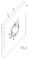
- Figure 5 shows a sectional view of an example of an electrical installation box assembly.
- an electrical installation box assembly for installation into an opening in a wall 30 of a structure comprises a fastening part 10 and a box case 20.
- the electrical installation box assembly is a retrofit electrical installation box assembly.
- the electrical installation box assembly is adapted for retrofitting into the opening in the wall 30.
- the fastening part 10 comprises a tubular side wall portion 11, which extends between a first end and a second end of the fastening part 10, and at least one flange portion 12 at the first end of the fastening part 10 extending radially from the side wall portion 11 of the fastening part 10.
- the examples shown in the figures comprise two collar-like flange portions 12 but the number and shape of the flange portion(s) can vary.
- the fastening part 10 comprises at least one flexibly mounted projection 13, 14 located at a distance from the at least one flange portion 12 and extending radially from the side wall portion 11 of the fastening part 10 in a resting position.
- the at least one flexibly mounted projection 13, 14 is adapted to engage the wall 30 in its resting position when the fastening part is inserted, with the second end thereof ahead, inside the opening in the wall from a first side 31 of the wall such that the at least one flange portion 12 is in contact with the first side of the wall.
- At least one 13 of the at least one flexibly mounted projection of the fastening part 10 is located at a first distance from the at least one flange portion 12 and adapted to move towards inside of the side wall portion 11 of the fastening part 10 during the insertion of the fastening part 10, with the second end (i.e.
- FIG. 1 shows an example of beak-like projections 13 in their resting position before the fastening part is inserted into an opening of the wall 30.
- Figures 2 to 4 show an example of the fastening part 10 pushed into an opening in the wall 30, from the first side 31 of the wall 30, such that the beak-like projections 13 have during insertion of the fastening part 10 flexed inside thus enabling the entering of the fastening part into the opening of the wall, which opening has a diameter which is essentially equal to or slightly greater than the outer diameter of the fastening part 10 such that the fastening part preferably firmly engages the opening.
- the projections 13 Upon reaching a fully inserted position of the fastening part 10 into the opening of the wall 30, the projections 13 have returned to their resting position and the flange portions 12 are resting essentially in contact with the first side 31 of the wall 30, as can be seen in Figures 4 and 5 .
- the wall 30 is sandwiched, i.e. gripped, between the flange portions 12 and the projections 13.
- the first distance between the at least one projection 13 of the fastening part 10 and the at least one flange portion 12 of the fastening part 10 is equal to or greater than a thickness of the wall 30.
- Said distance between the at least one projection 13 of the fastening part 10 and the at least one flange portion 12 of the fastening part 10 is preferably as close as possible to the thickness of the wall 30 into which the electrical installation box assembly is to be installed in order to achieve as secure fastening of the electrical installation box assembly into the wall 30 as possible.
- fastening part 10 comprises two or more flexibly mounted projections 13 of which some or all have a different distance to the flange portion 12 of the fastening part 10. This enables the same fastening part 10 to be used for walls 30 of different thicknesses while still achieving a secure fastening of the electrical installation box assembly into the wall 30.
- At least one 14 of said at least one flexibly mounted projection of the fastening part 10 is located at a second distance from the at least one flange portion 12 and adapted to engage, in its resting position, an interior edge of the opening of the wall 30, when the fastening 10 part is inserted, with the second end thereof ahead, inside the opening in the wall from the first side 31 of the wall such that the at least one flange portion 12 is in contact with the first side of the wall.
- projections 14 of the fastening part 10 which can engage the edge of the opening of the wall 30, when the fastening part 10 is fully inserted into the opening, which opening has a diameter which is essentially equal to or slightly greater than the outer diameter of the fastening part 10, are shown in Figures 1 and 4 .
- Such projections 14 preferably extend radially from the side wall portion 11 of the fastening part 10 less than the projections 13 of the fastening part.
- the second distance between the at least one projection 14 of the fastening part 10 and the at least one flange portion 12 of the fastening part is smaller than a thickness of the wall 30.
- projection 14 is at least partly left inside the opening of the wall 30, when the fastening 10 part is inserted therein thus gripping the interior edge of the opening of the wall 30.
- the number and shape of the projections 14 can vary and can comprise one or more peaks or a generally protruding uneven or roughened surface, for example.
- the box case 20 comprises a tubular side wall portion 21 extending between a first end and a second end of the box case 20, and a bottom wall portion 22 at the first end of the box case 20.
- an outer diameter of the side wall portion 21 of the box case 20 is equal to or smaller than an inner diameter of the side wall portion 11 of the fastening part 10 such that upon inserting the box case 20, with the first end (i.e. the end with the bottom wall portion 22) of the box case 20 ahead, into the fastening part 10, from the first end of the fastening part, the box case locks the at least one projection 13, 14 of the fastening part 10 into its resting position.
- Figures 3 to 5 show a situation in which the box case 20 is fully inserted into the fastening part 10.
- the tubular side wall portion 21 of the box case prevents the projections 13, 14 of the fastening part 10 from flexing inside thus effectively locking them into their resting positions.
- the electrical installation box assembly comprising the fastening part 10 and the box case 20 is fixed into the opening of the wall 30.
- the fastening part 10 in order to assemble the electrical installation box assembly comprising the fastening part 10 and the box case 20 into the opening of the wall, the fastening part 10 is firstly fully inserted into the opening of the wall 30 as described above. After that the box case is fully inserted into the fastening part 10. Upon assembling the electrical installation box assembly into the opening of the wall the at least one projection 13, 14 of the fastening part 10 may return to its resting position by itself after possibly flexing during the insertion of the fastening part 10 into the opening of the wall.
- the insertion of the box case 20 into the fastening part 10 preferably forces any such projections 13, 14 still in their flexed positions into their resting positions, and consequently locks all the projections 13, 14 of the fastening part 10 into their resting positions (i.e. non-flexed positions).
- the box case 20 comprises at least one flexibly mounted projection 23 extending radially from the side wall portion 21 of the box case 20 in a resting position and being adapted to move towards inside of the side wall portion 21 of the box case 20 during insertion of the box case 20 into the fastening part 10.
- the at least one flexibly mounted projection 23 is adapted to engage the fastening part 10, when the box case 20 is fully inserted into the fastening part 10, to prevent the box case 20 from moving out from the fastening part 10.
- Figures 1 and 2 show an example of a beak-like projection 23 in its resting position before the box case 20 is fully inserted into the fastening part 10.
- the projections 23 of the box case 20 have engaged the fastening part 10 thus locking the box case 20 inside the fastening part 10 and preventing the box case from sliding out of the fastening part.
- the at least one projection 23 of the box case is configured to be pressed into its flexed position towards inside of the side wall portion 21 of the box case 20 to enable the removal of the box case 20 from inside of the fastening part 10.
- the box case may shaped to include a groove 24 or an opening via which a tool, such as a screwdriver or the like, can be pushed against the projection 23 of the box case in order to push it into its flexed position thus enabling the possible disassembling of the electrical installation box assembly and the possible removal thereof from the opening of the wall 30.
- a tool such as a screwdriver or the like
- the fastening part 10 and the box case 20 each comprise at least one mating surface which engage or generally contact each other, when the box case 20 is fully inserted into the fastening part 10, to prevent the box case from moving further into the fastening part.
- the embodiments shown in Figure 1 show one mating surface 25 of the box case 20, which engages a corresponding mating surface (not visible in the Figure) of the fastening part 10, when the box case 20 is fully inserted into the fastening part 10. It should be noted that the number and shape of such mating surfaces of the box case 20 and the fastening part 10 may vary.
- the second end of the box case is essentially flush with the first end of the fastening part.
- the fastening part 10 when the fastening part 10 is fully inserted into the opening of the wall 30 from the first side of the wall and the box case 20 is fully inserted into the fastening part 10, both the second end of the box case and the first end of the fastening part are essentially flush with the first side of the wall and the box case extends away from the wall on the second side of the wall.
- the at least one projection 13 of the fastening part 10 is an integral part of the fastening part.
- the at least one projection 13 of the fastening part 10 can be made of the same material as the rest of the fastening part.
- the at least one projection 23 of the box case 20 is an integral part of the box case.
- the at least one projection 23 of the box case 10 can be made of the same material as the rest of the box case.
- the fastening part 10 and/or the box case 20 can be made of plastic material, for example. It is possible to manufacture both the fastening part 10 and the box case 20 with single injection moulding processes, for example.
- cross profiles of the tubular side wall portions 11, 21 of the fastening part 10 and the box case 20 are at least partly circular.
- the cross profiles of the tubular side wall portions of the fastening part and the box case are mainly circular.
- the examples of Figures 1 to 5 show examples in which the cross profiles of the tubular side wall portions 11, 21 of the fastening part 10 and the box case 20, when see along a longitudinal axis of the tubular wall portions 11, 21, are mainly circular such that they comprise flat portions on both sides.
- the side wall portion 21 and/or the bottom wall portion 22 of the box case 20 comprise at least one aperture and/or at least one knockout arrangement 26.
- the examples of Figures 1 to 5 show examples of such knockout arrangements 26, which enable the creation of knockout holes for introducing electric conductors into the box case 20 through the side wall portion 21 and/or the bottom wall portion 22 of the box case 20, for example.
- the number and shape of such apertures or knockout arrangements 26 may vary.
- the box case 20 is adapted to house one or more interconnections of electrical conductors and/or one or more electrical components or devices (not shown in the figures).
- the box case may comprise, in addition to the possible apertures or knockout arrangements 26, suitable parts into which interconnections of electrical conductors and/or one or more electrical components or devices can be fitted.
- the box case 20 comprises screw holes 27 at least some of which can be used to fasten electrical components or devices into the box case 20.
- the box case 20 is adapted to receive a cover (not shown in the figures) on the second end of the box case.
- the box case may comprise suitable parts for enabling a possible cover to be fastened to the box case.
- the box case 20 comprises screw holes 27 at least some of which can be used to attach a cover on the end of the box case 20.
Landscapes
- Engineering & Computer Science (AREA)
- Architecture (AREA)
- Civil Engineering (AREA)
- Structural Engineering (AREA)
- Connection Or Junction Boxes (AREA)
Abstract
Description
- The invention relates to an electrical installation box assembly and more specifically to an electrical installation box assembly for installation into an opening in a wall of a structure.
- In electrical installation electrical installation boxes, such as junction boxes or mounting boxes, are used to house interconnections of electrical conductors and electrical components or devices, for example. An electrical installation box may be installed in a wall of a structure, such as a building, a vehicle or a vessel, for example. The wall, or a wall panel thereof, may be provided with an opening into which the electrical installation box may be inserted especially in case of flush mounting. In this case the electrical installation box is mounted essentially flush with a first side of the wall and the electrical installation box then extends away from a second side of the wall, for example, between a space between two walls.
- In case of an installation of an electrical installation box into a wall of an existing structure, the second side of the wall is typically not readily accessible and the electrical installation box needs to be installed, or retrofitted, into the opening in the wall from the first side of the wall typically by using a specific retrofit electrical installation box which is suitable for installation into the opening in the wall from the first side of the wall.
- In case of such retrofitting of the electrical installation box from the first side of the wall, when the second side of the wall is not easily accessible, the fastening of the electrical installation box to the wall cannot be performed from the second side of the wall. In this case the fastening of the electrical installation box to the wall may be performed from the first side of the wall after insertion of the electrical installation box into the opening in the wall from the first side of the wall by using screws and possible counterparts thereof, for example.
- A problem with the above-described solution is that installation by using screws and possible counterparts thereof is time-consuming and also the number of components and tools required for the installation may be high.
- The object of the invention is thus to provide an apparatus so as to solve or at least alleviate the above problem. The object of the invention is achieved with an electrical installation box assembly that is characterized by what is stated in the independent claim. Preferred embodiments of the invention are described in the dependent claims.
- The invention is based on the idea of providing the electrical installation box assembly with a fastening part comprising at least one flexibly mounted projection and at least one flange portion such that the projection is adapted to engage the wall in its resting position when the fastening part is inserted inside an opening in a wall such that the at least one flange portion is in contact with the wall, and with a box case which locks the at least one projection of the fastening part in its resting position upon insertion of the box case into the fastening part.
- An advantage of the solution according to the invention is that it enables a retrofit installation of the electrical installation box into an opening in the wall to be carried out in a simple and fast manner without any additional components.
- In the following, the invention will be described in more detail in connection with preferred embodiments with reference to the accompanying drawing, in which
-
Figure 1 shows a perspective view of an example of an electrical installation box assembly according to an embodiment; -
Figure 2 shows a perspective view of an example of an electrical installation box assembly according to an embodiment; -
Figure 3 shows a perspective view of an example of an electrical installation box assembly according to an embodiment; -
Figure 4 shows a perspective view of an example of an electrical installation box assembly according to an embodiment; and -
Figure 5 shows a sectional view of an example of an electrical installation box assembly according to an embodiment. -
Figure 1 shows an example of an electrical installation box assembly according to an embodiment.Figure 2 shows an example of an electrical installation box assembly corresponding toFigure 1 , which is partly installed in a wall.Figure 3 shows an example of an electrical installation box assembly corresponding toFigure 1 , which is fully installed in a wall and seen from a first side of the wall.Figure 4 shows an example of an electrical installation box assembly corresponding toFigure 1 , which is fully installed in a wall and seen from a second side of the wall.Figure 5 shows a sectional view of an example of an electrical installation box assembly. According to an embodiment, an electrical installation box assembly for installation into an opening in awall 30 of a structure comprises a fasteningpart 10 and abox case 20. According to an embodiment, the electrical installation box assembly is a retrofit electrical installation box assembly. In other words, the electrical installation box assembly is adapted for retrofitting into the opening in thewall 30. - According to an embodiment, the
fastening part 10 comprises a tubularside wall portion 11, which extends between a first end and a second end of thefastening part 10, and at least oneflange portion 12 at the first end of the fasteningpart 10 extending radially from theside wall portion 11 of thefastening part 10. The examples shown in the figures comprise two collar-like flange portions 12 but the number and shape of the flange portion(s) can vary. Moreover, the fasteningpart 10 comprises at least one flexibly mountedprojection flange portion 12 and extending radially from theside wall portion 11 of the fasteningpart 10 in a resting position. According to an embodiment, the at least one flexibly mountedprojection wall 30 in its resting position when the fastening part is inserted, with the second end thereof ahead, inside the opening in the wall from a first side 31 of the wall such that the at least oneflange portion 12 is in contact with the first side of the wall. - According to an embodiment, at least one 13 of the at least one flexibly mounted projection of the fastening
part 10 is located at a first distance from the at least oneflange portion 12 and adapted to move towards inside of theside wall portion 11 of the fasteningpart 10 during the insertion of the fasteningpart 10, with the second end (i.e. the opposite end to the end comprising the at least one flange portion 12) thereof ahead, into the opening in thewall 30 from the first side 31 of the wall, and to return to its resting position upon entering asecond side 32 of the wall, when the fasteningpart 10 is inserted inside the opening in thewall 30 such that the at least oneflange portion 12 is in contact with the first side 31 of the wall, thus engaging the wall such that thewall 30 is sandwiched between the at least oneflange portion 12 and the at least oneprojection 13.Figure 1 shows an example of beak-like projections 13 in their resting position before the fastening part is inserted into an opening of thewall 30.Figures 2 to 4 show an example of thefastening part 10 pushed into an opening in thewall 30, from the first side 31 of thewall 30, such that the beak-like projections 13 have during insertion of the fasteningpart 10 flexed inside thus enabling the entering of the fastening part into the opening of the wall, which opening has a diameter which is essentially equal to or slightly greater than the outer diameter of the fasteningpart 10 such that the fastening part preferably firmly engages the opening. Upon reaching a fully inserted position of the fasteningpart 10 into the opening of thewall 30, theprojections 13 have returned to their resting position and theflange portions 12 are resting essentially in contact with the first side 31 of thewall 30, as can be seen inFigures 4 and5 . As a result, thewall 30 is sandwiched, i.e. gripped, between theflange portions 12 and theprojections 13. According to an embodiment, the first distance between the at least oneprojection 13 of the fasteningpart 10 and the at least oneflange portion 12 of the fasteningpart 10 is equal to or greater than a thickness of thewall 30. Said distance between the at least oneprojection 13 of the fasteningpart 10 and the at least oneflange portion 12 of thefastening part 10 is preferably as close as possible to the thickness of thewall 30 into which the electrical installation box assembly is to be installed in order to achieve as secure fastening of the electrical installation box assembly into thewall 30 as possible. It is also possible that fasteningpart 10 comprises two or more flexibly mountedprojections 13 of which some or all have a different distance to theflange portion 12 of thefastening part 10. This enables thesame fastening part 10 to be used forwalls 30 of different thicknesses while still achieving a secure fastening of the electrical installation box assembly into thewall 30. - According to an embodiment, at least one 14 of said at least one flexibly mounted projection of the fastening
part 10 is located at a second distance from the at least oneflange portion 12 and adapted to engage, in its resting position, an interior edge of the opening of thewall 30, when thefastening 10 part is inserted, with the second end thereof ahead, inside the opening in the wall from the first side 31 of the wall such that the at least oneflange portion 12 is in contact with the first side of the wall. Examples ofpossible projections 14 of the fasteningpart 10, which can engage the edge of the opening of thewall 30, when the fasteningpart 10 is fully inserted into the opening, which opening has a diameter which is essentially equal to or slightly greater than the outer diameter of the fasteningpart 10, are shown inFigures 1 and4 .Such projections 14 preferably extend radially from theside wall portion 11 of the fasteningpart 10 less than theprojections 13 of the fastening part. According to an embodiment, the second distance between the at least oneprojection 14 of the fasteningpart 10 and the at least oneflange portion 12 of the fastening part is smaller than a thickness of thewall 30. As shown inFigure 4 ,projection 14 is at least partly left inside the opening of thewall 30, when the fastening 10 part is inserted therein thus gripping the interior edge of the opening of thewall 30. The number and shape of theprojections 14 can vary and can comprise one or more peaks or a generally protruding uneven or roughened surface, for example. - According to an embodiment, the
box case 20 comprises a tubularside wall portion 21 extending between a first end and a second end of thebox case 20, and abottom wall portion 22 at the first end of thebox case 20. Preferably an outer diameter of theside wall portion 21 of thebox case 20 is equal to or smaller than an inner diameter of theside wall portion 11 of the fasteningpart 10 such that upon inserting thebox case 20, with the first end (i.e. the end with the bottom wall portion 22) of thebox case 20 ahead, into the fasteningpart 10, from the first end of the fastening part, the box case locks the at least oneprojection part 10 into its resting position.Figures 3 to 5 show a situation in which thebox case 20 is fully inserted into the fasteningpart 10. When thebox case 20 is fully inserted into the fasteningpart 10, the tubularside wall portion 21 of the box case prevents theprojections part 10 from flexing inside thus effectively locking them into their resting positions. As a result, the electrical installation box assembly comprising the fasteningpart 10 and thebox case 20 is fixed into the opening of thewall 30. - Thus, according to an embodiment, in order to assemble the electrical installation box assembly comprising the fastening
part 10 and thebox case 20 into the opening of the wall, the fasteningpart 10 is firstly fully inserted into the opening of thewall 30 as described above. After that the box case is fully inserted into the fasteningpart 10. Upon assembling the electrical installation box assembly into the opening of the wall the at least oneprojection part 10 may return to its resting position by itself after possibly flexing during the insertion of the fasteningpart 10 into the opening of the wall. If the projection(s) 13, 14, or some of them, do not return to their resting position by themselves, then the insertion of thebox case 20 into the fasteningpart 10 preferably forces anysuch projections projections part 10 into their resting positions (i.e. non-flexed positions). - According to an embodiment, the
box case 20 comprises at least one flexibly mountedprojection 23 extending radially from theside wall portion 21 of thebox case 20 in a resting position and being adapted to move towards inside of theside wall portion 21 of thebox case 20 during insertion of thebox case 20 into the fasteningpart 10. Moreover, the at least one flexibly mountedprojection 23 is adapted to engage thefastening part 10, when thebox case 20 is fully inserted into thefastening part 10, to prevent thebox case 20 from moving out from thefastening part 10.Figures 1 and2 show an example of a beak-like projection 23 in its resting position before thebox case 20 is fully inserted into the fasteningpart 10. As seen infigures 4 and5 , when thebox case 20 is fully inserted into the fasteningpart 10, theprojections 23 of thebox case 20 have engaged the fasteningpart 10 thus locking thebox case 20 inside the fasteningpart 10 and preventing the box case from sliding out of the fastening part. According to an embodiment, the at least oneprojection 23 of the box case is configured to be pressed into its flexed position towards inside of theside wall portion 21 of thebox case 20 to enable the removal of thebox case 20 from inside of thefastening part 10. For this purpose the box case may shaped to include agroove 24 or an opening via which a tool, such as a screwdriver or the like, can be pushed against theprojection 23 of the box case in order to push it into its flexed position thus enabling the possible disassembling of the electrical installation box assembly and the possible removal thereof from the opening of thewall 30. - According to an embodiment, the
fastening part 10 and thebox case 20 each comprise at least one mating surface which engage or generally contact each other, when thebox case 20 is fully inserted into thefastening part 10, to prevent the box case from moving further into the fastening part. As an example, the embodiments shown inFigure 1 show onemating surface 25 of thebox case 20, which engages a corresponding mating surface (not visible in the Figure) of thefastening part 10, when thebox case 20 is fully inserted into thefastening part 10. It should be noted that the number and shape of such mating surfaces of thebox case 20 and thefastening part 10 may vary. - According to an embodiment, when the
box case 20 is fully inserted into thefastening part 10, the second end of the box case is essentially flush with the first end of the fastening part. This can be seen in the examples ofFigures 3 and5 . Moreover, according to an embodiment, when thefastening part 10 is fully inserted into the opening of thewall 30 from the first side of the wall and thebox case 20 is fully inserted into thefastening part 10, both the second end of the box case and the first end of the fastening part are essentially flush with the first side of the wall and the box case extends away from the wall on the second side of the wall. - According to an embodiment, the at least one
projection 13 of thefastening part 10 is an integral part of the fastening part. Thus, the at least oneprojection 13 of thefastening part 10 can be made of the same material as the rest of the fastening part. In a similar manner, according to an embodiment, the at least oneprojection 23 of thebox case 20 is an integral part of the box case. Thus, the at least oneprojection 23 of thebox case 10 can be made of the same material as the rest of the box case. - According to an embodiment, the
fastening part 10 and/or thebox case 20 can be made of plastic material, for example. It is possible to manufacture both thefastening part 10 and thebox case 20 with single injection moulding processes, for example. - According to an embodiment, cross profiles of the tubular
side wall portions fastening part 10 and thebox case 20 are at least partly circular. According to an embodiment, the cross profiles of the tubular side wall portions of the fastening part and the box case are mainly circular. The examples ofFigures 1 to 5 show examples in which the cross profiles of the tubularside wall portions fastening part 10 and thebox case 20, when see along a longitudinal axis of thetubular wall portions - According to an embodiment, the
side wall portion 21 and/or thebottom wall portion 22 of thebox case 20 comprise at least one aperture and/or at least oneknockout arrangement 26. The examples ofFigures 1 to 5 show examples ofsuch knockout arrangements 26, which enable the creation of knockout holes for introducing electric conductors into thebox case 20 through theside wall portion 21 and/or thebottom wall portion 22 of thebox case 20, for example. The number and shape of such apertures orknockout arrangements 26 may vary. According to an embodiment, thebox case 20 is adapted to house one or more interconnections of electrical conductors and/or one or more electrical components or devices (not shown in the figures). For this purpose the box case may comprise, in addition to the possible apertures orknockout arrangements 26, suitable parts into which interconnections of electrical conductors and/or one or more electrical components or devices can be fitted. In the examples ofFigures 1 ,2 and5 thebox case 20 comprises screw holes 27 at least some of which can be used to fasten electrical components or devices into thebox case 20. - According to an embodiment, the
box case 20 is adapted to receive a cover (not shown in the figures) on the second end of the box case. For this purpose the box case may comprise suitable parts for enabling a possible cover to be fastened to the box case. In the examples ofFigures 1 ,2 and5 thebox case 20 comprises screw holes 27 at least some of which can be used to attach a cover on the end of thebox case 20. - It is obvious to a person skilled in the art that as technology advances, the basic idea of the invention can be implemented in a variety of ways. Consequently, the invention and its embodiments are not restricted to the above examples, but can vary within the scope of the claims.
Claims (15)
- An electrical installation box assembly for installation into an opening in a wall of a structure, comprising:a fastening part (10) comprising a tubular side wall portion (11) extending between a first end and a second end of the fastening part, and at least one flange portion (12) at the first end of the fastening part extending radially from the side wall portion of the fastening part, and at least one flexibly mounted projection (13, 14) located at a distance from the at least one flange portion and extending radially from the side wall portion of the fastening part in a resting position and being adapted to engage the wall (30) in its resting position when the fastening part is inserted, with the second end thereof ahead, inside the opening in the wall from a first side (31) of the wall such that the at least one flange portion is in contact with the first side of the wall; anda box case (20) comprising a tubular side wall portion (21) extending between a first end and a second end of the box case, and a bottom wall portion (22) at the first end of the box case, wherein an outer diameter of the side wall portion of the box case is equal to or smaller than an inner diameter of the side wall portion of the fastening part such that upon inserting the box case, with the first end of the box case ahead, into the fastening part, from the first end of the fastening part, the box case locks the at least one projection of the fastening part into its resting position.
- An electrical installation box assembly as claimed in claim 1, wherein at least one (13) of said at least one flexibly mounted projection of the fastening part (10) is located at a first distance from the at least one flange portion (12) and adapted to move towards inside of the side wall portion (11) of the fastening part during the insertion of the fastening part, with the second end thereof ahead, into the opening in the wall (30) from the first side (31) of the wall, and to return to its resting position upon entering a second side (32) of the wall, when the fastening part is inserted inside the opening in the wall such that the at least one flange portion is in contact with the first side of the wall, thus engaging the wall such that the wall is sandwiched between the at least one flange portion and the at least one projection.
- An electrical installation box assembly as claimed in claim 2, wherein the first distance between the at least one projection (13) of the fastening part (10) and the at least one flange portion (12) of the fastening part is equal to or greater than a thickness of the wall (30).
- An electrical installation box assembly as claimed in claim 1, 2 or 3, wherein at least one (14) of said at least one flexibly mounted projection of the fastening part (10) is located at a second distance from the at least one flange portion (12) and adapted to engage, in its resting position, an interior edge of the opening of the wall, when the fastening part is inserted, with the second end thereof ahead, inside the opening in the wall from the first side of the wall such that the at least one flange portion is in contact with the first side of the wall.
- An electrical installation box assembly as claimed in claim 4, wherein the second distance between the at least one projection (14) of the fastening part (10) and the at least one flange portion (12) of the fastening part is smaller than a thickness of the wall (30).
- An electrical installation box assembly as claimed in any one of claims 1 to 5, wherein the box case (20) comprises at least one flexibly mounted projection (23) extending radially from the side wall portion (21) of the box case in a resting position and being adapted to move towards inside of the side wall portion of the box case during insertion of the box case into the fastening part (10), and to engage the fastening part, when the box case is fully inserted into the fastening part, to prevent the box case from moving out from the fastening part.
- An electrical installation box assembly as claimed in any one of claims 1 to 6, wherein the fastening part (10) and the box case (20) each comprise at least one mating surface (25) which engage each other, when the box case is fully inserted into the fastening part, to prevent the box case from moving further into the fastening part.
- An electrical installation box assembly as claimed in claim 7, wherein, when the box case (20) is fully inserted into the fastening part (10), the second end of the box case is essentially flush with the first end of the fastening part.
- An electrical installation box assembly as claimed in claim 8, wherein, when the fastening part (10) is fully inserted into the opening of the wall (30) from the first side of the wall and the box case (20) is fully inserted into the fastening part, both the second end of the box case and the first end of the fastening part are essentially flush with the first side of the wall and the box case extends away from the wall on the second side of the wall.
- An electrical installation box assembly as claimed in any one of claims 1 to 9, wherein the at least one projection (13, 14) of the fastening part (10) is an integral part of the fastening part.
- An electrical installation box assembly as claimed in any one of claims 1 to 10, wherein the at least one projection (23) of the box case (20) is an integral part of the box case.
- An electrical installation box assembly as claimed in any one of claims 1 to 11, wherein the fastening part (10) and/or the box case (20) are made of plastic material.
- An electrical installation box assembly as claimed in any one of claims 1 to 12, wherein cross profiles of the tubular side wall portions (11, 21) of the fastening part (10) and the box case (20) are at least partly circular.
- An electrical installation box assembly as claimed in claim 13, wherein the cross profiles of the tubular side wall portions (11, 21) of the fastening part (10) and the box case (20) are mainly circular.
- An electrical installation box assembly as claimed in any one of claims 1 to 14, wherein the side wall portion (21) and/or the bottom wall portion (22) of the box case comprise at least one aperture and/or at least one knockout arrangement (26).
Priority Applications (1)
| Application Number | Priority Date | Filing Date | Title |
|---|---|---|---|
| EP15155857.4A EP3059822B1 (en) | 2015-02-20 | 2015-02-20 | Electrical installation box assembly |
Applications Claiming Priority (1)
| Application Number | Priority Date | Filing Date | Title |
|---|---|---|---|
| EP15155857.4A EP3059822B1 (en) | 2015-02-20 | 2015-02-20 | Electrical installation box assembly |
Publications (2)
| Publication Number | Publication Date |
|---|---|
| EP3059822A1 true EP3059822A1 (en) | 2016-08-24 |
| EP3059822B1 EP3059822B1 (en) | 2021-11-03 |
Family
ID=52477714
Family Applications (1)
| Application Number | Title | Priority Date | Filing Date |
|---|---|---|---|
| EP15155857.4A Active EP3059822B1 (en) | 2015-02-20 | 2015-02-20 | Electrical installation box assembly |
Country Status (1)
| Country | Link |
|---|---|
| EP (1) | EP3059822B1 (en) |
Cited By (2)
| Publication number | Priority date | Publication date | Assignee | Title |
|---|---|---|---|---|
| WO2018060338A1 (en) * | 2016-09-29 | 2018-04-05 | FILUXX-Systems GmbH | Flush-mount box for lamp connections |
| EP3355425A1 (en) * | 2017-01-31 | 2018-08-01 | ABB Schweiz AG | Assembly of an installation box and electric installation material, installation box and airtight insert |
Citations (4)
| Publication number | Priority date | Publication date | Assignee | Title |
|---|---|---|---|---|
| WO1990012433A1 (en) * | 1989-03-31 | 1990-10-18 | Johnson Service Company | Wall mouting plate |
| WO2003081054A1 (en) * | 2002-03-27 | 2003-10-02 | Daxtor Aps | Expansion unit |
| FR3000308A1 (en) * | 2012-12-20 | 2014-06-27 | Legrand France | REMOVABLE ELECTRICAL EQUIPMENT MODULE, ELECTRIC BOX HAVING SUCH AN APPARATUS MODULE, AND METHOD OF REPLACING SUCH A MODULE OF APPARATUS |
| EP2822120A1 (en) * | 2013-07-05 | 2015-01-07 | ABB Oy | Mounting box |
Family Cites Families (4)
| Publication number | Priority date | Publication date | Assignee | Title |
|---|---|---|---|---|
| US3620401A (en) * | 1970-05-11 | 1971-11-16 | Markstone Mfg Co | Recessed lighting fixture including mounting clamp means |
| DE2312605A1 (en) * | 1973-03-14 | 1974-09-19 | Paul Dahl | TWO-PIECE INSTALLATION BOX |
| FR3000309B1 (en) * | 2012-12-20 | 2015-01-09 | Legrand France | AUTOMATIC FASTENING RECESSED ELECTRICAL BOX ON A WALL |
| FR3017498B1 (en) * | 2014-02-07 | 2016-02-19 | Legrand France | ELECTRICAL DEVICE WITH RECOVERY |
-
2015
- 2015-02-20 EP EP15155857.4A patent/EP3059822B1/en active Active
Patent Citations (4)
| Publication number | Priority date | Publication date | Assignee | Title |
|---|---|---|---|---|
| WO1990012433A1 (en) * | 1989-03-31 | 1990-10-18 | Johnson Service Company | Wall mouting plate |
| WO2003081054A1 (en) * | 2002-03-27 | 2003-10-02 | Daxtor Aps | Expansion unit |
| FR3000308A1 (en) * | 2012-12-20 | 2014-06-27 | Legrand France | REMOVABLE ELECTRICAL EQUIPMENT MODULE, ELECTRIC BOX HAVING SUCH AN APPARATUS MODULE, AND METHOD OF REPLACING SUCH A MODULE OF APPARATUS |
| EP2822120A1 (en) * | 2013-07-05 | 2015-01-07 | ABB Oy | Mounting box |
Cited By (2)
| Publication number | Priority date | Publication date | Assignee | Title |
|---|---|---|---|---|
| WO2018060338A1 (en) * | 2016-09-29 | 2018-04-05 | FILUXX-Systems GmbH | Flush-mount box for lamp connections |
| EP3355425A1 (en) * | 2017-01-31 | 2018-08-01 | ABB Schweiz AG | Assembly of an installation box and electric installation material, installation box and airtight insert |
Also Published As
| Publication number | Publication date |
|---|---|
| EP3059822B1 (en) | 2021-11-03 |
Similar Documents
| Publication | Publication Date | Title |
|---|---|---|
| US9048640B2 (en) | Electrical box and sleeve assembly | |
| US8748744B2 (en) | Electrical box extender assembly | |
| KR101921098B1 (en) | Fastening assembly for a built-in refrigerator on a side wall of a furniture body | |
| EP3276756B1 (en) | A connector assembly with a connector, a latch member and a panel | |
| EP1914847A2 (en) | Cable connector for vehicle door | |
| US9341292B2 (en) | Inside corner pull elbow fitting | |
| US9705295B1 (en) | Slip conduit connector and system and method of installing electrical conduit with a slip conduit connector | |
| US20160226232A1 (en) | Electrical box and sleeve assembly | |
| US8686287B1 (en) | Surface mount electrical box for shallow wall cavities | |
| US10263399B2 (en) | Multiple latching feet for electrical connector assembly | |
| EP3059822A1 (en) | Electrical installation box assembly | |
| US20170063062A1 (en) | Floor box assembly with retainer | |
| US7342173B1 (en) | Multi-directional-port junction box | |
| US20200181952A1 (en) | Motor vehicle handle assembly | |
| KR101179851B1 (en) | Electric wiring box | |
| US20160141852A1 (en) | Self-aligning box and sleeve assembly | |
| US10215207B2 (en) | Support member | |
| US8445778B2 (en) | Cable entry device for wiring boxes | |
| US7488891B1 (en) | Fixture or outlet box with selectable fastening points | |
| EP2648296B1 (en) | Modular electrical device for switches, sockets and other electrical components to be applied to a wall. | |
| US10742012B2 (en) | Screw less cover plate for electrical fixtures | |
| EP3528354B1 (en) | Flush electrical box | |
| US20140256177A1 (en) | Magnetic Screw Guide For Distribution Block Assembly | |
| US9496694B1 (en) | Easy insertion electrical connector | |
| CN107925231B (en) | Cabinets designed to be embedded in walls |
Legal Events
| Date | Code | Title | Description |
|---|---|---|---|
| PUAI | Public reference made under article 153(3) epc to a published international application that has entered the european phase |
Free format text: ORIGINAL CODE: 0009012 |
|
| AK | Designated contracting states |
Kind code of ref document: A1 Designated state(s): AL AT BE BG CH CY CZ DE DK EE ES FI FR GB GR HR HU IE IS IT LI LT LU LV MC MK MT NL NO PL PT RO RS SE SI SK SM TR |
|
| AX | Request for extension of the european patent |
Extension state: BA ME |
|
| STAA | Information on the status of an ep patent application or granted ep patent |
Free format text: STATUS: REQUEST FOR EXAMINATION WAS MADE |
|
| 17P | Request for examination filed |
Effective date: 20161123 |
|
| RBV | Designated contracting states (corrected) |
Designated state(s): AL AT BE BG CH CY CZ DE DK EE ES FI FR GB GR HR HU IE IS IT LI LT LU LV MC MK MT NL NO PL PT RO RS SE SI SK SM TR |
|
| STAA | Information on the status of an ep patent application or granted ep patent |
Free format text: STATUS: EXAMINATION IS IN PROGRESS |
|
| 17Q | First examination report despatched |
Effective date: 20170606 |
|
| RAP1 | Party data changed (applicant data changed or rights of an application transferred) |
Owner name: ABB SCHWEIZ AG |
|
| RIC1 | Information provided on ipc code assigned before grant |
Ipc: H02G 3/08 20060101ALN20200129BHEP Ipc: H02G 3/12 20060101AFI20200129BHEP |
|
| RIC1 | Information provided on ipc code assigned before grant |
Ipc: H02G 3/12 20060101AFI20200203BHEP Ipc: H02G 3/08 20060101ALN20200203BHEP |
|
| GRAP | Despatch of communication of intention to grant a patent |
Free format text: ORIGINAL CODE: EPIDOSNIGR1 |
|
| STAA | Information on the status of an ep patent application or granted ep patent |
Free format text: STATUS: GRANT OF PATENT IS INTENDED |
|
| RIC1 | Information provided on ipc code assigned before grant |
Ipc: H02G 3/08 20060101ALN20210504BHEP Ipc: H02G 3/12 20060101AFI20210504BHEP |
|
| INTG | Intention to grant announced |
Effective date: 20210526 |
|
| RAP3 | Party data changed (applicant data changed or rights of an application transferred) |
Owner name: ABB SCHWEIZ AG |
|
| GRAS | Grant fee paid |
Free format text: ORIGINAL CODE: EPIDOSNIGR3 |
|
| GRAA | (expected) grant |
Free format text: ORIGINAL CODE: 0009210 |
|
| STAA | Information on the status of an ep patent application or granted ep patent |
Free format text: STATUS: THE PATENT HAS BEEN GRANTED |
|
| AK | Designated contracting states |
Kind code of ref document: B1 Designated state(s): AL AT BE BG CH CY CZ DE DK EE ES FI FR GB GR HR HU IE IS IT LI LT LU LV MC MK MT NL NO PL PT RO RS SE SI SK SM TR |
|
| REG | Reference to a national code |
Ref country code: GB Ref legal event code: FG4D |
|
| REG | Reference to a national code |
Ref country code: AT Ref legal event code: REF Ref document number: 1444845 Country of ref document: AT Kind code of ref document: T Effective date: 20211115 Ref country code: CH Ref legal event code: EP |
|
| REG | Reference to a national code |
Ref country code: IE Ref legal event code: FG4D |
|
| REG | Reference to a national code |
Ref country code: DE Ref legal event code: R096 Ref document number: 602015074611 Country of ref document: DE |
|
| REG | Reference to a national code |
Ref country code: FI Ref legal event code: FGE |
|
| REG | Reference to a national code |
Ref country code: NO Ref legal event code: T2 Effective date: 20211103 |
|
| REG | Reference to a national code |
Ref country code: SE Ref legal event code: TRGR |
|
| REG | Reference to a national code |
Ref country code: LT Ref legal event code: MG9D |
|
| REG | Reference to a national code |
Ref country code: NL Ref legal event code: MP Effective date: 20211103 |
|
| REG | Reference to a national code |
Ref country code: AT Ref legal event code: MK05 Ref document number: 1444845 Country of ref document: AT Kind code of ref document: T Effective date: 20211103 |
|
| PG25 | Lapsed in a contracting state [announced via postgrant information from national office to epo] |
Ref country code: RS Free format text: LAPSE BECAUSE OF FAILURE TO SUBMIT A TRANSLATION OF THE DESCRIPTION OR TO PAY THE FEE WITHIN THE PRESCRIBED TIME-LIMIT Effective date: 20211103 Ref country code: LT Free format text: LAPSE BECAUSE OF FAILURE TO SUBMIT A TRANSLATION OF THE DESCRIPTION OR TO PAY THE FEE WITHIN THE PRESCRIBED TIME-LIMIT Effective date: 20211103 Ref country code: BG Free format text: LAPSE BECAUSE OF FAILURE TO SUBMIT A TRANSLATION OF THE DESCRIPTION OR TO PAY THE FEE WITHIN THE PRESCRIBED TIME-LIMIT Effective date: 20220203 Ref country code: AT Free format text: LAPSE BECAUSE OF FAILURE TO SUBMIT A TRANSLATION OF THE DESCRIPTION OR TO PAY THE FEE WITHIN THE PRESCRIBED TIME-LIMIT Effective date: 20211103 |
|
| PG25 | Lapsed in a contracting state [announced via postgrant information from national office to epo] |
Ref country code: IS Free format text: LAPSE BECAUSE OF FAILURE TO SUBMIT A TRANSLATION OF THE DESCRIPTION OR TO PAY THE FEE WITHIN THE PRESCRIBED TIME-LIMIT Effective date: 20220303 Ref country code: PT Free format text: LAPSE BECAUSE OF FAILURE TO SUBMIT A TRANSLATION OF THE DESCRIPTION OR TO PAY THE FEE WITHIN THE PRESCRIBED TIME-LIMIT Effective date: 20220303 Ref country code: PL Free format text: LAPSE BECAUSE OF FAILURE TO SUBMIT A TRANSLATION OF THE DESCRIPTION OR TO PAY THE FEE WITHIN THE PRESCRIBED TIME-LIMIT Effective date: 20211103 Ref country code: NL Free format text: LAPSE BECAUSE OF FAILURE TO SUBMIT A TRANSLATION OF THE DESCRIPTION OR TO PAY THE FEE WITHIN THE PRESCRIBED TIME-LIMIT Effective date: 20211103 Ref country code: LV Free format text: LAPSE BECAUSE OF FAILURE TO SUBMIT A TRANSLATION OF THE DESCRIPTION OR TO PAY THE FEE WITHIN THE PRESCRIBED TIME-LIMIT Effective date: 20211103 Ref country code: HR Free format text: LAPSE BECAUSE OF FAILURE TO SUBMIT A TRANSLATION OF THE DESCRIPTION OR TO PAY THE FEE WITHIN THE PRESCRIBED TIME-LIMIT Effective date: 20211103 Ref country code: GR Free format text: LAPSE BECAUSE OF FAILURE TO SUBMIT A TRANSLATION OF THE DESCRIPTION OR TO PAY THE FEE WITHIN THE PRESCRIBED TIME-LIMIT Effective date: 20220204 Ref country code: ES Free format text: LAPSE BECAUSE OF FAILURE TO SUBMIT A TRANSLATION OF THE DESCRIPTION OR TO PAY THE FEE WITHIN THE PRESCRIBED TIME-LIMIT Effective date: 20211103 |
|
| PG25 | Lapsed in a contracting state [announced via postgrant information from national office to epo] |
Ref country code: SM Free format text: LAPSE BECAUSE OF FAILURE TO SUBMIT A TRANSLATION OF THE DESCRIPTION OR TO PAY THE FEE WITHIN THE PRESCRIBED TIME-LIMIT Effective date: 20211103 Ref country code: SK Free format text: LAPSE BECAUSE OF FAILURE TO SUBMIT A TRANSLATION OF THE DESCRIPTION OR TO PAY THE FEE WITHIN THE PRESCRIBED TIME-LIMIT Effective date: 20211103 Ref country code: RO Free format text: LAPSE BECAUSE OF FAILURE TO SUBMIT A TRANSLATION OF THE DESCRIPTION OR TO PAY THE FEE WITHIN THE PRESCRIBED TIME-LIMIT Effective date: 20211103 Ref country code: EE Free format text: LAPSE BECAUSE OF FAILURE TO SUBMIT A TRANSLATION OF THE DESCRIPTION OR TO PAY THE FEE WITHIN THE PRESCRIBED TIME-LIMIT Effective date: 20211103 Ref country code: DK Free format text: LAPSE BECAUSE OF FAILURE TO SUBMIT A TRANSLATION OF THE DESCRIPTION OR TO PAY THE FEE WITHIN THE PRESCRIBED TIME-LIMIT Effective date: 20211103 Ref country code: CZ Free format text: LAPSE BECAUSE OF FAILURE TO SUBMIT A TRANSLATION OF THE DESCRIPTION OR TO PAY THE FEE WITHIN THE PRESCRIBED TIME-LIMIT Effective date: 20211103 |
|
| REG | Reference to a national code |
Ref country code: DE Ref legal event code: R097 Ref document number: 602015074611 Country of ref document: DE |
|
| REG | Reference to a national code |
Ref country code: DE Ref legal event code: R119 Ref document number: 602015074611 Country of ref document: DE |
|
| PLBE | No opposition filed within time limit |
Free format text: ORIGINAL CODE: 0009261 |
|
| STAA | Information on the status of an ep patent application or granted ep patent |
Free format text: STATUS: NO OPPOSITION FILED WITHIN TIME LIMIT |
|
| PG25 | Lapsed in a contracting state [announced via postgrant information from national office to epo] |
Ref country code: MC Free format text: LAPSE BECAUSE OF FAILURE TO SUBMIT A TRANSLATION OF THE DESCRIPTION OR TO PAY THE FEE WITHIN THE PRESCRIBED TIME-LIMIT Effective date: 20211103 |
|
| 26N | No opposition filed |
Effective date: 20220804 |
|
| REG | Reference to a national code |
Ref country code: CH Ref legal event code: PL |
|
| REG | Reference to a national code |
Ref country code: BE Ref legal event code: MM Effective date: 20220228 |
|
| GBPC | Gb: european patent ceased through non-payment of renewal fee |
Effective date: 20220220 |
|
| PG25 | Lapsed in a contracting state [announced via postgrant information from national office to epo] |
Ref country code: LU Free format text: LAPSE BECAUSE OF NON-PAYMENT OF DUE FEES Effective date: 20220220 Ref country code: AL Free format text: LAPSE BECAUSE OF FAILURE TO SUBMIT A TRANSLATION OF THE DESCRIPTION OR TO PAY THE FEE WITHIN THE PRESCRIBED TIME-LIMIT Effective date: 20211103 |
|
| PG25 | Lapsed in a contracting state [announced via postgrant information from national office to epo] |
Ref country code: SI Free format text: LAPSE BECAUSE OF FAILURE TO SUBMIT A TRANSLATION OF THE DESCRIPTION OR TO PAY THE FEE WITHIN THE PRESCRIBED TIME-LIMIT Effective date: 20211103 |
|
| PG25 | Lapsed in a contracting state [announced via postgrant information from national office to epo] |
Ref country code: FR Free format text: LAPSE BECAUSE OF NON-PAYMENT OF DUE FEES Effective date: 20220228 |
|
| PG25 | Lapsed in a contracting state [announced via postgrant information from national office to epo] |
Ref country code: LI Free format text: LAPSE BECAUSE OF NON-PAYMENT OF DUE FEES Effective date: 20220228 Ref country code: IE Free format text: LAPSE BECAUSE OF NON-PAYMENT OF DUE FEES Effective date: 20220220 Ref country code: GB Free format text: LAPSE BECAUSE OF NON-PAYMENT OF DUE FEES Effective date: 20220220 Ref country code: DE Free format text: LAPSE BECAUSE OF NON-PAYMENT OF DUE FEES Effective date: 20220901 Ref country code: CH Free format text: LAPSE BECAUSE OF NON-PAYMENT OF DUE FEES Effective date: 20220228 |
|
| PG25 | Lapsed in a contracting state [announced via postgrant information from national office to epo] |
Ref country code: BE Free format text: LAPSE BECAUSE OF NON-PAYMENT OF DUE FEES Effective date: 20220228 |
|
| PG25 | Lapsed in a contracting state [announced via postgrant information from national office to epo] |
Ref country code: IT Free format text: LAPSE BECAUSE OF FAILURE TO SUBMIT A TRANSLATION OF THE DESCRIPTION OR TO PAY THE FEE WITHIN THE PRESCRIBED TIME-LIMIT Effective date: 20211103 |
|
| PG25 | Lapsed in a contracting state [announced via postgrant information from national office to epo] |
Ref country code: HU Free format text: LAPSE BECAUSE OF FAILURE TO SUBMIT A TRANSLATION OF THE DESCRIPTION OR TO PAY THE FEE WITHIN THE PRESCRIBED TIME-LIMIT; INVALID AB INITIO Effective date: 20150220 |
|
| PG25 | Lapsed in a contracting state [announced via postgrant information from national office to epo] |
Ref country code: MK Free format text: LAPSE BECAUSE OF FAILURE TO SUBMIT A TRANSLATION OF THE DESCRIPTION OR TO PAY THE FEE WITHIN THE PRESCRIBED TIME-LIMIT Effective date: 20211103 Ref country code: CY Free format text: LAPSE BECAUSE OF FAILURE TO SUBMIT A TRANSLATION OF THE DESCRIPTION OR TO PAY THE FEE WITHIN THE PRESCRIBED TIME-LIMIT Effective date: 20211103 |
|
| PG25 | Lapsed in a contracting state [announced via postgrant information from national office to epo] |
Ref country code: MT Free format text: LAPSE BECAUSE OF FAILURE TO SUBMIT A TRANSLATION OF THE DESCRIPTION OR TO PAY THE FEE WITHIN THE PRESCRIBED TIME-LIMIT Effective date: 20211103 |
|
| PG25 | Lapsed in a contracting state [announced via postgrant information from national office to epo] |
Ref country code: TR Free format text: LAPSE BECAUSE OF FAILURE TO SUBMIT A TRANSLATION OF THE DESCRIPTION OR TO PAY THE FEE WITHIN THE PRESCRIBED TIME-LIMIT Effective date: 20211103 |
|
| PGFP | Annual fee paid to national office [announced via postgrant information from national office to epo] |
Ref country code: SE Payment date: 20260218 Year of fee payment: 12 |
|
| PGFP | Annual fee paid to national office [announced via postgrant information from national office to epo] |
Ref country code: NO Payment date: 20260220 Year of fee payment: 12 |
|
| PGFP | Annual fee paid to national office [announced via postgrant information from national office to epo] |
Ref country code: FI Payment date: 20260226 Year of fee payment: 12 |