EP3059817A1 - Mounting box - Google Patents
Mounting box Download PDFInfo
- Publication number
- EP3059817A1 EP3059817A1 EP15155885.5A EP15155885A EP3059817A1 EP 3059817 A1 EP3059817 A1 EP 3059817A1 EP 15155885 A EP15155885 A EP 15155885A EP 3059817 A1 EP3059817 A1 EP 3059817A1
- Authority
- EP
- European Patent Office
- Prior art keywords
- mounting box
- axial
- top part
- connection
- bottom part
- Prior art date
- Legal status (The legal status is an assumption and is not a legal conclusion. Google has not performed a legal analysis and makes no representation as to the accuracy of the status listed.)
- Granted
Links
Images






Classifications
-
- H—ELECTRICITY
- H02—GENERATION; CONVERSION OR DISTRIBUTION OF ELECTRIC POWER
- H02G—INSTALLATION OF ELECTRIC CABLES OR LINES, OR OF COMBINED OPTICAL AND ELECTRIC CABLES OR LINES
- H02G3/00—Installations of electric cables or lines or protective tubing therefor in or on buildings, equivalent structures or vehicles
- H02G3/02—Details
- H02G3/08—Distribution boxes; Connection or junction boxes
- H02G3/086—Assembled boxes
-
- H—ELECTRICITY
- H02—GENERATION; CONVERSION OR DISTRIBUTION OF ELECTRIC POWER
- H02G—INSTALLATION OF ELECTRIC CABLES OR LINES, OR OF COMBINED OPTICAL AND ELECTRIC CABLES OR LINES
- H02G3/00—Installations of electric cables or lines or protective tubing therefor in or on buildings, equivalent structures or vehicles
- H02G3/02—Details
- H02G3/08—Distribution boxes; Connection or junction boxes
- H02G3/12—Distribution boxes; Connection or junction boxes for flush mounting
- H02G3/123—Distribution boxes; Connection or junction boxes for flush mounting in thin walls
Definitions
- the present invention relates to a mounting box according to the preamble of claim 1.
- the first type of mounting box is intended to be mounted in a wall comprising an inner wall and an outer wall at a distance from the inner wall.
- the mounting box is attached to the outer wall in a situation when the inner wall has not yet been erected.
- the tubes for the electric wires running in the space between the walls are connected to the mounting box before the inner wall is erected.
- the inner wall is then erected, whereby an opening is formed in the inner wall for an adjustment collar of the mounting box.
- the adjustment collar will protrude through the opening in the inner wall so that the planar outer surface of the adjustment collar is flush with the inner surface of the inner wall. Access to the mounting space provided within the mounting box is thus provided through the adjustment collar.
- EP 2 822 120 discloses a mounting box of the first type.
- the mounting box comprises a box case defining a mounting space, an adjustment collar adapted to be attached to an inside periphery of the mounting space, and attachment means for attaching the adjustment collar to the inside periphery of the mounting space.
- the attachment means comprises at least one fixing member pivotably supported to the adjustment collar for pivoting between a disengaged position and a locking position.
- the at least one fixing member comprises a contact surface which is adapted to cooperate with a counterpart surface on the inside periphery of the mounting space in the locking position of the fixing member.
- the second type of mounting box is also intended to be mounted in a wall comprising an inner wall and an outer wall at a distance from the first wall.
- This second type of mounting box is, however, mounted to the wall at the stage when also the inner wall has been erected.
- An opening is formed to the inner wall and the second type of mounting box is mounted into the wall by pushing the mounting box through the opening in the inner wall so that the flange means of the mounting box seat against the inner wall.
- the mounting box will thus be positioned completely inside the inner wall in the space between the inner wall and the outer wall except for the flange portion of the mounting box, which is seated against the first wall. Cables or flexible tubes with electrical wires are connected to the mounting box before the mounting box is pushed into the opening in the wall.
- a mounting box, or an installation box, of the second type comprises a casing having a tubular body with a first end and an opposite second end. The second end is closed with a bottom and the first end is open providing access to the interior of the mounting box. There are radially outwardly extending flange means at the first end of the casing. A mounting space is formed in the interior of the mounting box. The mounting box is pushed through an opening in the first wall so that the flange means seat against the first wall. The mounting box is then fastened to the first wall by fastening means.
- the invention is directed to the second type of mounting boxes.
- An object of the present invention is to achieve a mounting box that can be adapted according to the installation conditions.
- the mounting box according to the invention is characterized by what is stated in the independent claim 1.
- the mounting box comprises:
- the adjustable axial length of the installation box means that the same mounting box can be used in various installation environments.
- the space between the outer wall and the inner wall may vary in different installation environments.
- the axial length of the mounting box can be adjusted when the mounting box is installed so that the mounting box is suitable for the particular situation.
- the pre-prepared points providing tube and/or cable lead-ins in the bottom portion of the bottom part of the mounting box will move further away from the first end of the body portion of the top part when the mounting box is in the extended state i.e. has the maximum axial length. This means that there will be more space within the mounting box making it easier to do the mounting work within the mounting box.
- Figure 1 shows a bottom part for the mounting box according to the invention.
- the bottom part 10 has a longitudinal centre axis X-X and is composed of a bottom portion 11 and a connection portion 12.
- the bottom portion 11 of the bottom part 10 forms a closed space within it.
- the bottom portion 11 comprises at least one pre-prepared point 18A, 18B for a tube and/or cable lead-in. Tubes and/or cables can pass through the shell of the bottom portion 11 through these pre-prepared points 18A, 18B.
- the pre-prepared points 18A, 18B provide a passage for electric wires positioned in tubes or in cables to pass into an interior of the mounting box 100 from an exterior of the mounting box 100.
- the pre-prepared points 18A, 18B can be closed with shield covers and opened during installation of the mounting box 100 by punching out the shield covers from the pre-prepared points 18A, 18B.
- the shield covers can be formed so that the material thickness is reduced on the circumference of the pre-prepared points 18A, 18B or so that the circumference is formed of a slot, whereby small supports cross the slot and keep the shield covers in place in the pre-prepared points 18A, 18B.
- the pre-prepared points 18A, 18B can on the other hand be formed of crosswise running slots making it possible to push a cable through so that the cable cannot be withdrawn easily from the pre-prepared point 18A, 18B once it has been pushed through.
- the pre-prepared points 18A, 18B can be positioned on inclined surfaces in the bottom portion 11.
- connection portion 12 of the bottom part 10 extends axially X-X outwards from the bottom portion 11 of the bottom part 10.
- the connection portion 12 comprises two diametrically opposite first slots 15A, 15B extending axially X-X from the outer edge of the connection portion 12 towards the bottom portion 11. Both axial X-X edges of the first slots 15A, 15B are provided with axial X-X grooves 16.
- the connection portion 12 comprises two diametrically opposite axially X-X outwardly from a perimeter of the bottom portion 11 extending first connection members 13A, 13B.
- the perimeter of the two first connection members 13A, 13B is formed of a curved line forming part of the perimeter of a circle.
- the first slots 15A, 15B are positioned on the middle of the perimeter of the first connection members 13A, 13B.
- the rectangular first slots 15A, 15B extend axially X-X from the outer edge of the first connection members 13A, 13B inwardly towards the bottom portion 11 of the bottom part 10.
- connection portion 12 of the bottom part 10 comprises further two diametrically opposite axially X-X outwardly from the perimeter of the bottom portion 11 extending second connection members 14A, 14B.
- the axial X-X edges of each of the second connection members 14A, 14B join the axial X-X edges of two adjacent first connection members 13A, 13B.
- the perimeter of the two second connection members 14A, 14B is formed by a straight line.
- the second connection members 14A, 14B are provided with axially X-X extending U-shaped guide members 17A, 17B. A portion of the guide members 17A, 17B protrude radially outwards from the perimeter of the second connection members 14A, 14B.
- the second connection members 14A, 14B comprises further first connection means 50, which will be described more in detail in connection with figures 5 and 6 .
- connection portion 12 of the bottom part 10 has a generally tubular form and can be enclosed by a circle.
- the perimeter of the connection portion 12 of the bottom part 10 is curved at the first support members 13A, 13B, straight at the second connection members 14A, 14B and has openings at the first slots 15A, 15B.
- FIG. 2 shows a top part for the mounting box according to the invention.
- the top part 20 has a longitudinal centre axis X-X and is composed of a body portion 21.
- the tubular body portion 21 has a first end 21A being provided with radially outwardly from the first end 21A of the body portion 21 extending flange means 22.
- the flange means 22 comprises four radially outwardly extending flange members 22 distributed at an equal angular distance from each other along the perimeter of the body portion 21 of the top part 20.
- the flange members 22 define a flange plane.
- the first end 21A of the body portion 21 of the top part 20 forms a planar surface.
- the body portion 21 of the top part 20 comprises two diametrically opposite axially X-X outwardly from the body portion 21 extending screw towers 25A, 25B. Both axial X-X edges of each screw tower 25A, 25B are provided with an axial guide protrusion 26. The guide protrusions 26 are received by the corresponding axial X-X grooves 16 in the first slots 15A, 15B in the bottom part 10.
- the top part 20 comprises two diametrically opposite axially X-X outwardly from the bottom portion 21 extending first support members 23A, 23B.
- the perimeter of the two first support members 23A, 23B is formed of a curved line forming part of the perimeter of a circle.
- Each of the two first support members 23A, 23B comprises at its inner perimeter the axially X-X extending generally rectangular screw tower 25A, 25B.
- the screw towers 25A, 25B are positioned in the centre of the perimeter of the first support members 23A, 23B.
- An upper end of each of the screw towers 25A, 25B is flush with a flange surface formed by the flange members 22 and comprises an opening 210 for a fastening screw extending to the lower portion of the screw tower 25A, 25B and recesses 240 for fastening screws of the equipment that is to be accommodated in the mounting box 100.
- Each of the screw towers 25A, 25B has an axial X-X length L3, which is greater than the axial X-X length L4 of the first support members 23A, 23B.
- the body portion 21 of the top part 20 comprises further two diametrically opposite axially X-X extending second support members 24A, 24B.
- the axial X-X edges of each of the second support members 24A, 24B join the axial X-X edges of two adjacent first support members 23A, 23B.
- the perimeter of the two second support members 24A, 24B is formed by a straight line.
- Each of the second support members 24A, 24B comprises second slots 27A, 27B extending axially X-X upwards from the outer edge of the second support member 24A, 24B.
- the second slots 27A, 27B in the top part 20 receive the guide members 17A, 17B in the bottom part 10.
- the second support members 24A, 24B comprises further second connection means 60, which will be described more in detail in connection with figures 5 and 6 .
- the top part 20 can be enclosed by a circle.
- the perimeter of the top part 20 has curved portions at the first support members 23A, 23B, straight portions at the second support members 24A, 24B, and straight portions at the screw towers 25A, 25B.
- the straight portions make it possible to connect several mounting boxes 100 together from any of these straight portions.
- Figure 3 shows the mounting box in an extended state.
- the bottom part 10 has been pushed at least partly into the top part 20 in a first direction S1 from the bottom of the top part 20.
- the screw towers 25A, 25B of the top part 20 glide into the first slots 15A, 15B of the bottom part 10 so that the guide protrusions 26 at the edges of the screw towers 25A, 25B glide in the grooves 16 at the edges of the first slots 15A, 15B.
- the guide members 17A, 17B in the bottom part 10 glide into corresponding second slots 27A, 27B in the top part 20.
- the second connection members 14A, 14B of the bottom part 10 comprises first connection means 50 being positioned at both sides of the guide elements 17A, 17B.
- the second part 20 comprises second opposite connection means 60 being positioned on the second support members 24A, 24B of the top part 20, whereby the first connections means 50 cooperate with the second connection means 60.
- the bottom part 10 and the top part 20 are connected to each other through the first connection means 50 and the second connection means 60 so that an axial X-X length of the mounting box 100 can be varied between a maximum axial length L1 and a minimum axial length L2 by varying the axial X-X position of the second part 20 in relation to the first part 10.
- radial protrusions 21C extending axially X-X along the outer perimeter of the body portion 21 of the top part 20.
- the radial protrusions 21C grip into the edges of the opening into which the mounting box 100 is pushed eliminating rotation of the mounting box 100 in the opening.
- the interior of the mounting box 100 forms a mounting space M1.
- the mounting space M1 in the interior of the mounting box 100 is intended for accommodating an electrical component such as a wall socket or a light switch.
- the figure shows also fastening means 220, 230 cooperating with the flange means 22 in order to fasten the mounting box 100 to a wall.
- the fastening means 220, 230 comprises a fastening screw 220 and a fastening member 230.
- the fastening screw 220 passes through the opening 210 in the first end of the screw tower 25A, 25B to the fastening member 230 located in the lower portion of the screw tower 25A, 25B.
- the fastening screw 220 is turned clockwise with a screw driver, whereby the fastening member 230 is turned radially outwardly until the side surface of the fastening member 230 seats against the inner side surface of the screw tower 25A, 25B.
- the fastening member 230 will then start moving in the first direction S1 towards the first end of the crew tower 25A, 25B when the fastening screw 220 is turned further clockwise.
- the fastening member 230 will then finally seat against the inner surface of the wall and the flange members 22 will seat against the outer surface of the wall when the mounting box is secured to the wall.
- the figure shows also the screws 250 for the fastening of the electrical component to be accommodated in the mounting box 100.
- the pre-prepared points 18A, 18B in the bottom portion 11 of the bottom part 10 are in this extended state furthermost from the first end 21A of the body portion 21 of the top part 20. This means that the mounting space M1 within the mounting box 100 reaches its maximum value in this state.
- Figure 4 shows the mounting box in a contracted state.
- the bottom part 10 has been pushed further into the top part 20 in the first direction S1.
- the axial X-X length L2 of the mounting box 100 is at its minimum value in this figure.
- the upper end of the guide member 17A, 17B rest against the respective bottom of the second slots 27A, 27B in this contracted position restricting further movement of the bottom part 20 into the top part 10 in the first direction S1.
- the pre-prepared points 18A, 18B in the bottom portion 11 of the bottom part 10 are in this contracted state nearest to the first end 21A of the body portion 21 of the top part 20. This means that the mounting space M1 within the mounting box 100 reaches its minimum value in this state.
- Figure 5 shows a cross section of the mounting box of figure 3 .
- the axial length L1 of the mounting box is at the maximum value L1 in this figure.
- the first connection means 50 on the bottom part 10 comprises axially X-X displaced and radially directed grooves 52.
- the radially directed grooves 52 are positioned adjacent to each other at an axial X-X distance from each other on the second connection members 14A, 14B on both sides of the guide members 17A, 17B (see figure 1 ).
- the second connection means 60 on the top part 20 comprises a radially inwards directed second notch 61 at a lower axial X-X end of the second support members 24A, 24B forming a second stop surface in the second connection means 60.
- a snap locking is thus achieved between the bottom part 10 and the top part 20 when the second notch 61 at the lower axial X-X end of the second support members 24A, 24B seats into a respective groove 52 on the first connection means 50 so that the axial X-X length of the mounting box 100 can be varied between a maximum axial X-X length L1 and a minimum axial X-X length L2 by varying the axial X-X position of the bottom part 10 in relation to the top part 20.
- the first notch 51 rests against the second notch 42. It requires much more force to slip the first notch 51 over the second notch 61 in order to disengage the bottom part 10 totally from the top part 20 compared to the force required to move the second notch 61 between the different grooves 52 in the first connection means 50.
- the axial X-X adjustment of the bottom part 10 in relation to the top part 20 can thus be done stepwise between consecutive grooves 52.
- the axial X-X adjustment of the bottom part 10 can be done simply by hand force without any additional equipment due to the snap locking.
- Figure 6 shows a cross section of the mounting box of figure 4 .
- the axial length L2 of the mounting box 100 is at the minimum value L2 in this figure.
- the upper edges of the guide members 17A, 17B in the second connection members 14A, 14B are seated against the bottom surface of the second slots 27A, 27B in the second support members 24A, 24B.
- Figure 7 shows two mounting boxes mounted to a wall.
- the wall comprises a first wall 300 and a second parallel wall 310 at a distance from the first wall 300.
- the first wall 300 can be an inner wall 300 of a space e.g. a room, whereby the second wall 310 forms the outer wall 310 of the wall construction.
- the mounting box 100 is adapted to be installed into an opening 305 in the first wall 300 by pushing the mounting box 100 into the opening 305 of the first wall sheet 300 from a first side 301 of the first wall 300.
- the first side 301 of the first wall 300 is facing towards the interior of the space delimited by the wall structure.
- the mounting box 100 to the left in the figure is in a state where the axial X-X length L1 of the mounting box 100 is at a maximum.
- the mounting box 100 to the right in the figure is in a state where the axial X-X length L2 of the mounting box 100 is at a minimum.
- the thickness of the wall construction can vary so that the distance between the first wall 300 and the second wall 310 varies or so that the thickness of the first wall 300 varies. There is thus a need to be able to adapt the axial X-X length L1, L2 of the mounting box 100 according to this.
- the distance L3 from the first side 301 of the first wall 300 to the pre-prepared points 18A, 18B for the tubes and/or the cable lead-ins is longer in the mounting box 100 situated to the left in the figure.
- the distance L4 from the first side 301 of the first wall 300 to the pre-prepared points 18A, 18B for the tubes and/or the cable lead-ins is shorter in the mounting box 100 situated to the right in the figure.
- the mounting space within the mounting box 100 to the left in the figure is thus greater compared to the mounting space within the mounting box 100 to the right in the figure.
- This mounting space within the mounting box 100 can be adjusted at any time after the mounting box 100 has been attached to the wall 300 so that the flange means 22 seat against the first side 101 of the first wall 300.
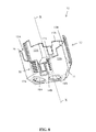
- Figure 8 shows another bottom part for the mounting box according to the invention.
- This bottom part 10 differs from the bottom part 10 shown in figure 1 mainly in that the guide means 17A, 17B do not extend radially outward from the perimeter of the bottom part 10.
- the bottom part 10 can thus be pushed into the top part 20 from the opening O1 at the first end 21A of the body portion 21 of the top part 20 in a second direction S2 opposite to the first direction S1.
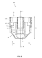
- FIG 9 shows another top part for the mounting box according to the invention.
- This top part 20 differs from the top part 20 shown in figure 2 mainly in that the second support members 24A, 24B do not contain any additional fastening means for the electrical component to be installed into the mounting box 100.
- the bottom part 10 can thus be pushed into the top part 20 from the opening O1 at the first end 21A of the body portion 21 of the top part 20 in a second direction S2 opposite to the first direction S1.
- Figure 10 shows a cross section of the mounting box comprising the bottom part of figure 8 and the top part of figure 9 in an extended state.
- the connection means 50, 60 correspond to the connection means 50, 60 in f igures 5 and 6 .
- Figure 11 shows a cross section of the mounting box comprising the bottom part of figure 8 and the top part of figure 9 in a contracted state.
- the connection means 50, 60 correspond to the connection means 50, 60 in figures 5 and 6 .
- Figure 12 shows three mounting boxes mounted to a wall.
- the bottom part 10 can be inserted into the top part 20 from the opening O1 at the first end 21 A of the body portion 21 of the top part 20.
- the outer perimeter of the bottom part 10 is so formed that it can be pushed through the first part from the opening O1 at the first end 21 A of the body portion 21 of the top part 20.
- FIG. 13 shows still another top part of the mounting box according to the invention.
- Each of the second support members 34A, 34B in this top part 30 comprises an extended portion 39A, 39B.
- the extended portions 30A, 39B extend the body portion 31 radially outwardly beyond the second support members 34A, 34B.
- Each of the extension portions 39A, 39B of the top part 30 form an extension mounting space extending the mounting space M1 that will be formed by the mounting box 100.
- the opening in the wall has to be adapted accordingly so that the top part 30 fits into the opening.
- This extended space within the top part 30 is needed so that a 2-gang socket outlet can be fitted into the top part 30 without raising the collar of the cover plate of the 2-gang socket outlet from the surface of the wall.
- a bottom part 10 according to figure 1 or 8 can be used also in connection with this top part 30.
- the lower portion of the top part 30 can correspond to the lower part of the top parts of figure 2 and 9 .
- the connection means 50, 60 shown in figures 5 and 6 can also be used in connection with this top part 30.
- the bottom part 10 in figure 1 can be inserted at least partly into the top part 20 in figure 2 in a first direction S1.
- the first direction S1 is directed axially X-X from the bottom of the mounting box 100 towards the opening O1 leading into the mounting space M1 in the mounting box 100.
- the bottom part 10 in figure 8 can be inserted at least partly into the top part 20 in figure 9 in a second opposite direction S2.
- the second direction S2 is directed axially X-X from the opening O1 leading into the mounting space M1 in the mounting box 100 towards the bottom of the mounting box 100.
- the top part 30 shown in figure 13 can be adapted to be used in connection with the bottom part 10 in figure 1 and in connection with the bottom part 10 in figure 8 .
- the bottom part 10 is advantageously formed as a single integral unit.
- the top part 20, 30 is also advantageously formed as a separate single integral unit.
- the bottom part 10 and the top part 20, 30 are advantageously made of plastic.
- the bottom part 10 and the top part 20, 30 can have a different colour, which makes it easier to distinguish the parts.
- the outer perimeter of the body portion 21, 31 of the top part 20, 30 could also be elliptic or polygonal which means that the bottom part 10 must be elliptic or polygonal in a corresponding way. Also the opening into which the mounting box 100 is to be installed must have a cross section corresponding to the cross section of the mounting box 100.
- the longitudinal center axis X-X passes through a middle point at the first end 21A, 31A of the body portion 21, 31 of the top part 20, 30.
- the longitudinal center axis X-X is perpendicular to the flange plane defined by the flange members 22.
- Connection means 50, 60 e.g. based on adjusting screws that adjust the axial position of the bottom part 10 within the top part 20, 30 could naturally be used instead of the connection means 50, 60 disclosed in the figures.
- the bottom part 10 can naturally be provided with pre-prepared points 18A, 18B in any position in the bottom portion 11 of the bottom part 10. There could be any number of pre-prepared points 18A, 18B in the bottom portion 11 positioned in any pattern in the bottom portion 11.
- the mounting box is an electrical mounting box that can be used as a distribution box for electrical wires and as a mounting box for an electrical component such as an electric switch, a socket, a TV socket etc.
Landscapes
- Engineering & Computer Science (AREA)
- Architecture (AREA)
- Civil Engineering (AREA)
- Structural Engineering (AREA)
- Connection Or Junction Boxes (AREA)
Abstract

Description
- The present invention relates to a mounting box according to the preamble of
claim 1. - There are two basic types of mounting boxes.
- The first type of mounting box is intended to be mounted in a wall comprising an inner wall and an outer wall at a distance from the inner wall. The mounting box is attached to the outer wall in a situation when the inner wall has not yet been erected. The tubes for the electric wires running in the space between the walls are connected to the mounting box before the inner wall is erected. The inner wall is then erected, whereby an opening is formed in the inner wall for an adjustment collar of the mounting box. The adjustment collar will protrude through the opening in the inner wall so that the planar outer surface of the adjustment collar is flush with the inner surface of the inner wall. Access to the mounting space provided within the mounting box is thus provided through the adjustment collar.
-
EP 2 822 120 - The second type of mounting box is also intended to be mounted in a wall comprising an inner wall and an outer wall at a distance from the first wall. This second type of mounting box is, however, mounted to the wall at the stage when also the inner wall has been erected. An opening is formed to the inner wall and the second type of mounting box is mounted into the wall by pushing the mounting box through the opening in the inner wall so that the flange means of the mounting box seat against the inner wall. The mounting box will thus be positioned completely inside the inner wall in the space between the inner wall and the outer wall except for the flange portion of the mounting box, which is seated against the first wall. Cables or flexible tubes with electrical wires are connected to the mounting box before the mounting box is pushed into the opening in the wall.
- A mounting box, or an installation box, of the second type comprises a casing having a tubular body with a first end and an opposite second end. The second end is closed with a bottom and the first end is open providing access to the interior of the mounting box. There are radially outwardly extending flange means at the first end of the casing. A mounting space is formed in the interior of the mounting box. The mounting box is pushed through an opening in the first wall so that the flange means seat against the first wall. The mounting box is then fastened to the first wall by fastening means.
- The invention is directed to the second type of mounting boxes.
- An object of the present invention is to achieve a mounting box that can be adapted according to the installation conditions.
- The mounting box according to the invention is characterized by what is stated in the
independent claim 1. - The mounting box comprises:
- a longitudinal centre axis,
- a bottom part comprising a bottom portion and a connection portion, said bottom part forming a bottom of the mounting box and being provided with pre-prepared points for tube and/or cable lead-ins,
- a separate top part being connectable to the bottom part, the top part being formed of a tubular body portion with a first end provided with radially outwardly from the body portion extending flange means, and fastening means cooperating with the flange means in order to fasten the mounting box to a wall, whereby
- the bottom part is adapted to be pushed in the axial direction at least partly into the top part so that an opening is formed through the body portion into a mounting space formed in the interior of the mounting box,
- the bottom part and the top part are connected to each other through first connection means positioned in connection with the bottom part and second connection means positioned in connection with the top part so that an axial position of the bottom part in relation to the top part can be varied in order to vary an axial length of the mounting box between a maximum axial length and a minimum axial length.
- The adjustable axial length of the installation box means that the same mounting box can be used in various installation environments. The space between the outer wall and the inner wall may vary in different installation environments. The axial length of the mounting box can be adjusted when the mounting box is installed so that the mounting box is suitable for the particular situation.
- The pre-prepared points providing tube and/or cable lead-ins in the bottom portion of the bottom part of the mounting box will move further away from the first end of the body portion of the top part when the mounting box is in the extended state i.e. has the maximum axial length. This means that there will be more space within the mounting box making it easier to do the mounting work within the mounting box.
- In the following the invention will be described in greater detail by means of preferred embodiments with reference to the attached drawings, in which:
-
Figure 1 shows a bottom part for the mounting box according to the invention, -
Figure 2 shows a top part for the mounting box according to the invention, -
Figure 3 shows the mounting box in an extended state, -
Figure 4 shows the mounting in a contracted state, -
Figure 5 shows a cross section of the mounting box offigure 3 , -
Figure 6 shows a cross section of the mounting box according tofigure 4 , -
Figure 7 shows two mounting boxes mounted to a wall, -
Figure 8 shows another bottom part for the mounting box according to the invention, -
Figure 9 shows another top part for the mounting box according to the invention, -
Figure 10 shows a cross section of the mounting box offigure 8 , -
Figure 11 shows a cross section of the mounting box offigure 9 , -
Figure 12 shows three mounting boxes mounted to a wall, -
Figure 13 shows still another top part for a mounting box according to the invention. -
Figure 1 shows a bottom part for the mounting box according to the invention. Thebottom part 10 has a longitudinal centre axis X-X and is composed of abottom portion 11 and aconnection portion 12. - The
bottom portion 11 of thebottom part 10 forms a closed space within it. Thebottom portion 11 comprises at least one pre-preparedpoint bottom portion 11 through thesepre-prepared points pre-prepared points mounting box 100 from an exterior of themounting box 100. The pre-preparedpoints mounting box 100 by punching out the shield covers from the pre-preparedpoints pre-prepared points pre-prepared points pre-prepared points pre-prepared point pre-prepared points bottom portion 11. - The
connection portion 12 of thebottom part 10 extends axially X-X outwards from thebottom portion 11 of thebottom part 10. Theconnection portion 12 comprises two diametrically oppositefirst slots connection portion 12 towards thebottom portion 11. Both axial X-X edges of thefirst slots X-X grooves 16. Theconnection portion 12 comprises two diametrically opposite axially X-X outwardly from a perimeter of thebottom portion 11 extendingfirst connection members first connection members first slots first connection members first slots first connection members bottom portion 11 of thebottom part 10. - The
connection portion 12 of thebottom part 10 comprises further two diametrically opposite axially X-X outwardly from the perimeter of thebottom portion 11 extendingsecond connection members second connection members first connection members second connection members second connection members U-shaped guide members guide members second connection members - The
second connection members figures 5 and6 . - The
connection portion 12 of thebottom part 10 has a generally tubular form and can be enclosed by a circle. The perimeter of theconnection portion 12 of thebottom part 10 is curved at thefirst support members second connection members first slots -
Figure 2 shows a top part for the mounting box according to the invention. Thetop part 20 has a longitudinal centre axis X-X and is composed of abody portion 21. Thetubular body portion 21 has afirst end 21A being provided with radially outwardly from thefirst end 21A of thebody portion 21 extending flange means 22. The flange means 22 comprises four radially outwardly extendingflange members 22 distributed at an equal angular distance from each other along the perimeter of thebody portion 21 of thetop part 20. Theflange members 22 define a flange plane. Thefirst end 21A of thebody portion 21 of thetop part 20 forms a planar surface. - The
body portion 21 of thetop part 20 comprises two diametrically opposite axially X-X outwardly from thebody portion 21 extendingscrew towers screw tower axial guide protrusion 26. The guide protrusions 26 are received by the corresponding axialX-X grooves 16 in thefirst slots bottom part 10. Thetop part 20 comprises two diametrically opposite axially X-X outwardly from thebottom portion 21 extendingfirst support members first support members first support members rectangular screw tower first support members flange members 22 and comprises anopening 210 for a fastening screw extending to the lower portion of thescrew tower mounting box 100. Each of the screw towers 25A, 25B has an axial X-X length L3, which is greater than the axial X-X length L4 of thefirst support members - The
body portion 21 of thetop part 20 comprises further two diametrically opposite axially X-X extendingsecond support members second support members first support members second support members recesses 240 on the inner perimeter of thesecond support members mounting box 100. Each of thesecond support members second slots second support member second slots top part 20 receive theguide members bottom part 10. - The
second support members figures 5 and6 . - The
top part 20 can be enclosed by a circle. The perimeter of thetop part 20 has curved portions at thefirst support members second support members boxes 100 together from any of these straight portions. -
Figure 3 shows the mounting box in an extended state. Thebottom part 10 has been pushed at least partly into thetop part 20 in a first direction S1 from the bottom of thetop part 20. The screw towers 25A, 25B of thetop part 20 glide into thefirst slots bottom part 10 so that theguide protrusions 26 at the edges of the screw towers 25A, 25B glide in thegrooves 16 at the edges of thefirst slots guide members bottom part 10 glide into correspondingsecond slots top part 20. - The
second connection members bottom part 10 comprises first connection means 50 being positioned at both sides of theguide elements second part 20 comprises second opposite connection means 60 being positioned on thesecond support members top part 20, whereby the first connections means 50 cooperate with the second connection means 60. Thebottom part 10 and thetop part 20 are connected to each other through the first connection means 50 and the second connection means 60 so that an axial X-X length of the mountingbox 100 can be varied between a maximum axial length L1 and a minimum axial length L2 by varying the axial X-X position of thesecond part 20 in relation to thefirst part 10. - There are small
radial protrusions 21C extending axially X-X along the outer perimeter of thebody portion 21 of thetop part 20. Theradial protrusions 21C grip into the edges of the opening into which themounting box 100 is pushed eliminating rotation of the mountingbox 100 in the opening. - There is an opening O1 passing from the
first end 21A of thebody portion 21 of thetop part 20 into the interior of the mountingbox 100. The interior of the mountingbox 100 forms a mounting space M1. The mounting space M1 in the interior of the mountingbox 100 is intended for accommodating an electrical component such as a wall socket or a light switch. - The figure shows also fastening means 220, 230 cooperating with the flange means 22 in order to fasten the
mounting box 100 to a wall. The fastening means 220, 230 comprises afastening screw 220 and afastening member 230. Thefastening screw 220 passes through theopening 210 in the first end of thescrew tower fastening member 230 located in the lower portion of thescrew tower box 100 has been pushed into the hole in the wall thefastening screw 220 is turned clockwise with a screw driver, whereby thefastening member 230 is turned radially outwardly until the side surface of thefastening member 230 seats against the inner side surface of thescrew tower fastening member 230 will then start moving in the first direction S1 towards the first end of thecrew tower fastening screw 220 is turned further clockwise. Thefastening member 230 will then finally seat against the inner surface of the wall and theflange members 22 will seat against the outer surface of the wall when the mounting box is secured to the wall. The figure shows also thescrews 250 for the fastening of the electrical component to be accommodated in themounting box 100. - The
pre-prepared points bottom portion 11 of thebottom part 10 are in this extended state furthermost from thefirst end 21A of thebody portion 21 of thetop part 20. This means that the mounting space M1 within the mountingbox 100 reaches its maximum value in this state. -
Figure 4 shows the mounting box in a contracted state. Thebottom part 10 has been pushed further into thetop part 20 in the first direction S1. The axial X-X length L2 of the mountingbox 100 is at its minimum value in this figure. The upper end of theguide member second slots bottom part 20 into thetop part 10 in the first direction S1. - The
pre-prepared points bottom portion 11 of thebottom part 10 are in this contracted state nearest to thefirst end 21A of thebody portion 21 of thetop part 20. This means that the mounting space M1 within the mountingbox 100 reaches its minimum value in this state. -
Figure 5 shows a cross section of the mounting box offigure 3 . The axial length L1 of the mounting box is at the maximum value L1 in this figure. - The first connection means 50 on the
bottom part 10 comprises axially X-X displaced and radially directedgrooves 52. The radially directedgrooves 52 are positioned adjacent to each other at an axial X-X distance from each other on thesecond connection members guide members figure 1 ). There is further a first radially outwards directedfirst notch 51 at an upper axial X-X end of thesecond connection members first notch 51 on both sides of theguide members figure 1 ). - The second connection means 60 on the
top part 20 comprises a radially inwards directedsecond notch 61 at a lower axial X-X end of thesecond support members second notch 61 at both outer sides on thesecond support member second notches 61 corresponds to the position of thefirst notches 51. - A snap locking is thus achieved between the
bottom part 10 and thetop part 20 when thesecond notch 61 at the lower axial X-X end of thesecond support members respective groove 52 on the first connection means 50 so that the axial X-X length of the mountingbox 100 can be varied between a maximum axial X-X length L1 and a minimum axial X-X length L2 by varying the axial X-X position of thebottom part 10 in relation to thetop part 20. - The
first notch 51 rests against the second notch 42. It requires much more force to slip thefirst notch 51 over thesecond notch 61 in order to disengage thebottom part 10 totally from thetop part 20 compared to the force required to move thesecond notch 61 between thedifferent grooves 52 in the first connection means 50. The axial X-X adjustment of thebottom part 10 in relation to thetop part 20 can thus be done stepwise betweenconsecutive grooves 52. The axial X-X adjustment of thebottom part 10 can be done simply by hand force without any additional equipment due to the snap locking. -
Figure 6 shows a cross section of the mounting box offigure 4 . The axial length L2 of the mountingbox 100 is at the minimum value L2 in this figure. The upper edges of theguide members second connection members second slots second support members -
Figure 7 shows two mounting boxes mounted to a wall. The wall comprises afirst wall 300 and a secondparallel wall 310 at a distance from thefirst wall 300. Thefirst wall 300 can be aninner wall 300 of a space e.g. a room, whereby thesecond wall 310 forms theouter wall 310 of the wall construction. The mountingbox 100 is adapted to be installed into anopening 305 in thefirst wall 300 by pushing the mountingbox 100 into theopening 305 of thefirst wall sheet 300 from afirst side 301 of thefirst wall 300. Thefirst side 301 of thefirst wall 300 is facing towards the interior of the space delimited by the wall structure. The mountingbox 100 to the left in the figure is in a state where the axial X-X length L1 of the mountingbox 100 is at a maximum. The mountingbox 100 to the right in the figure is in a state where the axial X-X length L2 of the mountingbox 100 is at a minimum. The thickness of the wall construction can vary so that the distance between thefirst wall 300 and thesecond wall 310 varies or so that the thickness of thefirst wall 300 varies. There is thus a need to be able to adapt the axial X-X length L1, L2 of the mountingbox 100 according to this. The distance L3 from thefirst side 301 of thefirst wall 300 to thepre-prepared points mounting box 100 situated to the left in the figure. The distance L4 from thefirst side 301 of thefirst wall 300 to thepre-prepared points mounting box 100 situated to the right in the figure. The mounting space within the mountingbox 100 to the left in the figure is thus greater compared to the mounting space within the mountingbox 100 to the right in the figure. This mounting space within the mountingbox 100 can be adjusted at any time after themounting box 100 has been attached to thewall 300 so that the flange means 22 seat against the first side 101 of thefirst wall 300. -
Figure 8 shows another bottom part for the mounting box according to the invention. Thisbottom part 10 differs from thebottom part 10 shown infigure 1 mainly in that the guide means 17A, 17B do not extend radially outward from the perimeter of thebottom part 10. Thebottom part 10 can thus be pushed into thetop part 20 from the opening O1 at thefirst end 21A of thebody portion 21 of thetop part 20 in a second direction S2 opposite to the first direction S1. -
Figure 9 shows another top part for the mounting box according to the invention. Thistop part 20 differs from thetop part 20 shown infigure 2 mainly in that thesecond support members box 100. Thebottom part 10 can thus be pushed into thetop part 20 from the opening O1 at thefirst end 21A of thebody portion 21 of thetop part 20 in a second direction S2 opposite to the first direction S1. -
Figure 10 shows a cross section of the mounting box comprising the bottom part offigure 8 and the top part offigure 9 in an extended state. The connection means 50, 60 correspond to the connection means 50, 60 in figures 5 and6 . -
Figure 11 shows a cross section of the mounting box comprising the bottom part offigure 8 and the top part offigure 9 in a contracted state. The connection means 50, 60 correspond to the connection means 50, 60 infigures 5 and6 . -
Figure 12 shows three mounting boxes mounted to a wall. Thebottom part 10 can be inserted into thetop part 20 from the opening O1 at thefirst end 21 A of thebody portion 21 of thetop part 20. The outer perimeter of thebottom part 10 is so formed that it can be pushed through the first part from the opening O1 at thefirst end 21 A of thebody portion 21 of thetop part 20. -
Figure 13 shows still another top part of the mounting box according to the invention. Each of thesecond support members 34A, 34B in thistop part 30 comprises anextended portion 39A, 39B. The extended portions 30A, 39B extend the body portion 31 radially outwardly beyond thesecond support members 34A, 34B. Each of theextension portions 39A, 39B of thetop part 30 form an extension mounting space extending the mounting space M1 that will be formed by the mountingbox 100. The opening in the wall has to be adapted accordingly so that thetop part 30 fits into the opening. This extended space within thetop part 30 is needed so that a 2-gang socket outlet can be fitted into thetop part 30 without raising the collar of the cover plate of the 2-gang socket outlet from the surface of the wall. Abottom part 10 according tofigure 1 or8 can be used also in connection with thistop part 30. The lower portion of thetop part 30 can correspond to the lower part of the top parts offigure 2 and9 . The connection means 50, 60 shown infigures 5 and6 can also be used in connection with thistop part 30. - The
bottom part 10 infigure 1 can be inserted at least partly into thetop part 20 infigure 2 in a first direction S1. The first direction S1 is directed axially X-X from the bottom of the mountingbox 100 towards the opening O1 leading into the mounting space M1 in themounting box 100. - The
bottom part 10 infigure 8 can be inserted at least partly into thetop part 20 infigure 9 in a second opposite direction S2. The second direction S2 is directed axially X-X from the opening O1 leading into the mounting space M1 in themounting box 100 towards the bottom of the mountingbox 100. - The
top part 30 shown infigure 13 can be adapted to be used in connection with thebottom part 10 infigure 1 and in connection with thebottom part 10 infigure 8 . - The
bottom part 10 is advantageously formed as a single integral unit. Thetop part bottom part 10 and thetop part bottom part 10 and thetop part - The outer perimeter of the
body portion 21, 31 of thetop part bottom part 10 must be elliptic or polygonal in a corresponding way. Also the opening into which themounting box 100 is to be installed must have a cross section corresponding to the cross section of the mountingbox 100. The longitudinal center axis X-X passes through a middle point at thefirst end 21A, 31A of thebody portion 21, 31 of thetop part flange members 22. - Connection means 50, 60 e.g. based on adjusting screws that adjust the axial position of the
bottom part 10 within thetop part - The
bottom part 10 can naturally be provided withpre-prepared points bottom portion 11 of thebottom part 10. There could be any number ofpre-prepared points bottom portion 11 positioned in any pattern in thebottom portion 11. - The mounting box is an electrical mounting box that can be used as a distribution box for electrical wires and as a mounting box for an electrical component such as an electric switch, a socket, a TV socket etc.
- The invention and its embodiments are not limited to the examples described above but may vary within the scope of the claims.
Claims (15)
- A mounting box (100), characterized in that it comprises:a longitudinal centre axis (X-X),a bottom part (10) comprising a bottom portion (11) and a connection portion (12), said bottom part (10) forming a bottom of the mounting box (100) and being provided with at least one pre-prepared point (18A, 18B) for a tube and/or cable lead-in,a separate top part (20, 30) being connectable to the bottom part (10), the top part (20, 30) being formed of a tubular body portion (21, 31) with a first end (21A, 31A) provided with radially outwardly from the body portion (21, 31) extending flange means (22, 32), and fastening means (220, 230) cooperating with the flange means (22, 32) in order to fasten the mounting box (100) to a wall (300), wherebythe bottom part (10) is adapted to be pushed in the axial (X-X) direction at least partly into the top part (20, 30) so that an opening (O1) is formed through the body portion (21, 31) into a mounting space (M1) formed in the interior of the mounting box (100),the bottom part (10) and the top part (20, 30) are connected to each other through first connection means (50) positioned in connection with the bottom part (10) and second connection means (60) positioned in connection with the top part (20, 30) so that an axial (X-X) position of the bottom part (10) in relation to the top part (20, 30) can be varied in order to vary an axial (X-X) length of the mounting box (100) between a maximum axial length (L1) and a minimum axial length (L2).
- A mounting box (100) according to claim 1, characterized in that the first connection means (50) and the second connection means (60) provide a snap connection between the bottom part (10) and the top part (20).
- A mounting box (100) according to claim 1 or 2, characterized in that the first connection means (50) are formed as an integral part of the bottom part (10).
- A mounting box (100) according to any one of claims 1 to 3, characterized in that the second connection means (60) are formed as an integral part of the top part (20).
- A mounting box (100) according to any one of claims 1-4, characterized in that:the first connection means (50) comprises radially directed grooves (52) being positioned axially X-X consecutively on an outer surface of the bottom part (10) and a radially outwardly directed first notch (51) on an outer end of the bottom part (10),the second connection means (60) comprises a second radially inwardly directed notch (61) on an outer end of the top part (20), whereby a snap locking is achieved between the bottom part (10) and the top part (20) when the second notch (61) of the second connection means (60) seats into a respective groove (52) on the first connection means (50) so that the axial (X-X) position of the bottom part (10) can be varied in relation to the top part (20) in order to vary the axial (X-X) length of the mounting box (100) between the maximum axial length (L1) and the minimum axial length (L2).
- A mounting box (100) according to any one of claims 1 to 5, characterized in that the top part (20, 30) comprises two diametrically opposite, axially (X-X) outwardly from the body portion (21, 31) of the top part (20, 30) extending screw towers (25A, 25B), both axial (X-X) edges of each screw tower (25A, 25B) comprising an axial (X-X) guide protrusion (26).
- A mounting box (100) according to claim 6, characterized in that the connection portion (12) of the bottom part (10) comprises two diametrically opposite first slots (15A, 15B) extending axially (X-X) from the outer edge of the connection portion (12) towards the bottom portion (11), both axial (X-X) edges of each of the first slots (15A, 15B) being provided with an axial (X-X) groove (16) for receiving the axial guide protrusions (26) of the screw towers (25A, 25B) of the top part (20, 30).
- A mounting box (100) according to claim 7, characterized in that the connection portion (12) of the bottom part (10) comprises:two diametrically opposite axially (X-X) outwardly from a perimeter the bottom portion (11) extending first connection members (13A, 13B) being provided with the first slot (15A, 15B) extending axially (X-X) from the outer edge of the first connection members (13A, 13B) towards the bottom portion (11),two diametrically opposite axially (X-X) outwardly from the perimeter of the bottom portion (11) extending second connection members (14A, 14B), the axial (X-X) edges of each of the second connection members (14A, 14B) joining the axial (X-X) edges of two adjacent first connection members (13A, 13B), the second connection members (14A, 14B) comprising axially (X-X) extending guide members (17A, 17B) protruding outwards from a perimeter of the second connection members (14A, 14B).
- A mounting box (100) according to claim 8, characterized in that the body portion (21) of the top part (20) comprises:two diametrically opposite axially (X-X) extending first support members (23A, 23B) being provided with the axially (X-X) extending screw towers (25A, 25B) positioned in the centre of the perimeter of each of the first support members (23A, 23B),two diametrically opposite axially (X-X) extending second support members (24A, 24B), the axial (X-X) edges of each of the second support members (24A, 24B) joining the axial (X-X) edges of two adjacent first support members (23A, 23B), each of the second support members (24A, 24B) comprising second slots (27A, 27B) for receiving the guide members (17A, 17B) of the bottom part (10).
- A mounting box (100) according to claim 9, characterized in that first end surfaces of the screw towers (25A, 25B) are flush with the plane formed by the flange means (22).
- A mounting box (100) according to claim 10, characterized in that the first end surfaces of the screw towers (25A, 25B) comprises recesses (240) extending axially (X-X) into said screw towers (25A, 25B), whereby an installation plate of the electrical component such as a wall socket or a light switch to be accommodated in the mounting box (100) can be seated on the first end surfaces of the screw towers (25A, 25B) and attached with screws (250) to said first end surfaces.
- A mounting box (100) according to any one of claims 8 to 11, characterized in that the first connection means (50) form an integral part of the second connection members (14A, 14B) of the bottom part (10).
- A mounting box (100) according to any one of claims 9 to 12, characterized in that the second connection means (60) form an integral part of the second support members (24A, 24B) of the top part (20).
- A mounting box (100) according to any one of claims 9 to 13, characterized in that each of the second support members (34A, 34B) in the top part (30) comprises an extended portion (39A, 39B) extending the body portion (31) radially outwardly beyond the second support members (34A, 34B), whereby a 2-gang socket outlet can be fitted into the mounting box (100).
- A mounting box (100) according to any one of claims 1 to 14, characterized in that the distance from the flange means (22, 32) to the at least one pre-prepared point (18A, 18B) for a tube and/or cable lead-in changes the same amount as the axial length of the mounting box (100) changes when the an axial (X-X) position of the bottom part (10) in relation to the top part (20, 30) is changed between the maximum axial length (L1) and the minimum axial length (L2).
Priority Applications (3)
| Application Number | Priority Date | Filing Date | Title |
|---|---|---|---|
| DK15155885.5T DK3059817T3 (en) | 2015-02-20 | 2015-02-20 | MOUNTING BOX |
| EP15155885.5A EP3059817B1 (en) | 2015-02-20 | 2015-02-20 | Mounting box |
| LTEP15155885.5T LT3059817T (en) | 2015-02-20 | 2015-02-20 | Mounting box |
Applications Claiming Priority (1)
| Application Number | Priority Date | Filing Date | Title |
|---|---|---|---|
| EP15155885.5A EP3059817B1 (en) | 2015-02-20 | 2015-02-20 | Mounting box |
Publications (2)
| Publication Number | Publication Date |
|---|---|
| EP3059817A1 true EP3059817A1 (en) | 2016-08-24 |
| EP3059817B1 EP3059817B1 (en) | 2020-09-30 |
Family
ID=52477723
Family Applications (1)
| Application Number | Title | Priority Date | Filing Date |
|---|---|---|---|
| EP15155885.5A Active EP3059817B1 (en) | 2015-02-20 | 2015-02-20 | Mounting box |
Country Status (3)
| Country | Link |
|---|---|
| EP (1) | EP3059817B1 (en) |
| DK (1) | DK3059817T3 (en) |
| LT (1) | LT3059817T (en) |
Cited By (4)
| Publication number | Priority date | Publication date | Assignee | Title |
|---|---|---|---|---|
| WO2018060338A1 (en) * | 2016-09-29 | 2018-04-05 | FILUXX-Systems GmbH | Flush-mount box for lamp connections |
| EP3496219A1 (en) * | 2017-12-07 | 2019-06-12 | ABB Schweiz AG | Connection casing |
| CN109887412A (en) * | 2019-04-25 | 2019-06-14 | 杭州邦辉自动化工程技术有限公司 | A mosaic functional component |
| US11557888B2 (en) | 2019-02-14 | 2023-01-17 | Erico International Corporation | Adjustable depth electrical wall mount ring |
Citations (5)
| Publication number | Priority date | Publication date | Assignee | Title |
|---|---|---|---|---|
| US4098423A (en) * | 1977-03-10 | 1978-07-04 | Louis Marrero | Self-aligning outlet box assembly |
| JP2002223515A (en) * | 2001-01-24 | 2002-08-09 | Shida Densetsu Kk | Wiring box |
| EP1511144A1 (en) * | 2003-09-01 | 2005-03-02 | Legrand | Flush mounted box with mounting ring |
| WO2012042232A2 (en) * | 2010-10-01 | 2012-04-05 | Thorn Security Limited | Mounting unit |
| EP2822120A1 (en) | 2013-07-05 | 2015-01-07 | ABB Oy | Mounting box |
Family Cites Families (1)
| Publication number | Priority date | Publication date | Assignee | Title |
|---|---|---|---|---|
| DE102010026553A1 (en) * | 2010-07-07 | 2012-01-12 | Maximilian Rüttiger | Spacer outlet for drying cleaned thin walled bottom of e.g. furniture, has extensible tube formed from incorporation unit, where extensible tube is positioned in three preferential operational positions |
-
2015
- 2015-02-20 LT LTEP15155885.5T patent/LT3059817T/en unknown
- 2015-02-20 EP EP15155885.5A patent/EP3059817B1/en active Active
- 2015-02-20 DK DK15155885.5T patent/DK3059817T3/en active
Patent Citations (5)
| Publication number | Priority date | Publication date | Assignee | Title |
|---|---|---|---|---|
| US4098423A (en) * | 1977-03-10 | 1978-07-04 | Louis Marrero | Self-aligning outlet box assembly |
| JP2002223515A (en) * | 2001-01-24 | 2002-08-09 | Shida Densetsu Kk | Wiring box |
| EP1511144A1 (en) * | 2003-09-01 | 2005-03-02 | Legrand | Flush mounted box with mounting ring |
| WO2012042232A2 (en) * | 2010-10-01 | 2012-04-05 | Thorn Security Limited | Mounting unit |
| EP2822120A1 (en) | 2013-07-05 | 2015-01-07 | ABB Oy | Mounting box |
Cited By (4)
| Publication number | Priority date | Publication date | Assignee | Title |
|---|---|---|---|---|
| WO2018060338A1 (en) * | 2016-09-29 | 2018-04-05 | FILUXX-Systems GmbH | Flush-mount box for lamp connections |
| EP3496219A1 (en) * | 2017-12-07 | 2019-06-12 | ABB Schweiz AG | Connection casing |
| US11557888B2 (en) | 2019-02-14 | 2023-01-17 | Erico International Corporation | Adjustable depth electrical wall mount ring |
| CN109887412A (en) * | 2019-04-25 | 2019-06-14 | 杭州邦辉自动化工程技术有限公司 | A mosaic functional component |
Also Published As
| Publication number | Publication date |
|---|---|
| EP3059817B1 (en) | 2020-09-30 |
| DK3059817T3 (en) | 2021-01-04 |
| LT3059817T (en) | 2021-01-11 |
Similar Documents
| Publication | Publication Date | Title |
|---|---|---|
| EP3059817A1 (en) | Mounting box | |
| US7615714B2 (en) | Button style cord connector | |
| US9667053B2 (en) | Adjustable floor box | |
| US7645947B2 (en) | Electrical connector with outer retainer ring and internal unidirectional conductor retainer | |
| US6664467B1 (en) | Raceway non-metallic overlapping faceplate mounting bracket | |
| US5285009A (en) | Electrical floor box | |
| CA2216440C (en) | Non-metallic floor box | |
| WO2013016431A2 (en) | Spring lock electrical fitting | |
| US7227085B1 (en) | Reconfigurable conduit body assembly | |
| US11248721B2 (en) | Support device for use with electrical box | |
| US10644491B2 (en) | Electrical box cable connector | |
| US11641096B2 (en) | Electrical box cable management and support bracket assembly, system and method | |
| US10069289B2 (en) | In-floor electrical fitting having cover with recessed outer flange | |
| KR101916754B1 (en) | boxes for telecommunications | |
| US20230378732A1 (en) | Protective outlet cover | |
| EP3496219A1 (en) | Connection casing | |
| EP3591815B1 (en) | Rotating electric machine | |
| US20200032955A1 (en) | Apparatuses Including Fixtures and/or Fixture Mounts and Related Methods | |
| EP3059818B1 (en) | Mounting box | |
| US10742012B2 (en) | Screw less cover plate for electrical fixtures | |
| WO1981000793A1 (en) | Wall for partitioning into sections a channel for electrical cables | |
| HU219248B (en) | Assembly molder half-covered box via cable-tunnel and method for mounting it | |
| US2129442A (en) | Junction box mechanism | |
| EP0465077A1 (en) | An outlet box for a cable duct arrangement | |
| US20250226609A1 (en) | Cable connector systems and methods |
Legal Events
| Date | Code | Title | Description |
|---|---|---|---|
| PUAI | Public reference made under article 153(3) epc to a published international application that has entered the european phase |
Free format text: ORIGINAL CODE: 0009012 |
|
| AK | Designated contracting states |
Kind code of ref document: A1 Designated state(s): AL AT BE BG CH CY CZ DE DK EE ES FI FR GB GR HR HU IE IS IT LI LT LU LV MC MK MT NL NO PL PT RO RS SE SI SK SM TR |
|
| AX | Request for extension of the european patent |
Extension state: BA ME |
|
| STAA | Information on the status of an ep patent application or granted ep patent |
Free format text: STATUS: REQUEST FOR EXAMINATION WAS MADE |
|
| 17P | Request for examination filed |
Effective date: 20161107 |
|
| RBV | Designated contracting states (corrected) |
Designated state(s): AL AT BE BG CH CY CZ DE DK EE ES FI FR GB GR HR HU IE IS IT LI LT LU LV MC MK MT NL NO PL PT RO RS SE SI SK SM TR |
|
| STAA | Information on the status of an ep patent application or granted ep patent |
Free format text: STATUS: EXAMINATION IS IN PROGRESS |
|
| 17Q | First examination report despatched |
Effective date: 20170601 |
|
| RAP1 | Party data changed (applicant data changed or rights of an application transferred) |
Owner name: ABB SCHWEIZ AG |
|
| GRAP | Despatch of communication of intention to grant a patent |
Free format text: ORIGINAL CODE: EPIDOSNIGR1 |
|
| STAA | Information on the status of an ep patent application or granted ep patent |
Free format text: STATUS: GRANT OF PATENT IS INTENDED |
|
| INTG | Intention to grant announced |
Effective date: 20200401 |
|
| GRAS | Grant fee paid |
Free format text: ORIGINAL CODE: EPIDOSNIGR3 |
|
| RAP1 | Party data changed (applicant data changed or rights of an application transferred) |
Owner name: ABB SCHWEIZ AG |
|
| GRAA | (expected) grant |
Free format text: ORIGINAL CODE: 0009210 |
|
| STAA | Information on the status of an ep patent application or granted ep patent |
Free format text: STATUS: THE PATENT HAS BEEN GRANTED |
|
| AK | Designated contracting states |
Kind code of ref document: B1 Designated state(s): AL AT BE BG CH CY CZ DE DK EE ES FI FR GB GR HR HU IE IS IT LI LT LU LV MC MK MT NL NO PL PT RO RS SE SI SK SM TR |
|
| REG | Reference to a national code |
Ref country code: GB Ref legal event code: FG4D Ref country code: CH Ref legal event code: EP |
|
| REG | Reference to a national code |
Ref country code: AT Ref legal event code: REF Ref document number: 1319769 Country of ref document: AT Kind code of ref document: T Effective date: 20201015 |
|
| REG | Reference to a national code |
Ref country code: DE Ref legal event code: R096 Ref document number: 602015059719 Country of ref document: DE |
|
| REG | Reference to a national code |
Ref country code: IE Ref legal event code: FG4D |
|
| REG | Reference to a national code |
Ref country code: FI Ref legal event code: FGE |
|
| REG | Reference to a national code |
Ref country code: DK Ref legal event code: T3 Effective date: 20201221 |
|
| REG | Reference to a national code |
Ref country code: SE Ref legal event code: TRGR |
|
| REG | Reference to a national code |
Ref country code: NO Ref legal event code: T2 Effective date: 20200930 |
|
| REG | Reference to a national code |
Ref country code: NL Ref legal event code: FP |
|
| PG25 | Lapsed in a contracting state [announced via postgrant information from national office to epo] |
Ref country code: HR Free format text: LAPSE BECAUSE OF FAILURE TO SUBMIT A TRANSLATION OF THE DESCRIPTION OR TO PAY THE FEE WITHIN THE PRESCRIBED TIME-LIMIT Effective date: 20200930 Ref country code: BG Free format text: LAPSE BECAUSE OF FAILURE TO SUBMIT A TRANSLATION OF THE DESCRIPTION OR TO PAY THE FEE WITHIN THE PRESCRIBED TIME-LIMIT Effective date: 20201230 Ref country code: GR Free format text: LAPSE BECAUSE OF FAILURE TO SUBMIT A TRANSLATION OF THE DESCRIPTION OR TO PAY THE FEE WITHIN THE PRESCRIBED TIME-LIMIT Effective date: 20201231 |
|
| REG | Reference to a national code |
Ref country code: AT Ref legal event code: MK05 Ref document number: 1319769 Country of ref document: AT Kind code of ref document: T Effective date: 20200930 Ref country code: EE Ref legal event code: FG4A Ref document number: E020232 Country of ref document: EE Effective date: 20201230 |
|
| PG25 | Lapsed in a contracting state [announced via postgrant information from national office to epo] |
Ref country code: RS Free format text: LAPSE BECAUSE OF FAILURE TO SUBMIT A TRANSLATION OF THE DESCRIPTION OR TO PAY THE FEE WITHIN THE PRESCRIBED TIME-LIMIT Effective date: 20200930 |
|
| PG25 | Lapsed in a contracting state [announced via postgrant information from national office to epo] |
Ref country code: SM Free format text: LAPSE BECAUSE OF FAILURE TO SUBMIT A TRANSLATION OF THE DESCRIPTION OR TO PAY THE FEE WITHIN THE PRESCRIBED TIME-LIMIT Effective date: 20200930 Ref country code: RO Free format text: LAPSE BECAUSE OF FAILURE TO SUBMIT A TRANSLATION OF THE DESCRIPTION OR TO PAY THE FEE WITHIN THE PRESCRIBED TIME-LIMIT Effective date: 20200930 Ref country code: PT Free format text: LAPSE BECAUSE OF FAILURE TO SUBMIT A TRANSLATION OF THE DESCRIPTION OR TO PAY THE FEE WITHIN THE PRESCRIBED TIME-LIMIT Effective date: 20210201 Ref country code: CZ Free format text: LAPSE BECAUSE OF FAILURE TO SUBMIT A TRANSLATION OF THE DESCRIPTION OR TO PAY THE FEE WITHIN THE PRESCRIBED TIME-LIMIT Effective date: 20200930 |
|
| PG25 | Lapsed in a contracting state [announced via postgrant information from national office to epo] |
Ref country code: AT Free format text: LAPSE BECAUSE OF FAILURE TO SUBMIT A TRANSLATION OF THE DESCRIPTION OR TO PAY THE FEE WITHIN THE PRESCRIBED TIME-LIMIT Effective date: 20200930 Ref country code: AL Free format text: LAPSE BECAUSE OF FAILURE TO SUBMIT A TRANSLATION OF THE DESCRIPTION OR TO PAY THE FEE WITHIN THE PRESCRIBED TIME-LIMIT Effective date: 20200930 Ref country code: ES Free format text: LAPSE BECAUSE OF FAILURE TO SUBMIT A TRANSLATION OF THE DESCRIPTION OR TO PAY THE FEE WITHIN THE PRESCRIBED TIME-LIMIT Effective date: 20200930 Ref country code: IS Free format text: LAPSE BECAUSE OF FAILURE TO SUBMIT A TRANSLATION OF THE DESCRIPTION OR TO PAY THE FEE WITHIN THE PRESCRIBED TIME-LIMIT Effective date: 20210130 Ref country code: PL Free format text: LAPSE BECAUSE OF FAILURE TO SUBMIT A TRANSLATION OF THE DESCRIPTION OR TO PAY THE FEE WITHIN THE PRESCRIBED TIME-LIMIT Effective date: 20200930 |
|
| PG25 | Lapsed in a contracting state [announced via postgrant information from national office to epo] |
Ref country code: SK Free format text: LAPSE BECAUSE OF FAILURE TO SUBMIT A TRANSLATION OF THE DESCRIPTION OR TO PAY THE FEE WITHIN THE PRESCRIBED TIME-LIMIT Effective date: 20200930 |
|
| REG | Reference to a national code |
Ref country code: DE Ref legal event code: R097 Ref document number: 602015059719 Country of ref document: DE |
|
| PLBE | No opposition filed within time limit |
Free format text: ORIGINAL CODE: 0009261 |
|
| STAA | Information on the status of an ep patent application or granted ep patent |
Free format text: STATUS: NO OPPOSITION FILED WITHIN TIME LIMIT |
|
| 26N | No opposition filed |
Effective date: 20210701 |
|
| PG25 | Lapsed in a contracting state [announced via postgrant information from national office to epo] |
Ref country code: MC Free format text: LAPSE BECAUSE OF FAILURE TO SUBMIT A TRANSLATION OF THE DESCRIPTION OR TO PAY THE FEE WITHIN THE PRESCRIBED TIME-LIMIT Effective date: 20200930 |
|
| GBPC | Gb: european patent ceased through non-payment of renewal fee |
Effective date: 20210220 |
|
| REG | Reference to a national code |
Ref country code: BE Ref legal event code: MM Effective date: 20210228 |
|
| PG25 | Lapsed in a contracting state [announced via postgrant information from national office to epo] |
Ref country code: LI Free format text: LAPSE BECAUSE OF NON-PAYMENT OF DUE FEES Effective date: 20210228 Ref country code: LU Free format text: LAPSE BECAUSE OF NON-PAYMENT OF DUE FEES Effective date: 20210220 Ref country code: CH Free format text: LAPSE BECAUSE OF NON-PAYMENT OF DUE FEES Effective date: 20210228 Ref country code: IT Free format text: LAPSE BECAUSE OF FAILURE TO SUBMIT A TRANSLATION OF THE DESCRIPTION OR TO PAY THE FEE WITHIN THE PRESCRIBED TIME-LIMIT Effective date: 20200930 |
|
| PG25 | Lapsed in a contracting state [announced via postgrant information from national office to epo] |
Ref country code: SI Free format text: LAPSE BECAUSE OF FAILURE TO SUBMIT A TRANSLATION OF THE DESCRIPTION OR TO PAY THE FEE WITHIN THE PRESCRIBED TIME-LIMIT Effective date: 20200930 |
|
| PG25 | Lapsed in a contracting state [announced via postgrant information from national office to epo] |
Ref country code: FR Free format text: LAPSE BECAUSE OF NON-PAYMENT OF DUE FEES Effective date: 20210228 Ref country code: IE Free format text: LAPSE BECAUSE OF NON-PAYMENT OF DUE FEES Effective date: 20210220 Ref country code: GB Free format text: LAPSE BECAUSE OF NON-PAYMENT OF DUE FEES Effective date: 20210220 |
|
| PG25 | Lapsed in a contracting state [announced via postgrant information from national office to epo] |
Ref country code: IS Free format text: LAPSE BECAUSE OF FAILURE TO SUBMIT A TRANSLATION OF THE DESCRIPTION OR TO PAY THE FEE WITHIN THE PRESCRIBED TIME-LIMIT Effective date: 20210130 |
|
| PG25 | Lapsed in a contracting state [announced via postgrant information from national office to epo] |
Ref country code: BE Free format text: LAPSE BECAUSE OF NON-PAYMENT OF DUE FEES Effective date: 20210228 |
|
| PG25 | Lapsed in a contracting state [announced via postgrant information from national office to epo] |
Ref country code: HU Free format text: LAPSE BECAUSE OF FAILURE TO SUBMIT A TRANSLATION OF THE DESCRIPTION OR TO PAY THE FEE WITHIN THE PRESCRIBED TIME-LIMIT; INVALID AB INITIO Effective date: 20150220 |
|
| PG25 | Lapsed in a contracting state [announced via postgrant information from national office to epo] |
Ref country code: CY Free format text: LAPSE BECAUSE OF FAILURE TO SUBMIT A TRANSLATION OF THE DESCRIPTION OR TO PAY THE FEE WITHIN THE PRESCRIBED TIME-LIMIT Effective date: 20200930 |
|
| PG25 | Lapsed in a contracting state [announced via postgrant information from national office to epo] |
Ref country code: MK Free format text: LAPSE BECAUSE OF FAILURE TO SUBMIT A TRANSLATION OF THE DESCRIPTION OR TO PAY THE FEE WITHIN THE PRESCRIBED TIME-LIMIT Effective date: 20200930 |
|
| PG25 | Lapsed in a contracting state [announced via postgrant information from national office to epo] |
Ref country code: MT Free format text: LAPSE BECAUSE OF FAILURE TO SUBMIT A TRANSLATION OF THE DESCRIPTION OR TO PAY THE FEE WITHIN THE PRESCRIBED TIME-LIMIT Effective date: 20200930 |
|
| PG25 | Lapsed in a contracting state [announced via postgrant information from national office to epo] |
Ref country code: TR Free format text: LAPSE BECAUSE OF FAILURE TO SUBMIT A TRANSLATION OF THE DESCRIPTION OR TO PAY THE FEE WITHIN THE PRESCRIBED TIME-LIMIT Effective date: 20200930 |
|
| PGFP | Annual fee paid to national office [announced via postgrant information from national office to epo] |
Ref country code: NL Payment date: 20260218 Year of fee payment: 12 |
|
| PGFP | Annual fee paid to national office [announced via postgrant information from national office to epo] |
Ref country code: SE Payment date: 20260218 Year of fee payment: 12 |
|
| PGFP | Annual fee paid to national office [announced via postgrant information from national office to epo] |
Ref country code: LT Payment date: 20260123 Year of fee payment: 12 |
|
| PGFP | Annual fee paid to national office [announced via postgrant information from national office to epo] |
Ref country code: DE Payment date: 20260218 Year of fee payment: 12 Ref country code: NO Payment date: 20260220 Year of fee payment: 12 Ref country code: DK Payment date: 20260220 Year of fee payment: 12 |
|
| PGFP | Annual fee paid to national office [announced via postgrant information from national office to epo] |
Ref country code: FI Payment date: 20260226 Year of fee payment: 12 |
|
| PGFP | Annual fee paid to national office [announced via postgrant information from national office to epo] |
Ref country code: LV Payment date: 20260213 Year of fee payment: 12 Ref country code: EE Payment date: 20260223 Year of fee payment: 12 |