EP3059639A1 - Fixing device and image forming apparatus - Google Patents
Fixing device and image forming apparatus Download PDFInfo
- Publication number
- EP3059639A1 EP3059639A1 EP16153292.4A EP16153292A EP3059639A1 EP 3059639 A1 EP3059639 A1 EP 3059639A1 EP 16153292 A EP16153292 A EP 16153292A EP 3059639 A1 EP3059639 A1 EP 3059639A1
- Authority
- EP
- European Patent Office
- Prior art keywords
- openings
- section
- coil
- fixing device
- arched
- Prior art date
- Legal status (The legal status is an assumption and is not a legal conclusion. Google has not performed a legal analysis and makes no representation as to the accuracy of the status listed.)
- Granted
Links
Images




Classifications
-
- G—PHYSICS
- G03—PHOTOGRAPHY; CINEMATOGRAPHY; ANALOGOUS TECHNIQUES USING WAVES OTHER THAN OPTICAL WAVES; ELECTROGRAPHY; HOLOGRAPHY
- G03G—ELECTROGRAPHY; ELECTROPHOTOGRAPHY; MAGNETOGRAPHY
- G03G15/00—Apparatus for electrographic processes using a charge pattern
- G03G15/20—Apparatus for electrographic processes using a charge pattern for fixing, e.g. by using heat
- G03G15/2003—Apparatus for electrographic processes using a charge pattern for fixing, e.g. by using heat using heat
- G03G15/2014—Apparatus for electrographic processes using a charge pattern for fixing, e.g. by using heat using heat using contact heat
- G03G15/2039—Apparatus for electrographic processes using a charge pattern for fixing, e.g. by using heat using heat using contact heat with means for controlling the fixing temperature
-
- G—PHYSICS
- G03—PHOTOGRAPHY; CINEMATOGRAPHY; ANALOGOUS TECHNIQUES USING WAVES OTHER THAN OPTICAL WAVES; ELECTROGRAPHY; HOLOGRAPHY
- G03G—ELECTROGRAPHY; ELECTROPHOTOGRAPHY; MAGNETOGRAPHY
- G03G15/00—Apparatus for electrographic processes using a charge pattern
- G03G15/20—Apparatus for electrographic processes using a charge pattern for fixing, e.g. by using heat
- G03G15/2003—Apparatus for electrographic processes using a charge pattern for fixing, e.g. by using heat using heat
- G03G15/2014—Apparatus for electrographic processes using a charge pattern for fixing, e.g. by using heat using heat using contact heat
- G03G15/2017—Structural details of the fixing unit in general, e.g. cooling means, heat shielding means
-
- G—PHYSICS
- G03—PHOTOGRAPHY; CINEMATOGRAPHY; ANALOGOUS TECHNIQUES USING WAVES OTHER THAN OPTICAL WAVES; ELECTROGRAPHY; HOLOGRAPHY
- G03G—ELECTROGRAPHY; ELECTROPHOTOGRAPHY; MAGNETOGRAPHY
- G03G15/00—Apparatus for electrographic processes using a charge pattern
- G03G15/20—Apparatus for electrographic processes using a charge pattern for fixing, e.g. by using heat
- G03G15/2003—Apparatus for electrographic processes using a charge pattern for fixing, e.g. by using heat using heat
- G03G15/2014—Apparatus for electrographic processes using a charge pattern for fixing, e.g. by using heat using heat using contact heat
- G03G15/2053—Structural details of heat elements, e.g. structure of roller or belt, eddy current, induction heating
Definitions
- the present disclosure relates to a fixing device and an image forming apparatus.
- a fixing device includes a fixing roller, an annular coil that inductively heats the fixing roller, a plurality of magnetic cores that covers the coil, a holding section that holds the plurality of magnetic cores, and a shield member that covers the holding section.
- the holding section includes a plurality of core receiving sections, a plurality of first openings, and a plurality of second openings.
- the magnetic cores are disposed in the respective core receiving sections.
- One first opening forms a pair with one second opening, and each pair is located between adjacent two core receiving sections.
- the shield member has a plurality of air inlets, and a plurality of air outlets.
- the air inlets are located opposite to the respective first openings, and the air outlets are located opposite to the respective second openings. Air introduced through the air inlets passes through the first openings and the second openings, and then released from the air outlets. The coil is cooled by the air introduced through the air inlets.
- a fixing device includes a fixing member and an induction heating section.
- the fixing member fixes an image onto a sheet.
- the induction heating section inductively heats the fixing member.
- the induction heating section includes an annular coil, an arched core section, and a cover.
- the annular coil is elongated in a direction perpendicular to a conveyance direction of the sheet.
- the arched core section includes a plurality of arched cores.
- the plurality of arched cores are arranged in a longitudinal direction of the annular coil and disposed so as to straddle the annular coil.
- the cover covers the arched core section.
- the cover has a first opening row, a second opening row, and a third opening row.
- the first opening row includes a plurality of first openings.
- the plurality of first openings are arranged in the longitudinal direction of the annular coil.
- the second opening row includes a plurality of second openings.
- the plurality of second openings are arranged in the longitudinal direction of the annular coil.
- the third opening row includes a plurality of third openings.
- the plurality of third openings are arranged in the longitudinal direction of the annular coil.
- the annular coil includes a first linear section and a second linear section.
- the first linear section extends in the longitudinal direction of the annular coil.
- the second linear section extends opposite to the first linear section.
- Both the first opening row and the second opening row are located at a side closer to the first linear section than a center line of the annular coil in the longitudinal direction.
- the second opening row is located closer to the second linear section than the first opening row.
- the third opening row is located at a side closer to the second linear section than the center line.
- An image forming apparatus includes the fixing device according to the first aspect and an image forming section that forms an image on a sheet.
- an X axis, a Y axis, and a Z axis are perpendicular to one another.
- the X axis and the Y axis are parallel to a horizontal plane.
- the Z axis is parallel to a vertical line.
- FIG. 1 is a cross-sectional view illustrating the image forming apparatus 100.
- the image forming apparatus 100 is a color printer.
- the image forming apparatus 100 includes a feed section 1, a conveyance section 2, an image forming section 3, a fixing section 4 serving as a fixing device, and an ejecting section 5.
- the feed section 1 accommodates a plurality of sheets P and conveys the sheets to the conveyance section 2.
- the sheets P are for example paper or synthetic resin sheets.
- the conveyance section 2 includes a plurality of conveyance rollers and conveys a sheet P to the image forming section 3.
- the image forming section 3 forms an image on a sheet P by electrophotography.
- the conveyance section 2 conveys the sheet P having the image formed thereon to the fixing section 4.
- the fixing section 4 applies heat and pressure to the image formed on the sheet P to fix the image onto the sheet P.
- the conveyance section 2 conveys the sheet P having the image fixed thereon to the ejecting section 5.
- the ejecting section 5 ejects the sheet P out of the image forming apparatus 100.
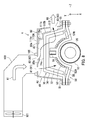
- FIG. 2 is a cross-sectional view illustrating the fixing section 4.
- the fixing section 4 includes a fixing belt 10 serving as a fixing member, a fixing roller 20, a pressure roller 30, an induction heating section 40, and a plurality of screws B1.
- the induction heating section 40 includes a coil section 50, an arched core section 70, and a cover 80.
- the induction heating section 40 inductively heats the fixing belt 10.
- the fixing belt 10 generates heat and fixes an image on a sheet P.
- the fixing belt 10 is an endless belt and disposed around the fixing roller 20 having a solid cylindrical shape.
- the fixing belt 10 for example has an inner diameter of 40 mm.
- the fixing belt 10 is for example formed from a nickel electroformed base, a silicone rubber layer formed on the base, and a release layer formed on the silicone rubber layer.
- the nickel electroformed base for example has a thickness of no less than 30 ⁇ m and no greater than 50 ⁇ m.
- the silicone rubber layer for example has a thickness of no less than 200 ⁇ m and no greater than 500 ⁇ m.
- the release layer is for example formed from a fluororesin such as perfluoroalkoxy alkane (PFA).
- PFA perfluoroalkoxy alkane
- the fixing roller 20 has a solid cylindrical shape.
- the fixing roller 20 for example has a diameter of 39.8 mm.
- the fixing roller 20 includes a solid cylindrical metal core 22 and a hollow cylindrical elastic layer 24.
- the elastic layer 24 is formed on the metal core 22.
- the metal core 22 is for example formed from stainless steel or aluminum.
- the elastic layer 24 is elastic and is for example formed from silicone rubber sponge.
- the elastic layer 24 for example has a thickness of no less than 5 mm and no greater than 10 mm.
- the pressure roller 30 has a solid cylindrical shape.
- the pressure roller 30 for example has a diameter of 35 mm.
- the pressure roller 30 includes a solid cylindrical metal core 32, a hollow cylindrical elastic layer 34, and a release layer 36.
- the elastic layer 34 is formed on the metal core 32, and the release layer 36 is formed so as to cover a surface of the elastic layer 34.
- the metal core 32 is for example formed from stainless steel or aluminum.
- the elastic layer 34 is elastic and is for example formed from silicone rubber.
- the elastic layer 34 for example has a thickness of no less than 2 mm and no greater than 5 mm.
- the release layer 36 is for example formed from a fluororesin such as PFA.
- the temperature of the pressure roller 30 is measured using a temperature measuring instrument such as a thermistor and adjusted.
- the pressure roller 30 is pressed against the fixing roller 20 with the fixing belt 10 therebetween into a pressed contact with the fixing belt 10.
- the pressure roller 30 and the fixing belt 10 form a nip N at a contact location therebetween.
- the fixing belt 10 and the fixing roller 20 passively rotate in accordance with the rotation of the pressure roller 30.
- a sheet P is conveyed in a sheet conveyance direction D1, and heat and pressure is applied onto the sheet P while the sheet P is passing through the nip N. As a result, an image is fixed onto the sheet P.
- FIG. 3 is a plan view illustrating the coil section 50. As illustrated in FIGS. 2 and 3 , the coil section 50 includes a coil 52, a center core row 54, a pair of side core rows 56, and a base section 58.
- the coil 52 is an annular coil that is formed of a conducting wire (for example, Litz wire) wound a plurality of turns and that is elongated in a direction D2 perpendicular to the sheet conveyance direction D1.
- a longitudinal direction of the coil 52 is substantially the same as the direction D2.
- the direction D2 is referred to as the longitudinal direction D2 of the coil 52.
- the coil 52 includes a first linear section 52A extending in the longitudinal direction D2 of the coil 52 and a second linear section 52B extending opposite to the first linear section 52A.
- the coil 52 is spaced a predetermined distance away from the fixing belt 10.
- the coil 52 is connected with a power supply circuit and supplied by the power supply circuit with a high frequency of alternating current to generate an alternating magnetic flux.
- the alternating magnetic flux generates eddy currents in the fixing belt 10.
- the eddy currents cause generation of Joule heat.
- the fixing belt 10 generates heat.
- a gas for example, air
- the gas that has cooled the coil 52 flows out of the induction heating section 40.
- the cooling of coil 52 will be described later.
- upstream and downstream may be used.
- upstream and downstream mean upstream and downstream in terms of the flow of the gas (air flow) used for cooling the coil 52.
- the center core row 54 is located in a region enclosed by the coil 52 in plan view.
- the center core row 54 includes a plurality of center cores 55.
- the plurality of center cores 55 are in a linear arrangement along the longitudinal direction D2 of the coil 52.
- the center cores 55 are for example formed from a magnetic material such as ferrite.
- the pair of side core rows 56 are disposed so as to have the coil 52 therebetween.
- Each of the side core rows 56 includes a plurality of side cores 57.
- the plurality of side cores 57 in each of the side core rows 56 are in a linear arrangement along the longitudinal direction D2 of the coil 52.
- the side cores 57 are for example formed from a magnetic material such as ferrite.
- the base section 58 includes a bobbin 58a, a center core holder 58b, a pair of side core holders 58c, and a pair of flat portions 58d.
- the bobbin 58a, the center core holder 58b, the pair of side core holders 58c, and the pair of flat portion 58d are for example integrally formed.
- the base section 58 is for example formed from an insulating synthetic resin.
- the bobbin 58a has a substantially C-shaped cross-section.
- the coil 52 is fixed to the bobbin 58a.
- the center core holder 58b has a substantially U-shaped cross-section and is disposed on top of the bobbin 58a.
- the center core holder 58b holds the plurality of center cores 55.
- the pair of side core holders 58c are disposed so as to have the bobbin 58a therebetween.
- Each of the side core holders 58c holds the plurality of side cores 57.
- the pair of flat portions 58d are substantially plate-shaped and are disposed so as to have the pair of side core holders 58c therebetween.
- Each of the flat portions 58d has a plurality of through holes H1.
- FIG. 4 is an exploded perspective view illustrating the arched core section 70 and the cover 80. As illustrated in FIGS. 2 to 4 , the arched core section 70 extends in the longitudinal direction D2 of the coil 52 and covers the coil 52.
- the arched core section 70 includes a plurality of arched cores 72 and an arched core holder 74.
- the plurality of arched cores 72 are arranged in the longitudinal direction D2 of the coil 52 and disposed so as to straddle the coil 52.
- the arched cores 72 are substantially C-shaped and are for example formed from a magnetic material such as ferrite.
- the magnetic flux generated from the coil 52 is guided by the arched cores 72, the center cores 55, and the side cores 57 to flow along the fixing belt 10. As a result, it is possible to effectively generate eddy currents in the fixing belt 10.
- the arched core holder 74 is for example formed from an insulating synthetic resin.
- the arched core holder 74 holds the plurality of arched cores 72. More specifically, the arched core holder 74 includes a plurality of holding portions 74a arranged along the longitudinal direction D2 of the coil 52 and a pair of flat portions 74b.
- the plurality of holding portions 74a and the pair of flat portions 74b are for example integrally formed.
- the plurality of holding portions 74a are spaced from one another.
- Each of the holding portions 74a has a substantially C-shaped cross-section and holds one arched core 72.
- the pair of flat portions 74b are substantially plate-shaped and disposed so as to have the plurality of holding portions 74a therebetween.
- Each of the flat portions 74b has a plurality of through holes H2.
- the arched core holder 74 has a plurality of fourth openings 74c. Each of the fourth openings 74c is formed between adjacent holding portions 74a. Each of the fourth openings 74c includes an upstream opening 77A and a downstream opening 77B. The upstream openings 77A are opposite to the first linear section 52A of the coil 52, and the downstream openings 77B are opposite to the second linear section 52B of the coil 52. First, second, and third openings 81, 82, and 83 will be described later.
- the cover 80 of the induction heating section 40 will be described with reference to FIGS. 2 to 4 .
- the cover 80 covers the arched core section 70.
- the cover 80 has a substantially C-shaped cross-section and is for example formed from a metal such as aluminum.
- the cover 80 blocks the magnetic flux generated from the coil 52 to prevent the magnetic flux from leaking out of the induction heating section 40. Furthermore, the cover 80 improves strength of the induction heating section 40.
- An inner surface of the cover 80 forms part of a flow channel for the gas for cooling the coil 52.
- the cover 80 has a top wall portion 80a, a side wall portion 80b, a side wall portion 80c, and a pair of flat portions 80d.
- the top wall portion 80a, the side wall portion 80b, the side wall portion 80c, and the pair of flat portions 80d are for example integrally formed.
- the pair of flat portions 80d are substantially plate-shaped and constitute a pair of side edges of the cover 80.
- Each of the flat portions 80d has a plurality of through holes H3.
- Each of the screws B1 ( FIG. 2 ) is inserted into one of the through holes H3, one of the through holes H2 of the arched core holder 74, and one of the through holes H1 of the base section 58, so that the cover 80, the arched core section 70, and the coil section 50 are tightened to one another.
- the induction heating section 40 has a unitized configuration.
- the induction heating section 40 is fixed inside the image forming apparatus 100.
- the cover 80 has a first opening row 91, a second opening row 92, and a third opening row 93.
- the first opening row 91 and the second opening row 92 are formed in the top wall portion 80a.
- the third opening row 93 is formed in the side wall portion 80b. Both the first opening row 91 and the second opening row 92 are located at a side closer to the first linear section 52A of the coil 52 than a center line C ( FIG. 3 ) of the coil 52 in the longitudinal direction D2.
- the second opening row 92 is located closer to the second linear section 52B of the coil 52 than the first opening row 91.
- the third opening row 93 is located at a side closer to the second linear section 52B than the center line C of the coil 52.
- the second opening row 92 is located between the first opening row 91 and the third opening row 93.
- the first opening row 91 includes the plurality of first openings 81 arranged in the longitudinal direction D2 of the coil 52.
- the second opening row 92 includes the plurality of second openings 82 arranged in the longitudinal direction D2 of the coil 52.
- the third opening row 93 is formed in the side wall portion 80b.
- the third opening row 93 includes the plurality of third openings 83 arranged in the longitudinal direction D2 of the coil 52.
- a gas (for example, air) that is used for cooling the coil 52 is sent toward the first openings 81 and the second openings 82.
- the gas sent toward the first openings 81 and the second openings 82 flows into the induction heating section 40, passes through the upstream openings 77A and the downstream openings 77B, and flows out through the third openings 83.
- the coil 52 is cooled by the gas that flows in through the first openings 81 and the second openings 82 and that flows out through the third openings 83.
- the gas is sent to the first linear section 52A of the coil 52 through the first openings 81 thereby to cool the first linear section 52A. Furthermore, the gas is sent to the second linear section 52B of the coil 52 through the second openings 82 thereby to cool the second linear section 52B. It is therefore possible to cool the coil 52 while also preventing a difference in temperature from occurring between the first linear section 52A and the second linear section 52B.
- FIG. 5 is a cross-sectional view illustrating flows of the gas for cooling the coil 52.
- the fixing section 4 further includes an intake section 101 serving as a blower, a duct 103, and a seal 105.
- the intake section 101 for example includes a fan and takes in a gas (for example, air) from the outside of the image forming apparatus 100 to send gas A1 to the duct 103.
- the duct 103 is connected with the cover 80 with the seal 105 therebetween so as to cover the first opening row 91 and the second opening row 92.
- the duct 103 guides the gas A1 from the intake section 101 to the first openings 81 forming the first opening row 91 and to the second openings 82 forming the second opening row 92.
- the seal 105 is for example formed from sponge.
- the seal 105 is for example in the shape of a rectangular toroid enclosing the first opening row 91 and the second opening row 92.
- the gas A1 sent to the first openings 81 is to mainly cool the first linear section 52A of the coil 52. That is, the gas A1 sent to the first openings 81 is blown as gas A2 to the first linear section 52A. The gas A2 then cools the first linear section 52A and flows as gas A3 toward the third openings 83. In this case, the gas A3 flows toward the third openings 83 after passing the coil 52 and the center cores 55.
- First guides 80e will be described before describing the gas A1 sent to the second openings 82.
- the cover 80 includes the first guides 80e.
- the first guides 80e are plate-shaped and are located at the respective second openings 82. More specifically, each of the first guides 80e extends from a section of an opening edge of a corresponding one of the second openings 82 that is farthest from the third openings 83.
- Each of the first guides 80e is inclined toward an interior of the cover 80 at an acute angle relative to the corresponding one of the second openings 82.
- Each of the first guides 80e is for example formed by bending a portion of the cover 80.
- the gas A1 sent to the second openings 82 is to mainly cool the second linear section 52B of the coil 52. That is, the gas A1 sent to the second openings 85 is guided as gas A4 by the first guides 80e to the second linear section 52B of the coil 52 through the fourth openings 74c ( FIG. 4 ). The gas A4 then cools the second linear section 52B and flows toward the third openings 83.
- the gas A1 sent to the second openings 82 is guided by the first guides 80e to an inner surface S of the side wall portion 80b of the cover 80, hits the inner surface S to be blown as gas A5 to the second linear section 52B through the downstream openings 77B ( FIG. 4 ). The gas A5 then cools the second linear section 52B and flows toward the third openings 83.
- the gas A3 that has cooled the first linear section 52A, the gas A4 that has cooled the second linear section 52B, and the gas A5 that has cooled the second linear section 52B unite together and flow out as gas A6 through the third openings 83.
- FIG. 6 is a plan view illustrating arrangement of the first to third openings 81 to 83.
- FIG. 6 illustrates the arched core section 70 viewed from a side of the coil 52 ( FIG. 2 ) and also illustrates an outer surface of the cover 80.
- the first openings 81 are located opposite to the holding portions 74a. That is, the first openings 81 are located opposite to the arched cores 72 with the holding portions 74a therebetween.
- the second openings 82 are located opposite to the fourth openings 74c. More specifically, the second openings 82 are located opposite to the upstream openings 77A.
- the third openings 83 are located opposite to the holding portions 74a. That is, the third openings 83 are located opposite to the arched cores 72 with the holding portions 74a therebetween.
- a length L1 of each first opening 81, a length L2 of each second opening 82, and a length L3 of each third opening 83 are determined according to a width Wa of each arched core 72 and a distance Wb between adjacent arched cores 72.
- the length L1, the length L2, and the length L3 represent a dimension of each first opening 81, a dimension of each second opening 82, and a dimension of each third opening 83, respectively, in the longitudinal direction D2 of the coil 52.
- the width Wa represents a dimension of each arched core 72 in the longitudinal direction D2 of the coil 52.
- a width W1 of each first opening 81, a width W2 of each second opening 82, and a width W3 of each third opening 83 are determined based on a shape of the cover 80.
- the width W1 is preferably smaller than the width W2.
- the width W1, the width W2, and the width W3 represent a dimension of each first opening 81, a dimension of each second opening 82, and a dimension of each third opening 83, respectively, in the sheet conveyance direction D1.
- the length L1 is no less than 10 mm and no greater than 20 mm
- the width W1 is no less than 5 mm and no greater than 10 mm
- the length L2 is no less than 10 mm and no greater than 20 mm
- the width W2 is no less than 10 mm and no greater than 15 mm
- the length L3 is no less than 10 mm and no greater than 20 mm
- the width W3 is no less than 10 mm and no greater than 20 mm.
- the first linear section 52A is cooled by the gas from the first openings 81
- the second linear section 52B is cooled by the gas from the second openings 82. It is therefore possible to cool the coil 52 while also preventing a difference in temperature from occurring between the first linear section 52A and the second linear section 52B. That is, it is possible to cool the coil 52 while also preventing a difference in temperature from occurring in the coil 52.
- the second openings 82 are located at the side closer to the first linear section 52A of the coil 52 than the center line C of the coil 52 in the longitudinal direction D2.
- Each of the second openings 82 can therefore be restricted to a smaller area compared to the configuration in which each of the second openings spans across the center line C. It is therefore possible to restrict reduction of the strength of the cover 80 while restricting leakage of the magnetic flux.
- the first guides 80e are farther from the center cores 55 and the coil 52 compared to the configuration in which each of the second openings spans across the center line C. It is therefore possible to prevent the first guides 80e from contacting the center cores 55 and the coil 52, ensuring a sufficient distance for insulation.
- the first guides 80e guide the gas sent to the second openings 82 to a space in which the second linear section 52B of the coil 52 is placed. It is therefore possible to effectively cool the second linear section 52B and further prevent a difference in temperature from occurring between the first linear section 52A and the second linear section 52B.
- the intake section 101 sends the gas toward the first openings 81 and the second openings 82. It is therefore possible to cause the gas to effectively flow from the first openings 81 and the second openings 82 toward the coil 52.
- the first openings 81 are located opposite to the holding portions 74a.
- the gas from the first openings 81 is therefore blown to the first linear section 52A via the holding portions 74a. It is therefore possible to prevent the first linear section 52A from being excessively cooled and prevent a situation in which the second linear section 52B is hard to cool due to the gas that has received heat from the first linear section 52A.
- the first openings 81 have a smaller area than the second openings 82. This configuration restricts the gas that flows from the first openings 81 toward the first linear section 52A to a smaller amount. It is therefore possible to prevent the first linear section 52A from being excessively cooled and prevent a situation in which the second linear section 52B is hard to cool due to the gas that has received heat from the first linear section 52A.
- the second openings 82 are located opposite to the fourth openings 74c. It is therefore possible to effectively send the gas from the second openings 82 to the second linear section 52B through the fourth openings 74c.
- the second openings 82 are located opposite to the fourth openings 74c and the third openings 83 are located opposite to the holding portions 74a.
- the gas sent through the second openings 82 therefore passes through the fourth openings 74c and hits the inner surface S ( FIG. 5 ) of the cover 80 to be guided to the second linear section 52B. It is therefore possible to further effectively cool the second linear section 52B and further prevent a difference in temperature from occurring between the first linear section 52A and the second linear section 52B.
- the image forming apparatus 100 and the fixing section 4 according to a second embodiment of the present disclosure will be described with reference to FIGS. 1 to 3, 5, and 7 to 9 .
- the image forming apparatus 100 according to the second embodiment has a similar configuration to the image forming apparatus 100 according to the first embodiment illustrated in FIG. 1 .
- the fixing section 4 according to the second embodiment has a similar configuration to the fixing section 4 according to the first embodiment illustrated in FIGS. 2 , 3 , and 5 .
- the fixing section 4 according to the second embodiment is different from the fixing section 4 according to the first embodiment in that the fixing section 4 according to the second embodiment includes a second guide 110A. The following mainly describes differences between the second embodiment and the first embodiment.
- FIG. 7 is an exploded perspective view illustrating the arched core section 70, the second guide 110A, and the cover 80 of the fixing section 4 according to the second embodiment.
- the fixing section 4 further includes the second guide 110A.
- the second guide 110A is disposed between the arched core section 70 and the cover 80, and elongated in the longitudinal direction D2 of the coil 52 ( FIG. 3 ).
- the second guide 110A has a first wall portion 110a, a second wall portion 110b, an upper stage portion 111a, and a lower stage portion 111b. Both the first wall portion 110a and the second wall portion 110b extend in the longitudinal direction D2 of the coil 52.
- the second wall portion 110b has a plurality of fifth openings 115 corresponding to the plurality of third openings 83 in the cover 80.
- the cover 80 covers the second guide 110A and the arched core section 70 such that the third openings 83 overlap the fifth openings 115.
- the upper stage portion 111a extends from an upper edge of the first wall portion 110a at an angle thereto.
- the upper stage portion 111a has a flat top surface.
- the lower stage portion 111b connects a lower edge of the first wall portion 110a with an upper edge of the second wall portion 110b.
- the lower stage portion 111a has a flat bottom surface.
- FIG. 8 is a cross-sectional view illustrating the second guide 110A and flows of gas for cooling the coil 52.
- the first linear section 52A of the coil 52 is cooled in the same manner as in the cooling of the first linear section 52A described with reference to FIG. 5 .
- the gas A3 and the gas A4 illustrated in FIG. 5 are not illustrated in FIG. 8 in the interest of ease of illustration.
- the gas A7 is thus blown to the second linear section 52B, cools the second linear section 52B, and flows toward the third openings 83.
- the gas A3 ( FIG. 5 ) that has cooled the first linear section 52A, the gas A4 ( FIG. 5 ) that has cooled the second linear section 52B, and the gas A7 that has cooled the second linear section 52B unite together and flow out as gas A7 through the third openings 83.
- the second guide 110A is disposed between the cover 80 and the arched core holder 74, and is fixed by the cover 80, the arched core holder 74, and the base section 58 tightened to one another with the screws B1.
- the top surface of the upper stage portion 111a of the second guide 110A is restrained by a lower surface of the top wall portion 80a of the cover 80
- the bottom surface of the lower stage portion 111b of the second guide 110A is restrained by top surfaces of the holding portions 74a of the arched core holder 74.
- An end of the second guide 110A in the longitudinal direction is restrained by a rib formed in the arched core holder 74 and/or an abutment portion formed in a longitudinal end of the cover 80.
- FIG. 9 is a plan view illustrating arrangement of the first to third openings 81 to 83.
- FIG. 9 illustrates the arched core section 70 viewed from the side of the coil 52 ( FIG. 8 ), an outer surface of the second guide 110A, and the outer surface of the cover 80.
- the first openings 81 are arranged in the same manner as in the arrangement of the first openings 81 according to the first embodiment illustrated in FIG. 6 .
- the second openings 82 are arranged in the same manner as in the arrangement of the second openings 82 according to the first embodiment illustrated in FIG. 6 .
- the third openings 83 and the fifth openings 115 are located opposite to the fourth openings 74c. More specifically, the third openings 83 and the fifth openings 115 are located opposite to the downstream openings 77B.
- the fifth openings 115 for example each have substantially the same area as the third openings 83 or have a larger area than the third openings 83.
- the length L1 and the width W1 of each first opening 81, the length L2 and the width W2 of each second opening 82, the length L3 and the width W3 of each third opening 83, the width Wa of each arched core 72, and the distance Wb between adjacent arched cores 72 are determined in the same manner as for the length L1 and the width W1, the length L2 and the width W2, the length L3 and the width W3, the width Wa, and the distance Wb according to the first embodiment illustrated in FIG. 6 .
- the second guide 110A guides the gas coming through the second openings 82 to the second linear section 52B. It is therefore possible to efficiently blow the gas sent through the second openings 82 to the second linear section 52B. As a result, the effect of cooling the second linear section 52B is improved. Since the second embodiment also includes the first openings 81 and the second openings 82, it is possible to cool the coil 52 while also preventing a difference in temperature from occurring in the coil 52 as in the case of the first embodiment. Other than that, the fixing section 4 according to the second embodiment has the same effects as the fixing section 4 according to the first embodiment.
- the image forming apparatus 100 and the fixing section 4 according to a third embodiment of the present disclosure will be described with reference to FIG. 10 .
- the image forming apparatus 100 according to the third embodiment has a similar configuration to the image forming apparatus 100 according to the second embodiment.
- the fixing section 4 according to the third embodiment has a similar configuration to the fixing section 4 according to the second embodiment.
- the third embodiment includes a second guide 110B instead of the second guide 110A according to the second embodiment. The following mainly describes differences between the third embodiment and the second embodiment.
- FIG. 10 is a cross-sectional view illustrating the second guide 110B and flows of gas for cooling the coil 52.
- the gas A3 and the gas A4 illustrated in FIG. 5 are not illustrated in FIG. 10 in the interest of ease of illustration.
- the fixing section 4 includes the second guide 110B instead of the second guide 110A and further includes a plurality of screws B2.
- the second guide 110B has a substantially L-shaped cross-section and includes a wall portion 119a and a flat portion 119b.
- the second guide 110B is fixed to the cover 80 by the flat portion 119b tightened to the cover 80 with the screws B2.
- the second guide 110B is elongated in the longitudinal direction D2 ( FIG. 3 ) of the coil 52.
- the gas A1 sent to the second openings 82 and guided as the gas A7 to the second guide 110B by the first guides 80e hits the wall portion 119a of the second guide 110B to be guided to the second linear section 52B of the coil 52 through the downstream openings 77B ( FIG. 7 ).
- the gas A7 is thus blown to the second linear section 52B, cools the second linear section 52B, and flows toward the third openings 83.
- the second guide 110B guides the gas coming through the second openings 82 to the second linear section 52B. It is therefore possible to efficiently blow the gas sent through the second openings 82 to the second linear section 52B. As a result, the effect of cooling the second linear section 52B is improved. Since the third embodiment also includes the first openings 81 and the second openings 82, it is possible to cool the coil 52 while also preventing a difference in temperature from occurring in the coil 52 as in the case of the first embodiment. Other than that, the fixing section 4 according to the third embodiment has the same effects as the fixing section 4 according to the first embodiment.
- the present disclosure relates to fixing devices and image forming apparatuses and has industrial applicability.
Landscapes
- Physics & Mathematics (AREA)
- General Physics & Mathematics (AREA)
- Fixing For Electrophotography (AREA)
- General Induction Heating (AREA)
Abstract
Description
- The present disclosure relates to a fixing device and an image forming apparatus.
- One example of a fixing device includes a fixing roller, an annular coil that inductively heats the fixing roller, a plurality of magnetic cores that covers the coil, a holding section that holds the plurality of magnetic cores, and a shield member that covers the holding section. The holding section includes a plurality of core receiving sections, a plurality of first openings, and a plurality of second openings. The magnetic cores are disposed in the respective core receiving sections. One first opening forms a pair with one second opening, and each pair is located between adjacent two core receiving sections.
- The shield member has a plurality of air inlets, and a plurality of air outlets. The air inlets are located opposite to the respective first openings, and the air outlets are located opposite to the respective second openings. Air introduced through the air inlets passes through the first openings and the second openings, and then released from the air outlets. The coil is cooled by the air introduced through the air inlets.
- A fixing device according to a first aspect of the present disclosure includes a fixing member and an induction heating section. The fixing member fixes an image onto a sheet. The induction heating section inductively heats the fixing member. The induction heating section includes an annular coil, an arched core section, and a cover. The annular coil is elongated in a direction perpendicular to a conveyance direction of the sheet. The arched core section includes a plurality of arched cores. The plurality of arched cores are arranged in a longitudinal direction of the annular coil and disposed so as to straddle the annular coil. The cover covers the arched core section. The cover has a first opening row, a second opening row, and a third opening row. The first opening row includes a plurality of first openings. The plurality of first openings are arranged in the longitudinal direction of the annular coil. The second opening row includes a plurality of second openings. The plurality of second openings are arranged in the longitudinal direction of the annular coil. The third opening row includes a plurality of third openings. The plurality of third openings are arranged in the longitudinal direction of the annular coil. The annular coil includes a first linear section and a second linear section. The first linear section extends in the longitudinal direction of the annular coil. The second linear section extends opposite to the first linear section. Both the first opening row and the second opening row are located at a side closer to the first linear section than a center line of the annular coil in the longitudinal direction. The second opening row is located closer to the second linear section than the first opening row. The third opening row is located at a side closer to the second linear section than the center line.
- An image forming apparatus according to a second aspect of the present disclosure includes the fixing device according to the first aspect and an image forming section that forms an image on a sheet.
-
-
FIG. 1 is a cross-sectional view illustrating an image forming apparatus according to a first embodiment of the present disclosure. -
FIG. 2 is a cross-sectional view illustrating a fixing section of the image forming apparatus according to the first embodiment of the present disclosure. -
FIG. 3 is a plan view illustrating a coil section of the image forming apparatus according to the first embodiment of the present disclosure. -
FIG. 4 is an exploded perspective view illustrating an arched core section and a cover of the image forming apparatus according to the first embodiment of the present disclosure. -
FIG. 5 is a cross-sectional view illustrating flows of gas for cooling a coil of the image forming apparatus according to the first embodiment of the present disclosure. -
FIG. 6 is a plan view illustrating arrangement of first to third openings of the image forming apparatus according to the first embodiment of the present disclosure. -
FIG. 7 is an exploded perspective view illustrating an arched core section, a second guide, and a cover of an image forming apparatus according to a second embodiment of the present disclosure. -
FIG. 8 is a cross-sectional view illustrating flows of gas for cooling a coil of the image forming apparatus according to the second embodiment of the present disclosure. -
FIG. 9 is a plan view illustrating arrangement of first to third openings of the image forming apparatus according to the second embodiment of the present disclosure. -
FIG. 10 is a cross-sectional view illustrating flows of gas for cooling a coil of an image forming apparatus according to a third embodiment of the present disclosure. - The following describes embodiments of the present disclosure with reference to the accompanying drawings. Elements in the drawings that are the same or equivalent are marked by the same reference sign and the description thereof is not repeated. In the embodiments, an X axis, a Y axis, and a Z axis are perpendicular to one another. The X axis and the Y axis are parallel to a horizontal plane. The Z axis is parallel to a vertical line.
- An
image forming apparatus 100 according to a first embodiment of the present disclosure will be described with reference toFIG. 1. FIG. 1 is a cross-sectional view illustrating theimage forming apparatus 100. Theimage forming apparatus 100 is a color printer. Theimage forming apparatus 100 includes a feed section 1, aconveyance section 2, animage forming section 3, afixing section 4 serving as a fixing device, and anejecting section 5. - The feed section 1 accommodates a plurality of sheets P and conveys the sheets to the
conveyance section 2. The sheets P are for example paper or synthetic resin sheets. Theconveyance section 2 includes a plurality of conveyance rollers and conveys a sheet P to theimage forming section 3. Theimage forming section 3 forms an image on a sheet P by electrophotography. Theconveyance section 2 conveys the sheet P having the image formed thereon to thefixing section 4. Thefixing section 4 applies heat and pressure to the image formed on the sheet P to fix the image onto the sheet P. Theconveyance section 2 conveys the sheet P having the image fixed thereon to theejecting section 5. The ejectingsection 5 ejects the sheet P out of theimage forming apparatus 100. - The
fixing section 4 will be described with reference toFIG. 2. FIG. 2 is a cross-sectional view illustrating thefixing section 4. The fixingsection 4 includes a fixingbelt 10 serving as a fixing member, a fixingroller 20, apressure roller 30, aninduction heating section 40, and a plurality of screws B1. Theinduction heating section 40 includes acoil section 50, anarched core section 70, and acover 80. - The
induction heating section 40 inductively heats the fixingbelt 10. As a result of the induction heating, the fixingbelt 10 generates heat and fixes an image on a sheet P. The fixingbelt 10 is an endless belt and disposed around the fixingroller 20 having a solid cylindrical shape. The fixingbelt 10 for example has an inner diameter of 40 mm. The fixingbelt 10 is for example formed from a nickel electroformed base, a silicone rubber layer formed on the base, and a release layer formed on the silicone rubber layer. The nickel electroformed base for example has a thickness of no less than 30 µm and no greater than 50 µm. The silicone rubber layer for example has a thickness of no less than 200 µm and no greater than 500 µm. The release layer is for example formed from a fluororesin such as perfluoroalkoxy alkane (PFA). The temperature of the fixingbelt 10 is measured using a temperature measuring instrument such as a thermistor and adjusted. - The fixing
roller 20 has a solid cylindrical shape. The fixingroller 20 for example has a diameter of 39.8 mm. The fixingroller 20 includes a solidcylindrical metal core 22 and a hollow cylindricalelastic layer 24. Theelastic layer 24 is formed on themetal core 22. Themetal core 22 is for example formed from stainless steel or aluminum. Theelastic layer 24 is elastic and is for example formed from silicone rubber sponge. Theelastic layer 24 for example has a thickness of no less than 5 mm and no greater than 10 mm. - The
pressure roller 30 has a solid cylindrical shape. Thepressure roller 30 for example has a diameter of 35 mm. Thepressure roller 30 includes a solidcylindrical metal core 32, a hollow cylindricalelastic layer 34, and arelease layer 36. Theelastic layer 34 is formed on themetal core 32, and therelease layer 36 is formed so as to cover a surface of theelastic layer 34. Themetal core 32 is for example formed from stainless steel or aluminum. Theelastic layer 34 is elastic and is for example formed from silicone rubber. Theelastic layer 34 for example has a thickness of no less than 2 mm and no greater than 5 mm. Therelease layer 36 is for example formed from a fluororesin such as PFA. The temperature of thepressure roller 30 is measured using a temperature measuring instrument such as a thermistor and adjusted. - The
pressure roller 30 is pressed against the fixingroller 20 with the fixingbelt 10 therebetween into a pressed contact with the fixingbelt 10. Thepressure roller 30 and the fixingbelt 10 form a nip N at a contact location therebetween. Upon driving and rotation of thepressure roller 30, the fixingbelt 10 and the fixingroller 20 passively rotate in accordance with the rotation of thepressure roller 30. A sheet P is conveyed in a sheet conveyance direction D1, and heat and pressure is applied onto the sheet P while the sheet P is passing through the nip N. As a result, an image is fixed onto the sheet P. - The
coil section 50 of theinduction heating section 40 will be described with reference toFIGS. 2 and3. FIG. 3 is a plan view illustrating thecoil section 50. As illustrated inFIGS. 2 and3 , thecoil section 50 includes acoil 52, acenter core row 54, a pair ofside core rows 56, and abase section 58. - The
coil 52 is an annular coil that is formed of a conducting wire (for example, Litz wire) wound a plurality of turns and that is elongated in a direction D2 perpendicular to the sheet conveyance direction D1. A longitudinal direction of thecoil 52 is substantially the same as the direction D2. Hereinafter, the direction D2 is referred to as the longitudinal direction D2 of thecoil 52. Thecoil 52 includes a firstlinear section 52A extending in the longitudinal direction D2 of thecoil 52 and a secondlinear section 52B extending opposite to the firstlinear section 52A. - The
coil 52 is spaced a predetermined distance away from the fixingbelt 10. Thecoil 52 is connected with a power supply circuit and supplied by the power supply circuit with a high frequency of alternating current to generate an alternating magnetic flux. The alternating magnetic flux generates eddy currents in the fixingbelt 10. The eddy currents cause generation of Joule heat. Thus, the fixingbelt 10 generates heat. - Since the
coil 52 generates heat, a gas (for example, air) is introduced into theinduction heating section 40 to cool thecoil 52. The gas that has cooled thecoil 52 flows out of theinduction heating section 40. The cooling ofcoil 52 will be described later. Hereinafter, the terms "upstream" and "downstream" may be used. The terms "upstream" and "downstream" mean upstream and downstream in terms of the flow of the gas (air flow) used for cooling thecoil 52. - The
center core row 54 is located in a region enclosed by thecoil 52 in plan view. Thecenter core row 54 includes a plurality ofcenter cores 55. The plurality ofcenter cores 55 are in a linear arrangement along the longitudinal direction D2 of thecoil 52. Thecenter cores 55 are for example formed from a magnetic material such as ferrite. - The pair of
side core rows 56 are disposed so as to have thecoil 52 therebetween. Each of theside core rows 56 includes a plurality ofside cores 57. The plurality ofside cores 57 in each of theside core rows 56 are in a linear arrangement along the longitudinal direction D2 of thecoil 52. Theside cores 57 are for example formed from a magnetic material such as ferrite. - The
base section 58 includes abobbin 58a, acenter core holder 58b, a pair ofside core holders 58c, and a pair offlat portions 58d. Thebobbin 58a, thecenter core holder 58b, the pair ofside core holders 58c, and the pair offlat portion 58d are for example integrally formed. - The
base section 58 is for example formed from an insulating synthetic resin. Thebobbin 58a has a substantially C-shaped cross-section. Thecoil 52 is fixed to thebobbin 58a. Thecenter core holder 58b has a substantially U-shaped cross-section and is disposed on top of thebobbin 58a. Thecenter core holder 58b holds the plurality ofcenter cores 55. The pair ofside core holders 58c are disposed so as to have thebobbin 58a therebetween. Each of theside core holders 58c holds the plurality ofside cores 57. The pair offlat portions 58d are substantially plate-shaped and are disposed so as to have the pair ofside core holders 58c therebetween. Each of theflat portions 58d has a plurality of through holes H1. - The
arched core section 70 of theinduction heating section 40 will be described with reference toFIGS. 2 to 4 .FIG. 4 is an exploded perspective view illustrating thearched core section 70 and thecover 80. As illustrated inFIGS. 2 to 4 , thearched core section 70 extends in the longitudinal direction D2 of thecoil 52 and covers thecoil 52. Thearched core section 70 includes a plurality ofarched cores 72 and anarched core holder 74. - The plurality of
arched cores 72 are arranged in the longitudinal direction D2 of thecoil 52 and disposed so as to straddle thecoil 52. Thearched cores 72 are substantially C-shaped and are for example formed from a magnetic material such as ferrite. The magnetic flux generated from thecoil 52 is guided by thearched cores 72, thecenter cores 55, and theside cores 57 to flow along the fixingbelt 10. As a result, it is possible to effectively generate eddy currents in the fixingbelt 10. - The
arched core holder 74 is for example formed from an insulating synthetic resin. Thearched core holder 74 holds the plurality ofarched cores 72. More specifically, thearched core holder 74 includes a plurality of holdingportions 74a arranged along the longitudinal direction D2 of thecoil 52 and a pair offlat portions 74b. The plurality of holdingportions 74a and the pair offlat portions 74b are for example integrally formed. The plurality of holdingportions 74a are spaced from one another. Each of the holdingportions 74a has a substantially C-shaped cross-section and holds onearched core 72. The pair offlat portions 74b are substantially plate-shaped and disposed so as to have the plurality of holdingportions 74a therebetween. Each of theflat portions 74b has a plurality of through holes H2. - The
arched core holder 74 has a plurality offourth openings 74c. Each of thefourth openings 74c is formed between adjacent holdingportions 74a. Each of thefourth openings 74c includes anupstream opening 77A and adownstream opening 77B. Theupstream openings 77A are opposite to the firstlinear section 52A of thecoil 52, and thedownstream openings 77B are opposite to the secondlinear section 52B of thecoil 52. First, second, andthird openings - Next, the
cover 80 of theinduction heating section 40 will be described with reference toFIGS. 2 to 4 . As illustrated inFIGS. 2 to 4 , thecover 80 covers thearched core section 70. Thecover 80 has a substantially C-shaped cross-section and is for example formed from a metal such as aluminum. Thecover 80 blocks the magnetic flux generated from thecoil 52 to prevent the magnetic flux from leaking out of theinduction heating section 40. Furthermore, thecover 80 improves strength of theinduction heating section 40. An inner surface of thecover 80 forms part of a flow channel for the gas for cooling thecoil 52. - The
cover 80 has atop wall portion 80a, aside wall portion 80b, aside wall portion 80c, and a pair offlat portions 80d. Thetop wall portion 80a, theside wall portion 80b, theside wall portion 80c, and the pair offlat portions 80d are for example integrally formed. - The pair of
flat portions 80d are substantially plate-shaped and constitute a pair of side edges of thecover 80. Each of theflat portions 80d has a plurality of through holes H3. Each of the screws B1 (FIG. 2 ) is inserted into one of the through holes H3, one of the through holes H2 of thearched core holder 74, and one of the through holes H1 of thebase section 58, so that thecover 80, thearched core section 70, and thecoil section 50 are tightened to one another. As a result, theinduction heating section 40 has a unitized configuration. Theinduction heating section 40 is fixed inside theimage forming apparatus 100. - The
cover 80 has afirst opening row 91, asecond opening row 92, and athird opening row 93. Thefirst opening row 91 and thesecond opening row 92 are formed in thetop wall portion 80a. Thethird opening row 93 is formed in theside wall portion 80b. Both thefirst opening row 91 and thesecond opening row 92 are located at a side closer to the firstlinear section 52A of thecoil 52 than a center line C (FIG. 3 ) of thecoil 52 in the longitudinal direction D2. Thesecond opening row 92 is located closer to the secondlinear section 52B of thecoil 52 than thefirst opening row 91. Thethird opening row 93 is located at a side closer to the secondlinear section 52B than the center line C of thecoil 52. Thus, thesecond opening row 92 is located between thefirst opening row 91 and thethird opening row 93. - The
first opening row 91 includes the plurality offirst openings 81 arranged in the longitudinal direction D2 of thecoil 52. Thesecond opening row 92 includes the plurality ofsecond openings 82 arranged in the longitudinal direction D2 of thecoil 52. Thethird opening row 93 is formed in theside wall portion 80b. Thethird opening row 93 includes the plurality ofthird openings 83 arranged in the longitudinal direction D2 of thecoil 52. - A gas (for example, air) that is used for cooling the
coil 52 is sent toward thefirst openings 81 and thesecond openings 82. The gas sent toward thefirst openings 81 and thesecond openings 82 flows into theinduction heating section 40, passes through theupstream openings 77A and thedownstream openings 77B, and flows out through thethird openings 83. Thecoil 52 is cooled by the gas that flows in through thefirst openings 81 and thesecond openings 82 and that flows out through thethird openings 83. - More specifically, the gas is sent to the first
linear section 52A of thecoil 52 through thefirst openings 81 thereby to cool the firstlinear section 52A. Furthermore, the gas is sent to the secondlinear section 52B of thecoil 52 through thesecond openings 82 thereby to cool the secondlinear section 52B. It is therefore possible to cool thecoil 52 while also preventing a difference in temperature from occurring between the firstlinear section 52A and the secondlinear section 52B. - Flows of the gas for cooling the
coil 52 will be described with reference toFIG. 5. FIG. 5 is a cross-sectional view illustrating flows of the gas for cooling thecoil 52. The fixingsection 4 further includes anintake section 101 serving as a blower, aduct 103, and aseal 105. Theintake section 101 for example includes a fan and takes in a gas (for example, air) from the outside of theimage forming apparatus 100 to send gas A1 to theduct 103. Theduct 103 is connected with thecover 80 with theseal 105 therebetween so as to cover thefirst opening row 91 and thesecond opening row 92. Theduct 103 guides the gas A1 from theintake section 101 to thefirst openings 81 forming thefirst opening row 91 and to thesecond openings 82 forming thesecond opening row 92. Theseal 105 is for example formed from sponge. Theseal 105 is for example in the shape of a rectangular toroid enclosing thefirst opening row 91 and thesecond opening row 92. - The gas A1 sent to the
first openings 81 is to mainly cool the firstlinear section 52A of thecoil 52. That is, the gas A1 sent to thefirst openings 81 is blown as gas A2 to the firstlinear section 52A. The gas A2 then cools the firstlinear section 52A and flows as gas A3 toward thethird openings 83. In this case, the gas A3 flows toward thethird openings 83 after passing thecoil 52 and thecenter cores 55. -
First guides 80e will be described before describing the gas A1 sent to thesecond openings 82. As illustrated inFIGS. 4 and5 , thecover 80 includes thefirst guides 80e. Thefirst guides 80e are plate-shaped and are located at the respectivesecond openings 82. More specifically, each of thefirst guides 80e extends from a section of an opening edge of a corresponding one of thesecond openings 82 that is farthest from thethird openings 83. Each of thefirst guides 80e is inclined toward an interior of thecover 80 at an acute angle relative to the corresponding one of thesecond openings 82. Each of thefirst guides 80e is for example formed by bending a portion of thecover 80. - The gas A1 sent to the
second openings 82 is to mainly cool the secondlinear section 52B of thecoil 52. That is, the gas A1 sent to the second openings 85 is guided as gas A4 by thefirst guides 80e to the secondlinear section 52B of thecoil 52 through thefourth openings 74c (FIG. 4 ). The gas A4 then cools the secondlinear section 52B and flows toward thethird openings 83. The gas A1 sent to thesecond openings 82 is guided by thefirst guides 80e to an inner surface S of theside wall portion 80b of thecover 80, hits the inner surface S to be blown as gas A5 to the secondlinear section 52B through thedownstream openings 77B (FIG. 4 ). The gas A5 then cools the secondlinear section 52B and flows toward thethird openings 83. - The gas A3 that has cooled the first
linear section 52A, the gas A4 that has cooled the secondlinear section 52B, and the gas A5 that has cooled the secondlinear section 52B unite together and flow out as gas A6 through thethird openings 83. - Arrangement of the first to
third openings 81 to 83 will be described with reference toFIG. 6. FIG. 6 is a plan view illustrating arrangement of the first tothird openings 81 to 83.FIG. 6 illustrates thearched core section 70 viewed from a side of the coil 52 (FIG. 2 ) and also illustrates an outer surface of thecover 80. - The
first openings 81 are located opposite to the holdingportions 74a. That is, thefirst openings 81 are located opposite to thearched cores 72 with the holdingportions 74a therebetween. Thesecond openings 82 are located opposite to thefourth openings 74c. More specifically, thesecond openings 82 are located opposite to theupstream openings 77A. Thethird openings 83 are located opposite to the holdingportions 74a. That is, thethird openings 83 are located opposite to thearched cores 72 with the holdingportions 74a therebetween. - A length L1 of each
first opening 81, a length L2 of eachsecond opening 82, and a length L3 of eachthird opening 83 are determined according to a width Wa of eacharched core 72 and a distance Wb between adjacentarched cores 72. The length L1, the length L2, and the length L3 represent a dimension of eachfirst opening 81, a dimension of eachsecond opening 82, and a dimension of eachthird opening 83, respectively, in the longitudinal direction D2 of thecoil 52. The width Wa represents a dimension of eacharched core 72 in the longitudinal direction D2 of thecoil 52. - A width W1 of each
first opening 81, a width W2 of eachsecond opening 82, and a width W3 of eachthird opening 83 are determined based on a shape of thecover 80. The width W1 is preferably smaller than the width W2. The width W1, the width W2, and the width W3 represent a dimension of eachfirst opening 81, a dimension of eachsecond opening 82, and a dimension of eachthird opening 83, respectively, in the sheet conveyance direction D1. - In a configuration in which the width Wa is 10 mm and the width Wb is 20 mm, for example, the length L1 is no less than 10 mm and no greater than 20 mm, the width W1 is no less than 5 mm and no greater than 10 mm, the length L2 is no less than 10 mm and no greater than 20 mm, the width W2 is no less than 10 mm and no greater than 15 mm, the length L3 is no less than 10 mm and no greater than 20 mm, and the width W3 is no less than 10 mm and no greater than 20 mm.
- According to the first embodiment, as described above with reference to
FIGS. 2 to 4 , the firstlinear section 52A is cooled by the gas from thefirst openings 81, and the secondlinear section 52B is cooled by the gas from thesecond openings 82. It is therefore possible to cool thecoil 52 while also preventing a difference in temperature from occurring between the firstlinear section 52A and the secondlinear section 52B. That is, it is possible to cool thecoil 52 while also preventing a difference in temperature from occurring in thecoil 52. - According to the first embodiment, as described above with reference to
FIGS. 3 and4 , thesecond openings 82 are located at the side closer to the firstlinear section 52A of thecoil 52 than the center line C of thecoil 52 in the longitudinal direction D2. Each of thesecond openings 82 can therefore be restricted to a smaller area compared to the configuration in which each of the second openings spans across the center line C. It is therefore possible to restrict reduction of the strength of thecover 80 while restricting leakage of the magnetic flux. Furthermore, thefirst guides 80e are farther from thecenter cores 55 and thecoil 52 compared to the configuration in which each of the second openings spans across the center line C. It is therefore possible to prevent thefirst guides 80e from contacting thecenter cores 55 and thecoil 52, ensuring a sufficient distance for insulation. - According to the first embodiment, as described above with reference to
FIG. 5 , thefirst guides 80e guide the gas sent to thesecond openings 82 to a space in which the secondlinear section 52B of thecoil 52 is placed. It is therefore possible to effectively cool the secondlinear section 52B and further prevent a difference in temperature from occurring between the firstlinear section 52A and the secondlinear section 52B. - According to the first embodiment, the
intake section 101 sends the gas toward thefirst openings 81 and thesecond openings 82. It is therefore possible to cause the gas to effectively flow from thefirst openings 81 and thesecond openings 82 toward thecoil 52. - Furthermore, as described with reference to
FIG. 6 , thefirst openings 81 are located opposite to the holdingportions 74a. The gas from thefirst openings 81 is therefore blown to the firstlinear section 52A via the holdingportions 74a. It is therefore possible to prevent the firstlinear section 52A from being excessively cooled and prevent a situation in which the secondlinear section 52B is hard to cool due to the gas that has received heat from the firstlinear section 52A. Thefirst openings 81 have a smaller area than thesecond openings 82. This configuration restricts the gas that flows from thefirst openings 81 toward the firstlinear section 52A to a smaller amount. It is therefore possible to prevent the firstlinear section 52A from being excessively cooled and prevent a situation in which the secondlinear section 52B is hard to cool due to the gas that has received heat from the firstlinear section 52A. - The
second openings 82 are located opposite to thefourth openings 74c. It is therefore possible to effectively send the gas from thesecond openings 82 to the secondlinear section 52B through thefourth openings 74c. - According to the first embodiment, the
second openings 82 are located opposite to thefourth openings 74c and thethird openings 83 are located opposite to the holdingportions 74a. The gas sent through thesecond openings 82 therefore passes through thefourth openings 74c and hits the inner surface S (FIG. 5 ) of thecover 80 to be guided to the secondlinear section 52B. It is therefore possible to further effectively cool the secondlinear section 52B and further prevent a difference in temperature from occurring between the firstlinear section 52A and the secondlinear section 52B. - The
image forming apparatus 100 and thefixing section 4 according to a second embodiment of the present disclosure will be described with reference toFIGS. 1 to 3, 5, and 7 to 9 . Theimage forming apparatus 100 according to the second embodiment has a similar configuration to theimage forming apparatus 100 according to the first embodiment illustrated inFIG. 1 . The fixingsection 4 according to the second embodiment has a similar configuration to thefixing section 4 according to the first embodiment illustrated inFIGS. 2 ,3 , and5 . However, the fixingsection 4 according to the second embodiment is different from the fixingsection 4 according to the first embodiment in that the fixingsection 4 according to the second embodiment includes asecond guide 110A. The following mainly describes differences between the second embodiment and the first embodiment. -
FIG. 7 is an exploded perspective view illustrating thearched core section 70, thesecond guide 110A, and thecover 80 of the fixingsection 4 according to the second embodiment. The fixingsection 4 further includes thesecond guide 110A. Thesecond guide 110A is disposed between thearched core section 70 and thecover 80, and elongated in the longitudinal direction D2 of the coil 52 (FIG. 3 ). - The
second guide 110A has afirst wall portion 110a, asecond wall portion 110b, anupper stage portion 111a, and alower stage portion 111b. Both thefirst wall portion 110a and thesecond wall portion 110b extend in the longitudinal direction D2 of thecoil 52. Thesecond wall portion 110b has a plurality offifth openings 115 corresponding to the plurality ofthird openings 83 in thecover 80. Thecover 80 covers thesecond guide 110A and thearched core section 70 such that thethird openings 83 overlap thefifth openings 115. - The
upper stage portion 111a extends from an upper edge of thefirst wall portion 110a at an angle thereto. Theupper stage portion 111a has a flat top surface. Thelower stage portion 111b connects a lower edge of thefirst wall portion 110a with an upper edge of thesecond wall portion 110b. Thelower stage portion 111a has a flat bottom surface. - A function of the
second guide 110A will be described with reference toFIG. 8. FIG. 8 is a cross-sectional view illustrating thesecond guide 110A and flows of gas for cooling thecoil 52. The firstlinear section 52A of thecoil 52 is cooled in the same manner as in the cooling of the firstlinear section 52A described with reference toFIG. 5 . The gas A3 and the gas A4 illustrated inFIG. 5 are not illustrated inFIG. 8 in the interest of ease of illustration. - The gas A1 sent to the
second openings 82 and guided as gas A7 to thesecond guide 110A by thefirst guides 80e hits thefirst wall portion 110a of thesecond guide 110A to be guided to the secondlinear section 52B of thecoil 52 through thedownstream openings 77B (FIG. 7 ). The gas A7 is thus blown to the secondlinear section 52B, cools the secondlinear section 52B, and flows toward thethird openings 83. - The gas A3 (
FIG. 5 ) that has cooled the firstlinear section 52A, the gas A4 (FIG. 5 ) that has cooled the secondlinear section 52B, and the gas A7 that has cooled the secondlinear section 52B unite together and flow out as gas A7 through thethird openings 83. - Next, mounting of the
second guide 110A will be described with reference toFIG. 8 . Thesecond guide 110A is disposed between thecover 80 and thearched core holder 74, and is fixed by thecover 80, thearched core holder 74, and thebase section 58 tightened to one another with the screws B1. In this configuration, the top surface of theupper stage portion 111a of thesecond guide 110A is restrained by a lower surface of thetop wall portion 80a of thecover 80, and the bottom surface of thelower stage portion 111b of thesecond guide 110A is restrained by top surfaces of the holdingportions 74a of thearched core holder 74. An end of thesecond guide 110A in the longitudinal direction is restrained by a rib formed in thearched core holder 74 and/or an abutment portion formed in a longitudinal end of thecover 80. - Arrangement of the first to
third openings 81 to 83 will be described with reference toFIG. 9. FIG. 9 is a plan view illustrating arrangement of the first tothird openings 81 to 83.FIG. 9 illustrates thearched core section 70 viewed from the side of the coil 52 (FIG. 8 ), an outer surface of thesecond guide 110A, and the outer surface of thecover 80. - The
first openings 81 are arranged in the same manner as in the arrangement of thefirst openings 81 according to the first embodiment illustrated inFIG. 6 . Thesecond openings 82 are arranged in the same manner as in the arrangement of thesecond openings 82 according to the first embodiment illustrated inFIG. 6 . Thethird openings 83 and thefifth openings 115 are located opposite to thefourth openings 74c. More specifically, thethird openings 83 and thefifth openings 115 are located opposite to thedownstream openings 77B. Thefifth openings 115 for example each have substantially the same area as thethird openings 83 or have a larger area than thethird openings 83. - The length L1 and the width W1 of each
first opening 81, the length L2 and the width W2 of eachsecond opening 82, the length L3 and the width W3 of eachthird opening 83, the width Wa of eacharched core 72, and the distance Wb between adjacentarched cores 72 are determined in the same manner as for the length L1 and the width W1, the length L2 and the width W2, the length L3 and the width W3, the width Wa, and the distance Wb according to the first embodiment illustrated inFIG. 6 . - According to the second embodiment, as described above with reference to
FIG. 8 , thesecond guide 110A guides the gas coming through thesecond openings 82 to the secondlinear section 52B. It is therefore possible to efficiently blow the gas sent through thesecond openings 82 to the secondlinear section 52B. As a result, the effect of cooling the secondlinear section 52B is improved. Since the second embodiment also includes thefirst openings 81 and thesecond openings 82, it is possible to cool thecoil 52 while also preventing a difference in temperature from occurring in thecoil 52 as in the case of the first embodiment. Other than that, the fixingsection 4 according to the second embodiment has the same effects as the fixingsection 4 according to the first embodiment. - The
image forming apparatus 100 and thefixing section 4 according to a third embodiment of the present disclosure will be described with reference toFIG. 10 . Theimage forming apparatus 100 according to the third embodiment has a similar configuration to theimage forming apparatus 100 according to the second embodiment. The fixingsection 4 according to the third embodiment has a similar configuration to thefixing section 4 according to the second embodiment. However, the third embodiment includes asecond guide 110B instead of thesecond guide 110A according to the second embodiment. The following mainly describes differences between the third embodiment and the second embodiment. - The
second guide 110B will be described with reference toFIG. 10. FIG. 10 is a cross-sectional view illustrating thesecond guide 110B and flows of gas for cooling thecoil 52. The gas A3 and the gas A4 illustrated inFIG. 5 are not illustrated inFIG. 10 in the interest of ease of illustration. The fixingsection 4 includes thesecond guide 110B instead of thesecond guide 110A and further includes a plurality of screws B2. Thesecond guide 110B has a substantially L-shaped cross-section and includes awall portion 119a and aflat portion 119b. Thesecond guide 110B is fixed to thecover 80 by theflat portion 119b tightened to thecover 80 with the screws B2. Thesecond guide 110B is elongated in the longitudinal direction D2 (FIG. 3 ) of thecoil 52. - Next, a function of the
second guide 110B will be described with reference toFIG. 10 . The gas A1 sent to thesecond openings 82 and guided as the gas A7 to thesecond guide 110B by thefirst guides 80e hits thewall portion 119a of thesecond guide 110B to be guided to the secondlinear section 52B of thecoil 52 through thedownstream openings 77B (FIG. 7 ). The gas A7 is thus blown to the secondlinear section 52B, cools the secondlinear section 52B, and flows toward thethird openings 83. - According to the third embodiment, as described above with reference to
FIG. 10 , thesecond guide 110B guides the gas coming through thesecond openings 82 to the secondlinear section 52B. It is therefore possible to efficiently blow the gas sent through thesecond openings 82 to the secondlinear section 52B. As a result, the effect of cooling the secondlinear section 52B is improved. Since the third embodiment also includes thefirst openings 81 and thesecond openings 82, it is possible to cool thecoil 52 while also preventing a difference in temperature from occurring in thecoil 52 as in the case of the first embodiment. Other than that, the fixingsection 4 according to the third embodiment has the same effects as the fixingsection 4 according to the first embodiment. - So far, the embodiments of the present disclosure have been described with reference to the accompanying drawings. However, the present disclosure is not limited to the above embodiments and may be implemented in various different forms that do not deviate from the essence of the present disclosure (for example, as described below in sections (1)-(6)). Elements of configuration disclosed in the above embodiments can be combined as appropriate in various different forms. For example, some of the elements of configuration in the embodiments may be omitted. Furthermore, elements of configuration in different embodiments may be combined as appropriate. The drawings schematically illustrate elements of configuration in order to facilitate understanding. Properties of the elements of configuration illustrated in the drawings such as thickness, length, quantity, and spacing may differ from reality in order to aid preparation of the drawings. Properties of elements of configuration described in the above embodiments, such as material properties, shapes, and dimensions, are merely examples and are not intended as specific limitations, and can be altered in various ways to the extent that there is not substantial deviation from the effects of the present disclosure.
- (1) Both the
third openings 83 and thefifth openings 115 in each of the fixingsections 4 according to the second and third embodiments may be located opposite to the holdingportions 74a. That is, thethird openings 83 may be located opposite to thearched cores 72 with the holdingportions 74a therebetween, and thefifth openings 115 may be located opposite to thearched cores 72 with the holdingportions 74a therebetween. Such afixing section 4 and the fixingsections 4 according to the first to third embodiments may not have thefirst guides 80e. Thefirst openings 81 may be located opposite to thefourth openings 74c. More specifically, thefirst openings 81 may be located opposite to theupstream openings 77A. Such a configuration may or may not include thefirst guides 80e. Thethird openings 83 in the first embodiment may be located opposite to thefourth openings 74c. More specifically, thethird openings 83 may be located opposite to thedownstream opening 77B. - (2) The
second guide 110B of the fixingsection 4 according to the third embodiment is a separate member from thecover 80. Alternatively, a second guide having the same function as thesecond guide 110B can be formed by bending a portion of thecover 80 toward thearched core holder 74. Such a configuration includes the second guide and thecover 80 as an integrated member and therefore can achieve lower manufacturing costs than the configuration in which the second guide is prepared as a separate member. Alternatively, a second guide having the same function as thesecond guide 110B may be formed integrally with thearched core holder 74. - (3) The numbers of the first to
third openings 81 to 83, thefourth openings 74c, and thefifth openings 115 in the first to third embodiments are not limited and may be determined as appropriate. Thefourth openings 74c each include oneupstream opening 77A and onedownstream opening 77B. Alternatively, thefourth openings 74c may each include one, or three or more openings. All of the first tothird openings 81 to 83, thefourth openings 74c, and thefifth openings 115 are arranged at equal intervals. Alternatively, the openings may be arranged at any intervals. For example, thefirst openings 81 may be more closely spaced toward the ends from the center of thefirst opening row 91. The same applies to thesecond openings 82, thethird openings 83, thefourth openings 74c, and thefifth openings 115. - (4) Each of the fixing
sections 4 in the first to third embodiments may include an exhauster such as a fan. The exhauster releases the gas (gas A6 and gas A8) that has cooled thecoil 52 and passed through thethird openings 83 out of theimage forming apparatus 100. Since the exhauster can effectively release the gas warmed from the heat of thecoil 52, the effect of cooling thecoil 52 can be further improved. Alternatively or additionally, the fixingsection 4 may include a duct for releasing the gas (gas A6 and gas A8) that has cooled thecoil 52 and passed through thethird openings 83 out of theimage forming apparatus 100. Instead of such a duct, the gas may be released for example through an exhaust path extending from thethird openings 83 so as to straddle a conveyance path of the sheets P. - (5) The fixing
belt 10 of each of the fixingsections 4 in the first to third embodiments may be wound around a plurality of rollers (for example two rollers). The sheet conveyance direction D1 in the first to third embodiments is parallel to the vertical line (Z axis) but may be parallel to the horizontal plane (XY plane). - (6) The
image forming apparatus 100 may be a monochrome printer. Theimage forming apparatus 100 is not limited to a printer and may for example be a copier, a facsimile machine, or a multifunction peripheral. - The present disclosure relates to fixing devices and image forming apparatuses and has industrial applicability.
Claims (11)
- A fixing device (4) comprising:a fixing member (10) configured to fix an image onto a sheet (P); andan induction heating section (40) configured to inductively heat the fixing member,the induction heating section including:an annular coil (52) elongated in a direction (D2) perpendicular to a conveyance direction (D1) of the sheet;an arched core section (70) including a plurality of arched cores (72) arranged in a longitudinal direction (D2) of the annular coil and disposed so as to straddle the annular coil; anda cover (80) that covers the arched core section,the cover having:a first opening row (91) including a plurality of first openings (81) arranged in the longitudinal direction of the annular coil;a second opening row (92) including a plurality of second openings (82) arranged in the longitudinal direction of the annular coil; anda third opening row (93) including a plurality of third openings (83) arranged in the longitudinal direction of the annular coil,the annular coil including:a first linear section (52A) extending in the longitudinal direction of the annular coil; anda second linear section (52B) extending opposite to the first linear section, whereinboth the first opening row and the second opening row are located at a side closer to the first linear section than a center line of the annular coil in the longitudinal direction,the second opening row is located closer to the second linear section than the first opening row, andthe third opening row is located at a side closer to the second linear section than the center line.
- The fixing device according to claim 1, wherein
the cover includes a plurality of first guides (80e) located at the respective second openings, and
the first guides guide gas from the second openings to a space in which the second linear section of the annular coil is placed. - The fixing device according to claim 1 or 2, further comprising
a second guide (110A, 110B) elongated in the longitudinal direction of the annular coil and disposed between the arched core section and the cover, wherein
the second guide guides gas coming through the second openings to the second linear section of the annular coil. - The fixing device according to any one of claims 1 to 3, further comprising a blower (101) configured to send gas toward the first openings and the second openings.
- The fixing device according to any one of claims 1 to 4, wherein
the arched core section further includes an arched core holder (74) configured to hold the plurality of arched cores,
the arched core holder includes a plurality of holding portions (74a) configured to hold the respective arched cores,
the arched core holder has a plurality of fourth openings (74c) that are each located between adjacent two of the holding portions. - The fixing device according to claim 5, wherein the first openings are located opposite to the holding portions.
- The fixing device according to claim 5 or 6, wherein the second openings are located opposite to the fourth openings.
- The fixing device according to any one of claims 5 to 7, wherein the third openings are located opposite to the holding portions.
- The fixing device according to any one of claims 1 to 8, wherein the first openings have a smaller area than the second openings.
- The fixing device according to claim 2, wherein
each of the first guides:is plate shaped;extends from a section of an opening edge of a corresponding one of the second openings that is farthest from the third openings; andis inclined toward an interior of the cover at an acute angle relative to the corresponding one of the second openings. - An image forming apparatus (1) comprising:the fixing device (4) according to any one of claims 1 to 10; andan image forming section (3) configured to form an image on a sheet.
Applications Claiming Priority (1)
| Application Number | Priority Date | Filing Date | Title |
|---|---|---|---|
| JP2015029679A JP6063497B2 (en) | 2015-02-18 | 2015-02-18 | Fixing apparatus and image forming apparatus |
Publications (2)
| Publication Number | Publication Date |
|---|---|
| EP3059639A1 true EP3059639A1 (en) | 2016-08-24 |
| EP3059639B1 EP3059639B1 (en) | 2018-07-11 |
Family
ID=55273148
Family Applications (1)
| Application Number | Title | Priority Date | Filing Date |
|---|---|---|---|
| EP16153292.4A Active EP3059639B1 (en) | 2015-02-18 | 2016-01-29 | Fixing device and image forming apparatus |
Country Status (4)
| Country | Link |
|---|---|
| US (1) | US9513584B2 (en) |
| EP (1) | EP3059639B1 (en) |
| JP (1) | JP6063497B2 (en) |
| CN (1) | CN105892254B (en) |
Families Citing this family (1)
| Publication number | Priority date | Publication date | Assignee | Title |
|---|---|---|---|---|
| JP2025146004A (en) * | 2024-03-22 | 2025-10-03 | 京セラドキュメントソリューションズ株式会社 | Fixing device and image forming apparatus equipped with same |
Citations (2)
| Publication number | Priority date | Publication date | Assignee | Title |
|---|---|---|---|---|
| US20040035856A1 (en) * | 2002-03-11 | 2004-02-26 | Matsushita Electric Industrial Co., Ltd. | Heating device using electromagnetic induction and fuser |
| JP2008139432A (en) * | 2006-11-30 | 2008-06-19 | Konica Minolta Business Technologies Inc | Fixing device |
Family Cites Families (3)
| Publication number | Priority date | Publication date | Assignee | Title |
|---|---|---|---|---|
| JP2010002813A (en) * | 2008-06-23 | 2010-01-07 | Konica Minolta Business Technologies Inc | Fixing device and image forming apparatus |
| JP2011232734A (en) * | 2010-04-06 | 2011-11-17 | Kyocera Mita Corp | Fixing device and image forming apparatus incorporating the same |
| JP5470348B2 (en) * | 2011-09-21 | 2014-04-16 | 京セラドキュメントソリューションズ株式会社 | Fixing apparatus and image forming apparatus having the same |
-
2015
- 2015-02-18 JP JP2015029679A patent/JP6063497B2/en active Active
-
2016
- 2016-01-29 CN CN201610064015.3A patent/CN105892254B/en active Active
- 2016-01-29 EP EP16153292.4A patent/EP3059639B1/en active Active
- 2016-02-01 US US15/012,228 patent/US9513584B2/en active Active
Patent Citations (2)
| Publication number | Priority date | Publication date | Assignee | Title |
|---|---|---|---|---|
| US20040035856A1 (en) * | 2002-03-11 | 2004-02-26 | Matsushita Electric Industrial Co., Ltd. | Heating device using electromagnetic induction and fuser |
| JP2008139432A (en) * | 2006-11-30 | 2008-06-19 | Konica Minolta Business Technologies Inc | Fixing device |
Also Published As
| Publication number | Publication date |
|---|---|
| JP2016151703A (en) | 2016-08-22 |
| CN105892254A (en) | 2016-08-24 |
| CN105892254B (en) | 2019-01-15 |
| JP6063497B2 (en) | 2017-01-18 |
| EP3059639B1 (en) | 2018-07-11 |
| US9513584B2 (en) | 2016-12-06 |
| US20160238976A1 (en) | 2016-08-18 |
Similar Documents
| Publication | Publication Date | Title |
|---|---|---|
| US9222572B2 (en) | Belt driving mechanism, belt driving apparatus, and pulley | |
| US20080267676A1 (en) | Fixing device, coil unit for fixing device and method for manufacturing of coil unit | |
| US8811850B2 (en) | Fixing device and image forming apparatus including the same | |
| CN102884862A (en) | Horizontal induction heating device | |
| JP5470348B2 (en) | Fixing apparatus and image forming apparatus having the same | |
| EP3059639B1 (en) | Fixing device and image forming apparatus | |
| US7129448B2 (en) | Heating apparatus fusing apparatus and image forming apparatus | |
| US8977177B2 (en) | Fixing device employing electromagnetic induction heating system capable of effectively using magnetic flux and image forming apparatus with fixing device | |
| JP6131708B2 (en) | Fixing device | |
| JP4728855B2 (en) | Electromagnetic induction heating fixing device and image forming apparatus provided with the same | |
| JP5141003B2 (en) | Fixing device | |
| US20050199613A1 (en) | Image heating apparatus | |
| JP6136498B2 (en) | Fixing apparatus and image forming apparatus | |
| JP2008181051A (en) | Fixing device and image forming apparatus having the same | |
| JP2020166096A (en) | Fixing device and image forming device | |
| US20220404747A1 (en) | Fixing device and image forming apparatus | |
| JP2008275856A (en) | Fixing device and image forming apparatus | |
| JP4728123B2 (en) | Heating roll device | |
| JP6658128B2 (en) | Fixing device and image forming device | |
| JP2008139434A (en) | Fixing device | |
| US9429887B2 (en) | Fixing device and image forming apparatus with air flow generator for cooling an internal space of a shaft to which a magnetic core is mounted | |
| JP5499002B2 (en) | Fixing apparatus and image forming apparatus | |
| JP2006024491A (en) | Heating device | |
| JP2006024493A (en) | Heating device | |
| JP2007184121A (en) | Heating roll device |
Legal Events
| Date | Code | Title | Description |
|---|---|---|---|
| PUAI | Public reference made under article 153(3) epc to a published international application that has entered the european phase |
Free format text: ORIGINAL CODE: 0009012 |
|
| AK | Designated contracting states |
Kind code of ref document: A1 Designated state(s): AL AT BE BG CH CY CZ DE DK EE ES FI FR GB GR HR HU IE IS IT LI LT LU LV MC MK MT NL NO PL PT RO RS SE SI SK SM TR |
|
| AX | Request for extension of the european patent |
Extension state: BA ME |
|
| STAA | Information on the status of an ep patent application or granted ep patent |
Free format text: STATUS: REQUEST FOR EXAMINATION WAS MADE |
|
| 17P | Request for examination filed |
Effective date: 20170220 |
|
| RBV | Designated contracting states (corrected) |
Designated state(s): AL AT BE BG CH CY CZ DE DK EE ES FI FR GB GR HR HU IE IS IT LI LT LU LV MC MK MT NL NO PL PT RO RS SE SI SK SM TR |
|
| GRAP | Despatch of communication of intention to grant a patent |
Free format text: ORIGINAL CODE: EPIDOSNIGR1 |
|
| STAA | Information on the status of an ep patent application or granted ep patent |
Free format text: STATUS: GRANT OF PATENT IS INTENDED |
|
| RIC1 | Information provided on ipc code assigned before grant |
Ipc: G03G 15/20 20060101AFI20180207BHEP |
|
| INTG | Intention to grant announced |
Effective date: 20180309 |
|
| RIN1 | Information on inventor provided before grant (corrected) |
Inventor name: GON, SHOKO |
|
| GRAS | Grant fee paid |
Free format text: ORIGINAL CODE: EPIDOSNIGR3 |
|
| GRAA | (expected) grant |
Free format text: ORIGINAL CODE: 0009210 |
|
| STAA | Information on the status of an ep patent application or granted ep patent |
Free format text: STATUS: THE PATENT HAS BEEN GRANTED |
|
| AK | Designated contracting states |
Kind code of ref document: B1 Designated state(s): AL AT BE BG CH CY CZ DE DK EE ES FI FR GB GR HR HU IE IS IT LI LT LU LV MC MK MT NL NO PL PT RO RS SE SI SK SM TR |
|
| REG | Reference to a national code |
Ref country code: GB Ref legal event code: FG4D |
|
| REG | Reference to a national code |
Ref country code: CH Ref legal event code: EP |
|
| REG | Reference to a national code |
Ref country code: AT Ref legal event code: REF Ref document number: 1017529 Country of ref document: AT Kind code of ref document: T Effective date: 20180715 |
|
| REG | Reference to a national code |
Ref country code: IE Ref legal event code: FG4D |
|
| REG | Reference to a national code |
Ref country code: DE Ref legal event code: R096 Ref document number: 602016003992 Country of ref document: DE |
|
| REG | Reference to a national code |
Ref country code: NL Ref legal event code: MP Effective date: 20180711 |
|
| REG | Reference to a national code |
Ref country code: LT Ref legal event code: MG4D |
|
| REG | Reference to a national code |
Ref country code: AT Ref legal event code: MK05 Ref document number: 1017529 Country of ref document: AT Kind code of ref document: T Effective date: 20180711 |
|
| PG25 | Lapsed in a contracting state [announced via postgrant information from national office to epo] |
Ref country code: NL Free format text: LAPSE BECAUSE OF FAILURE TO SUBMIT A TRANSLATION OF THE DESCRIPTION OR TO PAY THE FEE WITHIN THE PRESCRIBED TIME-LIMIT Effective date: 20180711 |
|
| PG25 | Lapsed in a contracting state [announced via postgrant information from national office to epo] |
Ref country code: GR Free format text: LAPSE BECAUSE OF FAILURE TO SUBMIT A TRANSLATION OF THE DESCRIPTION OR TO PAY THE FEE WITHIN THE PRESCRIBED TIME-LIMIT Effective date: 20181012 Ref country code: SE Free format text: LAPSE BECAUSE OF FAILURE TO SUBMIT A TRANSLATION OF THE DESCRIPTION OR TO PAY THE FEE WITHIN THE PRESCRIBED TIME-LIMIT Effective date: 20180711 Ref country code: BG Free format text: LAPSE BECAUSE OF FAILURE TO SUBMIT A TRANSLATION OF THE DESCRIPTION OR TO PAY THE FEE WITHIN THE PRESCRIBED TIME-LIMIT Effective date: 20181011 Ref country code: NO Free format text: LAPSE BECAUSE OF FAILURE TO SUBMIT A TRANSLATION OF THE DESCRIPTION OR TO PAY THE FEE WITHIN THE PRESCRIBED TIME-LIMIT Effective date: 20181011 Ref country code: RS Free format text: LAPSE BECAUSE OF FAILURE TO SUBMIT A TRANSLATION OF THE DESCRIPTION OR TO PAY THE FEE WITHIN THE PRESCRIBED TIME-LIMIT Effective date: 20180711 Ref country code: PL Free format text: LAPSE BECAUSE OF FAILURE TO SUBMIT A TRANSLATION OF THE DESCRIPTION OR TO PAY THE FEE WITHIN THE PRESCRIBED TIME-LIMIT Effective date: 20180711 Ref country code: FI Free format text: LAPSE BECAUSE OF FAILURE TO SUBMIT A TRANSLATION OF THE DESCRIPTION OR TO PAY THE FEE WITHIN THE PRESCRIBED TIME-LIMIT Effective date: 20180711 Ref country code: LT Free format text: LAPSE BECAUSE OF FAILURE TO SUBMIT A TRANSLATION OF THE DESCRIPTION OR TO PAY THE FEE WITHIN THE PRESCRIBED TIME-LIMIT Effective date: 20180711 Ref country code: IS Free format text: LAPSE BECAUSE OF FAILURE TO SUBMIT A TRANSLATION OF THE DESCRIPTION OR TO PAY THE FEE WITHIN THE PRESCRIBED TIME-LIMIT Effective date: 20181111 Ref country code: AT Free format text: LAPSE BECAUSE OF FAILURE TO SUBMIT A TRANSLATION OF THE DESCRIPTION OR TO PAY THE FEE WITHIN THE PRESCRIBED TIME-LIMIT Effective date: 20180711 |
|
| PG25 | Lapsed in a contracting state [announced via postgrant information from national office to epo] |
Ref country code: AL Free format text: LAPSE BECAUSE OF FAILURE TO SUBMIT A TRANSLATION OF THE DESCRIPTION OR TO PAY THE FEE WITHIN THE PRESCRIBED TIME-LIMIT Effective date: 20180711 Ref country code: LV Free format text: LAPSE BECAUSE OF FAILURE TO SUBMIT A TRANSLATION OF THE DESCRIPTION OR TO PAY THE FEE WITHIN THE PRESCRIBED TIME-LIMIT Effective date: 20180711 Ref country code: HR Free format text: LAPSE BECAUSE OF FAILURE TO SUBMIT A TRANSLATION OF THE DESCRIPTION OR TO PAY THE FEE WITHIN THE PRESCRIBED TIME-LIMIT Effective date: 20180711 |
|
| REG | Reference to a national code |
Ref country code: DE Ref legal event code: R097 Ref document number: 602016003992 Country of ref document: DE |
|
| PG25 | Lapsed in a contracting state [announced via postgrant information from national office to epo] |
Ref country code: EE Free format text: LAPSE BECAUSE OF FAILURE TO SUBMIT A TRANSLATION OF THE DESCRIPTION OR TO PAY THE FEE WITHIN THE PRESCRIBED TIME-LIMIT Effective date: 20180711 Ref country code: IT Free format text: LAPSE BECAUSE OF FAILURE TO SUBMIT A TRANSLATION OF THE DESCRIPTION OR TO PAY THE FEE WITHIN THE PRESCRIBED TIME-LIMIT Effective date: 20180711 Ref country code: RO Free format text: LAPSE BECAUSE OF FAILURE TO SUBMIT A TRANSLATION OF THE DESCRIPTION OR TO PAY THE FEE WITHIN THE PRESCRIBED TIME-LIMIT Effective date: 20180711 Ref country code: CZ Free format text: LAPSE BECAUSE OF FAILURE TO SUBMIT A TRANSLATION OF THE DESCRIPTION OR TO PAY THE FEE WITHIN THE PRESCRIBED TIME-LIMIT Effective date: 20180711 Ref country code: ES Free format text: LAPSE BECAUSE OF FAILURE TO SUBMIT A TRANSLATION OF THE DESCRIPTION OR TO PAY THE FEE WITHIN THE PRESCRIBED TIME-LIMIT Effective date: 20180711 |
|
| PLBE | No opposition filed within time limit |
Free format text: ORIGINAL CODE: 0009261 |
|
| STAA | Information on the status of an ep patent application or granted ep patent |
Free format text: STATUS: NO OPPOSITION FILED WITHIN TIME LIMIT |
|
| PG25 | Lapsed in a contracting state [announced via postgrant information from national office to epo] |
Ref country code: SK Free format text: LAPSE BECAUSE OF FAILURE TO SUBMIT A TRANSLATION OF THE DESCRIPTION OR TO PAY THE FEE WITHIN THE PRESCRIBED TIME-LIMIT Effective date: 20180711 Ref country code: DK Free format text: LAPSE BECAUSE OF FAILURE TO SUBMIT A TRANSLATION OF THE DESCRIPTION OR TO PAY THE FEE WITHIN THE PRESCRIBED TIME-LIMIT Effective date: 20180711 Ref country code: SM Free format text: LAPSE BECAUSE OF FAILURE TO SUBMIT A TRANSLATION OF THE DESCRIPTION OR TO PAY THE FEE WITHIN THE PRESCRIBED TIME-LIMIT Effective date: 20180711 |
|
| 26N | No opposition filed |
Effective date: 20190412 |
|
| PG25 | Lapsed in a contracting state [announced via postgrant information from national office to epo] |
Ref country code: SI Free format text: LAPSE BECAUSE OF FAILURE TO SUBMIT A TRANSLATION OF THE DESCRIPTION OR TO PAY THE FEE WITHIN THE PRESCRIBED TIME-LIMIT Effective date: 20180711 Ref country code: MC Free format text: LAPSE BECAUSE OF FAILURE TO SUBMIT A TRANSLATION OF THE DESCRIPTION OR TO PAY THE FEE WITHIN THE PRESCRIBED TIME-LIMIT Effective date: 20180711 |
|
| REG | Reference to a national code |
Ref country code: CH Ref legal event code: PL |
|
| PG25 | Lapsed in a contracting state [announced via postgrant information from national office to epo] |
Ref country code: LU Free format text: LAPSE BECAUSE OF NON-PAYMENT OF DUE FEES Effective date: 20190129 |
|
| REG | Reference to a national code |
Ref country code: BE Ref legal event code: MM Effective date: 20190131 |
|
| REG | Reference to a national code |
Ref country code: IE Ref legal event code: MM4A |
|
| PG25 | Lapsed in a contracting state [announced via postgrant information from national office to epo] |
Ref country code: BE Free format text: LAPSE BECAUSE OF NON-PAYMENT OF DUE FEES Effective date: 20190131 |
|
| PG25 | Lapsed in a contracting state [announced via postgrant information from national office to epo] |
Ref country code: LI Free format text: LAPSE BECAUSE OF NON-PAYMENT OF DUE FEES Effective date: 20190131 Ref country code: CH Free format text: LAPSE BECAUSE OF NON-PAYMENT OF DUE FEES Effective date: 20190131 |
|
| PG25 | Lapsed in a contracting state [announced via postgrant information from national office to epo] |
Ref country code: IE Free format text: LAPSE BECAUSE OF NON-PAYMENT OF DUE FEES Effective date: 20190129 |
|
| PG25 | Lapsed in a contracting state [announced via postgrant information from national office to epo] |
Ref country code: TR Free format text: LAPSE BECAUSE OF FAILURE TO SUBMIT A TRANSLATION OF THE DESCRIPTION OR TO PAY THE FEE WITHIN THE PRESCRIBED TIME-LIMIT Effective date: 20180711 |
|
| PG25 | Lapsed in a contracting state [announced via postgrant information from national office to epo] |
Ref country code: PT Free format text: LAPSE BECAUSE OF FAILURE TO SUBMIT A TRANSLATION OF THE DESCRIPTION OR TO PAY THE FEE WITHIN THE PRESCRIBED TIME-LIMIT Effective date: 20181111 Ref country code: MT Free format text: LAPSE BECAUSE OF NON-PAYMENT OF DUE FEES Effective date: 20190129 |
|
| PG25 | Lapsed in a contracting state [announced via postgrant information from national office to epo] |
Ref country code: CY Free format text: LAPSE BECAUSE OF FAILURE TO SUBMIT A TRANSLATION OF THE DESCRIPTION OR TO PAY THE FEE WITHIN THE PRESCRIBED TIME-LIMIT Effective date: 20180711 |
|
| PG25 | Lapsed in a contracting state [announced via postgrant information from national office to epo] |
Ref country code: HU Free format text: LAPSE BECAUSE OF FAILURE TO SUBMIT A TRANSLATION OF THE DESCRIPTION OR TO PAY THE FEE WITHIN THE PRESCRIBED TIME-LIMIT; INVALID AB INITIO Effective date: 20160129 |
|
| PG25 | Lapsed in a contracting state [announced via postgrant information from national office to epo] |
Ref country code: MK Free format text: LAPSE BECAUSE OF FAILURE TO SUBMIT A TRANSLATION OF THE DESCRIPTION OR TO PAY THE FEE WITHIN THE PRESCRIBED TIME-LIMIT Effective date: 20180711 |
|
| P01 | Opt-out of the competence of the unified patent court (upc) registered |
Effective date: 20230420 |
|
| PGFP | Annual fee paid to national office [announced via postgrant information from national office to epo] |
Ref country code: GB Payment date: 20251220 Year of fee payment: 11 |
|
| PGFP | Annual fee paid to national office [announced via postgrant information from national office to epo] |
Ref country code: FR Payment date: 20251217 Year of fee payment: 11 |
|
| PGFP | Annual fee paid to national office [announced via postgrant information from national office to epo] |
Ref country code: DE Payment date: 20251217 Year of fee payment: 11 |