EP3059626A1 - Projection optical system - Google Patents
Projection optical system Download PDFInfo
- Publication number
- EP3059626A1 EP3059626A1 EP16155730.1A EP16155730A EP3059626A1 EP 3059626 A1 EP3059626 A1 EP 3059626A1 EP 16155730 A EP16155730 A EP 16155730A EP 3059626 A1 EP3059626 A1 EP 3059626A1
- Authority
- EP
- European Patent Office
- Prior art keywords
- lens
- lenses
- group
- optical system
- lens group
- Prior art date
- Legal status (The legal status is an assumption and is not a legal conclusion. Google has not performed a legal analysis and makes no representation as to the accuracy of the status listed.)
- Withdrawn
Links
- 230000003287 optical effect Effects 0.000 title claims abstract description 176
- 239000011347 resin Substances 0.000 claims abstract description 44
- 229920005989 resin Polymers 0.000 claims abstract description 44
- 239000011521 glass Substances 0.000 claims abstract description 24
- 230000008859 change Effects 0.000 claims description 51
- 230000009467 reduction Effects 0.000 claims description 50
- 230000004044 response Effects 0.000 claims description 17
- 230000004075 alteration Effects 0.000 abstract description 58
- 230000004907 flux Effects 0.000 abstract description 33
- 238000010586 diagram Methods 0.000 description 45
- 239000004973 liquid crystal related substance Substances 0.000 description 20
- 238000000034 method Methods 0.000 description 14
- 230000008569 process Effects 0.000 description 13
- 230000005499 meniscus Effects 0.000 description 8
- 230000035945 sensitivity Effects 0.000 description 8
- 201000009310 astigmatism Diseases 0.000 description 5
- 230000003247 decreasing effect Effects 0.000 description 4
- 230000006866 deterioration Effects 0.000 description 2
- 230000007246 mechanism Effects 0.000 description 2
- QSHDDOUJBYECFT-UHFFFAOYSA-N mercury Chemical compound [Hg] QSHDDOUJBYECFT-UHFFFAOYSA-N 0.000 description 2
- 229910052753 mercury Inorganic materials 0.000 description 2
- 230000008901 benefit Effects 0.000 description 1
- 238000006243 chemical reaction Methods 0.000 description 1
- 230000002950 deficient Effects 0.000 description 1
- 239000000463 material Substances 0.000 description 1
- 239000000203 mixture Substances 0.000 description 1
- 238000000465 moulding Methods 0.000 description 1
- 230000010287 polarization Effects 0.000 description 1
- 238000002834 transmittance Methods 0.000 description 1
Images









Classifications
-
- G—PHYSICS
- G02—OPTICS
- G02B—OPTICAL ELEMENTS, SYSTEMS OR APPARATUS
- G02B15/00—Optical objectives with means for varying the magnification
- G02B15/14—Optical objectives with means for varying the magnification by axial movement of one or more lenses or groups of lenses relative to the image plane for continuously varying the equivalent focal length of the objective
-
- G—PHYSICS
- G02—OPTICS
- G02B—OPTICAL ELEMENTS, SYSTEMS OR APPARATUS
- G02B17/00—Systems with reflecting surfaces, with or without refracting elements
- G02B17/08—Catadioptric systems
-
- G—PHYSICS
- G02—OPTICS
- G02B—OPTICAL ELEMENTS, SYSTEMS OR APPARATUS
- G02B13/00—Optical objectives specially designed for the purposes specified below
- G02B13/001—Miniaturised objectives for electronic devices, e.g. portable telephones, webcams, PDAs, small digital cameras
- G02B13/0015—Miniaturised objectives for electronic devices, e.g. portable telephones, webcams, PDAs, small digital cameras characterised by the lens design
- G02B13/002—Miniaturised objectives for electronic devices, e.g. portable telephones, webcams, PDAs, small digital cameras characterised by the lens design having at least one aspherical surface
- G02B13/0045—Miniaturised objectives for electronic devices, e.g. portable telephones, webcams, PDAs, small digital cameras characterised by the lens design having at least one aspherical surface having five or more lenses
-
- G—PHYSICS
- G02—OPTICS
- G02B—OPTICAL ELEMENTS, SYSTEMS OR APPARATUS
- G02B13/00—Optical objectives specially designed for the purposes specified below
- G02B13/001—Miniaturised objectives for electronic devices, e.g. portable telephones, webcams, PDAs, small digital cameras
- G02B13/009—Miniaturised objectives for electronic devices, e.g. portable telephones, webcams, PDAs, small digital cameras having zoom function
-
- G—PHYSICS
- G02—OPTICS
- G02B—OPTICAL ELEMENTS, SYSTEMS OR APPARATUS
- G02B9/00—Optical objectives characterised both by the number of the components and their arrangements according to their sign, i.e. + or -
- G02B9/64—Optical objectives characterised both by the number of the components and their arrangements according to their sign, i.e. + or - having more than six components
-
- G—PHYSICS
- G02—OPTICS
- G02B—OPTICAL ELEMENTS, SYSTEMS OR APPARATUS
- G02B13/00—Optical objectives specially designed for the purposes specified below
- G02B13/001—Miniaturised objectives for electronic devices, e.g. portable telephones, webcams, PDAs, small digital cameras
- G02B13/0015—Miniaturised objectives for electronic devices, e.g. portable telephones, webcams, PDAs, small digital cameras characterised by the lens design
- G02B13/002—Miniaturised objectives for electronic devices, e.g. portable telephones, webcams, PDAs, small digital cameras characterised by the lens design having at least one aspherical surface
-
- G—PHYSICS
- G02—OPTICS
- G02B—OPTICAL ELEMENTS, SYSTEMS OR APPARATUS
- G02B13/00—Optical objectives specially designed for the purposes specified below
- G02B13/001—Miniaturised objectives for electronic devices, e.g. portable telephones, webcams, PDAs, small digital cameras
- G02B13/0055—Miniaturised objectives for electronic devices, e.g. portable telephones, webcams, PDAs, small digital cameras employing a special optical element
- G02B13/0065—Miniaturised objectives for electronic devices, e.g. portable telephones, webcams, PDAs, small digital cameras employing a special optical element having a beam-folding prism or mirror
-
- G—PHYSICS
- G02—OPTICS
- G02B—OPTICAL ELEMENTS, SYSTEMS OR APPARATUS
- G02B13/00—Optical objectives specially designed for the purposes specified below
- G02B13/001—Miniaturised objectives for electronic devices, e.g. portable telephones, webcams, PDAs, small digital cameras
- G02B13/0055—Miniaturised objectives for electronic devices, e.g. portable telephones, webcams, PDAs, small digital cameras employing a special optical element
- G02B13/0065—Miniaturised objectives for electronic devices, e.g. portable telephones, webcams, PDAs, small digital cameras employing a special optical element having a beam-folding prism or mirror
- G02B13/007—Miniaturised objectives for electronic devices, e.g. portable telephones, webcams, PDAs, small digital cameras employing a special optical element having a beam-folding prism or mirror the beam folding prism having at least one curved surface
-
- G—PHYSICS
- G02—OPTICS
- G02B—OPTICAL ELEMENTS, SYSTEMS OR APPARATUS
- G02B15/00—Optical objectives with means for varying the magnification
-
- G—PHYSICS
- G02—OPTICS
- G02B—OPTICAL ELEMENTS, SYSTEMS OR APPARATUS
- G02B27/00—Optical systems or apparatus not provided for by any of the groups G02B1/00 - G02B26/00, G02B30/00
- G02B27/0025—Optical systems or apparatus not provided for by any of the groups G02B1/00 - G02B26/00, G02B30/00 for optical correction, e.g. distorsion, aberration
-
- G—PHYSICS
- G02—OPTICS
- G02B—OPTICAL ELEMENTS, SYSTEMS OR APPARATUS
- G02B27/00—Optical systems or apparatus not provided for by any of the groups G02B1/00 - G02B26/00, G02B30/00
- G02B27/09—Beam shaping, e.g. changing the cross-sectional area, not otherwise provided for
- G02B27/0938—Using specific optical elements
- G02B27/0977—Reflective elements
-
- G—PHYSICS
- G02—OPTICS
- G02B—OPTICAL ELEMENTS, SYSTEMS OR APPARATUS
- G02B3/00—Simple or compound lenses
- G02B3/02—Simple or compound lenses with non-spherical faces
- G02B3/04—Simple or compound lenses with non-spherical faces with continuous faces that are rotationally symmetrical but deviate from a true sphere, e.g. so called "aspheric" lenses
-
- G—PHYSICS
- G02—OPTICS
- G02B—OPTICAL ELEMENTS, SYSTEMS OR APPARATUS
- G02B5/00—Optical elements other than lenses
- G02B5/005—Diaphragms
-
- G—PHYSICS
- G02—OPTICS
- G02B—OPTICAL ELEMENTS, SYSTEMS OR APPARATUS
- G02B7/00—Mountings, adjusting means, or light-tight connections, for optical elements
- G02B7/02—Mountings, adjusting means, or light-tight connections, for optical elements for lenses
- G02B7/04—Mountings, adjusting means, or light-tight connections, for optical elements for lenses with mechanism for focusing or varying magnification
-
- G—PHYSICS
- G03—PHOTOGRAPHY; CINEMATOGRAPHY; ANALOGOUS TECHNIQUES USING WAVES OTHER THAN OPTICAL WAVES; ELECTROGRAPHY; HOLOGRAPHY
- G03B—APPARATUS OR ARRANGEMENTS FOR TAKING PHOTOGRAPHS OR FOR PROJECTING OR VIEWING THEM; APPARATUS OR ARRANGEMENTS EMPLOYING ANALOGOUS TECHNIQUES USING WAVES OTHER THAN OPTICAL WAVES; ACCESSORIES THEREFOR
- G03B21/00—Projectors or projection-type viewers; Accessories therefor
- G03B21/14—Details
- G03B21/28—Reflectors in projection beam
Definitions
- the present invention relates to a projection optical system suitable for being incorporated in a projector which performs enlargement projection of an image of an image display element.
- a refraction optical system configured to include a plurality of lenses as a projection optical system for a projector which can perform projection from a short distance and can obtain a large picture plane by having a wide angle of view substantially equal to a half angle of view of 60 degrees, is proposed (see JP-A-2007-147970 ).
- JP-A-2007-147970 A refraction optical system configured to include a plurality of lenses as a projection optical system for a projector which can perform projection from a short distance and can obtain a large picture plane by having a wide angle of view substantially equal to a half angle of view of 60 degrees.
- the refraction optical system performs projection at a wide angle of view, it is considered that a large number of lenses are needed in order to correct chromatic aberration of magnification occurring by a negative meniscus lens which is positioned on the enlargement side and has great power.
- a refraction optical system formed of a plurality of lenses and a refraction/reflection complex optical system which uses at least one curved reflective mirror have been proposed (for example, see JP-A-2006-235516 and JP-A-2007-079524 ).
- a reflective mirror is used as a final unit which obtains a wide angle of view, the chromatic aberration of magnification is unlikely to occur, compared to the refraction optical system using only the lenses described above.
- JP-A-2006-235516 a significantly wide angle of view is obtained using the refraction optical system and a concave mirror; however, the curved mirror needs to be enormously increased in size and the entire length thereof needs to be enormously increased.
- the angle of view is about 60 degrees in the eighth example, a mirror size is decreased by combining a concave mirror and a convex mirror.
- the entire length needs to be enormously increased.
- the F-number is about 3 and it is dark and an optical system using a transmissive liquid crystal is defective in terms of brightness.
- two mirrors have an aspheric surface, which causes a high degree of difficulty in terms of achieving accuracy and assembly.
- the system is suitable for the usage in which the optical system is bent and disposed in a large housing such as one in a rear projector.
- the system is not suitable for equipment such as a front projector in which portability is important.
- JP-A-2008-250296 JP-A-2012-203139 , or the like.
- one or two aspheric lens is disposed before an aspheric mirror, and thereby a compact configuration is achieved; however, in a system having brightness with the F-number of about 1.7, a range of magnification change is narrowed to about 1.2 times. Conversely, in a system having a range of magnification change of about 2 times, it is dark with the F-number of about 1.85.
- JP-A-2012-203139 a positive lens is disposed closest to the mirror side in the refraction optical system, and thereby it is possible to miniaturize the mirror, which enables the entire optical system to be miniaturized.
- the system is applied only to the F-number of about 1.8, sufficient brightness is not obtained.
- a projector for the short throw application is usually used by being fixed during installment such as ceiling installment or wall installment, with respect to a fixed screen.
- a projector for the short throw application is usually used by being fixed during installment such as ceiling installment or wall installment, with respect to a fixed screen.
- the projector moves to a relatively large room and can be applied to a large picture plane projection.
- the large picture plane projection in order to obtain sufficient contrast even in a relatively bright place, there is a need to use a bright optical system even to a small extent.
- An advantage of some aspects of the invention is to provide a projection optical system which can cover a wide range of magnification change in an application to a short throw projector and can be applied to an image display element having high resolution.
- a projection optical system includes: in order from a reduction side, a first optical group which is formed of a plurality of lenses and has positive power; and a second optical group which has one reflective surface having a concave aspheric shape.
- the first optical group is formed to have a 1-1st lens group having positive power, on the reduction side, and a 1-2nd lens group having weaker positive or negative power, compared to the power of the 1-1st lens group, on the enlargement side, with the widest air interval as a boundary.
- the 1-2nd lens group includes at least two aspheric resin lenses and at least one glass lens disposed between the two aspheric resin lenses.
- the relatively weak power means a lower value in a case where absolute values of power are compared.
- the above description means that the absolute value thereof is less than an absolute value of the power of the 1-1st lens group.
- the first optical group plays a role of causing an image of an object (that is, a panel section) to be formed as an image in front of a mirror of the second optical group and forming a primary image in orderto form an image again on a screen by the mirror of the second optical group.
- the second optical group is configured only of one mirror, it is difficult to individually correct aberration. Accordingly, in order to obtain a final image having small aberration on the screen by the second optical group, there is a need to form the primary image containing aberration in the first optical group.
- the first optical group needs to form the primary image which contains aberration corresponding to the change of image forming magnification even when the image forming magnification is changed.
- the 1-2nd lens group includes at least two aspheric resin lenses, and thereby it is possible to form a primary image needed to obtain a good image on a screen.
- a short throw projector a wide range of magnification change is covered and it is possible to be also applied to an image display element having high resolution.
- a plurality of focusing lens groups configuring the 1-2nd lens group and a mirror configuring the second optical group need to be appropriately disposed, and, especially, it is preferable that the 1-2nd lens group includes at least two aspheric lenses molded using a resin.
- a plurality of aspheric lenses are used, and thereby high definition and low distortion are relatively easily achieved.
- high surface accuracy of the respective aspheric surfaces is needed, and eccentricity between the aspheric surfaces of the respective lenses is likely to result in the performance deterioration.
- the general characteristics of the resin-molded lens since the shrinkage factor of the material is great, it is difficult to secure accuracy of the surface, compared to the glass-molded lens or the like.
- an uneven thickness ratio representing a ratio of the lens thickness in the vicinity of the optical axis and the lens thickness at the outer circumferential portion is increased, and thus it is known that internal distortion occurs in a gate portion which is formed during molding or in an outer circumferential portion, which influences on the performance.
- a linear expansion coefficient, a refractive index, or a temperature coefficient of the resin is increased by one digit, compared to the case of the glass lens, which results in a focal position shift due to a focal distance change according to a surrounding temperature or a temperature change during an operation. Accordingly, for the resin lens, it is not preferable that a single body has strong power. For this reason, it is preferable that the resin lens has weak power to the smallest extent, and has a low uneven thickness ratio.
- At least one glass lens is disposed between a plurality of resin lenses, and thereby the power of the resin lens is lowered.
- An angle of the light flux incident to the resin lens is controlled by the glass lens. In this manner, the optimal incident angle to the resin lens is obtained, and thereby it is possible to prevent performance deterioration due to variations of shapes or internal distortion.
- an interval between the two aspheric resin lenses of the 1-2nd lens group is changed when focusing is performed in response to the magnification change.
- the interval between the aspheric lenses is changed, and thereby it is possible to achieve high definition and low distortion of the image over the wide range of the magnification change.
- the glass lens is disposed between the aspheric lenses, and thereby it is possible to decrease the sensitivity between the aspheric lenses. Further, the aspheric lenses move as the moving group, and as a result, it is possible to achieve high definition and low distortion.
- a lens having a large aperture can be relatively low in cost, and it is advantageous that the resin-molded lens can be applied to a lens having a shape other than the circular shape, relatively simply.
- the 1-1st lens group is configured to have an aperture therein and two lenses of a positive lens with a convex surface facing the enlargement side and a negative lens with the concave surface facing the enlargement side, in this order from the reduction side, on the enlargement side from the aperture.
- the two lenses as described above are disposed on the enlargement side from the aperture, and thereby it is possible to maintain good performance even in a wide range of the magnification change.
- the 1-1st lens group plays a role of efficiently receiving the light flux from the object (that is, the panel) side and sending the light flux to the 1-2nd lens group as the focusing lens group.
- the 1-2nd lens group, as the focusing lens group, needs to play a role of forming an appropriate intermediate image even in a wide range of the magnification change.
- the lens group disposed on the enlargement side from the aperture of the 1-1st lens group is two lenses, one positive and one negative, particularly, the positive lens with the convex surface facing the enlargement side and the negative lens with the concave surface facing the enlargement side are disposed in this order from the reduction side, and thereby it is possible to define the surface of the 1-1st lens group on the outermost enlargement side as an emission surface.
- the 1-1st lens group and the 1-2nd lens group as the focusing lens group are hereby combined, then, it is possible to correct the field curvature and astigmatism characteristics in the wide range of the magnification change and it is possible to obtain stable performance in order to form an appropriate intermediate image.
- the 1-1st lens group has an aperture therein, includes at least two sets of cemented lenses, each of a positive lens and a negative lens, disposed on the reduction side from the aperture, and has at least one concave aspheric surface facing the enlargement side.
- an occurrence of chromatic aberration is prevented even in a configuration in which a small number of lenses are used, assembly variations is decreased, and it is possible to increase numerical aperture (brighten).
- the plurality of lenses disposed on the reduction side from the aperture of the 1-1st lens group play a role of efficiently receiving the light flux from the object (that is, the panel) side.
- the plurality of lenses are configured of only the spherical lenses, there is a possibility that the number of lenses needs to be increased.
- the number of lenses is increased, transmittance is reduced, the entire length of the lens is increased due to the increase of the lenses, and the configurational number of lenses needs to be set to the minimum extent.
- At least surface having the concave aspheric shape on the enlargement side is included on the reduction side from the aperture of the 1-1st lens group, thereby the brightness is secured, an occurrence of flare is suppressed, and it is possible to provide an image having high contrast.
- at least two sets of cemented lenses are configured to be disposed on the reduction side from the aperture of the 1-1st lens group, thereby an occurrence of chromatic aberration is suppressed to the smallest extent, and assembling properties are enhanced by cementing.
- the numerical aperture on the object side is equal to or more than 0.3. In this case, it is possible to form a sufficiently bright projection image.
- the reduction side is substantially telecentric.
- elements configuring the first optical group and the second optical group all have a rotationally symmetric system.
- a range of magnification change is equal to or greater than 1.5 times.
- a projector 2 in which the projection optical system according to an embodiment of the invention is incorporated, includes an optical system section 50 which projects image light, and a circuit device 80 which controls an operation of the optical system section 50.
- a light source 10 is, for example, an extra-high pressure mercury lamp, and emits light fluxes including an R light flux, a G light flux, and a B light flux.
- the light source 10 may be a discharge light source, in addition to an extra-high pressure mercury lamp, or may be a solid-state light source, such as an LED or a laser.
- a first integrator lens 11 and a second integrator lens 12 have a plurality of lens elements arranged in an array. The first integrator lens 11 divides a light flux from the light source 10 into a plurality of light fluxes. Each lens element of the first integrator lens 11 condenses the light flux from the light source 10 in the vicinity of the lens elements of the second integrator lens 12.
- the lens elements of the second integrator lens 12 form images of the lens elements of the first integrator lens 11 on the liquid crystal panels 18R, 18G, and 18B in cooperation with a superimposing lens 14.
- the entire display regions of the liquid crystal panels 18R, 18G, and 18B are illuminated with a light flux from the light source 10, in substantially uniform brightness.
- a polarization conversion element 13 converts a light flux from the second integrator lens 12 to a predetermined linearly polarized light flux.
- the superimposing lens 14 superimposes the image of each lens element of the first integrator lens 11 on the display regions of the liquid crystal panels 18R, 18G, and 18B through the second integrator lens 12.
- a first dichroic mirror 15 reflects the R light flux incident from the superimposing lens 14 and transmits the G light flux and the B light flux.
- the R light flux reflected from the first dichroic mirror 15 is incident to the liquid crystal panel 18R serving as an optical modulator through a reflective mirror 16 and a field lens 17R.
- the liquid crystal panel 18R modulates the R light flux in response to an image signal so as to form an R-color image.
- a second dichroic mirror 21 reflects the G light flux from the first dichroic mirror 15 and transmits the B light flux.
- the G light flux reflected from the second dichroic mirror 21 is incident to the liquid crystal panel 18G serving as an optical modulator through a field lens 17G.
- the liquid crystal panel 18G modulates the G light flux in response to an image signal to form a G-color image.
- the B light flux transmitted through the second dichroic mirror 21 is incident to the liquid crystal panel 18B serving as an optical modulator through relay lenses 22 and 24, reflective mirrors 23 and 25, and a field lens 17B.
- the liquid crystal panel 18B modulates the B light flux in response to an image signal to form a B-color image.
- a cross dichroic prism 19 is a prism for light flux composition, combines light fluxes modulated by the liquid crystal panels 18R, 18G, and 18B to form image light, and causes the image light to travel to a projection optical system 40.
- the projection optical system 40 is a zoom lens for projection, which projects image light modulated by the liquid crystal panels 18G, 18R, and 18B and combined by the cross dichroic prism 19 onto a screen (not shown) on an enlarged scale.
- the circuit device 80 includes an image processing unit 81 to which an external image signal, such as a video signal, is input, a display driving unit 82 which drives the liquid crystal panels 18G, 18R, and 18B provided in the optical system section 50 on the basis of an output of the image processing unit 81, a lens driving unit 83 which operates a driving mechanism (not shown) provided in the projection optical system 40 to adjust a state of the projection optical system 40, and a central control unit 88 which performs overall control of the operations of the circuit portions 81, 82, and 83, and the like.
- an image processing unit 81 to which an external image signal, such as a video signal, is input
- a display driving unit 82 which drives the liquid crystal panels 18G, 18R, and 18B provided in the optical system section 50 on the basis of an output of the image processing unit 81
- a lens driving unit 83 which operates a driving mechanism (not shown) provided in the projection optical system 40 to adjust a state of the projection optical system 40
- the image processing unit 81 converts the input external image signal to an image signal including the tone of each color or the like.
- the image processing unit 81 may perform various image processes, such as distortion correction or color correction, on the external image signal.
- the display driving unit 82 can operate the liquid crystal panels 18G, 18R, and 18B on the basis of an image signal output from the image processing unit 81, and can form an image corresponding to the image signal or an image corresponding to an image signal subjected to the image process, on the liquid crystal panels 18G, 18R, and 18B.
- the lens driving unit 83 operates under the control of the central control unit 88, and appropriately moves some optical components configuring the projection optical system 40 along an optical axis OA through an actuator AC, thereby it is possible to perform focusing in response to magnification change (focusing during magnification change) in projection of an image on a screen by the projection optical system 40. Further, the lens driving unit 83 can change a vertical position of the image projected on the screen, through adjustment of a tilt at which the entire projection optical system 40 moves vertically perpendicular to the optical axis OA.
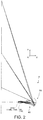
- the projection optical system 40 of the embodiment will be specifically described with reference to Fig. 2 and Fig. 3 .
- the projection optical system 40 illustrated in Fig. 2 or the like has the same configuration as the projection optical system 40 of Example 1 to be described below.
- the projection optical system 40 of the embodiment projects an image formed on a projection-performed surface of the liquid crystal panel 18G (18R or 18B), onto a screen (not shown).
- a prism PR corresponding to the cross dichroic prism 19 in Fig. 1 is disposed between the projection optical system 40 and the liquid crystal panel 18G (18R or 18B).
- the projection optical system 40 includes a first optical group 40a which is formed of a plurality of lenses and has positive power and a second optical group 40b which is configured of one mirror MR with a reflective surface having a concave aspheric shape.
- the first optical group 40a is formed to have a 1-1st lens group 41 having positive power, on the reduction side, and a 1-2nd lens group 42 having weaker positive or negative power, compared to the power of the 1-1st lens group 41, on the enlargement side, with the widest air interval BD, as a boundary, of a space formed between included lenses of the 1-1st lens group 41 and 1-2nd lens group 42 respectively.
- the 1-1st lens group 41 has an aperture ST inside thereof and is formed to have a lens group E1 on a reduction side from the aperture ST and a lens group E2 on an enlargement side from the aperture ST.
- the 1-2nd lens group 42 has, in order from the reduction side, three moving lens groups of an F1 lens group (hereinafter, lens group F1), an F2 lens group (hereinafter, lens group F2), and an F3 lens group (hereinafter, lens group F3), each group moving individually in an optical axis direction when focusing is performed in response to the magnification change, and a fixed lens group H (enlargement-side fixed lens group) which is fixed when focusing is performed in response to the magnification change.
- the fixed lens group H is configured of two negative lenses L15 and L16 and the lens L16 disposed on the outermost enlargement side is an aspheric lens molded using a resin.
- the lens L15 disposed on the reduction side is a glass lens.
- the lens L14 disposed on the outermost enlargement side that is, at a position in the vicinity of the fixed lens group H (enlargement-side fixed lens group) is an aspheric lens molded using a resin.
- the 1-2nd lens group 42 is configured to have at least two aspheric resin lenses and at least one glass lens disposed between the two aspheric resin lenses.
- the three lens groups F1 to F3 (moving lens group) are caused to individually move by the actuator AC in a direction A1 along the optical axis OA when focusing is performed in response to magnification change.
- the lenses L14 and L16 as the two aspheric resin lenses of the 1-2nd lens group 42 have an interval therebetween, which is changed when focusing is performed in response to the magnification change.
- the actuator AC can cause the lens groups F1 to F3 to move in various modes by performing of the focusing during magnification change and, for example, the three groups may completely individually move, but may be linked to each other using a cam mechanism or the like.
- the lens group E1 of the 1-1st lens group 41 has eight lenses L1 to L8 and the lens group E2 has two lenses L9 and L10.
- the lens group F1 as the moving lens group of the 1-2nd lens group 42 has one lens L11
- the lens group F2 has one lens L12
- the lens group F3 has two lenses L13 and L14
- the fixed lens group H positioned on the outermost enlargement side has two lenses L15 and L16 described above.
- the first optical group 40a is configured to have 16 lenses L1 to L16 as a whole.
- the lens L3 as a positive lens and the lens L4 as a negative lens form a cemented lens and the lens L7 and the lens L8 form a cemented lens.
- the lens L6 is a negative glass lens with both surfaces of aspheric shapes and is a negative aspheric meniscus lens with a concave aspheric shape on the enlargement side.
- the 1-1st lens group 41 has at least two sets of cemented lenses of the positive lenses and the negative lenses on the reduction side from the aperture ST and has at least one surface of the concave aspheric surface facing the enlargement side.
- the lenses other than the lens L6 are spherical glass lenses.
- the lenses L1 to L8 have a circular shape which is symmetric about the optical axis OA.
- the lenses L9 is a positive lens and the lens L10 is a negative lens.
- the lens L10 is a negative meniscus lens with the concave surface facing the enlargement side.
- the 1-1st lens group 41 is configured to have two lenses being a positive lens with the convex surface facing the enlargement side and a negative lens with the concave surface facing the enlargement side, in this order from the reduction side on the enlargement side from the aperture ST.
- lenses L9 and L10 are spherical glass lenses having a circular shape which is symmetric about the optical axis OA.
- the lens L11 configuring the lens group F1 is a positive biconvex lens. Further, the lens L11 is a spherical glass lens having a circular shape which is symmetric about the optical axis OA.
- the lens L12 configuring the lens group F2 is a positive biconvex lens. Further, the lens L12 is a spherical glass lens having a circular shape which is symmetric about the optical axis OA.
- the lens L13 is a negative meniscus lens.
- the lens L13 is a spherical glass lens having a circular shape which is symmetric about the optical axis OA.
- the lens L14 is an aspheric resin lens as described above. More specifically, the lens L14 is a lens (aspheric lens) which has negative power and has both surfaces subjected to an aspheric surface process, and is a lens (resin lens) molded using a resin. Further, the lens L14 has a circular shape which is symmetric about the optical axis OA.
- the lens L15 is a negative biconcave lens. Further, the lens L15 is a spherical glass lens having a circular shape which is symmetric about the optical axis OA.
- the lens L16 is a lens (aspheric lens) which has negative power with both surfaces subjected to an aspheric surface process, and is a lens (resin lens) molded using a resin.
- the lens L16 is not formed to have a circular shape, but to have a partially notched shape which is notched on the upper side (side on which image light is projected) from a state of a circular shape which is symmetric about the optical axis OA.
- the second optical group 40b is configured of one mirror MR having a concave aspheric shape and the mirror MR reflects the image light emitted from the first optical group 40a, and thereby projects the image light to a screen.
- lenses L1 to L15 have a circular shape which is symmetric about the optical axis OA and lens L16 has a partially notched shape from a circular shape which is symmetric about the optical axis OA.
- the mirror MR configuring the second optical group 40b also has a partially notched shape from a circular shape which is symmetric about the optical axis OA.
- elements configuring the first optical group 40a and the second optical group 40b all belong to a rotationally symmetric system.
- the reduction side in the projection optical system 40 is substantially telecentric. For example, as described above, in a case where light fluxes modulated by the respective liquid crystal panels 18R, 18G, and 18B in the cross dichroic prism 19 are combined into image light, it is possible to hereby easily absorb variations due to assembly.
- a short throw projection optical system including the projection optical system 40 as above has an abnormally short distance to a screen.
- an object positioned on a panel surface PI of the liquid crystal panel 18G (18R or 18B) (that is, an image on a panel) in the first optical group 40a is temporarily formed as an image in front of a mirror of the second optical group 40b, is again formed as an image on a screen by one mirror MR configuring the second optical group 40b, and thereby short throw projection is performed in the first optical group 40a.
- the first optical group 40a plays a role of forming a primary image (intermediate image) in front of the mirror MR.
- the 1-2nd lens group 42 of the first optical group 40a has the aspheric resin lens in addition to the one disposed on the outermost enlargement side, for example.
- the 1-2nd lens group 42 includes at least two aspheric lens molded using the resin.
- at least one glass lens is disposed between the plurality of resin lenses.
- the lens L15 as the spherical glass lens is disposed between the lens L14 and the lens L16 as aspheric resin lenses.
- the angle of the light flux incident to the resin lens L16 from the glass lens L15 is hereby controlled, the resin lenses L14 and L16 have weak power, and thus it is possible to prevent variations in the shapes of the resin lens L16.
- a plurality of resin lenses are provided, and thereby it is possible to hereby perform effective correction in order to suppress aberration fluctuation to be decreased.
- the second optical group 40b is configured of one mirror MR, it is possible to hereby achieve a good image having small aberration, compared to an image of which the primary image has moderate aberration, and which is finally projected on the screen through the second optical group 40b.
- the projector 2 as a short throw projector, a wide range of magnification change is covered and it is possible to be also applied to an image display element having high resolution.
- the fixed lens group H as the fixed group is disposed on the enlargement side
- the moving lens group which moves when focusing is performed in response to the magnification change, is disposed on the reduction side from the fixed lens group H, and thereby it is possible to perform effective correction in order to suppress the aberration fluctuation to be reduced.
- the first optical group 40a when one aspheric lens is included in the lenses configuring the 1-2nd lens group 42 as a focusing group disposed on the enlargement side, there is a concern that a sufficient range of magnification change will not be secured by a design.
- the shapes of the respective aspheric lenses have a strong tendency to be changed into severe aspheric shapes by separating large surface shape from the spherical shape in order to obtain sufficiently wide range of magnification change, surface sensitivity or refractive index sensitivity is enhanced, further, eccentricity sensitivity between the surfaces is enhanced, and then it is possible for significant variation in the final lens performance to occur.
- the lens disposed on the outermost enlargement side such as the aspheric lens (lens L16) of the 1-2nd lens group 42
- the lens L16 in order to prevent interference with a light flux reflected from the mirror of the second optical group 40b, not only there is a need to have an atypical shape such as a partially notched circular shape, but also, an aspheric resin-molded surface is normally used because the diameter is relatively great such that, in the present embodiment, the lens L16 is also an aspheric resin lens having an atypical shape.
- the aspheric resin-molded surface also has lower accuracy than the aspheric glass-molded surface, and thus there is a need to sufficiently reduce sensitivity at the time of design because the system is likely to be influenced by variations due to surface accuracy or refractive index as described above.
- the 1-2nd lens group 42 as the focusing group includes two aspheric lenses (lens L14, L16), a negative glass lens (lens L15) is disposed therebetween.
- the negative power of the aspheric lens is appropriately distributed, it is possible to reduce relative sensitivity between the aspheric surface, and it is possible to reduce the aberration fluctuation even in a wide range of the magnification change.
- the 1-2nd lens group 42 as the focusing group it is also possible to dispose a fixed lens group on the reduction side.
- the number of moving lens groups of the focusing groups can be decreased (in Example 2 to be described below, instead of three moving lens groups, configured of two moving lens groups), a frame structure or the like which fixes the lenses is simplified, and it is possible to obtain the entire apparatus at a low cost.
- the aspheric glass surface (lens L6) is appropriately disposed on the reduction side from the aperture ST, and thereby it is possible to achieve an image having less flare and high contrast even at the F-number of about 1.6.
- the numerical aperture on the object side is equal to or more than 0.3, that is, with brightness having the F-number of about 1.6, a range of magnification change of high magnification of 1.5 (further, equal to or more than 1.6) is secured, and performance of sufficient application to the image display element having high resolution is achieved.
- the aspheric surface is defined by the following polynomial equation (aspheric surface equation).
- z c h 2 1 + 1 ⁇ k + 1 c 2 h 2 + A 4 h 4 + A 6 h 6 + A 8 h 8 + A 10 h 10 + A 12 h 12 + A 14 h 14
- polynomial equation c h 2 1 + 1 ⁇ k + 1 c 2 h 2 + A 4 h 4 + A 6 h 6 + A 8 h 8 + A 10 h 10 + A 12 h 12 + A 14 h 14
- Table 1 Data of lens surfaces of Example 1 is shown in Table 1. Further, OBJ means the panel surface PI and STO means the aperture ST. In addition, a surface having "*" after a surface reference number means a surface having aspheric shape.
- Table 1 f 4.150 ⁇ 72.9 NA 0.313 R D Nd Vd OBJ Infinity 9.400 1 Infinity 27.908 1.51633 64.14 2 Infinity 0.000 3 40.014 7.200 1.49700 81.54 4 -255.649 0.200 5 36.347 7.800 1.49700 81.54 6 -152.931 0.200 7 29.838 9.200 1.48749 70.24 8 -37.003 1.200 1.90366 31.31 9 26.317 0.100 10 16.951 7.500 1.48749 70.24 11 -838.804 0.100 *12 113.564 1.600 1.74320 49.29 *13 30.000 0.100 14 18.311 8.000 1.53172 48.84 15 -16.680 1.200 1.79952 42.22 16 34.631 4.000
- Table 2 shows an aspheric surface coefficient of a lens surface of Example 1.
- Table 2 Aspheric Surface Coefficient K A04 A06 A08 A10 A12 A14 12 41.7552 -2.7588E-05 4.4936E-07 -2.7734E-09 1.1565E-11 -2.0673E-14 0.0000E+00 13 4.8011 -1.1587E-05 4.5419E-07 -3.0749E-09 1.2463E-11 -2.7707E-14 0.0000E+00 28 0.0000 -1.7926E-05 2.4112E-08 -8.4914E-12 -2.1642E-15 0.0000E+00 0.0000E+00 29 0.0000 -2.1140E-05 2.3908E-08 -9.6403E-12 0.0000E+00 0.0000E+00 0.0000E+00 32 3.2860 2.8102E-06 4.2059E-09 4.2001E-12 -1.3317E-14 7.4306E-18 0.0000E+
- Table 3 shows values of variable intervals 21, 23, 25, 29, and 34 in Table 2 at the projection magnification of 135 times, the projection magnification of 106 times, and the projection magnification of 179 times.
- Table 3 Variable Interval 135x 106x 179x 21 23.996 24.133 23.834 23 2.753 1.500 3.999 25 6.845 6.831 6.866 29 12.105 13.234 11.000 34 -600.000 -477.350 -783.927
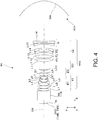
- Fig. 4 is a sectional diagram showing the projection optical system of Example 1.
- the projection optical system in Fig. 4 corresponds to the projection optical system 40 of Embodiment 1.
- the lens L16 or the mirror MR having a partially notched shape from a circle in Fig. 3 or the like is depicted intact without a notch in Fig. 4 .
- the projection optical system performs enlargement projection of an image on the panel surface PI to the screen at a magnification depending on a distance.
- the projection optical system has 16 lenses L1 to L16 of the lenses L1 to L8 configuring the lens group E1 of the 1-1st lens group 41, the lenses L9 and L10 configuring the lens group E2 thereof, the lens L11 configuring lens group F1 of the 1-2nd lens group 42, the lens L12 configuring the lens group F2 thereof, the lenses L13 and L14 configuring the lens group F3 thereof, and the lenses L15 and L16 configuring the fixed lens group H, in this order from the reduction side.
- the magnification change occurs due to the change of a projection position (change of projection distance), and the lens group H configuring the 1-1st lens group 41 and the 1-2nd lens group 42 are fixed as is when focusing is performed during the magnification change, whereas the lens groups F1 to F3 configuring the 1-2nd lens group 42 individually move.
- the interval between the lenses L14 and L16 as the two aspheric resin lens of the 1-2nd lens group 42 is hereby changed when focusing is performed in response to the magnification change.
- the lens L1 as a first lens is a positive lens
- the lens L2 as a second lens is a positive lens
- the lens L3 as a third lens is a positive lens
- the lens L4 as a fourth lens is a negative lens
- the lens L3 and the lens L4 form a cemented lens
- the lens L5 as a fifth lens is a positive lens
- the lens L6 as a sixth lens is a negative meniscus lens having both surfaces subjected to the aspheric surface process with a concave surface facing the enlargement side
- the lens L7 as a seventh lens is a positive biconvex lens
- the lens L8 as an eighth lens is a negative biconcave lens
- the lens L7 and the lens L8 form a cemented lens
- the lens L9 as a ninth lens is a positive biconvex lens
- the lens L10 as the tenth lens is a negative meniscus lens with the conca
- the lens L11 as an eleventh lens is a positive lens
- the lens L12 as a twelfth lens is a positive lens
- the lens L13 as a thirteenth lens is a negative lens
- the lens L14 as a fourteenth lens is a negative lens having both surfaces subjected to the aspheric surface process
- the lens L15 as a fifteenth lens is a negative lens
- the lens L16 as a sixteenth lens is a negative lens having both surfaces subjected to the aspheric surface process.
- the second optical group 40b is configured of one mirror having a concave aspheric surface.
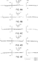
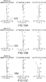
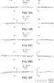
- Fig. 5A is a diagram showing aberration (spherical aberration, astigmatism, and distortion) on the reduction side of the projection optical system when the projection magnification of 135 times is performed.
- Fig. 5B is a diagram showing aberration on the reduction side of the projection optical system when the projection magnification of 106 times is performed.
- Fig. 5C is a diagram showing aberration on the reduction side of the projection optical system when the projection magnification of 179 times is performed.
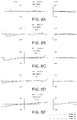
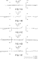
- Figs. 6A to 6E are diagrams showing lateral aberration of the projection optical system, which correspond to Fig. 5A .
- Fig. 6A is a diagram showing the lateral aberration in a case of the maximum angle of view and Figs.
- FIGS. 6A to 6E are diagrams showing lateral aberration at five angles of view.
- Figs. 7A to 7E are diagrams showing lateral aberration of the projection optical system, which correspond to Fig. 5B .
- Figs. 8A to 8E are diagrams showing lateral aberration of the projection optical system, which correspond to Fig. 5C .
- OBJ means the panel surface PI
- STO means the aperture ST.
- a surface having "*" after a surface reference number means a surface having aspheric shape.
- Table 4 f 4.171 ⁇ 72.9 NA 0.313 R D Nd Vd OBJ Infinity 9.400 1 Infinity 27.908 1.51633 64.14 2 Infinity 0.000 3 35.294 9.800 1.49700 81.54 4 -85.567 0.200 5 33.124 7.200 1.49700 81.54 6 -301.905 0.200 7 64.998 8.000 1.51633 64.14 8 -27.374 1.200 1.90366 31.31 9 61.009 0.200 10 21.894 6.700 1.51633 64.14 11 -30.792 1.600 1.83220 40.10 *12 48.420 1.000 13 26.724 6.400 1.54814 45.78 14 -26.724 0.615 15 -59.344 1.200 1.78590 44.20 16 29.247 5.419 STO
- Table 5 shows an aspheric surface coefficient of a lens surface of Example 2.
- Table 5 Aspheric Surface Coefficient K A04 A06 A08 A10 A12 A14 12 10.7205 2.2599E-05 -3.6917E-08 5.2139E-11 -1.5830E-12 0.0000E+00 0.0000E+00 27 0.0000 -3.0294E-05 2.4795E-08 3.5116E-12 -5.4910E-15 0.0000E+00 0.0000E+00 28 0.0000 -3.4688E-05 3.3814E-08 -1.4840E-11 5.8670E-15 0.0000E+00 0.0000E+00 31 3.2860 9.4048E-06 1.0286E-08 -2.0983E-11 1.5102E-14 -3.9051E-18 0.0000E+00 32 -1.0000 -4.2315E-06 1.2030E-08 -7.5394E-12 -5.8590E-15 9.2843E-18 -3.4672E-21 33
- Table 6 shows values of variable intervals 23, 26, 30, and 33 in Table 5 at the projection magnification of 134 times, the projection magnification of 105 times, and the projection magnification of 178 times.
- Table 6 Variable interval 134x 105x 178x 23 6.678 4.000 9.332 26 8.961 10.793 7.163 30 3.403 4.248 2.546 33 -600.000 -478.094 -782.728
- Fig. 9 is a sectional diagram showing the projection optical system of Example 2. Further, the lens L16 and the mirror MR having a partially notched shape from a circle in an actual optical system are depicted intact without a notch in Fig. 9 .
- the projection optical system performs enlargement projection of an image on the panel surface PI to the screen at a magnification depending on a distance.
- the projection optical system has 16 lenses L1 to L16 of the lenses L1 to L8 configuring the lens group E1 of the 1-1st lens group 41, the lenses L9 and L10 configuring the lens group E2 thereof, the lens L11 configuring a first fixed lens group H1 of the 1-2nd lens group 42, the lenses L12 and L13 configuring the lens group F1 thereof, the lenses L14 and L15 configuring the lens group F2 thereof, and the lens L16 configuring a second fixed lens group H2, in this order from the reduction side.
- the magnification change occurs due to the change of a projection position (change of projection distance), and the first and second fixed lens groups H1 and H2 configuring the 1-2nd lens group 42 and the 1-1st lens group 41 are fixed as is when focusing is performed during the magnification change, whereas the lens groups F1 and F2 configuring the 1-2nd lens group 42 individually move.
- the interval between the lenses L14 and L16 as the two aspheric resin lenses of the 1-2nd lens group 42 is hereby changed when focusing is performed in response to the magnification change.
- the first optical group 40a is configured to have 16 lenses from the lens L1 (first lens) to the lens L16 (sixteenth lens) numbered from the reduction side, and the first optical group 40a can be divided into the 1-1st lens group 41 having positive power, on the reduction side, and the 1-2nd lens group 42 having weaker positive or negative power, compared to the power of the 1-1st lens group 41, on the enlargement side, with the widest air interval BD as a boundary.
- the 1-1st lens group 41 is configured to include the lens group E1 having the positive lens L1, the positive lens L2, the cemented lens of the positive lens L3 and the negative lens L4, the cemented lens of the positive lens L5 and the negative lens L6 subjected to the aspheric surface process with the concave surface facing the enlargement side, the positive lens L7, and the negative lens L8, the aperture ST, and the lens group E2 having the positive biconvex lens L9, and the negative meniscus lens L10 with the concave surface facing the enlargement side, in this order from the reduction side.
- a total of ten lenses in lens groups E1 and E2 are sequentially arranged.
- the 1-2nd lens group 42 is configured to include the first fixed lens group H1 having the positive lens L11, the lens group F1 (F1 lens group) having the cemented lens of the positive lens L12 and the negative lens L13, the lens group F2 (F2 lens group) having the negative lens L14 having both surfaces subjected to the aspheric surface process and the negative lens L15, and the second fixed lens group H2 having the negative lens L16 having both surfaces subjected to an aspheric surface process, in this order from the reduction side.
- a total of six lenses in the fixed lens groups H1 and H2 and the lens group F1 and F2 are sequentially disposed.
- the lens L14 and the lens L16 are lenses molded using a resin and the lens L15 disposed between the lens L14 and the lens L16 is the glass lens.
- the 1-2nd lens group 42 performs focusing by causing the two lens groups F1 and F2 to individually move, when the projection distance is changed during the magnification change.
- the second optical group 40b is configured of one mirror having a concave aspheric surface.
- Fig. 10A is a diagram showing aberration (spherical aberration, astigmatism, and distortion) on the reduction side of the projection optical system when the projection magnification of 134 times is performed.
- Fig. 10B is a diagram showing aberration on the reduction side of the projection optical system when the projection magnification of 105 times is performed.
- Fig. 10C is a diagram showing aberration on the reduction side of the projection optical system when the projection magnification of 178 times is performed.
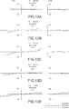
- Figs. 11A to 11E are diagrams showing lateral aberration of the projection optical system, which correspond to Fig. 10A .
- Fig. 11A is a diagram showing the lateral aberration in a case of the maximum angle of view and Figs.
- FIGS. 11A to 11E are diagrams showing lateral aberration at five angles of view.
- Figs. 12A to 12E are diagrams showing lateral aberration of the projection optical system, which correspond to Fig. 10B .
- Figs. 13A to 13E are diagrams showing lateral aberration of the projection optical system, which correspond to Fig. 10C .
- OBJ means the panel surface PI and STO means the aperture ST.
- a surface having "*" after a surface reference number means a surface having aspheric shape.
- Table 7 f 4.170 ⁇ 73.0 NA 0.313 R D Nd Vd OBJ Infinity 9.400 1 Infinity 27.908 1.51633 64.14 2 Infinity 0.000 3 32.799 9.800 1.49700 81.54 4 -125.875 0.200 5 33.199 7.200 1.49700 81.54 6 -279.426 0.200 7 64.435 8.000 1.51633 64.14 8 -28.940 1.200 1.90366 31.31 9 73.268 0.200 10 21.610 6.700 1.51633 64.14 11 -26.005 1.600 1.83220 40.10 *12 48.530 1.000 13 26.267 6.400 1.54814 45.78 14 -26.267 0.100 15 -54.604 1.200 1.78590 44.20 16 29.080
- Table 8 shows an aspheric surface coefficient of a lens surface of Example 3.
- Table 8 Aspheric Surface Coefficient K A04 A06 A08 A10 A12 A14 12 10.8601 2.3660E-05 -4.2016E-08 4.0629E-11 -1.5830E-12 0.0000E+00 0.0000E+00 28 0.0000 -2.8133E-05 2.8535E-08 -1.4118E-12 -5.4910E-15 0.0000E+00 0.0000E+00 29 0.0000 -3.3294E-05 3.8307E-08 -1.9340E-11 5.8670E-15 0.0000E+00 0.0000E+00 32 3.2860 9.2013E-06 1.2095E-08 -2.1197E-11 1.4603E-14 -4.0310E-18 0.0000E+00 33 -1.0000 -1.7505E-06 8.4160E-09 -3.3971E-12 -5.7594E-15 6.8674E-18 -2.7020E-21 34 -1.0000
- Table 9 shows values of variable intervals 23, 27, 29, 33, and 34 in Table 8 at the projection magnification of 135 times, the projection magnification of 105 times, and the projection magnification of 222 times.
- Table 9 Variable Interval 135x 105x 222x 23 2.148 0.541 4.637 27 10.547 11.204 9.495 29 4.445 5.114 3.500 33 113.625 113.905 113.133 34 -600.000 -476.336 -969.054
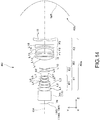
- Fig. 14 is a sectional diagram showing the projection optical system of Example 3. Further, the lens L16 and the mirror MR having a partially notched shape from a circle in an actual optical system are depicted intact without a notch in Fig. 14 .
- the projection optical system performs enlargement projection of an image on the panel surface PI to the screen at a magnification depending on a distance.
- the projection optical system has 16 lenses L1 to L16 of the lenses L1 to L8 configuring the lens group E1 of the 1-1st lens group 41, the lenses L9 and L10 configuring the lens group E2 thereof, the lens L11 configuring the fixed lens group H of the 1-2nd lens group 42, the lenses L12 and L13 configuring the lens group F1 thereof, the lens L14 configuring the lens group F2 thereof, and the lenses L15 and L16 configuring the lens group F3, in this order from the reduction side.
- the fixed lens group does not exist on the enlargement side.
- the magnification change occurs due to the change of a projection position (change of projection distance), and the 1-1st lens group 41 and the fixed lens group H configuring the 1-2nd lens group 42 are fixed as is when focusing is performed during the magnification change, whereas the lens groups F1 to F3 configuring the 1-2nd lens group 42 each move, respectively.
- the movement causes the interval between the lenses L14 and L16 as the two aspheric resin lens of the 1-2nd lens group 42 to be changed when focusing is performed in response to the magnification change.
- the first optical group 40a is configured to have 16 lenses from the lens L1 (first lens) to the lens L16 (sixteenth lens) numbered from the reduction side, and the first optical group 40a can be divided into the 1-1st lens group 41 having positive power, on the reduction side, and the 1-2nd lens group 42 having weaker positive or negative power, compared to the power of the 1-1st lens group 41, on the enlargement side, with the widest air interval BD as a boundary between the lens groups 41 and 42.
- the 1-1st lens group 41 is configured to include the lens group E1 having the positive lens L1, the positive lens L2, the cemented lens of the positive lens L3 and the negative lens L4, the cemented lens of the positive lens L5 and the negative lens L6 subjected to the aspheric surface process with the concave surface facing the enlargement side, the positive biconvex lens L7, and the negative biconcave lens L8, the aperture ST, and the lens group E2 having the positive biconvex lens L9, and the negative meniscus lens L10 with the concave surface facing the enlargement side, in this order from the reduction side.
- a total of ten lenses in lens groups E1 and E2 are sequentially arranged.
- the 1-2nd lens group 42 is configured to include the fixed lens group H having the positive lens L11, the lens group F1 (F1 lens group) having the positive lens L12 and the negative lens L13, the lens group F2 (F2 lens group) having the negative lens L14 having both surfaces subjected to the aspheric surface process, and the lens group F3 (F3 lens group) having the negative lens L15 and the negative lens L16 having both surfaces subjected to an aspheric surface process, in this order from the reduction side.
- a total of six lenses in the fixed lens groups H and the lens groups F1 to F3 are sequentially disposed.
- the lens L14 and the lens L16 are lenses molded using a resin and the lens L15 disposed between the lens L14 and the lens L16 is the glass lens.
- the 1-2nd lens group 42 performs focusing by causing the three lens groups F1, F2, and F3 to move individually for the focus when focusing is performed in response to the magnification change.
- the second optical group 40b is configured of one mirror having a concave aspheric surface.
- Fig. 15A is a diagram showing aberration (spherical aberration, astigmatism, and distortion) on the reduction side of the projection optical system when the projection magnification of 135 times is performed.
- Fig. 15B is a diagram showing aberration on the reduction side of the projection optical system when the projection magnification of 105 times is performed.
- Fig. 15C is a diagram showing aberration on the reduction side of the projection optical system when the projection magnification of 222 times is performed.
- Figs. 16A to 16E are diagrams showing lateral aberration of the projection optical system, which correspond to Fig. 15A .
- Fig. 16A is a diagram showing the lateral aberration in a case of the maximum angle of view and Figs.
- FIGS. 16A to 16E are diagrams showing lateral aberration at five angles of view.
- Figs. 17A to 17E are diagrams showing lateral aberration of the projection optical system, which correspond to Fig. 15B .
- Figs. 18A to 18E are diagrams showing lateral aberration of the projection optical system, which correspond to Fig. 15C .
- a simple configuration in which the lens on the outermost enlargement side is one aspheric resin lens, is employed while a wide angle of view is equal to or greater than a half angle of view of 70° at a wide angle end.
- one or more lenses having substantially no power may be added before and after or between the lenses configuring each lens group.
- a target of enlargement projection by the projection optical system 40 is not limited to the liquid crystal panels 18G, 18R, and 18B, but it is possible for the projection optical system 40 to perform enlargement projection of an image formed by various light flux modulating elements such as a digital micro mirror device, in which a micro mirror functions as a pixel.
Landscapes
- Physics & Mathematics (AREA)
- General Physics & Mathematics (AREA)
- Optics & Photonics (AREA)
- Lenses (AREA)
- Microscoopes, Condenser (AREA)
- Projection Apparatus (AREA)
Abstract
Description
- The present invention relates to a projection optical system suitable for being incorporated in a projector which performs enlargement projection of an image of an image display element.
- A refraction optical system configured to include a plurality of lenses as a projection optical system for a projector which can perform projection from a short distance and can obtain a large picture plane by having a wide angle of view substantially equal to a half angle of view of 60 degrees, is proposed (see
JP-A-2007-147970 - As a method to solve the drawbacks of the refraction optical system, a refraction optical system formed of a plurality of lenses and a refraction/reflection complex optical system which uses at least one curved reflective mirror have been proposed (for example, see
JP-A-2006-235516 JP-A-2007-079524 - However, for example, in
JP-A-2006-235516 JP-A-2007-079524 JP-A-2006-235516 - As above, in the refraction/reflection complex optical system, an ultra-wide angle of view is obtained but it is difficult to decrease the entire length, and thereby there are drawbacks in that the mirror is increased in size. The system is suitable for the usage in which the optical system is bent and disposed in a large housing such as one in a rear projector. However, the system is not suitable for equipment such as a front projector in which portability is important.
- In comparison, a system in which a reflective mirror is used as a front projector has been known (
JP-A-2008-250296 JP-A-2012-203139 JP-A-2008-250296 JP-A-2012-203139 - Incidentally, in the related art, a projector for the short throw application is usually used by being fixed during installment such as ceiling installment or wall installment, with respect to a fixed screen. However, recently, there is a high demand that not only the projector is disposed upright, and performs projection onto a table surface with a relatively small projection size, but also the projector moves to a relatively large room and can be applied to a large picture plane projection. In a case of the large picture plane projection, in order to obtain sufficient contrast even in a relatively bright place, there is a need to use a bright optical system even to a small extent.
- An advantage of some aspects of the invention is to provide a projection optical system which can cover a wide range of magnification change in an application to a short throw projector and can be applied to an image display element having high resolution.
- A projection optical system according to an aspect of the invention includes: in order from a reduction side, a first optical group which is formed of a plurality of lenses and has positive power; and a second optical group which has one reflective surface having a concave aspheric shape. The first optical group is formed to have a 1-1st lens group having positive power, on the reduction side, and a 1-2nd lens group having weaker positive or negative power, compared to the power of the 1-1st lens group, on the enlargement side, with the widest air interval as a boundary. The 1-2nd lens group includes at least two aspheric resin lenses and at least one glass lens disposed between the two aspheric resin lenses. Here, in comparison between power of the lenses and the lens groups, the relatively weak power means a lower value in a case where absolute values of power are compared. In other words, for the power of the 1-2nd lens group, the above description means that the absolute value thereof is less than an absolute value of the power of the 1-1st lens group.
- First, in this case of the configuration described above, the first optical group plays a role of causing an image of an object (that is, a panel section) to be formed as an image in front of a mirror of the second optical group and forming a primary image in orderto form an image again on a screen by the mirror of the second optical group. At this time, since the second optical group is configured only of one mirror, it is difficult to individually correct aberration. Accordingly, in order to obtain a final image having small aberration on the screen by the second optical group, there is a need to form the primary image containing aberration in the first optical group.
- Further, in the ultra-wide angle projection optical system having the configuration described above, when the projection magnification is changed, the aberration fluctuation is likely to increase because an angle of view is abnormally wide. Accordingly, the first optical group needs to form the primary image which contains aberration corresponding to the change of image forming magnification even when the image forming magnification is changed.
- In comparison, in the projection optical system according to the aspect of the invention, as described above, the 1-2nd lens group includes at least two aspheric resin lenses, and thereby it is possible to form a primary image needed to obtain a good image on a screen. In application to a short throw projector, a wide range of magnification change is covered and it is possible to be also applied to an image display element having high resolution.
- Particularly, in order to obtain an image having high contrast with respect to a high-definition panel and having low distortion, a plurality of focusing lens groups configuring the 1-2nd lens group and a mirror configuring the second optical group need to be appropriately disposed, and, especially, it is preferable that the 1-2nd lens group includes at least two aspheric lenses molded using a resin.
- Here, a plurality of aspheric lenses are used, and thereby high definition and low distortion are relatively easily achieved. However, in a case of using the plurality of aspheric surfaces, in general, high surface accuracy of the respective aspheric surfaces is needed, and eccentricity between the aspheric surfaces of the respective lenses is likely to result in the performance deterioration. Further, as the general characteristics of the resin-molded lens, since the shrinkage factor of the material is great, it is difficult to secure accuracy of the surface, compared to the glass-molded lens or the like. In addition, when the power becomes excessively strong, an uneven thickness ratio representing a ratio of the lens thickness in the vicinity of the optical axis and the lens thickness at the outer circumferential portion is increased, and thus it is known that internal distortion occurs in a gate portion which is formed during molding or in an outer circumferential portion, which influences on the performance. A linear expansion coefficient, a refractive index, or a temperature coefficient of the resin is increased by one digit, compared to the case of the glass lens, which results in a focal position shift due to a focal distance change according to a surrounding temperature or a temperature change during an operation. Accordingly, for the resin lens, it is not preferable that a single body has strong power. For this reason, it is preferable that the resin lens has weak power to the smallest extent, and has a low uneven thickness ratio.
- In comparison, in the aspect of the invention, at least one glass lens is disposed between a plurality of resin lenses, and thereby the power of the resin lens is lowered. An angle of the light flux incident to the resin lens is controlled by the glass lens. In this manner, the optimal incident angle to the resin lens is obtained, and thereby it is possible to prevent performance deterioration due to variations of shapes or internal distortion.
- In a specific aspect of the invention, an interval between the two aspheric resin lenses of the 1-2nd lens group is changed when focusing is performed in response to the magnification change. In this case, the interval between the aspheric lenses is changed, and thereby it is possible to achieve high definition and low distortion of the image over the wide range of the magnification change.
- In a case where the plurality of aspheric lenses are arranged in parallel, sensitivity to the interval of the lenses or sensitivity to eccentricity between the lenses is excessively increased and excessively high accuracy such as frame accuracy of the moving group is needed. In comparison, in the above aspect, the glass lens (spherical lens) is disposed between the aspheric lenses, and thereby it is possible to decrease the sensitivity between the aspheric lenses. Further, the aspheric lenses move as the moving group, and as a result, it is possible to achieve high definition and low distortion.
- Further, for the resin-molded lens, a lens having a large aperture can be relatively low in cost, and it is advantageous that the resin-molded lens can be applied to a lens having a shape other than the circular shape, relatively simply.
- In another aspect of the invention, the 1-1st lens group is configured to have an aperture therein and two lenses of a positive lens with a convex surface facing the enlargement side and a negative lens with the concave surface facing the enlargement side, in this order from the reduction side, on the enlargement side from the aperture. In this case, the two lenses as described above are disposed on the enlargement side from the aperture, and thereby it is possible to maintain good performance even in a wide range of the magnification change.
- The 1-1st lens group plays a role of efficiently receiving the light flux from the object (that is, the panel) side and sending the light flux to the 1-2nd lens group as the focusing lens group. The 1-2nd lens group, as the focusing lens group, needs to play a role of forming an appropriate intermediate image even in a wide range of the magnification change. As described above, the lens group disposed on the enlargement side from the aperture of the 1-1st lens group is two lenses, one positive and one negative, particularly, the positive lens with the convex surface facing the enlargement side and the negative lens with the concave surface facing the enlargement side are disposed in this order from the reduction side, and thereby it is possible to define the surface of the 1-1st lens group on the outermost enlargement side as an emission surface. The 1-1st lens group and the 1-2nd lens group as the focusing lens group are hereby combined, then, it is possible to correct the field curvature and astigmatism characteristics in the wide range of the magnification change and it is possible to obtain stable performance in order to form an appropriate intermediate image.
- In still another aspect of the invention, the 1-1st lens group has an aperture therein, includes at least two sets of cemented lenses, each of a positive lens and a negative lens, disposed on the reduction side from the aperture, and has at least one concave aspheric surface facing the enlargement side. In this case, an occurrence of chromatic aberration is prevented even in a configuration in which a small number of lenses are used, assembly variations is decreased, and it is possible to increase numerical aperture (brighten).
- The plurality of lenses disposed on the reduction side from the aperture of the 1-1st lens group play a role of efficiently receiving the light flux from the object (that is, the panel) side. In a case where the plurality of lenses are configured of only the spherical lenses, there is a possibility that the number of lenses needs to be increased. When the number of lenses is increased, transmittance is reduced, the entire length of the lens is increased due to the increase of the lenses, and the configurational number of lenses needs to be set to the minimum extent.
- For example, in order to cover the brightness having F-number of about 1.6, at least surface having the concave aspheric shape on the enlargement side is included on the reduction side from the aperture of the 1-1st lens group, thereby the brightness is secured, an occurrence of flare is suppressed, and it is possible to provide an image having high contrast. In addition, at least two sets of cemented lenses are configured to be disposed on the reduction side from the aperture of the 1-1st lens group, thereby an occurrence of chromatic aberration is suppressed to the smallest extent, and assembling properties are enhanced by cementing.
- In still another aspect of the invention, the numerical aperture on the object side is equal to or more than 0.3. In this case, it is possible to form a sufficiently bright projection image.
- In still another aspect of the invention, the reduction side is substantially telecentric.
- In still another aspect of the invention, elements configuring the first optical group and the second optical group all have a rotationally symmetric system.
- In still another aspect of the invention, a range of magnification change is equal to or greater than 1.5 times.
- Embodiments of the invention will now be described by way of example only with reference to the accompanying drawings, wherein like numbers reference like elements.
-
Fig. 1 is a diagram showing a schematic configuration of a projector in which a projection optical system of an embodiment is incorporated. -
Fig. 2 is a diagram showing light fluxes and a configuration from an object surface to a projection surface in the projection optical system of the embodiment or Example 1. -
Fig. 3 is an enlarged diagram showing a part from the object surface to a concave reflective mirror inFig. 2 . -
Fig. 4 is a diagram showing a configuration of the projection optical system of Example 1. -
Figs. 5A to 5C are diagrams showing aberration on a reduction side of the projection optical system of Example 1. -
Figs. 6A to 6E are diagrams showing lateral aberration of the projection optical system, which correspond toFig. 5A . -
Figs. 7A to 7E are diagrams showing lateral aberration of the projection optical system, which correspond toFig. 5B . -
Figs. 8A to 8E are diagrams showing lateral aberration of the projection optical system, which correspond toFig. 5C . -
Fig. 9 is a diagram showing a configuration of a projection optical system of Example 2. -
Figs. 10A to 10C are diagrams showing aberration on a reduction side of the projection optical system of Example 2. -
Figs. 11A to 11E are diagrams showing lateral aberration of the projection optical system, which correspond toFig. 10A . -
Figs. 12A to 12E are diagrams showing lateral aberration of the projection optical system, which correspond toFig. 10B . -
Figs. 13A to 13E are diagrams showing lateral aberration of the projection optical system, which correspond toFig. 10C . -
Fig. 14 is a diagram showing a configuration of a projection optical system of Example 3. -
Figs. 15A to 15C are diagrams showing aberration on a reduction side of the projection optical system of Example 3. -
Figs. 16A to 16E are diagrams showing lateral aberration of the projection optical system, which correspond toFig. 15A . -
Figs. 17A to 17E are diagrams showing lateral aberration of the projection optical system, which correspond toFig. 15B . -
Figs. 18A to 18E are diagrams showing lateral aberration of the projection optical system, which correspond toFig. 15C . - Hereinafter, a projection optical system according to an embodiment of the invention will be described in detail with reference to the drawings.
- As illustrated in
Fig. 1 , aprojector 2, in which the projection optical system according to an embodiment of the invention is incorporated, includes anoptical system section 50 which projects image light, and acircuit device 80 which controls an operation of theoptical system section 50. - In the
optical system section 50, alight source 10 is, for example, an extra-high pressure mercury lamp, and emits light fluxes including an R light flux, a G light flux, and a B light flux. Thelight source 10 may be a discharge light source, in addition to an extra-high pressure mercury lamp, or may be a solid-state light source, such as an LED or a laser. Afirst integrator lens 11 and asecond integrator lens 12 have a plurality of lens elements arranged in an array. Thefirst integrator lens 11 divides a light flux from thelight source 10 into a plurality of light fluxes. Each lens element of thefirst integrator lens 11 condenses the light flux from thelight source 10 in the vicinity of the lens elements of thesecond integrator lens 12. The lens elements of thesecond integrator lens 12 form images of the lens elements of thefirst integrator lens 11 on theliquid crystal panels lens 14. In this configuration, the entire display regions of theliquid crystal panels light source 10, in substantially uniform brightness. - A
polarization conversion element 13 converts a light flux from thesecond integrator lens 12 to a predetermined linearly polarized light flux. The superimposinglens 14 superimposes the image of each lens element of thefirst integrator lens 11 on the display regions of theliquid crystal panels second integrator lens 12. - A first
dichroic mirror 15 reflects the R light flux incident from the superimposinglens 14 and transmits the G light flux and the B light flux. The R light flux reflected from the firstdichroic mirror 15 is incident to theliquid crystal panel 18R serving as an optical modulator through areflective mirror 16 and afield lens 17R. Theliquid crystal panel 18R modulates the R light flux in response to an image signal so as to form an R-color image. - A second
dichroic mirror 21 reflects the G light flux from the firstdichroic mirror 15 and transmits the B light flux. The G light flux reflected from the seconddichroic mirror 21 is incident to theliquid crystal panel 18G serving as an optical modulator through afield lens 17G. Theliquid crystal panel 18G modulates the G light flux in response to an image signal to form a G-color image. The B light flux transmitted through the seconddichroic mirror 21 is incident to theliquid crystal panel 18B serving as an optical modulator throughrelay lenses reflective mirrors field lens 17B. Theliquid crystal panel 18B modulates the B light flux in response to an image signal to form a B-color image. - A cross
dichroic prism 19 is a prism for light flux composition, combines light fluxes modulated by theliquid crystal panels optical system 40. - The projection
optical system 40 is a zoom lens for projection, which projects image light modulated by theliquid crystal panels dichroic prism 19 onto a screen (not shown) on an enlarged scale. - The
circuit device 80 includes animage processing unit 81 to which an external image signal, such as a video signal, is input, adisplay driving unit 82 which drives theliquid crystal panels optical system section 50 on the basis of an output of theimage processing unit 81, alens driving unit 83 which operates a driving mechanism (not shown) provided in the projectionoptical system 40 to adjust a state of the projectionoptical system 40, and acentral control unit 88 which performs overall control of the operations of thecircuit portions - The
image processing unit 81 converts the input external image signal to an image signal including the tone of each color or the like. Theimage processing unit 81 may perform various image processes, such as distortion correction or color correction, on the external image signal. - The
display driving unit 82 can operate theliquid crystal panels image processing unit 81, and can form an image corresponding to the image signal or an image corresponding to an image signal subjected to the image process, on theliquid crystal panels - The
lens driving unit 83 operates under the control of thecentral control unit 88, and appropriately moves some optical components configuring the projectionoptical system 40 along an optical axis OA through an actuator AC, thereby it is possible to perform focusing in response to magnification change (focusing during magnification change) in projection of an image on a screen by the projectionoptical system 40. Further, thelens driving unit 83 can change a vertical position of the image projected on the screen, through adjustment of a tilt at which the entire projectionoptical system 40 moves vertically perpendicular to the optical axis OA. - Hereinafter, the projection
optical system 40 of the embodiment will be specifically described with reference toFig. 2 andFig. 3 . The projectionoptical system 40 illustrated inFig. 2 or the like has the same configuration as the projectionoptical system 40 of Example 1 to be described below. - The projection
optical system 40 of the embodiment projects an image formed on a projection-performed surface of theliquid crystal panel 18G (18R or 18B), onto a screen (not shown). A prism PR corresponding to the crossdichroic prism 19 inFig. 1 is disposed between the projectionoptical system 40 and theliquid crystal panel 18G (18R or 18B). - The projection
optical system 40 includes a firstoptical group 40a which is formed of a plurality of lenses and has positive power and a secondoptical group 40b which is configured of one mirror MR with a reflective surface having a concave aspheric shape. The firstoptical group 40a is formed to have a 1-1st lens group 41 having positive power, on the reduction side, and a 1-2nd lens group 42 having weaker positive or negative power, compared to the power of the 1-1st lens group 41, on the enlargement side, with the widest air interval BD, as a boundary, of a space formed between included lenses of the 1-1st lens group 41 and 1-2nd lens group 42 respectively. - The 1-
1st lens group 41 has an aperture ST inside thereof and is formed to have a lens group E1 on a reduction side from the aperture ST and a lens group E2 on an enlargement side from the aperture ST. - The 1-
2nd lens group 42 has, in order from the reduction side, three moving lens groups of an F1 lens group (hereinafter, lens group F1), an F2 lens group (hereinafter, lens group F2), and an F3 lens group (hereinafter, lens group F3), each group moving individually in an optical axis direction when focusing is performed in response to the magnification change, and a fixed lens group H (enlargement-side fixed lens group) which is fixed when focusing is performed in response to the magnification change. As shown inFig. 3 , the fixed lens group H is configured of two negative lenses L15 and L16 and the lens L16 disposed on the outermost enlargement side is an aspheric lens molded using a resin. The lens L15 disposed on the reduction side is a glass lens. In addition, of the three lens groups F1 to F3 (moving lens groups), the lens L14 disposed on the outermost enlargement side, that is, at a position in the vicinity of the fixed lens group H (enlargement-side fixed lens group) is an aspheric lens molded using a resin. In other words, the 1-2nd lens group 42 is configured to have at least two aspheric resin lenses and at least one glass lens disposed between the two aspheric resin lenses. In addition, the three lens groups F1 to F3 (moving lens group) are caused to individually move by the actuator AC in a direction A1 along the optical axis OA when focusing is performed in response to magnification change. The lenses L14 and L16 as the two aspheric resin lenses of the 1-2nd lens group 42 have an interval therebetween, which is changed when focusing is performed in response to the magnification change. Further, the actuator AC can cause the lens groups F1 to F3 to move in various modes by performing of the focusing during magnification change and, for example, the three groups may completely individually move, but may be linked to each other using a cam mechanism or the like. - Hereinafter, the lenses configuring each lens group will be described in order from the reduction side. Of the first
optical group 40a, the lens group E1 of the 1-1st lens group 41 has eight lenses L1 to L8 and the lens group E2 has two lenses L9 and L10. The lens group F1 as the moving lens group of the 1-2nd lens group 42 has one lens L11, the lens group F2 has one lens L12, the lens group F3 has two lenses L13 and L14, and the fixed lens group H positioned on the outermost enlargement side has two lenses L15 and L16 described above. In other words, the firstoptical group 40a is configured to have 16 lenses L1 to L16 as a whole. - Of the lenses L1 to L8 configuring the lens group E1, the lens L3 as a positive lens and the lens L4 as a negative lens form a cemented lens and the lens L7 and the lens L8 form a cemented lens. Particularly, the lens L6 is a negative glass lens with both surfaces of aspheric shapes and is a negative aspheric meniscus lens with a concave aspheric shape on the enlargement side. In other words, the 1-
1st lens group 41 has at least two sets of cemented lenses of the positive lenses and the negative lenses on the reduction side from the aperture ST and has at least one surface of the concave aspheric surface facing the enlargement side. Further, of the lenses configuring the lens group E1, the lenses other than the lens L6 are spherical glass lenses. In addition, the lenses L1 to L8 have a circular shape which is symmetric about the optical axis OA. - For the two lenses L9 and L10 configuring the lens group E2, the lenses L9 is a positive lens and the lens L10 is a negative lens. Particularly, the lens L10 is a negative meniscus lens with the concave surface facing the enlargement side. In other words, the 1-
1st lens group 41 is configured to have two lenses being a positive lens with the convex surface facing the enlargement side and a negative lens with the concave surface facing the enlargement side, in this order from the reduction side on the enlargement side from the aperture ST. Further, lenses L9 and L10 are spherical glass lenses having a circular shape which is symmetric about the optical axis OA. - The lens L11 configuring the lens group F1 is a positive biconvex lens. Further, the lens L11 is a spherical glass lens having a circular shape which is symmetric about the optical axis OA.
- The lens L12 configuring the lens group F2 is a positive biconvex lens. Further, the lens L12 is a spherical glass lens having a circular shape which is symmetric about the optical axis OA.
- Of the lenses L13 and L14 configuring the lens group F3, the lens L13 is a negative meniscus lens. Further, the lens L13 is a spherical glass lens having a circular shape which is symmetric about the optical axis OA. In comparison, the lens L14 is an aspheric resin lens as described above. More specifically, the lens L14 is a lens (aspheric lens) which has negative power and has both surfaces subjected to an aspheric surface process, and is a lens (resin lens) molded using a resin. Further, the lens L14 has a circular shape which is symmetric about the optical axis OA.
- Of the lenses L15 and L16 configuring the fixed lens group H disposed on the outermost enlargement side of the lens groups, the lens L15 is a negative biconcave lens. Further, the lens L15 is a spherical glass lens having a circular shape which is symmetric about the optical axis OA. The lens L16 is a lens (aspheric lens) which has negative power with both surfaces subjected to an aspheric surface process, and is a lens (resin lens) molded using a resin. Further, the lens L16 is not formed to have a circular shape, but to have a partially notched shape which is notched on the upper side (side on which image light is projected) from a state of a circular shape which is symmetric about the optical axis OA.
- The second
optical group 40b is configured of one mirror MR having a concave aspheric shape and the mirror MR reflects the image light emitted from the firstoptical group 40a, and thereby projects the image light to a screen. - Further, as described above, in the projection
optical system 40, of all of the lenses L1 to L16 configuring the firstoptical group 40a, lenses L1 to L15 have a circular shape which is symmetric about the optical axis OA and lens L16 has a partially notched shape from a circular shape which is symmetric about the optical axis OA. In addition, the mirror MR configuring the secondoptical group 40b also has a partially notched shape from a circular shape which is symmetric about the optical axis OA. In other words, elements configuring the firstoptical group 40a and the secondoptical group 40b all belong to a rotationally symmetric system. In addition, as shown inFig. 1 , the reduction side in the projectionoptical system 40 is substantially telecentric. For example, as described above, in a case where light fluxes modulated by the respectiveliquid crystal panels dichroic prism 19 are combined into image light, it is possible to hereby easily absorb variations due to assembly. - In general, a short throw projection optical system including the projection
optical system 40 as above has an abnormally short distance to a screen. In the projectionoptical system 40 described above, an object positioned on a panel surface PI of theliquid crystal panel 18G (18R or 18B) (that is, an image on a panel) in the firstoptical group 40a, is temporarily formed as an image in front of a mirror of the secondoptical group 40b, is again formed as an image on a screen by one mirror MR configuring the secondoptical group 40b, and thereby short throw projection is performed in the firstoptical group 40a. In other words, in this case, the firstoptical group 40a plays a role of forming a primary image (intermediate image) in front of the mirror MR. In the projection as described above, aberration fluctuation due to focusing in response to the magnification change is greater than a case of general projection, and thus it is common not to have a significantly large range of magnification change. Accordingly, when an angle of view is significantly wide and thereby projection magnification is changed, the aberration fluctuation is increased. Even in this case, the primary image formed by the firstoptical group 40a needs to be appropriately used. In addition, in the common short throw projection optical system, it is easy to increase contrast reduction due to field curvature and astigmatism fluctuation which directly influence on image performance, and distortion due to movement of a focus group is highly likely to be also increased more than in a normal lens system. - In comparison, in the present embodiment, as described above, the 1-
2nd lens group 42 of the firstoptical group 40a has the aspheric resin lens in addition to the one disposed on the outermost enlargement side, for example. In other words, the 1-2nd lens group 42 includes at least two aspheric lens molded using the resin. Further, at least one glass lens is disposed between the plurality of resin lenses. Specifically, the lens L15 as the spherical glass lens is disposed between the lens L14 and the lens L16 as aspheric resin lenses. The angle of the light flux incident to the resin lens L16 from the glass lens L15 is hereby controlled, the resin lenses L14 and L16 have weak power, and thus it is possible to prevent variations in the shapes of the resin lens L16. Further, a plurality of resin lenses are provided, and thereby it is possible to hereby perform effective correction in order to suppress aberration fluctuation to be decreased. Even in a case where the secondoptical group 40b is configured of one mirror MR, it is possible to hereby achieve a good image having small aberration, compared to an image of which the primary image has moderate aberration, and which is finally projected on the screen through the secondoptical group 40b. In other words, in theprojector 2 as a short throw projector, a wide range of magnification change is covered and it is possible to be also applied to an image display element having high resolution. In addition to the above description, when focusing is performed in response to the magnification change, the fixed lens group H as the fixed group is disposed on the enlargement side, the moving lens group, which moves when focusing is performed in response to the magnification change, is disposed on the reduction side from the fixed lens group H, and thereby it is possible to perform effective correction in order to suppress the aberration fluctuation to be reduced. - In the first
optical group 40a, when one aspheric lens is included in the lenses configuring the 1-2nd lens group 42 as a focusing group disposed on the enlargement side, there is a concern that a sufficient range of magnification change will not be secured by a design. When two aspheric lenses are included in the 1-2nd lens group 42, it is possible to widen the range of the magnification change; however, in this case, when the spherical glass lens is not inserted therebetween as described above, the shapes of the respective aspheric lenses have a strong tendency to be changed into severe aspheric shapes by separating large surface shape from the spherical shape in order to obtain sufficiently wide range of magnification change, surface sensitivity or refractive index sensitivity is enhanced, further, eccentricity sensitivity between the surfaces is enhanced, and then it is possible for significant variation in the final lens performance to occur. - In addition, for the lens disposed on the outermost enlargement side, such as the aspheric lens (lens L16) of the 1-
2nd lens group 42, in order to prevent interference with a light flux reflected from the mirror of the secondoptical group 40b, not only there is a need to have an atypical shape such as a partially notched circular shape, but also, an aspheric resin-molded surface is normally used because the diameter is relatively great such that, in the present embodiment, the lens L16 is also an aspheric resin lens having an atypical shape. However, in general, the aspheric resin-molded surface also has lower accuracy than the aspheric glass-molded surface, and thus there is a need to sufficiently reduce sensitivity at the time of design because the system is likely to be influenced by variations due to surface accuracy or refractive index as described above. - In comparison, in the present embodiment, even when the 1-
2nd lens group 42 as the focusing group includes two aspheric lenses (lens L14, L16), a negative glass lens (lens L15) is disposed therebetween. In this manner, the negative power of the aspheric lens is appropriately distributed, it is possible to reduce relative sensitivity between the aspheric surface, and it is possible to reduce the aberration fluctuation even in a wide range of the magnification change. - Further, in the 1-
2nd lens group 42 as the focusing group, it is also possible to dispose a fixed lens group on the reduction side. In this case, for example, the number of moving lens groups of the focusing groups can be decreased (in Example 2 to be described below, instead of three moving lens groups, configured of two moving lens groups), a frame structure or the like which fixes the lenses is simplified, and it is possible to obtain the entire apparatus at a low cost. - Further, in the 1-
1st lens group 41, if a configuration on the reduction side from the aperture ST has only the spherical lenses, it is considered that it is possible to be applied only to brightness having the F-number of about 1.8, when applied to a wide range of the magnification change. In comparison, in the present embodiment, the aspheric glass surface (lens L6) is appropriately disposed on the reduction side from the aperture ST, and thereby it is possible to achieve an image having less flare and high contrast even at the F-number of about 1.6. Even when the number of (in the present embodiment, 16) lenses is substantially the same as an example in the related art, the numerical aperture on the object side is equal to or more than 0.3, that is, with brightness having the F-number of about 1.6, a range of magnification change of high magnification of 1.5 (further, equal to or more than 1.6) is secured, and performance of sufficient application to the image display element having high resolution is achieved. - Hereinafter, a specific example of the projection
optical system 40 will be described. Meanings of specifications common in Examples 1 to 3 in the following description are defined as follows. - f
- Focal Length of Entire system
- ω
- Half Angle of View
- Na
- Numerical Aperture
- R
- Curvature Radius
- D
- Axial Top Surface Interval (Lens Thickness Or Lens Interval)
- Nd
- Refractive Index of d Line
- Vd
- Abbe Number of d Line
- The aspheric surface is defined by the following polynomial equation (aspheric surface equation).

- c:
- Curvature (1/R)
- h:
- Height From Optical Axis
- k:
- Coefficient Of The Cone Of Aspheric Surface
- Ai:
- Coefficient Of Aspheric Surface In High Order Equation
- Data of lens surfaces of Example 1 is shown in Table 1. Further, OBJ means the panel surface PI and STO means the aperture ST. In addition, a surface having "*" after a surface reference number means a surface having aspheric shape.
Table 1 f 4.150 ω 72.9 NA 0.313 R D Nd Vd OBJ Infinity 9.400 1 Infinity 27.908 1.51633 64.14 2 Infinity 0.000 3 40.014 7.200 1.49700 81.54 4 -255.649 0.200 5 36.347 7.800 1.49700 81.54 6 -152.931 0.200 7 29.838 9.200 1.48749 70.24 8 -37.003 1.200 1.90366 31.31 9 26.317 0.100 10 16.951 7.500 1.48749 70.24 11 -838.804 0.100 *12 113.564 1.600 1.74320 49.29 *13 30.000 0.100 14 18.311 8.000 1.53172 48.84 15 -16.680 1.200 1.79952 42.22 16 34.631 4.000 STO Infinity 3.230 18 172.340 4.200 1.76182 26.52 19 -28.820 5.137 20 65.966 1.400 1.79952 42.22 21 38.454 variable interval 22 65.125 8.500 1.58913 61.13 23 -573.281 variable interval 24 94.051 9.000 1.69680 55.53 25 -132.718 variable interval 26 -78.738 2.500 1.80518 25.42 27 -416.408 6.327 *28 -96.291 3.500 1.53116 56.04 *29 187.907 variable interval 30 -81.006 2.800 1.80518 25.42 31 -345.990 2.500 *32 -78.832 3.500 1.53116 56.04 *33 110.871 120.000 *34 -63.642 variable interval reflective surface 35 Infinity OBJ Panel Surface 1 reduction-side surface of prism (PR) Surface 2 other surface of prism Surface 3 reduction-side surface of L1 Surface 4 other surface of L1 Surface 5 reduction-side surface of L2 Surface 6 other surface of L2 Surface 7 reduction-side surface of L3 Surface 8 other surface of L3 and reduction-side surface of L4 (a cemented lens) Surface 9 other surface of L4 Surface 10 reduction-side surface of L5 Surface 11 other surface of L5 Surface 12 reduction-side surface of L6 Surface 13 other surface of L6 Surface 14 reduction-side surface of L7 Surface 15 other surface of L7 and reduction-side surface of L8 (a cemented lens) Surface 16 other surface of L8 STO Surface 18 reduction-side surface of L9 Surface 19 other surface of L9 Surface 20 reduction-side surface of L10 Surface 21 other surface of L10 Surface 22 reduction-side surface of L11 Surface 23 other surface of L11 Surface 24 reduction-side surface of L12 Surface 25 other surface of L12 Surface 26 reduction-side surface of L13 Surface 27 other surface of L13 Surface 28 reduction-side surface of L14 Surface 29 other surface of L14 Surface 30 reduction-side surface of L15 Surface 31 other surface of L15 Surface 32 reduction-side surface of L16 Surface 33 other surface of L16 Surface 34 mirror Surface 35 screen - In Table 1 and the following Tables, an exponent of 10 (for example, 1.00X10+18) is described using E (for example, 1.00E+18).
- Table 2 shows an aspheric surface coefficient of a lens surface of Example 1.
Table 2 Aspheric Surface Coefficient K A04 A06 A08 A10 A12 A14 12 41.7552 -2.7588E-05 4.4936E-07 -2.7734E-09 1.1565E-11 -2.0673E-14 0.0000E+00 13 4.8011 -1.1587E-05 4.5419E-07 -3.0749E-09 1.2463E-11 -2.7707E-14 0.0000E+00 28 0.0000 -1.7926E-05 2.4112E-08 -8.4914E-12 -2.1642E-15 0.0000E+00 0.0000E+00 29 0.0000 -2.1140E-05 2.3908E-08 -9.6403E-12 0.0000E+00 0.0000E+00 0.0000E+00 32 3.2860 2.8102E-06 4.2059E-09 4.2001E-12 -1.3317E-14 7.4306E-18 0.0000E+00 33 -1.0000 -1.0542E-05 1.5971E-08 -1.7320E-11 1.4535E-14 -1.0344E-17 3.7595E-21 34 -1.0000 2.4351E-08 -2.8251E-11 2.8195E-15 -4.9422E-19 3.9175E-23 -2.1047E-27 - Table 3 shows values of
variable intervals Table 3 Variable Interval 135x 106x 179x 21 23.996 24.133 23.834 23 2.753 1.500 3.999 25 6.845 6.831 6.866 29 12.105 13.234 11.000 34 -600.000 -477.350 -783.927 -
Fig. 4 is a sectional diagram showing the projection optical system of Example 1. The projection optical system inFig. 4 corresponds to the projectionoptical system 40 of Embodiment 1. Further, the lens L16 or the mirror MR having a partially notched shape from a circle inFig. 3 or the like is depicted intact without a notch inFig. 4 . InFig. 4 , the projection optical system performs enlargement projection of an image on the panel surface PI to the screen at a magnification depending on a distance. In other words, the projection optical system has 16 lenses L1 to L16 of the lenses L1 to L8 configuring the lens group E1 of the 1-1st lens group 41, the lenses L9 and L10 configuring the lens group E2 thereof, the lens L11 configuring lens group F1 of the 1-2nd lens group 42, the lens L12 configuring the lens group F2 thereof, the lenses L13 and L14 configuring the lens group F3 thereof, and the lenses L15 and L16 configuring the fixed lens group H, in this order from the reduction side. For example, as in a case where projection onto a wall surface is changed to projection onto a floor surface, the magnification change occurs due to the change of a projection position (change of projection distance), and the lens group H configuring the 1-1st lens group 41 and the 1-2nd lens group 42 are fixed as is when focusing is performed during the magnification change, whereas the lens groups F1 to F3 configuring the 1-2nd lens group 42 individually move. The interval between the lenses L14 and L16 as the two aspheric resin lens of the 1-2nd lens group 42 is hereby changed when focusing is performed in response to the magnification change. - Further, the respective lenses L1 to L16 will be described in detail. In the 1-
1st lens group 41, the lens L1 as a first lens is a positive lens, the lens L2 as a second lens is a positive lens, the lens L3 as a third lens is a positive lens, the lens L4 as a fourth lens is a negative lens, the lens L3 and the lens L4 form a cemented lens, the lens L5 as a fifth lens is a positive lens, the lens L6 as a sixth lens is a negative meniscus lens having both surfaces subjected to the aspheric surface process with a concave surface facing the enlargement side, the lens L7 as a seventh lens is a positive biconvex lens, the lens L8 as an eighth lens is a negative biconcave lens, the lens L7 and the lens L8 form a cemented lens, the lens L9 as a ninth lens is a positive biconvex lens, and the lens L10 as the tenth lens is a negative meniscus lens with the concave surface facing the enlargement side. In addition, in the 1-2nd lens group 42, the lens L11 as an eleventh lens is a positive lens, the lens L12 as a twelfth lens is a positive lens, the lens L13 as a thirteenth lens is a negative lens, the lens L14 as a fourteenth lens is a negative lens having both surfaces subjected to the aspheric surface process, the lens L15 as a fifteenth lens is a negative lens, and the lens L16 as a sixteenth lens is a negative lens having both surfaces subjected to the aspheric surface process. In addition, the secondoptical group 40b is configured of one mirror having a concave aspheric surface. -
Fig. 5A is a diagram showing aberration (spherical aberration, astigmatism, and distortion) on the reduction side of the projection optical system when the projection magnification of 135 times is performed.Fig. 5B is a diagram showing aberration on the reduction side of the projection optical system when the projection magnification of 106 times is performed.Fig. 5C is a diagram showing aberration on the reduction side of the projection optical system when the projection magnification of 179 times is performed. In addition,Figs. 6A to 6E are diagrams showing lateral aberration of the projection optical system, which correspond toFig. 5A .Fig. 6A is a diagram showing the lateral aberration in a case of the maximum angle of view andFigs. 6A to 6E are diagrams showing lateral aberration at five angles of view. Similarly,Figs. 7A to 7E are diagrams showing lateral aberration of the projection optical system, which correspond toFig. 5B .Figs. 8A to 8E are diagrams showing lateral aberration of the projection optical system, which correspond toFig. 5C . - Data of lens surfaces of Example 2 is shown in Table 4. Further, OBJ means the panel surface PI and STO means the aperture ST. In addition, a surface having "*" after a surface reference number means a surface having aspheric shape.
Table 4 f 4.171 ω 72.9 NA 0.313 R D Nd Vd OBJ Infinity 9.400 1 Infinity 27.908 1.51633 64.14 2 Infinity 0.000 3 35.294 9.800 1.49700 81.54 4 -85.567 0.200 5 33.124 7.200 1.49700 81.54 6 -301.905 0.200 7 64.998 8.000 1.51633 64.14 8 -27.374 1.200 1.90366 31.31 9 61.009 0.200 10 21.894 6.700 1.51633 64.14 11 -30.792 1.600 1.83220 40.10 *12 48.420 1.000 13 26.724 6.400 1.54814 45.78 14 -26.724 0.615 15 -59.344 1.200 1.78590 44.20 16 29.247 5.419 STO Infinity 6.100 18 158.188 4.600 1.76182 26.52 19 -35.477 4.300 20 67.005 1.400 1.79952 42.22 21 37.995 24.589 22 48.661 9.000 1.60311 60.64 23 473.356 variable interval 24 -600.814 7.000 1.62299 58.16 25 -68.918 2.500 1.80518 25.42 26 -119.549 variable interval *27 -245.455 3.500 1.53116 56.04 *28 117.002 12.147 29 -49.204 2.800 1.80518 25.42 30 -155.067 variable interval *31 -74.300 3.500 1.53116 56.04 *32 148.695 114.289 *33 -62.079 variable interval reflective surface 34 Infinity OBJ Panel Surface 1 reduction-side surface of prism (PR) Surface 2 other surface of prism Surface 3 reduction-side surface of L1 Surface 4 other surface of L1 Surface 5 reduction-side surface of L2 Surface 6 other surface of L2 Surface 7 reduction-side surface of L3 Surface 8 other surface of L3 and reduction-side surface of L4 (a cemented lens) Surface 9 other surface of L4 Surface 10 reduction-side surface of L5 Surface 11 other surface of L5 and reduction-side surface of L6 (a cemented lens) Surface 12 other surface of L6 Surface 13 reduction-side surface of L7 Surface 14 other surface of L7 Surface 15 reduction-side surface of L8 Surface 16 other surface of L8 STO Surface 18 reduction-side surface of L9 Surface 19 other surface of L9 Surface 20 reduction-side surface of L10 Surface 21 other surface of L10 Surface 22 reduction-side surface of L11 Surface 23 other surface of L11 Surface 24 reduction-side surface of L12 Surface 25 other surface of L12 and reduction-side surface of L13 (a cemented lens) Surface 26 other surface of L13 Surface 27 reduction-side surface of L14 Surface 28 other surface of L14 Surface 29 reduction-side surface of L15 Surface 30 other surface of L15 Surface 31 reduction-side surface of L16 Surface 32 other surface of L16 Surface 33 mirror Surface 34 screen - Table 5 shows an aspheric surface coefficient of a lens surface of Example 2.
Table 5 Aspheric Surface Coefficient K A04 A06 A08 A10 A12 A14 12 10.7205 2.2599E-05 -3.6917E-08 5.2139E-11 -1.5830E-12 0.0000E+00 0.0000E+00 27 0.0000 -3.0294E-05 2.4795E-08 3.5116E-12 -5.4910E-15 0.0000E+00 0.0000E+00 28 0.0000 -3.4688E-05 3.3814E-08 -1.4840E-11 5.8670E-15 0.0000E+00 0.0000E+00 31 3.2860 9.4048E-06 1.0286E-08 -2.0983E-11 1.5102E-14 -3.9051E-18 0.0000E+00 32 -1.0000 -4.2315E-06 1.2030E-08 -7.5394E-12 -5.8590E-15 9.2843E-18 -3.4672E-21 33 -1.0000 -3.5735E-08 8.1044E-12 -1.1988E-14 2.6318E-18 -3.3105E-22 1.6230E-26 - Table 6 shows values of
variable intervals Table 6 Variable interval 134x 105x 178x 23 6.678 4.000 9.332 26 8.961 10.793 7.163 30 3.403 4.248 2.546 33 -600.000 -478.094 -782.728 -
Fig. 9 is a sectional diagram showing the projection optical system of Example 2. Further, the lens L16 and the mirror MR having a partially notched shape from a circle in an actual optical system are depicted intact without a notch inFig. 9 . InFig. 9 , the projection optical system performs enlargement projection of an image on the panel surface PI to the screen at a magnification depending on a distance. In other words, the projection optical system has 16 lenses L1 to L16 of the lenses L1 to L8 configuring the lens group E1 of the 1-1st lens group 41, the lenses L9 and L10 configuring the lens group E2 thereof, the lens L11 configuring a first fixed lens group H1 of the 1-2nd lens group 42, the lenses L12 and L13 configuring the lens group F1 thereof, the lenses L14 and L15 configuring the lens group F2 thereof, and the lens L16 configuring a second fixed lens group H2, in this order from the reduction side. For example, as in a case where projection onto a wall surface is changed to projection onto a floor surface, the magnification change occurs due to the change of a projection position (change of projection distance), and the first and second fixed lens groups H1 and H2 configuring the 1-2nd lens group 42 and the 1-1st lens group 41 are fixed as is when focusing is performed during the magnification change, whereas the lens groups F1 and F2 configuring the 1-2nd lens group 42 individually move. The interval between the lenses L14 and L16 as the two aspheric resin lenses of the 1-2nd lens group 42 is hereby changed when focusing is performed in response to the magnification change. - As above, in Example 2, the first
optical group 40a is configured to have 16 lenses from the lens L1 (first lens) to the lens L16 (sixteenth lens) numbered from the reduction side, and the firstoptical group 40a can be divided into the 1-1st lens group 41 having positive power, on the reduction side, and the 1-2nd lens group 42 having weaker positive or negative power, compared to the power of the 1-1st lens group 41, on the enlargement side, with the widest air interval BD as a boundary. - More specifically, the 1-
1st lens group 41 is configured to include the lens group E1 having the positive lens L1, the positive lens L2, the cemented lens of the positive lens L3 and the negative lens L4, the cemented lens of the positive lens L5 and the negative lens L6 subjected to the aspheric surface process with the concave surface facing the enlargement side, the positive lens L7, and the negative lens L8, the aperture ST, and the lens group E2 having the positive biconvex lens L9, and the negative meniscus lens L10 with the concave surface facing the enlargement side, in this order from the reduction side. In other words, a total of ten lenses in lens groups E1 and E2 are sequentially arranged. - The 1-
2nd lens group 42 is configured to include the first fixed lens group H1 having the positive lens L11, the lens group F1 (F1 lens group) having the cemented lens of the positive lens L12 and the negative lens L13, the lens group F2 (F2 lens group) having the negative lens L14 having both surfaces subjected to the aspheric surface process and the negative lens L15, and the second fixed lens group H2 having the negative lens L16 having both surfaces subjected to an aspheric surface process, in this order from the reduction side. In other words, a total of six lenses in the fixed lens groups H1 and H2 and the lens group F1 and F2 are sequentially disposed. The lens L14 and the lens L16 are lenses molded using a resin and the lens L15 disposed between the lens L14 and the lens L16 is the glass lens. In addition, the 1-2nd lens group 42 performs focusing by causing the two lens groups F1 and F2 to individually move, when the projection distance is changed during the magnification change. - The second
optical group 40b is configured of one mirror having a concave aspheric surface. -
Fig. 10A is a diagram showing aberration (spherical aberration, astigmatism, and distortion) on the reduction side of the projection optical system when the projection magnification of 134 times is performed.Fig. 10B is a diagram showing aberration on the reduction side of the projection optical system when the projection magnification of 105 times is performed.Fig. 10C is a diagram showing aberration on the reduction side of the projection optical system when the projection magnification of 178 times is performed. In addition,Figs. 11A to 11E are diagrams showing lateral aberration of the projection optical system, which correspond toFig. 10A .Fig. 11A is a diagram showing the lateral aberration in a case of the maximum angle of view andFigs. 11A to 11E are diagrams showing lateral aberration at five angles of view. Similarly,Figs. 12A to 12E are diagrams showing lateral aberration of the projection optical system, which correspond toFig. 10B .Figs. 13A to 13E are diagrams showing lateral aberration of the projection optical system, which correspond toFig. 10C . - Data of lens surfaces of Example 3 is shown in Table 7. Further, OBJ means the panel surface PI and STO means the aperture ST. In addition, a surface having "*" after a surface reference number means a surface having aspheric shape.
Table 7 f 4.170 ω 73.0 NA 0.313 R D Nd Vd OBJ Infinity 9.400 1 Infinity 27.908 1.51633 64.14 2 Infinity 0.000 3 32.799 9.800 1.49700 81.54 4 -125.875 0.200 5 33.199 7.200 1.49700 81.54 6 -279.426 0.200 7 64.435 8.000 1.51633 64.14 8 -28.940 1.200 1.90366 31.31 9 73.268 0.200 10 21.610 6.700 1.51633 64.14 11 -26.005 1.600 1.83220 40.10 *12 48.530 1.000 13 26.267 6.400 1.54814 45.78 14 -26.267 0.100 15 -54.604 1.200 1.78590 44.20 16 29.080 6.251 STO Infinity 6.100 18 182.921 4.600 1.76182 26.52 19 -36.035 2.435 20 71.170 1.400 1.79952 42.22 21 40.859 26.025 22 48.777 9.000 1.58913 61.13 23 628.170 variable interval 24 161.530 7.000 1.74400 44.79 25 -137.069 2.500 26 -123.922 2.500 1.80518 25.42 27 1354.514 variable interval *28 -130.621 3.500 1.53116 56.04 *29 198.616 variable interval 30 -63.407 2.800 1.80518 25.42 31 1650.129 12.324 *32 -73.950 3.500 1.53116 56.04 *33 193.169 variable interval *34 -61.972 variable interval reflective surface 35 Infinity - Table 8 shows an aspheric surface coefficient of a lens surface of Example 3.
Table 8 Aspheric Surface Coefficient K A04 A06 A08 A10 A12 A14 12 10.8601 2.3660E-05 -4.2016E-08 4.0629E-11 -1.5830E-12 0.0000E+00 0.0000E+00 28 0.0000 -2.8133E-05 2.8535E-08 -1.4118E-12 -5.4910E-15 0.0000E+00 0.0000E+00 29 0.0000 -3.3294E-05 3.8307E-08 -1.9340E-11 5.8670E-15 0.0000E+00 0.0000E+00 32 3.2860 9.2013E-06 1.2095E-08 -2.1197E-11 1.4603E-14 -4.0310E-18 0.0000E+00 33 -1.0000 -1.7505E-06 8.4160E-09 -3.3971E-12 -5.7594E-15 6.8674E-18 -2.7020E-21 34 -1.0000 -2.4860E-08 1.1410E-11 -1.3441E-14 2.9180E-18 -3.4938E-22 1.6230E-26 - Table 9 shows values of
variable intervals 23, 27, 29, 33, and 34 in Table 8 at the projection magnification of 135 times, the projection magnification of 105 times, and the projection magnification of 222 times.Table 9 Variable Interval 135x 105x 222x 23 2.148 0.541 4.637 27 10.547 11.204 9.495 29 4.445 5.114 3.500 33 113.625 113.905 113.133 34 -600.000 -476.336 -969.054 -
Fig. 14 is a sectional diagram showing the projection optical system of Example 3. Further, the lens L16 and the mirror MR having a partially notched shape from a circle in an actual optical system are depicted intact without a notch inFig. 14 . InFig. 14 , the projection optical system performs enlargement projection of an image on the panel surface PI to the screen at a magnification depending on a distance. In other words, the projection optical system has 16 lenses L1 to L16 of the lenses L1 to L8 configuring the lens group E1 of the 1-1st lens group 41, the lenses L9 and L10 configuring the lens group E2 thereof, the lens L11 configuring the fixed lens group H of the 1-2nd lens group 42, the lenses L12 and L13 configuring the lens group F1 thereof, the lens L14 configuring the lens group F2 thereof, and the lenses L15 and L16 configuring the lens group F3, in this order from the reduction side. Further in the present embodiment, in the 1-2nd lens group 42, the fixed lens group does not exist on the enlargement side. For example, as in a case where projection onto a wall surface is changed to projection onto a floor surface, the magnification change occurs due to the change of a projection position (change of projection distance), and the 1-1st lens group 41 and the fixed lens group H configuring the 1-2nd lens group 42 are fixed as is when focusing is performed during the magnification change, whereas the lens groups F1 to F3 configuring the 1-2nd lens group 42 each move, respectively. The movement causes the interval between the lenses L14 and L16 as the two aspheric resin lens of the 1-2nd lens group 42 to be changed when focusing is performed in response to the magnification change. - As above, in Example 3, the first
optical group 40a is configured to have 16 lenses from the lens L1 (first lens) to the lens L16 (sixteenth lens) numbered from the reduction side, and the firstoptical group 40a can be divided into the 1-1st lens group 41 having positive power, on the reduction side, and the 1-2nd lens group 42 having weaker positive or negative power, compared to the power of the 1-1st lens group 41, on the enlargement side, with the widest air interval BD as a boundary between thelens groups - More specifically, the 1-
1st lens group 41 is configured to include the lens group E1 having the positive lens L1, the positive lens L2, the cemented lens of the positive lens L3 and the negative lens L4, the cemented lens of the positive lens L5 and the negative lens L6 subjected to the aspheric surface process with the concave surface facing the enlargement side, the positive biconvex lens L7, and the negative biconcave lens L8, the aperture ST, and the lens group E2 having the positive biconvex lens L9, and the negative meniscus lens L10 with the concave surface facing the enlargement side, in this order from the reduction side. In other words, a total of ten lenses in lens groups E1 and E2 are sequentially arranged. - The 1-
2nd lens group 42 is configured to include the fixed lens group H having the positive lens L11, the lens group F1 (F1 lens group) having the positive lens L12 and the negative lens L13, the lens group F2 (F2 lens group) having the negative lens L14 having both surfaces subjected to the aspheric surface process, and the lens group F3 (F3 lens group) having the negative lens L15 and the negative lens L16 having both surfaces subjected to an aspheric surface process, in this order from the reduction side. In other words, a total of six lenses in the fixed lens groups H and the lens groups F1 to F3 are sequentially disposed. The lens L14 and the lens L16 are lenses molded using a resin and the lens L15 disposed between the lens L14 and the lens L16 is the glass lens. In addition, the 1-2nd lens group 42 performs focusing by causing the three lens groups F1, F2, and F3 to move individually for the focus when focusing is performed in response to the magnification change. - The second
optical group 40b is configured of one mirror having a concave aspheric surface. -
Fig. 15A is a diagram showing aberration (spherical aberration, astigmatism, and distortion) on the reduction side of the projection optical system when the projection magnification of 135 times is performed.Fig. 15B is a diagram showing aberration on the reduction side of the projection optical system when the projection magnification of 105 times is performed.Fig. 15C is a diagram showing aberration on the reduction side of the projection optical system when the projection magnification of 222 times is performed. In addition,Figs. 16A to 16E are diagrams showing lateral aberration of the projection optical system, which correspond toFig. 15A .Fig. 16A is a diagram showing the lateral aberration in a case of the maximum angle of view andFigs. 16A to 16E are diagrams showing lateral aberration at five angles of view. Similarly,Figs. 17A to 17E are diagrams showing lateral aberration of the projection optical system, which correspond toFig. 15B .Figs. 18A to 18E are diagrams showing lateral aberration of the projection optical system, which correspond toFig. 15C . - In any one of Examples, a simple configuration, in which the lens on the outermost enlargement side is one aspheric resin lens, is employed while a wide angle of view is equal to or greater than a half angle of view of 70° at a wide angle end.
- The invention is not limited to the embodiments or examples described above and can be performed in various aspects within a range without departing from the scope of the invention as defined by the claims.
- In addition, in the respective Examples, one or more lenses having substantially no power may be added before and after or between the lenses configuring each lens group.
- In addition, a target of enlargement projection by the projection
optical system 40 is not limited to theliquid crystal panels optical system 40 to perform enlargement projection of an image formed by various light flux modulating elements such as a digital micro mirror device, in which a micro mirror functions as a pixel.
Claims (8)
- A projection optical system (40) comprising:in order from a reduction side,a first optical group (40a) which is formed of a plurality of lenses and has positive power; anda second optical group (40b) which has one reflective surface having a concave aspheric shape,wherein the first optical group is formed to include a 1-1st lens group (41) having positive power, on the reduction side, and a 1-2nd lens group (42) having weaker positive or negative power, compared to the power of the 1-1st lens group, on the enlargement side, with the widest air interval (BD) as a boundary, andwherein the 1-2nd lens group (42) includes at least two aspheric resin lenses (L14, L16) and at least one glass lens (L15) disposed between the two aspheric resin lenses.
- The projection optical system according to claim 1,
wherein an interval between the two aspheric resin lenses of the 1-2nd lens group is changed when focusing is performed in response to the magnification change. - The projection optical system according to claim 1 or claim 2,
wherein the 1-1st lens group is configured to have an aperture (ST) therein and two lenses being a positive lens (L9) with a convex surface facing the enlargement side and a negative lens (L10) with the concave surface facing the enlargement side, in this order from the reduction side, on the enlargement side of the aperture. - The projection optical system according to any one of the preceding claims,
wherein the 1-1st lens group has an aperture (ST) therein, includes at least two sets of cemented lenses (L3, L4; L5, L6), each of a positive lens and a negative lens (L4, L6), disposed on the reduction side of the aperture, and has at least one concave aspheric surface facing the enlargement side. - The projection optical system according to any one of the preceding claims,
wherein the numerical aperture on the object side is equal to or more than 0.3. - The projection optical system according to any one of the preceding claims,
wherein the reduction side is substantially telecentric. - The projection optical system according to any one of the preceding claims,
wherein elements configuring the first optical group and the second optical group all have a rotationally symmetric system. - The projection optical system according to any one of the preceding claims,
wherein a range of magnification change is equal to or greater than 1.5 times.
Applications Claiming Priority (1)
| Application Number | Priority Date | Filing Date | Title |
|---|---|---|---|
| JP2015029306A JP5939324B1 (en) | 2015-02-18 | 2015-02-18 | Projection optical system |
Publications (1)
| Publication Number | Publication Date |
|---|---|
| EP3059626A1 true EP3059626A1 (en) | 2016-08-24 |
Family
ID=55357937
Family Applications (1)
| Application Number | Title | Priority Date | Filing Date |
|---|---|---|---|
| EP16155730.1A Withdrawn EP3059626A1 (en) | 2015-02-18 | 2016-02-15 | Projection optical system |
Country Status (4)
| Country | Link |
|---|---|
| US (1) | US9645362B2 (en) |
| EP (1) | EP3059626A1 (en) |
| JP (1) | JP5939324B1 (en) |
| CN (1) | CN105892027B (en) |
Families Citing this family (19)
| Publication number | Priority date | Publication date | Assignee | Title |
|---|---|---|---|---|
| WO2014174600A1 (en) * | 2013-04-24 | 2014-10-30 | 日立マクセル株式会社 | Projection-type video display device |
| JP5930085B1 (en) * | 2015-01-27 | 2016-06-08 | セイコーエプソン株式会社 | Projection optical system |
| JP5949975B1 (en) * | 2015-02-18 | 2016-07-13 | セイコーエプソン株式会社 | Projection optical system |
| JP5930088B1 (en) * | 2015-02-18 | 2016-06-08 | セイコーエプソン株式会社 | Projection optical system |
| JP6582728B2 (en) | 2015-08-21 | 2019-10-02 | セイコーエプソン株式会社 | Projection optical system and projector |
| EP3650903A4 (en) * | 2017-08-02 | 2020-07-15 | Sony Corporation | OPTICAL PROJECTION SYSTEM AND PROJECTOR |
| TWM554571U (en) | 2017-09-13 | 2018-01-21 | 孔建平 | Reflective type wide angle lens |
| CN107664823A (en) * | 2017-10-23 | 2018-02-06 | 中山联合光电科技股份有限公司 | An ultra-short-focus projection optical system with ultra-small volume and 4K resolution |
| JP7040171B2 (en) | 2018-03-19 | 2022-03-23 | セイコーエプソン株式会社 | Projection optical system and projection type image display device |
| JP2019164184A (en) | 2018-03-19 | 2019-09-26 | セイコーエプソン株式会社 | Projection optical system and projection type image display unit |
| TWI812715B (en) * | 2018-06-29 | 2023-08-21 | 日商索尼股份有限公司 | Image display device and projection optical system |
| CN110806681A (en) * | 2019-11-01 | 2020-02-18 | 中国科学院光电技术研究所 | A high optical power density lighting system for surface plasmon lithography machine |
| JP7127634B2 (en) * | 2019-12-19 | 2022-08-30 | セイコーエプソン株式会社 | Projection optics and projectors |
| JP7552067B2 (en) * | 2020-04-30 | 2024-09-18 | 船井電機株式会社 | Light projector and vehicle light projector |
| CN111638586B (en) * | 2020-07-10 | 2024-07-19 | 厦门力鼎光电股份有限公司 | A glass-plastic hybrid infrared confocal lens |
| CN111856719B (en) * | 2020-08-21 | 2024-08-16 | 中山联合光电科技股份有限公司 | Optical system and projection apparatus |
| CN111897182B (en) * | 2020-09-10 | 2022-02-11 | 深圳市点睛创视技术有限公司 | Ultrashort-focus objective lens system for miniature projection |
| US12399422B2 (en) * | 2020-11-30 | 2025-08-26 | Sun Yang Optics Development Co., Ltd. | Projection optical system with a concave reflector in the projection lens |
| CN115729019A (en) * | 2021-08-31 | 2023-03-03 | 中强光电股份有限公司 | Projection lens and projection device |
Citations (8)
| Publication number | Priority date | Publication date | Assignee | Title |
|---|---|---|---|---|
| JP2006235516A (en) | 2005-02-28 | 2006-09-07 | Fujinon Corp | Projection optical system and projection display device using the same |
| JP2007079524A (en) | 2004-10-21 | 2007-03-29 | Sony Corp | Projection optical system and projection-type image display device |
| JP2007147970A (en) | 2005-11-28 | 2007-06-14 | Ricoh Opt Ind Co Ltd | Projection lens and projection image display apparatus |
| JP2008250296A (en) | 2007-03-07 | 2008-10-16 | Ricoh Opt Ind Co Ltd | Projection optical system, projector device and image reading device |
| US20110026111A1 (en) * | 2009-07-30 | 2011-02-03 | Yukiko Nagatoshi | Projection optical system and projection display device using the same |
| US20120162753A1 (en) * | 2010-12-27 | 2012-06-28 | Hibiki Tatsuno | Projection optical system and image projection device |
| JP2012203139A (en) | 2011-03-24 | 2012-10-22 | Ricoh Opt Ind Co Ltd | Projection optical system and projection type image display apparatus |
| US20140139930A1 (en) * | 2012-11-21 | 2014-05-22 | Canon Kabushiki Kaisha | Zoom lens and image projection apparatus including zoom lens |
Family Cites Families (17)
| Publication number | Priority date | Publication date | Assignee | Title |
|---|---|---|---|---|
| TWI289210B (en) | 2004-10-21 | 2007-11-01 | Sony Corp | Projection optical system and projection type image display device |
| JP2008096983A (en) * | 2006-09-15 | 2008-04-24 | Ricoh Co Ltd | Projection optical system and image projection apparatus |
| JP5374848B2 (en) * | 2006-09-15 | 2013-12-25 | 株式会社リコー | Projection optical system |
| JP4668159B2 (en) | 2006-11-06 | 2011-04-13 | ソニー株式会社 | Projection optical system and projection-type image display device |
| JP5030732B2 (en) * | 2006-12-04 | 2012-09-19 | 株式会社リコー | Projection optical system and image projection apparatus |
| US8014075B2 (en) | 2007-11-06 | 2011-09-06 | Seiko Epson Corporation | Projection type image display device |
| JP4396769B2 (en) | 2007-11-06 | 2010-01-13 | セイコーエプソン株式会社 | Projection type image display device |
| JP5332242B2 (en) | 2008-03-11 | 2013-11-06 | セイコーエプソン株式会社 | projector |
| JP5365155B2 (en) | 2008-11-21 | 2013-12-11 | ソニー株式会社 | Projection-type image display device and projection optical system |
| JP2010181672A (en) | 2009-02-06 | 2010-08-19 | Seiko Epson Corp | Projection optical system and projection type image display device |
| TWI413822B (en) * | 2009-03-13 | 2013-11-01 | Young Optics Inc | Lens |
| JP2011253023A (en) | 2010-06-02 | 2011-12-15 | Hitachi Consumer Electronics Co Ltd | Projection type video display device |
| JP5904137B2 (en) | 2013-02-12 | 2016-04-13 | 株式会社デンソー | Vehicle display device |
| JP6326717B2 (en) | 2013-03-04 | 2018-05-23 | 株式会社リコー | Projection optical system and image display device |
| JP2016031847A (en) * | 2014-07-29 | 2016-03-07 | 株式会社東海理化電機製作所 | Switching device |
| JP5930088B1 (en) * | 2015-02-18 | 2016-06-08 | セイコーエプソン株式会社 | Projection optical system |
| JP5949975B1 (en) * | 2015-02-18 | 2016-07-13 | セイコーエプソン株式会社 | Projection optical system |
-
2015
- 2015-02-18 JP JP2015029306A patent/JP5939324B1/en active Active
-
2016
- 2016-02-03 US US15/014,668 patent/US9645362B2/en active Active
- 2016-02-15 EP EP16155730.1A patent/EP3059626A1/en not_active Withdrawn
- 2016-02-17 CN CN201610089811.2A patent/CN105892027B/en active Active
Patent Citations (8)
| Publication number | Priority date | Publication date | Assignee | Title |
|---|---|---|---|---|
| JP2007079524A (en) | 2004-10-21 | 2007-03-29 | Sony Corp | Projection optical system and projection-type image display device |
| JP2006235516A (en) | 2005-02-28 | 2006-09-07 | Fujinon Corp | Projection optical system and projection display device using the same |
| JP2007147970A (en) | 2005-11-28 | 2007-06-14 | Ricoh Opt Ind Co Ltd | Projection lens and projection image display apparatus |
| JP2008250296A (en) | 2007-03-07 | 2008-10-16 | Ricoh Opt Ind Co Ltd | Projection optical system, projector device and image reading device |
| US20110026111A1 (en) * | 2009-07-30 | 2011-02-03 | Yukiko Nagatoshi | Projection optical system and projection display device using the same |
| US20120162753A1 (en) * | 2010-12-27 | 2012-06-28 | Hibiki Tatsuno | Projection optical system and image projection device |
| JP2012203139A (en) | 2011-03-24 | 2012-10-22 | Ricoh Opt Ind Co Ltd | Projection optical system and projection type image display apparatus |
| US20140139930A1 (en) * | 2012-11-21 | 2014-05-22 | Canon Kabushiki Kaisha | Zoom lens and image projection apparatus including zoom lens |
Also Published As
| Publication number | Publication date |
|---|---|
| US20160238822A1 (en) | 2016-08-18 |
| JP5939324B1 (en) | 2016-06-22 |
| US9645362B2 (en) | 2017-05-09 |
| CN105892027A (en) | 2016-08-24 |
| JP2016151687A (en) | 2016-08-22 |
| CN105892027B (en) | 2018-11-23 |
Similar Documents
| Publication | Publication Date | Title |
|---|---|---|
| US9671598B2 (en) | Projection optical system | |
| EP3059626A1 (en) | Projection optical system | |
| US9645483B2 (en) | Projection optical system | |
| US9810976B2 (en) | Projection optical system | |
| US9798125B2 (en) | Projection optical system and projector | |
| JP6582728B2 (en) | Projection optical system and projector | |
| US10156708B2 (en) | Projection zoom lens and projection type image display device | |
| EP3309598A1 (en) | Projection optical system and projector | |
| JP2018138945A (en) | Projection optical system and projection-type image display device | |
| JP2019045708A (en) | Projection optical system and projection type image display device | |
| JP6745775B2 (en) | Imaging optical system, projection display device, and imaging device | |
| JP2023022443A (en) | optics and projector |
Legal Events
| Date | Code | Title | Description |
|---|---|---|---|
| PUAI | Public reference made under article 153(3) epc to a published international application that has entered the european phase |
Free format text: ORIGINAL CODE: 0009012 |
|
| AK | Designated contracting states |
Kind code of ref document: A1 Designated state(s): AL AT BE BG CH CY CZ DE DK EE ES FI FR GB GR HR HU IE IS IT LI LT LU LV MC MK MT NL NO PL PT RO RS SE SI SK SM TR |
|
| AX | Request for extension of the european patent |
Extension state: BA ME |
|
| 17P | Request for examination filed |
Effective date: 20170213 |
|
| RBV | Designated contracting states (corrected) |
Designated state(s): AL AT BE BG CH CY CZ DE DK EE ES FI FR GB GR HR HU IE IS IT LI LT LU LV MC MK MT NL NO PL PT RO RS SE SI SK SM TR |
|
| STAA | Information on the status of an ep patent application or granted ep patent |
Free format text: STATUS: THE APPLICATION HAS BEEN WITHDRAWN |
|
| 18W | Application withdrawn |
Effective date: 20190319 |