EP3059609A1 - Radar apparatus - Google Patents
Radar apparatus Download PDFInfo
- Publication number
- EP3059609A1 EP3059609A1 EP16156471.1A EP16156471A EP3059609A1 EP 3059609 A1 EP3059609 A1 EP 3059609A1 EP 16156471 A EP16156471 A EP 16156471A EP 3059609 A1 EP3059609 A1 EP 3059609A1
- Authority
- EP
- European Patent Office
- Prior art keywords
- pulse signal
- distance pulse
- distance
- detection result
- reception
- Prior art date
- Legal status (The legal status is an assumption and is not a legal conclusion. Google has not performed a legal analysis and makes no representation as to the accuracy of the status listed.)
- Granted
Links
- 238000001514 detection method Methods 0.000 claims abstract description 91
- 230000005540 biological transmission Effects 0.000 claims abstract description 57
- 238000012545 processing Methods 0.000 description 14
- 230000010354 integration Effects 0.000 description 8
- 238000007906 compression Methods 0.000 description 6
- 238000000034 method Methods 0.000 description 5
- 230000006835 compression Effects 0.000 description 4
- 238000010586 diagram Methods 0.000 description 2
- 230000002194 synthesizing effect Effects 0.000 description 2
- 238000002592 echocardiography Methods 0.000 description 1
- 238000009499 grossing Methods 0.000 description 1
Images


Classifications
-
- G—PHYSICS
- G01—MEASURING; TESTING
- G01S—RADIO DIRECTION-FINDING; RADIO NAVIGATION; DETERMINING DISTANCE OR VELOCITY BY USE OF RADIO WAVES; LOCATING OR PRESENCE-DETECTING BY USE OF THE REFLECTION OR RERADIATION OF RADIO WAVES; ANALOGOUS ARRANGEMENTS USING OTHER WAVES
- G01S13/00—Systems using the reflection or reradiation of radio waves, e.g. radar systems; Analogous systems using reflection or reradiation of waves whose nature or wavelength is irrelevant or unspecified
- G01S13/02—Systems using reflection of radio waves, e.g. primary radar systems; Analogous systems
- G01S13/06—Systems determining position data of a target
- G01S13/08—Systems for measuring distance only
- G01S13/10—Systems for measuring distance only using transmission of interrupted, pulse modulated waves
- G01S13/30—Systems for measuring distance only using transmission of interrupted, pulse modulated waves using more than one pulse per radar period
-
- G—PHYSICS
- G01—MEASURING; TESTING
- G01S—RADIO DIRECTION-FINDING; RADIO NAVIGATION; DETERMINING DISTANCE OR VELOCITY BY USE OF RADIO WAVES; LOCATING OR PRESENCE-DETECTING BY USE OF THE REFLECTION OR RERADIATION OF RADIO WAVES; ANALOGOUS ARRANGEMENTS USING OTHER WAVES
- G01S13/00—Systems using the reflection or reradiation of radio waves, e.g. radar systems; Analogous systems using reflection or reradiation of waves whose nature or wavelength is irrelevant or unspecified
- G01S13/02—Systems using reflection of radio waves, e.g. primary radar systems; Analogous systems
- G01S13/06—Systems determining position data of a target
- G01S13/08—Systems for measuring distance only
- G01S13/10—Systems for measuring distance only using transmission of interrupted, pulse modulated waves
- G01S13/106—Systems for measuring distance only using transmission of interrupted, pulse modulated waves using transmission of pulses having some particular characteristics
-
- G—PHYSICS
- G01—MEASURING; TESTING
- G01S—RADIO DIRECTION-FINDING; RADIO NAVIGATION; DETERMINING DISTANCE OR VELOCITY BY USE OF RADIO WAVES; LOCATING OR PRESENCE-DETECTING BY USE OF THE REFLECTION OR RERADIATION OF RADIO WAVES; ANALOGOUS ARRANGEMENTS USING OTHER WAVES
- G01S13/00—Systems using the reflection or reradiation of radio waves, e.g. radar systems; Analogous systems using reflection or reradiation of waves whose nature or wavelength is irrelevant or unspecified
- G01S13/02—Systems using reflection of radio waves, e.g. primary radar systems; Analogous systems
- G01S13/06—Systems determining position data of a target
- G01S13/08—Systems for measuring distance only
- G01S13/10—Systems for measuring distance only using transmission of interrupted, pulse modulated waves
- G01S13/22—Systems for measuring distance only using transmission of interrupted, pulse modulated waves using irregular pulse repetition frequency
- G01S13/225—Systems for measuring distance only using transmission of interrupted, pulse modulated waves using irregular pulse repetition frequency with cyclic repetition of a non-uniform pulse sequence, e.g. staggered PRF
-
- G—PHYSICS
- G01—MEASURING; TESTING
- G01S—RADIO DIRECTION-FINDING; RADIO NAVIGATION; DETERMINING DISTANCE OR VELOCITY BY USE OF RADIO WAVES; LOCATING OR PRESENCE-DETECTING BY USE OF THE REFLECTION OR RERADIATION OF RADIO WAVES; ANALOGOUS ARRANGEMENTS USING OTHER WAVES
- G01S13/00—Systems using the reflection or reradiation of radio waves, e.g. radar systems; Analogous systems using reflection or reradiation of waves whose nature or wavelength is irrelevant or unspecified
- G01S13/02—Systems using reflection of radio waves, e.g. primary radar systems; Analogous systems
- G01S13/06—Systems determining position data of a target
- G01S13/08—Systems for measuring distance only
- G01S13/10—Systems for measuring distance only using transmission of interrupted, pulse modulated waves
- G01S13/26—Systems for measuring distance only using transmission of interrupted, pulse modulated waves wherein the transmitted pulses use a frequency- or phase-modulated carrier wave
- G01S13/28—Systems for measuring distance only using transmission of interrupted, pulse modulated waves wherein the transmitted pulses use a frequency- or phase-modulated carrier wave with time compression of received pulses
-
- G—PHYSICS
- G01—MEASURING; TESTING
- G01S—RADIO DIRECTION-FINDING; RADIO NAVIGATION; DETERMINING DISTANCE OR VELOCITY BY USE OF RADIO WAVES; LOCATING OR PRESENCE-DETECTING BY USE OF THE REFLECTION OR RERADIATION OF RADIO WAVES; ANALOGOUS ARRANGEMENTS USING OTHER WAVES
- G01S13/00—Systems using the reflection or reradiation of radio waves, e.g. radar systems; Analogous systems using reflection or reradiation of waves whose nature or wavelength is irrelevant or unspecified
- G01S13/02—Systems using reflection of radio waves, e.g. primary radar systems; Analogous systems
- G01S13/06—Systems determining position data of a target
- G01S13/08—Systems for measuring distance only
- G01S13/10—Systems for measuring distance only using transmission of interrupted, pulse modulated waves
- G01S13/26—Systems for measuring distance only using transmission of interrupted, pulse modulated waves wherein the transmitted pulses use a frequency- or phase-modulated carrier wave
- G01S13/28—Systems for measuring distance only using transmission of interrupted, pulse modulated waves wherein the transmitted pulses use a frequency- or phase-modulated carrier wave with time compression of received pulses
- G01S13/282—Systems for measuring distance only using transmission of interrupted, pulse modulated waves wherein the transmitted pulses use a frequency- or phase-modulated carrier wave with time compression of received pulses using a frequency modulated carrier wave
-
- G—PHYSICS
- G01—MEASURING; TESTING
- G01S—RADIO DIRECTION-FINDING; RADIO NAVIGATION; DETERMINING DISTANCE OR VELOCITY BY USE OF RADIO WAVES; LOCATING OR PRESENCE-DETECTING BY USE OF THE REFLECTION OR RERADIATION OF RADIO WAVES; ANALOGOUS ARRANGEMENTS USING OTHER WAVES
- G01S13/00—Systems using the reflection or reradiation of radio waves, e.g. radar systems; Analogous systems using reflection or reradiation of waves whose nature or wavelength is irrelevant or unspecified
- G01S13/02—Systems using reflection of radio waves, e.g. primary radar systems; Analogous systems
- G01S13/06—Systems determining position data of a target
- G01S13/08—Systems for measuring distance only
- G01S13/10—Systems for measuring distance only using transmission of interrupted, pulse modulated waves
- G01S13/22—Systems for measuring distance only using transmission of interrupted, pulse modulated waves using irregular pulse repetition frequency
- G01S13/227—Systems for measuring distance only using transmission of interrupted, pulse modulated waves using irregular pulse repetition frequency with repetitive trains of uniform pulse sequences, each sequence having a different pulse repetition frequency
Definitions
- This disclosure mainly relates to a radar apparatus, which transmits pulse signals having different pulse widths to detect a target object within a surrounding area of the radar apparatus.
- pulse-compression radars which transmit pulse signals, receive reflection waves thereof, and perform a pulse compression on the reflection waves, so as to improve distance resolution and S/N (signal-to-noise ratio).
- S/N signal-to-noise ratio
- pulse signals having a narrow pulse width may be transmitted additionally in order to detect target objects within the close distance.
- JP2008-527391A and JP5398306B disclose radar apparatuses of such a kind.
- the radar apparatus of JP2008-527391A transmits a set of a short pulse signal for close distance, a medium pulse signal for medium distance, and a long pulse signal for far distance.
- the short pulse signal is a non-modulated pulse and the medium and long pulse signals are modulated pulses.
- the radar apparatus of JP5398306B transmits pulse signals having three kinds of pulse widths.
- This radar apparatus stores a given number of reception data for each of the three kinds of pulse signals (i.e., for each detectable distance).
- This radar apparatus performs a pulse integration of the given number of reception data by using FFT (Fast Fourier Transform), DFT (Discrete Fourier Transform), etc., for each of the three kinds of pulse signals.
- FFT Fast Fourier Transform
- DFT Discrete Fourier Transform
- a transmission time interval between the pulse signals with the same pulse width becomes long.
- the pulse signals are transmitted from the radar apparatus at a given angle interval in a bearing direction, space between the pulse signals in the bearing direction becomes wider as they propagate farther from the radar apparatus. Therefore, with the long transmission time interval between the pulse signals for far distance detection, the pulse signals may not meet a target object within a far distance range. In this case, the target object within the far distance range is not detected and/or the S/N does not improve much even by performing the pulse integration.
- the purpose of this disclosure relates to providing a radar apparatus, which is capable of transmitting a plurality of kinds of pulse signals having different pulse widths, and particularly capable of accurately detecting a target object within a far distance range.
- a radar apparatus includes a transmission and reception unit configured to transmit a close distance pulse signal, a medium distance pulse signal, and a far distance pulse signal in an order of the close distance pulse signal, the far distance pulse signal, the medium distance pulse signal, and then the far distance pulse signal, and receive reflection waves of the transmitted pulse signals, the far distance pulse signal having a wider pulse width than the close distance pulse signal, the medium distance pulse signal having a pulse width wider than the close distance pulse signal and narrower than the far distance pulse signal, and a signal processor configured to generate a radar image by using a first detection result and a second detection result, the first detection result being a result of the transmissions and the receptions of the close distance pulse signal and the far distance pulse signal transmitted subsequently to the close distance pulse signal, the second detection result being a result of the transmissions and the receptions of the medium distance pulse signal and the far distance pulse signal transmitted subsequently to the medium distance pulse signal.
- a first undetectable range for which a detection result is not obtained may exist between a distance range for which the transmission and reception of the close distance pulse signal is performed and a distance range for which the transmission and reception of the far distance pulse signal is performed.
- a distance range for which the transmission and reception of the medium distance pulse signal is performed may at least partially overlap with the first undetectable range.
- the range for which the detection result is not obtained in the first detection result can be interpolated by the second detection result.
- the first undetectable range may be interpolated by using the detection result obtained with the medium distance pulse signal.
- the first detection result can be interpolated by the second detection result which is obtained from a bearing close to that from which the first detection result is obtained.
- a second undetectable range for which a detection result is not obtained may exist within a closer distance range than a distance range for which the transmission and reception of the medium distance pulse signal is performed, and a distance range for which the transmission and reception of the close distance pulse signal is performed may at least partially overlap with the second undetectable range.
- the second detection result sufficiently focusing on particular ranges (medium and far distance ranges) can be obtained. Moreover, the range for which the detection result is not obtained in the second detection result can be interpolated by the first detection result.
- the second undetectable range may be interpolated by using the detection result obtained with the close distance pulse signal.
- the second detection result can be interpolated by the first detection result which is obtained from a bearing close to that from which the second detection result is obtained.
- the close distance pulse signal may be a non-modulated pulse, and the medium and far distance pulse signals may be modulated pulses.
- Frequency modulation widths of the medium and far distance pulse signals may be the same.
- the medium and far distance pulse signals have the same pulse width after being compressed, and thus, detection results of the medium and far distance ranges can be synthesized so that a boundary therebetween becomes unapparent.
- Pulse widths and frequency modulation widths of the far distance pulse signal used to obtain the first detection result and the far distance pulse signal used to obtain the second detection result may be the same.
- the first and second detection results can be synthesized so that a boundary therebetween becomes unapparent.
- Fig. 1 is a block diagram illustrating a configuration of a radar apparatus 1 according to this embodiment of this disclosure.
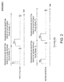
- Fig. 2 illustrates a chart of a waveform and transmission-and-reception periods of pulse signals transmitted in a first detection and a chart of a waveform and transmission-and-reception periods of pulse signals transmitted in a second detection.
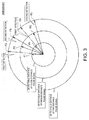
- Fig. 3 is a view illustrating directions and detectable distances of the pulse signals transmitted in the first and second detections.
- the radar apparatus 1 of this embodiment is a pulse-compression radar.
- the radar apparatus 1 transmits radio waves having a wide pulse width and analyzes reception signals caused by the transmitted radio waves, so as to detect a position and a speed of a target object.
- the radar apparatus 1 includes a radar antenna 11, a transmission and reception unit 12, a signal processor 13, and a display unit 14.
- the radar antenna 11 transmits a microwave configuring a transmission signal and receives echo(es) (reception signal(s), reflection signal(s)) from target object(s) in a surrounding area of the radar antenna 11.
- the radar antenna 11 repeats the transmission and reception while rotating on a particular plane at a given cycle.
- the radar apparatus 1 is capable of detecting target object(s) in a surrounding area of a ship concerned (hereinafter, referred to as "the ship").
- the transmission and reception unit 12 includes a transmission signal generator 21, a local oscillator 22, a transmitter 23, a transmission/reception switch 24, and a frequency converter 25. Note that the transmission and reception unit 12 may be disposed inside the radar antenna 11 or at a radar indicator.
- the transmission signal generator 21 specifies a pulse width, a modulation mode (a frequency modulation width and a frequency change mode), etc., and generates a microwave having a given waveform.
- the local oscillator 22 generates a local signal for converting the microwave generated by the transmission signal generator 21 into a given band range.
- the transmitter 23 generates the transmission signal based on the microwave generated by the transmission signal generator 21 and the local signal and outputs the transmission signal to the transmission/reception switch 24.
- the transmission/reception switch 24 switches the transmission and the reception of the microwave therebetween. Specifically, to externally transmit the transmission signal, the transmission/reception switch 24 outputs the transmission signal outputted by the transmitter 23 to the radar antenna 11. On the other hand, to externally receive the reception signal, the transmission/reception switch 24 outputs the reception signal from the radar antenna 11 to the frequency converter 25.
- Fig. 2 schematically illustrates the transmission signals transmitted by the radar antenna 11 of this embodiment.
- the radar apparatus 1 alternately executes first and second detections.
- Fig. 3 illustrates the transmission time intervals of the pulse signals to be longer than actual intervals for the sake of convenience.
- the three circles indicate, from the inside, a detectable distance of a pulse signal for close distance range (close distance pulse signal) P1, a detectable distance of a pulse signal for medium distance range (medium distance pulse signal) P2, and a detectable distance of a pulse signal for far distance range (far distance pulse signal) P3. Note that these detectable distances are also illustrated with different lengths from actual detectable distances for the sake of convenience.
- the first detection includes transmission and reception processings of the close distance pulse signal P1 and transmission and reception processings of the far distance pulse signal P3.
- the second detection includes transmission and reception processings of the medium distance pulse signal P2 and transmission and reception processings of the far distance pulse signal P3.
- the close distance pulse signal P1 is a signal for detecting a close distance range.
- the close distance pulse signal P1 is a non-modulated pulse and has the narrowest pulse width among the three pulse signals.
- the medium distance pulse signal P2 is a signal for detecting a medium distance range (between the close distance range and the far distance range).
- the medium distance pulse signal P2 is a modulated pulse.
- the pulse width of the medium distance pulse signal P2 is wider than the close distance pulse signal P1 and narrower than the far distance pulse signal P3.
- the far distance pulse signal P3 is a modulated pulse and has the widest pulse width among the three pulse signals. Further the medium and far distance pulse signals P2 and P3 have the same frequency modulation width. Thus, they will have the same pulse width after a pulse compression (described later). Note that the frequency change mode may be linear or non-linear. Moreover, the far distance pulse signal P3 is used in both of the first and second detections, and the properties (pulse width, modulation mode, amplitude, etc.) of the far distance pulse signal P3 are the same therein.
- a transmission-and-reception period T1 of the close distance pulse signal P1 is the shortest period among those of the three pulse signals.
- a transmission-and-reception period T2 of the medium distance pulse signal P2 is longer than T1.
- a transmission-and-reception period T3 of the far distance pulse signal P3 is the longest period among those of the three pulse signals.
- the frequency converter 25 converts the reception signal into a baseband by using the local signal generated by the local oscillator 22.
- the reception signal converted by the frequency converter 25 is outputted to the signal processor 13.
- the signal processor 13 includes an A/D converter 31, a quadrature detecting module 32, a pulse compressing module 33, a reception data memory 34, a pulse integrating module 35, and a display processing module 36.
- the A/D converter 31 converts the reception signal from an analog signal into a digital signal from a single signal.
- the quadrature detecting module 32 divides the inputted reception signal into two signal components and shifts a phase of one of the signal components by 90°. Thus, the quadrature detecting module 32 generates two signal components of an I signal and a Q signal.
- the pulse compressing module 33 takes in the I and Q signals and compresses pulse widths thereof. Thus, even with a microwave which causes a weak output, reception data with substantially the same intensity as that obtained by a conventional magnetron radar can be obtained. Note that the pulse compressing module 33 performs different processing according to the inputted signal. For example, when the reception signal of the close distance pulse signal P1 is inputted, since the pulse compression is not required, no particular processing is performed. When the reception signal of the medium distance pulse signal P2 is inputted, the pulse width thereof is compressed in a mode according to the modulation mode of the medium distance pulse signal P2. The pulse width of the far distance pulse signal P3 is also similarly compressed.
- the reception data memory 34 stores a given number of reception data generated by the pulse compressing module 33, for each distance range. Further, when the pulse compressing module 33 newly generates reception data (latest reception data), the reception data stored in the reception data memory 34 is replaced by the latest reception data. Note that, the reception data memory 34 may store a given number of reception data for each kind of pulse signal.
- the pulse integrating module 35 performs a pulse integration based on the reception data stored by the reception data memory 34. Specifically, the pulse integrating module 35 performs the pulse integration of the given number of reception data by one of DFT and FFT, for each distance range. Thus, the pulse integrating module 35 can calculate a detection result. Note that the pulse integrating module 35 may perform the pulse integration for each kind of pulse signal.
- the display processing module 36 generates a radar image (described later) based on the detection result outputted by the pulse integrating module 35.
- Fig. 4 is a chart illustrating pulse signals transmitted in a conventional example (corresponding to JP2008-527391A and JP5398306B ) and transmission-and-reception periods thereof.
- the pulse signals transmitted according to JP2008-527391A and JP5398306B are briefly described. As illustrated in Fig. 4 , in each of the conventional radar apparatuses, the transmission and reception processings for a close distance pulse signal P1, a medium distance pulse signal P2, and a far distance pulse signal P3 are performed in this order, and these processings are repeated. Therefore, each kind of pulse signal is transmitted every three transmissions.
- the pulse signals are radially transmitted by the radar apparatus, and thus, space between the pulse signals in the bearing direction becomes wider as they propagate farther from the radar apparatus. Therefore, the pulse signals may not meet a target object within the far distance range. In this case, the target object within the far distance range is not detected and/or the S/N does not improve much when the pulse integration is performed.
- the far distance pulse signal P3 is transmitted in both of the first and second detections. In other words, the far distance pulse signal P3 is transmitted every other transmission. Therefore, compared to the conventional example in Fig. 4 , the target object within the far distance range can accurately be detected.
- the reflection waves can stably be acquired from a plurality of target objects compared to within the far distance range, and the radar apparatus 1 can detect within the surrounding area thereof without a problem.
- the transmission time interval of the far distance pulse signal P3 is always constant. Therefore, it is required to implement a measure to prevent interference with other radar apparatuses.
- the transmission time interval of the far distance pulse signal P3 is one of T1 and T2, it is not constant. Therefore, interference with the other radar apparatuses can be prevented. Note that, in order to reduce the influence of the interference even more, the transmission time interval between the pulse signals may be slightly varied.
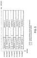
- Fig. 5 illustrates ranges for which the first and second detections are performed. Note that in the following description, the processing of transmitting and receiving the series of (two) pulse signals in each of the first and second detections is referred to as a single sweep.
- the first detection is performed.
- "RECEPTION 1-1” indicates the reception data obtained with the close distance pulse signal P1
- "RECEPTION 1-2” indicates the reception data obtained with the far distance pulse signal P3.
- an undetectable range exists between “RECEPTION 1-1” and "RECEPTION 1-2.” Note that the first detection may be performed so that such an undetectable range does not exist between “RECEPTION 1-1” and "RECEPTION 1-2.”
- the second detection is performed.
- "RECEPTION 2-1" indicates the reception data obtained with the medium distance pulse signal P2
- "RECEPTION 2-2" indicates the reception data obtained with the far distance pulse signal P3.
- an undetectable range exists on a closer distance side of "RECEPTION 2-1.”
- the detectable distance range of the medium distance pulse signal (corresponding to "RECEPTION 2-1") at least partially overlaps with the first undetectable range.
- the detectable distance range of the close distance pulse signal (corresponding to "RECEPTION 1-1”) at least partially overlaps with the second undetectable range.
- the first undetectable range is interpolated by the reception data obtained with the medium distance pulse signal P2 in the second detection ("RECEPTION 2-1"). Specifically, a detection result which would be obtained within the first undetectable range is estimated by performing average value processing on the reception data of the second detection performed immediately previous to and immediately after the first detection concerned.
- the interpolating method of the first undetectable range is arbitrary, and it may be such that the reception data obtained immediately previous to or immediately after the first detection concerned is used, or reception data for a plurality of adjacent second detections obtained immediately previous to or immediately after the first detection concerned may be used.
- the detection result which would be obtained within the first undetectable range may be estimated by performing the pulse integration using the above-described reception data obtained immediately previous to and/or immediately after the first detection concerned.
- the second undetectable range is interpolated by the reception data obtained by the close distance pulse signal P1 in the first detection ("RECEPTION 1-1"). Specifically, a detection result which would be obtained within the second undetectable range is estimated by performing average value processing on the reception data of the first detection performed immediately previous to and immediately after the second detection concerned. Note that, the interpolating method of the second undetectable range is arbitrary, and various methods may be used similarly to the interpolating method of the first undetectable range.
- a plurality of reception data adjacent to each other in the distance direction may be taken into consideration so that a mark of the interpolation performed does not appear on the radar image (a boundary between the interpolated section and the non-interpolated section becomes unapparent). Also between "RECEPTION 2-1" and “RECEPTION 2-2," the reception data may be processed smoothing so that a boundary of two reception data does not appear on the radar image. Particularly since the frequency modulation widths of the medium and far distance pulse signals P2 and P3 are the same as described above, a radar image with no obvious boundary between the medium and far distance ranges can be created.
- the radar apparatus 1 includes the transmission and reception unit 12 and the signal processor 13.
- the transmission and reception unit 12 transmits the close distance pulse signal, the medium distance pulse signal, and the far distance pulse signal in the order of the close distance pulse signal, the far distance pulse signal, the medium distance pulse signal, and then the far distance pulse signal, and receives the reflection waves of the transmitted pulse signals, the far distance pulse signal having the wider pulse width than the close distance pulse signal, the medium distance pulse signal having the pulse width wider than the close distance pulse signal and narrower than the far distance pulse signal.
- the signal processor 13 generates the radar image by using a first detection result (the reception data obtained through the first detection) and a second detection result (the reception data obtained through the second detection), the first detection result being a result of the transmissions and the receptions of the close distance pulse signal and the far distance pulse signal transmitted subsequently to the close distance pulse signal, the second detection result being a result of the transmissions and the receptions of the medium distance pulse signal and the far distance pulse signal transmitted subsequently to the medium distance pulse signal.
- the transmission time interval of the far distance pulse signal P3 can be shortened. Therefore, the target object within the far distance range can accurately be detected.
- the radar image is generated by performing the pulse integration; however, this may be omitted.
- the radar apparatus mounted on the ship is described as an example; however, the present disclosure may be applied to radar apparatuses mounted on other movable bodies (e.g., aircrafts). Further, the present disclosure may be applied to radar apparatuses installed at a beacon, a strait, a port, etc., and having a configuration to detect a surrounding situation by radar echoes.
Landscapes
- Engineering & Computer Science (AREA)
- Radar, Positioning & Navigation (AREA)
- Remote Sensing (AREA)
- Physics & Mathematics (AREA)
- Computer Networks & Wireless Communication (AREA)
- General Physics & Mathematics (AREA)
- Radar Systems Or Details Thereof (AREA)
- Electromagnetism (AREA)
Abstract
Description
- This disclosure mainly relates to a radar apparatus, which transmits pulse signals having different pulse widths to detect a target object within a surrounding area of the radar apparatus.
- Conventionally, pulse-compression radars are known, which transmit pulse signals, receive reflection waves thereof, and perform a pulse compression on the reflection waves, so as to improve distance resolution and S/N (signal-to-noise ratio). In the case of transmitting the pulse signals having the wide pulse width, since the reflection waves cannot be received while the pulse signals are transmitted, a target object within a close distance cannot be detected. Therefore, pulse signals having a narrow pulse width may be transmitted additionally in order to detect target objects within the close distance.
JP2008-527391A JP5398306B - The radar apparatus of
JP2008-527391A - The radar apparatus of
JP5398306B JP2008-527391A - However, in the case of transmitting the pulse signals having the three kinds of pulse widths in order as
JP2008-527391A JP5398306B - The purpose of this disclosure relates to providing a radar apparatus, which is capable of transmitting a plurality of kinds of pulse signals having different pulse widths, and particularly capable of accurately detecting a target object within a far distance range.
- According to one aspect of the present disclosure, a radar apparatus is provided. The radar apparatus includes a transmission and reception unit configured to transmit a close distance pulse signal, a medium distance pulse signal, and a far distance pulse signal in an order of the close distance pulse signal, the far distance pulse signal, the medium distance pulse signal, and then the far distance pulse signal, and receive reflection waves of the transmitted pulse signals, the far distance pulse signal having a wider pulse width than the close distance pulse signal, the medium distance pulse signal having a pulse width wider than the close distance pulse signal and narrower than the far distance pulse signal, and a signal processor configured to generate a radar image by using a first detection result and a second detection result, the first detection result being a result of the transmissions and the receptions of the close distance pulse signal and the far distance pulse signal transmitted subsequently to the close distance pulse signal, the second detection result being a result of the transmissions and the receptions of the medium distance pulse signal and the far distance pulse signal transmitted subsequently to the medium distance pulse signal.
- With this configuration, since the far distance pulse signal is used to obtain both the first and second detection results, a transmission time interval of the far distance pulse signal can be shortened. Therefore, a target object within a far distance range can accurately be detected.
- In the first detection result, a first undetectable range for which a detection result is not obtained may exist between a distance range for which the transmission and reception of the close distance pulse signal is performed and a distance range for which the transmission and reception of the far distance pulse signal is performed.
- With this configuration, the first detection result sufficiently focusing on particular ranges (close and far distance ranges) can be obtained.
- A distance range for which the transmission and reception of the medium distance pulse signal is performed may at least partially overlap with the first undetectable range.
- With this configuration, the range for which the detection result is not obtained in the first detection result can be interpolated by the second detection result.
- The first undetectable range may be interpolated by using the detection result obtained with the medium distance pulse signal.
- With this configuration, the first detection result can be interpolated by the second detection result which is obtained from a bearing close to that from which the first detection result is obtained.
- In the second detection result, a second undetectable range for which a detection result is not obtained may exist within a closer distance range than a distance range for which the transmission and reception of the medium distance pulse signal is performed, and a distance range for which the transmission and reception of the close distance pulse signal is performed may at least partially overlap with the second undetectable range.
- With this configuration, the second detection result sufficiently focusing on particular ranges (medium and far distance ranges) can be obtained. Moreover, the range for which the detection result is not obtained in the second detection result can be interpolated by the first detection result.
- The second undetectable range may be interpolated by using the detection result obtained with the close distance pulse signal.
- With this configuration, the second detection result can be interpolated by the first detection result which is obtained from a bearing close to that from which the second detection result is obtained.
- The close distance pulse signal may be a non-modulated pulse, and the medium and far distance pulse signals may be modulated pulses.
- With this configuration, since the pulse widths of the medium and far distance pulse signals are wide, a pulse compression can suitably be performed by modulation.
- Frequency modulation widths of the medium and far distance pulse signals may be the same.
- With this configuration, the medium and far distance pulse signals have the same pulse width after being compressed, and thus, detection results of the medium and far distance ranges can be synthesized so that a boundary therebetween becomes unapparent.
- Pulse widths and frequency modulation widths of the far distance pulse signal used to obtain the first detection result and the far distance pulse signal used to obtain the second detection result may be the same.
- With this configuration, the first and second detection results can be synthesized so that a boundary therebetween becomes unapparent.
- The present disclosure is illustrated by way of example and not by way of limitation in the figures of the accompanying drawings, in which the like reference numerals indicate like elements and in which:
-
Fig. 1 is a block diagram illustrating a configuration of a radar apparatus according to one embodiment of the present disclosure; -
Fig. 2 illustrates a chart of a waveform and transmission-and-reception periods of pulse signals transmitted in a first detection and a chart of a waveform and transmission-and-reception periods of pulse signals transmitted in a second detection; -
Fig. 3 is a view illustrating directions and detectable distances of the pulse signals transmitted in the first and second detections; -
Fig. 4 is a chart illustrating pulse signals transmitted in a conventional example and transmission-and-reception periods thereof; and -
Fig. 5 is a chart illustrating ranges for which the first and second detections are performed. - Next, one embodiment of the present disclosure is described with reference to the accompanying drawings. In the following embodiment, an example is illustrated in which the present disclosure is applied to a ship. However, the present disclosure may be applied to any kinds of vehicles having a rudder or a similar steering device, such as other watercrafts including boats, vessels, and submarines, as well as land vehicles, airplanes and spaceships.
Fig. 1 is a block diagram illustrating a configuration of a radar apparatus 1 according to this embodiment of this disclosure.Fig. 2 illustrates a chart of a waveform and transmission-and-reception periods of pulse signals transmitted in a first detection and a chart of a waveform and transmission-and-reception periods of pulse signals transmitted in a second detection.Fig. 3 is a view illustrating directions and detectable distances of the pulse signals transmitted in the first and second detections. - The radar apparatus 1 of this embodiment is a pulse-compression radar. The radar apparatus 1 transmits radio waves having a wide pulse width and analyzes reception signals caused by the transmitted radio waves, so as to detect a position and a speed of a target object.
- As illustrated in
Fig. 1 , the radar apparatus 1 includes aradar antenna 11, a transmission andreception unit 12, asignal processor 13, and adisplay unit 14. - The
radar antenna 11 transmits a microwave configuring a transmission signal and receives echo(es) (reception signal(s), reflection signal(s)) from target object(s) in a surrounding area of theradar antenna 11. Theradar antenna 11 repeats the transmission and reception while rotating on a particular plane at a given cycle. Thus, the radar apparatus 1 is capable of detecting target object(s) in a surrounding area of a ship concerned (hereinafter, referred to as "the ship"). - The transmission and
reception unit 12 includes atransmission signal generator 21, alocal oscillator 22, atransmitter 23, a transmission/reception switch 24, and afrequency converter 25. Note that the transmission andreception unit 12 may be disposed inside theradar antenna 11 or at a radar indicator. - The
transmission signal generator 21 specifies a pulse width, a modulation mode (a frequency modulation width and a frequency change mode), etc., and generates a microwave having a given waveform. Thelocal oscillator 22 generates a local signal for converting the microwave generated by thetransmission signal generator 21 into a given band range. Thetransmitter 23 generates the transmission signal based on the microwave generated by thetransmission signal generator 21 and the local signal and outputs the transmission signal to the transmission/reception switch 24. - The transmission/
reception switch 24 switches the transmission and the reception of the microwave therebetween. Specifically, to externally transmit the transmission signal, the transmission/reception switch 24 outputs the transmission signal outputted by thetransmitter 23 to theradar antenna 11. On the other hand, to externally receive the reception signal, the transmission/reception switch 24 outputs the reception signal from theradar antenna 11 to thefrequency converter 25. -
Fig. 2 schematically illustrates the transmission signals transmitted by theradar antenna 11 of this embodiment. As illustrated inFigs. 2 and3 , the radar apparatus 1 alternately executes first and second detections. Note thatFig. 3 illustrates the transmission time intervals of the pulse signals to be longer than actual intervals for the sake of convenience. Further inFig. 3 , the three circles indicate, from the inside, a detectable distance of a pulse signal for close distance range (close distance pulse signal) P1, a detectable distance of a pulse signal for medium distance range (medium distance pulse signal) P2, and a detectable distance of a pulse signal for far distance range (far distance pulse signal) P3. Note that these detectable distances are also illustrated with different lengths from actual detectable distances for the sake of convenience. - The first detection includes transmission and reception processings of the close distance pulse signal P1 and transmission and reception processings of the far distance pulse signal P3. The second detection includes transmission and reception processings of the medium distance pulse signal P2 and transmission and reception processings of the far distance pulse signal P3.
- The close distance pulse signal P1 is a signal for detecting a close distance range. The close distance pulse signal P1 is a non-modulated pulse and has the narrowest pulse width among the three pulse signals.
- The medium distance pulse signal P2 is a signal for detecting a medium distance range (between the close distance range and the far distance range). The medium distance pulse signal P2 is a modulated pulse. The pulse width of the medium distance pulse signal P2 is wider than the close distance pulse signal P1 and narrower than the far distance pulse signal P3.
- The far distance pulse signal P3 is a modulated pulse and has the widest pulse width among the three pulse signals. Further the medium and far distance pulse signals P2 and P3 have the same frequency modulation width. Thus, they will have the same pulse width after a pulse compression (described later). Note that the frequency change mode may be linear or non-linear. Moreover, the far distance pulse signal P3 is used in both of the first and second detections, and the properties (pulse width, modulation mode, amplitude, etc.) of the far distance pulse signal P3 are the same therein.
- With the close distance pulse signal P1, since the pulse width is narrow and the purpose of using the signal P1 is to receive a reflection wave from a target object within the close distance range, a waiting time length for the reception is short. Therefore, a transmission-and-reception period T1 of the close distance pulse signal P1 is the shortest period among those of the three pulse signals. With the medium distance pulse signal P2, since the pulse width is wider than the close distance pulse signal P1 and a waiting time for the reception lasts until a reflection wave from a target object within the medium distance range is received, a transmission-and-reception period T2 of the medium distance pulse signal P2 is longer than T1. Similarly, a transmission-and-reception period T3 of the far distance pulse signal P3 is the longest period among those of the three pulse signals. Thus, a relationship of T1<T2<T3 is established.
- The
frequency converter 25 converts the reception signal into a baseband by using the local signal generated by thelocal oscillator 22. The reception signal converted by thefrequency converter 25 is outputted to thesignal processor 13. - The
signal processor 13 includes an A/D converter 31, aquadrature detecting module 32, apulse compressing module 33, areception data memory 34, apulse integrating module 35, and adisplay processing module 36. - The A/
D converter 31 converts the reception signal from an analog signal into a digital signal from a single signal. - The
quadrature detecting module 32 divides the inputted reception signal into two signal components and shifts a phase of one of the signal components by 90°. Thus, thequadrature detecting module 32 generates two signal components of an I signal and a Q signal. - The
pulse compressing module 33 takes in the I and Q signals and compresses pulse widths thereof. Thus, even with a microwave which causes a weak output, reception data with substantially the same intensity as that obtained by a conventional magnetron radar can be obtained. Note that thepulse compressing module 33 performs different processing according to the inputted signal. For example, when the reception signal of the close distance pulse signal P1 is inputted, since the pulse compression is not required, no particular processing is performed. When the reception signal of the medium distance pulse signal P2 is inputted, the pulse width thereof is compressed in a mode according to the modulation mode of the medium distance pulse signal P2. The pulse width of the far distance pulse signal P3 is also similarly compressed. - The
reception data memory 34 stores a given number of reception data generated by thepulse compressing module 33, for each distance range. Further, when thepulse compressing module 33 newly generates reception data (latest reception data), the reception data stored in thereception data memory 34 is replaced by the latest reception data. Note that, thereception data memory 34 may store a given number of reception data for each kind of pulse signal. - The
pulse integrating module 35 performs a pulse integration based on the reception data stored by thereception data memory 34. Specifically, thepulse integrating module 35 performs the pulse integration of the given number of reception data by one of DFT and FFT, for each distance range. Thus, thepulse integrating module 35 can calculate a detection result. Note that thepulse integrating module 35 may perform the pulse integration for each kind of pulse signal. - The
display processing module 36 generates a radar image (described later) based on the detection result outputted by thepulse integrating module 35. - Next, characteristics of the pulse signals transmitted by the radar apparatus 1 of this embodiment are described with reference to
Figs. 2 to 4 .Fig. 4 is a chart illustrating pulse signals transmitted in a conventional example (corresponding toJP2008-527391A JP5398306B - First, the pulse signals transmitted according to
JP2008-527391A JP5398306B Fig. 4 , in each of the conventional radar apparatuses, the transmission and reception processings for a close distance pulse signal P1, a medium distance pulse signal P2, and a far distance pulse signal P3 are performed in this order, and these processings are repeated. Therefore, each kind of pulse signal is transmitted every three transmissions. - Here, the pulse signals are radially transmitted by the radar apparatus, and thus, space between the pulse signals in the bearing direction becomes wider as they propagate farther from the radar apparatus. Therefore, the pulse signals may not meet a target object within the far distance range. In this case, the target object within the far distance range is not detected and/or the S/N does not improve much when the pulse integration is performed.
- In this regard, in this embodiment, the far distance pulse signal P3 is transmitted in both of the first and second detections. In other words, the far distance pulse signal P3 is transmitted every other transmission. Therefore, compared to the conventional example in
Fig. 4 , the target object within the far distance range can accurately be detected. - Additionally in this embodiment, the close and medium distance pulse signals
- P1 and P2 are transmitted every four transmissions. However, the space between the pulse signals in the bearing direction does not become excessively wide within the close and medium distance ranges as described above. Therefore, the reflection waves can stably be acquired from a plurality of target objects compared to within the far distance range, and the radar apparatus 1 can detect within the surrounding area thereof without a problem.
- Further with the conventional radar apparatus in
Fig. 4 , the transmission time interval of the far distance pulse signal P3 is always constant. Therefore, it is required to implement a measure to prevent interference with other radar apparatuses. In this regard, in this embodiment, since the transmission time interval of the far distance pulse signal P3 is one of T1 and T2, it is not constant. Therefore, interference with the other radar apparatuses can be prevented. Note that, in order to reduce the influence of the interference even more, the transmission time interval between the pulse signals may be slightly varied. - Next, a method of generating the reception data and the radar image which can be obtained through the first and second detections is described with reference to
Fig. 5. Fig. 5 illustrates ranges for which the first and second detections are performed. Note that in the following description, the processing of transmitting and receiving the series of (two) pulse signals in each of the first and second detections is referred to as a single sweep. - In (odd number)-th sweeps, the first detection is performed. In
Fig. 5 , "RECEPTION 1-1" indicates the reception data obtained with the close distance pulse signal P1 and "RECEPTION 1-2" indicates the reception data obtained with the far distance pulse signal P3. In the first detection, since the medium distance pulse signal P2 is not transmitted, an undetectable range (first undetectable range) exists between "RECEPTION 1-1" and "RECEPTION 1-2." Note that the first detection may be performed so that such an undetectable range does not exist between "RECEPTION 1-1" and "RECEPTION 1-2." - In (even number)-th sweeps, the second detection is performed. In
Fig. 5 , "RECEPTION 2-1" indicates the reception data obtained with the medium distance pulse signal P2 and "RECEPTION 2-2" indicates the reception data obtained with the far distance pulse signal P3. In the second detection, since the close distance pulse signal P1 is not transmitted, an undetectable range (second undetectable range) exists on a closer distance side of "RECEPTION 2-1." Note that the detectable distance range of the medium distance pulse signal (corresponding to "RECEPTION 2-1") at least partially overlaps with the first undetectable range. Further, the detectable distance range of the close distance pulse signal (corresponding to "RECEPTION 1-1") at least partially overlaps with the second undetectable range. - The first undetectable range is interpolated by the reception data obtained with the medium distance pulse signal P2 in the second detection ("RECEPTION 2-1"). Specifically, a detection result which would be obtained within the first undetectable range is estimated by performing average value processing on the reception data of the second detection performed immediately previous to and immediately after the first detection concerned. Note that, the interpolating method of the first undetectable range is arbitrary, and it may be such that the reception data obtained immediately previous to or immediately after the first detection concerned is used, or reception data for a plurality of adjacent second detections obtained immediately previous to or immediately after the first detection concerned may be used. Alternatively, the detection result which would be obtained within the first undetectable range may be estimated by performing the pulse integration using the above-described reception data obtained immediately previous to and/or immediately after the first detection concerned.
- The second undetectable range is interpolated by the reception data obtained by the close distance pulse signal P1 in the first detection ("RECEPTION 1-1"). Specifically, a detection result which would be obtained within the second undetectable range is estimated by performing average value processing on the reception data of the first detection performed immediately previous to and immediately after the second detection concerned. Note that, the interpolating method of the second undetectable range is arbitrary, and various methods may be used similarly to the interpolating method of the first undetectable range.
- Further, when interpolating the first and second undetectable ranges, a plurality of reception data adjacent to each other in the distance direction may be taken into consideration so that a mark of the interpolation performed does not appear on the radar image (a boundary between the interpolated section and the non-interpolated section becomes unapparent). Also between "RECEPTION 2-1" and "RECEPTION 2-2," the reception data may be processed smoothing so that a boundary of two reception data does not appear on the radar image. Particularly since the frequency modulation widths of the medium and far distance pulse signals P2 and P3 are the same as described above, a radar image with no obvious boundary between the medium and far distance ranges can be created. Note that since the properties of the far distance pulse signal P3 are the same in the first and second detections, processing of synthesizing the detection result of the far distance range in the first detection with the detection result of the far distance range in the second detection becomes easy, and also unbalanced illustration of the adjacent sections in the bearing direction in the radar image generated by the synthesizing can be eliminated.
- As described above, the radar apparatus 1 includes the transmission and
reception unit 12 and thesignal processor 13. The transmission andreception unit 12 transmits the close distance pulse signal, the medium distance pulse signal, and the far distance pulse signal in the order of the close distance pulse signal, the far distance pulse signal, the medium distance pulse signal, and then the far distance pulse signal, and receives the reflection waves of the transmitted pulse signals, the far distance pulse signal having the wider pulse width than the close distance pulse signal, the medium distance pulse signal having the pulse width wider than the close distance pulse signal and narrower than the far distance pulse signal. Thesignal processor 13 generates the radar image by using a first detection result (the reception data obtained through the first detection) and a second detection result (the reception data obtained through the second detection), the first detection result being a result of the transmissions and the receptions of the close distance pulse signal and the far distance pulse signal transmitted subsequently to the close distance pulse signal, the second detection result being a result of the transmissions and the receptions of the medium distance pulse signal and the far distance pulse signal transmitted subsequently to the medium distance pulse signal. - Since the far distance pulse signal P3 is transmitted in both of the first and second detections, the transmission time interval of the far distance pulse signal P3 can be shortened. Therefore, the target object within the far distance range can accurately be detected.
- Although one embodiment of the present disclosure is described above, the above configuration may be modified as follows.
- In the above embodiment, the radar image is generated by performing the pulse integration; however, this may be omitted.
- In the above embodiment, the radar apparatus mounted on the ship is described as an example; however, the present disclosure may be applied to radar apparatuses mounted on other movable bodies (e.g., aircrafts). Further, the present disclosure may be applied to radar apparatuses installed at a beacon, a strait, a port, etc., and having a configuration to detect a surrounding situation by radar echoes.
Claims (9)
- A radar apparatus (1), comprising:a transmission and reception unit (12) configured to transmit a close distance pulse signal, a medium distance pulse signal, and a far distance pulse signal in an order of the close distance pulse signal, the far distance pulse signal, the medium distance pulse signal, and then the far distance pulse signal, and receive reflection waves of the transmitted pulse signals, the far distance pulse signal having a wider pulse width than the close distance pulse signal, the medium distance pulse signal having a pulse width wider than the close distance pulse signal and narrower than the far distance pulse signal; anda signal processor (13) configured to generate a radar image by using a first detection result and a second detection result, the first detection result being a result of the transmissions and the receptions of the close distance pulse signal and the far distance pulse signal transmitted subsequently to the close distance pulse signal, the second detection result being a result of the transmissions and the receptions of the medium distance pulse signal and the far distance pulse signal transmitted subsequently to the medium distance pulse signal.
- The radar apparatus (1) of claim 1, wherein in the first detection result, a first undetectable range for which a detection result is not obtained exists between a distance range for which the transmission and reception of the close distance pulse signal is performed and a distance range for which the transmission and reception of the far distance pulse signal is performed.
- The radar apparatus (1) of claim 2, wherein a distance range for which the transmission and reception of the medium distance pulse signal is performed at least partially overlaps with the first undetectable range.
- The radar apparatus (1) of claim 3, wherein the first undetectable range is interpolated by using the detection result obtained with the medium distance pulse signal.
- The radar apparatus (1) of any one of claims 1 to 4, wherein in the second detection result, a second undetectable range for which a detection result is not obtained exists within a closer distance range than a distance range for which the transmission and reception of the medium distance pulse signal is performed, and a distance range for which the transmission and reception of the close distance pulse signal is performed at least partially overlaps with the second undetectable range.
- The radar apparatus (1) of claim 5, wherein the second undetectable range is interpolated by using the detection result obtained with the close distance pulse signal.
- The radar apparatus (1) of any one of claims 1 to 6, wherein the close distance pulse signal is a non-modulated pulse, and the medium and far distance pulse signals are modulated pulses.
- The radar apparatus (1) of claim 7, wherein frequency modulation widths of the medium and far distance pulse signals are the same.
- The radar apparatus (1) of any one of claims 1 to 8, wherein pulse widths and frequency modulation widths of the far distance pulse signal used to obtain the first detection result and the far distance pulse signal used to obtain the second detection result are the same.
Applications Claiming Priority (1)
| Application Number | Priority Date | Filing Date | Title |
|---|---|---|---|
| JP2015032630A JP6438321B2 (en) | 2015-02-23 | 2015-02-23 | Radar equipment |
Publications (2)
| Publication Number | Publication Date |
|---|---|
| EP3059609A1 true EP3059609A1 (en) | 2016-08-24 |
| EP3059609B1 EP3059609B1 (en) | 2017-12-27 |
Family
ID=55404631
Family Applications (1)
| Application Number | Title | Priority Date | Filing Date |
|---|---|---|---|
| EP16156471.1A Active EP3059609B1 (en) | 2015-02-23 | 2016-02-19 | Radar apparatus |
Country Status (3)
| Country | Link |
|---|---|
| US (1) | US10048364B2 (en) |
| EP (1) | EP3059609B1 (en) |
| JP (1) | JP6438321B2 (en) |
Cited By (1)
| Publication number | Priority date | Publication date | Assignee | Title |
|---|---|---|---|---|
| US12366641B2 (en) | 2018-12-18 | 2025-07-22 | Sony Semiconductor Solutions Corporation | Ranging apparatus and measuring apparatus |
Families Citing this family (5)
| Publication number | Priority date | Publication date | Assignee | Title |
|---|---|---|---|---|
| JP6829121B2 (en) * | 2017-03-22 | 2021-02-10 | 古野電気株式会社 | Radar control device and radar transmission power control method |
| KR102047278B1 (en) * | 2017-06-01 | 2019-11-21 | 주식회사 에스원 | Ladar detector based reflector and operating method thereof |
| JP6928838B2 (en) * | 2017-12-28 | 2021-09-01 | 古河電気工業株式会社 | Radar device and object detection method for radar device |
| JP7362301B2 (en) * | 2019-06-05 | 2023-10-17 | 日本信号株式会社 | underground radar equipment |
| US12230857B2 (en) | 2021-11-30 | 2025-02-18 | Navico, Inc. | Radar waveguide and choke assembly |
Citations (4)
| Publication number | Priority date | Publication date | Assignee | Title |
|---|---|---|---|---|
| JP2008527391A (en) | 2005-01-19 | 2008-07-24 | スミスズ グループ ピーエルシー | Radar device |
| US20110187579A1 (en) * | 2010-02-01 | 2011-08-04 | Yasunobu Asada | Method and device for transmission, method and device for reception, and method and device for detecting target object |
| EP2677341A1 (en) * | 2012-06-21 | 2013-12-25 | Furuno Electric Co., Ltd. | Apparatus and method for detecting target object |
| JP5398306B2 (en) | 2009-03-04 | 2014-01-29 | 古野電気株式会社 | Radar equipment |
Family Cites Families (9)
| Publication number | Priority date | Publication date | Assignee | Title |
|---|---|---|---|---|
| DE1566867B2 (en) * | 1967-01-14 | 1970-10-29 | Electroacustic Gmbh, 2300 Kiel | Method and device for underwater echo sounding |
| US7358892B2 (en) * | 2005-04-04 | 2008-04-15 | Raytheon Company | System and method for coherently combining a plurality of radars |
| US7773028B2 (en) * | 2006-12-06 | 2010-08-10 | Raytheon Company | Method and system for concatenation of radar pulses |
| JP2009031165A (en) * | 2007-07-27 | 2009-02-12 | Toyota Motor Corp | Pulse radar equipment |
| JP2011013182A (en) * | 2009-07-06 | 2011-01-20 | Furuno Electric Co Ltd | Target detector and method of detecting target |
| KR101710469B1 (en) * | 2009-12-17 | 2017-02-28 | 삼성전자주식회사 | The method for detecting a radar signal |
| US9157985B1 (en) * | 2012-02-08 | 2015-10-13 | Bae Systems Information And Electronic Systems Integration Inc. | Signal agnostic matched filter parameter estimator |
| EP3171201B1 (en) * | 2012-03-07 | 2018-05-09 | Safran Vectronix AG | Distance sensor |
| US10120069B2 (en) * | 2014-08-19 | 2018-11-06 | Navico Holding As | Multiple ranges for pulse compression radar |
-
2015
- 2015-02-23 JP JP2015032630A patent/JP6438321B2/en active Active
-
2016
- 2016-02-19 EP EP16156471.1A patent/EP3059609B1/en active Active
- 2016-02-19 US US15/048,138 patent/US10048364B2/en active Active
Patent Citations (4)
| Publication number | Priority date | Publication date | Assignee | Title |
|---|---|---|---|---|
| JP2008527391A (en) | 2005-01-19 | 2008-07-24 | スミスズ グループ ピーエルシー | Radar device |
| JP5398306B2 (en) | 2009-03-04 | 2014-01-29 | 古野電気株式会社 | Radar equipment |
| US20110187579A1 (en) * | 2010-02-01 | 2011-08-04 | Yasunobu Asada | Method and device for transmission, method and device for reception, and method and device for detecting target object |
| EP2677341A1 (en) * | 2012-06-21 | 2013-12-25 | Furuno Electric Co., Ltd. | Apparatus and method for detecting target object |
Cited By (1)
| Publication number | Priority date | Publication date | Assignee | Title |
|---|---|---|---|---|
| US12366641B2 (en) | 2018-12-18 | 2025-07-22 | Sony Semiconductor Solutions Corporation | Ranging apparatus and measuring apparatus |
Also Published As
| Publication number | Publication date |
|---|---|
| EP3059609B1 (en) | 2017-12-27 |
| US20160245908A1 (en) | 2016-08-25 |
| JP6438321B2 (en) | 2018-12-12 |
| US10048364B2 (en) | 2018-08-14 |
| JP2016156620A (en) | 2016-09-01 |
Similar Documents
| Publication | Publication Date | Title |
|---|---|---|
| EP3059609B1 (en) | Radar apparatus | |
| CN109099991B (en) | Filling level measuring device and filling level determination method | |
| JP6818541B2 (en) | Radar device and positioning method | |
| US10914818B2 (en) | Angle-resolving FMCW radar sensor | |
| AU2006248845B2 (en) | Marine radar apparatus | |
| US10386472B2 (en) | Radar device signal processing device and signal processing method for radar device | |
| DK2821808T3 (en) | RADAR DEVICE AND RADAR SIGNAL TREATMENT PROCEDURE | |
| US9470784B2 (en) | Radar device | |
| US9689979B2 (en) | Pulse signal setting device, radar apparatus, method and program of setting pulse signal | |
| US7683824B2 (en) | Radar apparatus | |
| KR20150094240A (en) | Apparatus and method of detecting target using radar | |
| JPH0727021B2 (en) | Synthetic aperture radar device | |
| JP5660973B2 (en) | Radar equipment | |
| US20130147655A1 (en) | Radar apparatus | |
| JP5656505B2 (en) | Radar equipment | |
| CN103513245A (en) | Radar device and method of processing reflection signal | |
| US9075142B2 (en) | Device and method for selecting signal, and radar apparatus | |
| WO2020218925A1 (en) | Processing of radar signals for fmcw radar | |
| JP2010169671A (en) | Radar device | |
| JP2013167580A (en) | Target speed measuring device, signal processing apparatus, radar device, target speed measuring method, and program | |
| JP3641628B2 (en) | Automotive pulse radar equipment | |
| JP3799337B2 (en) | FM-CW radar apparatus and interference wave removing method in the apparatus | |
| CN112415479B (en) | Frequency diversity technology-based continuous wave navigation radar spectrum pairing method | |
| JP2013113723A (en) | Radar system | |
| JP2009264788A (en) | Pulse radar device |
Legal Events
| Date | Code | Title | Description |
|---|---|---|---|
| PUAI | Public reference made under article 153(3) epc to a published international application that has entered the european phase |
Free format text: ORIGINAL CODE: 0009012 |
|
| AK | Designated contracting states |
Kind code of ref document: A1 Designated state(s): AL AT BE BG CH CY CZ DE DK EE ES FI FR GB GR HR HU IE IS IT LI LT LU LV MC MK MT NL NO PL PT RO RS SE SI SK SM TR |
|
| AX | Request for extension of the european patent |
Extension state: BA ME |
|
| STAA | Information on the status of an ep patent application or granted ep patent |
Free format text: STATUS: REQUEST FOR EXAMINATION WAS MADE |
|
| 17P | Request for examination filed |
Effective date: 20170206 |
|
| RBV | Designated contracting states (corrected) |
Designated state(s): AL AT BE BG CH CY CZ DE DK EE ES FI FR GB GR HR HU IE IS IT LI LT LU LV MC MK MT NL NO PL PT RO RS SE SI SK SM TR |
|
| GRAP | Despatch of communication of intention to grant a patent |
Free format text: ORIGINAL CODE: EPIDOSNIGR1 |
|
| STAA | Information on the status of an ep patent application or granted ep patent |
Free format text: STATUS: GRANT OF PATENT IS INTENDED |
|
| RIC1 | Information provided on ipc code assigned before grant |
Ipc: G01S 13/10 20060101AFI20170628BHEP Ipc: G01S 13/28 20060101ALI20170628BHEP Ipc: G01S 13/22 20060101ALN20170628BHEP Ipc: G01S 13/30 20060101ALI20170628BHEP |
|
| RIC1 | Information provided on ipc code assigned before grant |
Ipc: G01S 13/10 20060101AFI20170703BHEP Ipc: G01S 13/30 20060101ALI20170703BHEP Ipc: G01S 13/28 20060101ALI20170703BHEP Ipc: G01S 13/22 20060101ALN20170703BHEP |
|
| INTG | Intention to grant announced |
Effective date: 20170719 |
|
| GRAA | (expected) grant |
Free format text: ORIGINAL CODE: 0009210 |
|
| STAA | Information on the status of an ep patent application or granted ep patent |
Free format text: STATUS: THE PATENT HAS BEEN GRANTED |
|
| GRAS | Grant fee paid |
Free format text: ORIGINAL CODE: EPIDOSNIGR3 |
|
| AK | Designated contracting states |
Kind code of ref document: B1 Designated state(s): AL AT BE BG CH CY CZ DE DK EE ES FI FR GB GR HR HU IE IS IT LI LT LU LV MC MK MT NL NO PL PT RO RS SE SI SK SM TR |
|
| REG | Reference to a national code |
Ref country code: GB Ref legal event code: FG4D |
|
| REG | Reference to a national code |
Ref country code: CH Ref legal event code: EP |
|
| REG | Reference to a national code |
Ref country code: AT Ref legal event code: REF Ref document number: 958766 Country of ref document: AT Kind code of ref document: T Effective date: 20180115 |
|
| REG | Reference to a national code |
Ref country code: IE Ref legal event code: FG4D |
|
| REG | Reference to a national code |
Ref country code: DE Ref legal event code: R096 Ref document number: 602016001180 Country of ref document: DE |
|
| PG25 | Lapsed in a contracting state [announced via postgrant information from national office to epo] |
Ref country code: NO Free format text: LAPSE BECAUSE OF FAILURE TO SUBMIT A TRANSLATION OF THE DESCRIPTION OR TO PAY THE FEE WITHIN THE PRESCRIBED TIME-LIMIT Effective date: 20180327 Ref country code: FI Free format text: LAPSE BECAUSE OF FAILURE TO SUBMIT A TRANSLATION OF THE DESCRIPTION OR TO PAY THE FEE WITHIN THE PRESCRIBED TIME-LIMIT Effective date: 20171227 Ref country code: LT Free format text: LAPSE BECAUSE OF FAILURE TO SUBMIT A TRANSLATION OF THE DESCRIPTION OR TO PAY THE FEE WITHIN THE PRESCRIBED TIME-LIMIT Effective date: 20171227 |
|
| REG | Reference to a national code |
Ref country code: NL Ref legal event code: MP Effective date: 20171227 |
|
| REG | Reference to a national code |
Ref country code: LT Ref legal event code: MG4D |
|
| REG | Reference to a national code |
Ref country code: AT Ref legal event code: MK05 Ref document number: 958766 Country of ref document: AT Kind code of ref document: T Effective date: 20171227 |
|
| PG25 | Lapsed in a contracting state [announced via postgrant information from national office to epo] |
Ref country code: HR Free format text: LAPSE BECAUSE OF FAILURE TO SUBMIT A TRANSLATION OF THE DESCRIPTION OR TO PAY THE FEE WITHIN THE PRESCRIBED TIME-LIMIT Effective date: 20171227 Ref country code: BG Free format text: LAPSE BECAUSE OF FAILURE TO SUBMIT A TRANSLATION OF THE DESCRIPTION OR TO PAY THE FEE WITHIN THE PRESCRIBED TIME-LIMIT Effective date: 20180327 Ref country code: GR Free format text: LAPSE BECAUSE OF FAILURE TO SUBMIT A TRANSLATION OF THE DESCRIPTION OR TO PAY THE FEE WITHIN THE PRESCRIBED TIME-LIMIT Effective date: 20180328 Ref country code: LV Free format text: LAPSE BECAUSE OF FAILURE TO SUBMIT A TRANSLATION OF THE DESCRIPTION OR TO PAY THE FEE WITHIN THE PRESCRIBED TIME-LIMIT Effective date: 20171227 Ref country code: RS Free format text: LAPSE BECAUSE OF FAILURE TO SUBMIT A TRANSLATION OF THE DESCRIPTION OR TO PAY THE FEE WITHIN THE PRESCRIBED TIME-LIMIT Effective date: 20171227 |
|
| PG25 | Lapsed in a contracting state [announced via postgrant information from national office to epo] |
Ref country code: NL Free format text: LAPSE BECAUSE OF FAILURE TO SUBMIT A TRANSLATION OF THE DESCRIPTION OR TO PAY THE FEE WITHIN THE PRESCRIBED TIME-LIMIT Effective date: 20171227 |
|
| PG25 | Lapsed in a contracting state [announced via postgrant information from national office to epo] |
Ref country code: CZ Free format text: LAPSE BECAUSE OF FAILURE TO SUBMIT A TRANSLATION OF THE DESCRIPTION OR TO PAY THE FEE WITHIN THE PRESCRIBED TIME-LIMIT Effective date: 20171227 Ref country code: SK Free format text: LAPSE BECAUSE OF FAILURE TO SUBMIT A TRANSLATION OF THE DESCRIPTION OR TO PAY THE FEE WITHIN THE PRESCRIBED TIME-LIMIT Effective date: 20171227 Ref country code: CY Free format text: LAPSE BECAUSE OF FAILURE TO SUBMIT A TRANSLATION OF THE DESCRIPTION OR TO PAY THE FEE WITHIN THE PRESCRIBED TIME-LIMIT Effective date: 20171227 Ref country code: EE Free format text: LAPSE BECAUSE OF FAILURE TO SUBMIT A TRANSLATION OF THE DESCRIPTION OR TO PAY THE FEE WITHIN THE PRESCRIBED TIME-LIMIT Effective date: 20171227 Ref country code: ES Free format text: LAPSE BECAUSE OF FAILURE TO SUBMIT A TRANSLATION OF THE DESCRIPTION OR TO PAY THE FEE WITHIN THE PRESCRIBED TIME-LIMIT Effective date: 20171227 |
|
| PG25 | Lapsed in a contracting state [announced via postgrant information from national office to epo] |
Ref country code: IT Free format text: LAPSE BECAUSE OF FAILURE TO SUBMIT A TRANSLATION OF THE DESCRIPTION OR TO PAY THE FEE WITHIN THE PRESCRIBED TIME-LIMIT Effective date: 20171227 Ref country code: SM Free format text: LAPSE BECAUSE OF FAILURE TO SUBMIT A TRANSLATION OF THE DESCRIPTION OR TO PAY THE FEE WITHIN THE PRESCRIBED TIME-LIMIT Effective date: 20171227 Ref country code: AT Free format text: LAPSE BECAUSE OF FAILURE TO SUBMIT A TRANSLATION OF THE DESCRIPTION OR TO PAY THE FEE WITHIN THE PRESCRIBED TIME-LIMIT Effective date: 20171227 Ref country code: PL Free format text: LAPSE BECAUSE OF FAILURE TO SUBMIT A TRANSLATION OF THE DESCRIPTION OR TO PAY THE FEE WITHIN THE PRESCRIBED TIME-LIMIT Effective date: 20171227 Ref country code: IS Free format text: LAPSE BECAUSE OF FAILURE TO SUBMIT A TRANSLATION OF THE DESCRIPTION OR TO PAY THE FEE WITHIN THE PRESCRIBED TIME-LIMIT Effective date: 20180427 Ref country code: RO Free format text: LAPSE BECAUSE OF FAILURE TO SUBMIT A TRANSLATION OF THE DESCRIPTION OR TO PAY THE FEE WITHIN THE PRESCRIBED TIME-LIMIT Effective date: 20171227 |
|
| PG25 | Lapsed in a contracting state [announced via postgrant information from national office to epo] |
Ref country code: MC Free format text: LAPSE BECAUSE OF FAILURE TO SUBMIT A TRANSLATION OF THE DESCRIPTION OR TO PAY THE FEE WITHIN THE PRESCRIBED TIME-LIMIT Effective date: 20171227 |
|
| REG | Reference to a national code |
Ref country code: DE Ref legal event code: R097 Ref document number: 602016001180 Country of ref document: DE |
|
| PLBE | No opposition filed within time limit |
Free format text: ORIGINAL CODE: 0009261 |
|
| STAA | Information on the status of an ep patent application or granted ep patent |
Free format text: STATUS: NO OPPOSITION FILED WITHIN TIME LIMIT |
|
| REG | Reference to a national code |
Ref country code: IE Ref legal event code: MM4A |
|
| REG | Reference to a national code |
Ref country code: BE Ref legal event code: MM Effective date: 20180228 |
|
| PG25 | Lapsed in a contracting state [announced via postgrant information from national office to epo] |
Ref country code: LU Free format text: LAPSE BECAUSE OF NON-PAYMENT OF DUE FEES Effective date: 20180219 Ref country code: DK Free format text: LAPSE BECAUSE OF FAILURE TO SUBMIT A TRANSLATION OF THE DESCRIPTION OR TO PAY THE FEE WITHIN THE PRESCRIBED TIME-LIMIT Effective date: 20171227 |
|
| REG | Reference to a national code |
Ref country code: FR Ref legal event code: ST Effective date: 20181031 |
|
| 26N | No opposition filed |
Effective date: 20180928 |
|
| PG25 | Lapsed in a contracting state [announced via postgrant information from national office to epo] |
Ref country code: IE Free format text: LAPSE BECAUSE OF NON-PAYMENT OF DUE FEES Effective date: 20180219 |
|
| PG25 | Lapsed in a contracting state [announced via postgrant information from national office to epo] |
Ref country code: BE Free format text: LAPSE BECAUSE OF NON-PAYMENT OF DUE FEES Effective date: 20180228 Ref country code: SI Free format text: LAPSE BECAUSE OF FAILURE TO SUBMIT A TRANSLATION OF THE DESCRIPTION OR TO PAY THE FEE WITHIN THE PRESCRIBED TIME-LIMIT Effective date: 20171227 Ref country code: FR Free format text: LAPSE BECAUSE OF NON-PAYMENT OF DUE FEES Effective date: 20180228 |
|
| REG | Reference to a national code |
Ref country code: CH Ref legal event code: PL |
|
| PG25 | Lapsed in a contracting state [announced via postgrant information from national office to epo] |
Ref country code: CH Free format text: LAPSE BECAUSE OF NON-PAYMENT OF DUE FEES Effective date: 20190228 Ref country code: LI Free format text: LAPSE BECAUSE OF NON-PAYMENT OF DUE FEES Effective date: 20190228 |
|
| PG25 | Lapsed in a contracting state [announced via postgrant information from national office to epo] |
Ref country code: MT Free format text: LAPSE BECAUSE OF NON-PAYMENT OF DUE FEES Effective date: 20180219 |
|
| PG25 | Lapsed in a contracting state [announced via postgrant information from national office to epo] |
Ref country code: TR Free format text: LAPSE BECAUSE OF FAILURE TO SUBMIT A TRANSLATION OF THE DESCRIPTION OR TO PAY THE FEE WITHIN THE PRESCRIBED TIME-LIMIT Effective date: 20171227 |
|
| PG25 | Lapsed in a contracting state [announced via postgrant information from national office to epo] |
Ref country code: PT Free format text: LAPSE BECAUSE OF FAILURE TO SUBMIT A TRANSLATION OF THE DESCRIPTION OR TO PAY THE FEE WITHIN THE PRESCRIBED TIME-LIMIT Effective date: 20171227 |
|
| PG25 | Lapsed in a contracting state [announced via postgrant information from national office to epo] |
Ref country code: MK Free format text: LAPSE BECAUSE OF NON-PAYMENT OF DUE FEES Effective date: 20171227 Ref country code: SE Free format text: LAPSE BECAUSE OF FAILURE TO SUBMIT A TRANSLATION OF THE DESCRIPTION OR TO PAY THE FEE WITHIN THE PRESCRIBED TIME-LIMIT Effective date: 20171227 Ref country code: HU Free format text: LAPSE BECAUSE OF FAILURE TO SUBMIT A TRANSLATION OF THE DESCRIPTION OR TO PAY THE FEE WITHIN THE PRESCRIBED TIME-LIMIT; INVALID AB INITIO Effective date: 20160219 |
|
| PG25 | Lapsed in a contracting state [announced via postgrant information from national office to epo] |
Ref country code: AL Free format text: LAPSE BECAUSE OF FAILURE TO SUBMIT A TRANSLATION OF THE DESCRIPTION OR TO PAY THE FEE WITHIN THE PRESCRIBED TIME-LIMIT Effective date: 20171227 |
|
| P01 | Opt-out of the competence of the unified patent court (upc) registered |
Effective date: 20230523 |
|
| PGFP | Annual fee paid to national office [announced via postgrant information from national office to epo] |
Ref country code: GB Payment date: 20241227 Year of fee payment: 10 |
|
| PGFP | Annual fee paid to national office [announced via postgrant information from national office to epo] |
Ref country code: DE Payment date: 20241231 Year of fee payment: 10 |