EP3059464A1 - Linear motion guide device and production method therefor - Google Patents
Linear motion guide device and production method therefor Download PDFInfo
- Publication number
- EP3059464A1 EP3059464A1 EP14866828.8A EP14866828A EP3059464A1 EP 3059464 A1 EP3059464 A1 EP 3059464A1 EP 14866828 A EP14866828 A EP 14866828A EP 3059464 A1 EP3059464 A1 EP 3059464A1
- Authority
- EP
- European Patent Office
- Prior art keywords
- raceway
- slider
- guide rail
- raceway surface
- linear motion
- Prior art date
- Legal status (The legal status is an assumption and is not a legal conclusion. Google has not performed a legal analysis and makes no representation as to the accuracy of the status listed.)
- Granted
Links
Images


Classifications
-
- F—MECHANICAL ENGINEERING; LIGHTING; HEATING; WEAPONS; BLASTING
- F16—ENGINEERING ELEMENTS AND UNITS; GENERAL MEASURES FOR PRODUCING AND MAINTAINING EFFECTIVE FUNCTIONING OF MACHINES OR INSTALLATIONS; THERMAL INSULATION IN GENERAL
- F16C—SHAFTS; FLEXIBLE SHAFTS; ELEMENTS OR CRANKSHAFT MECHANISMS; ROTARY BODIES OTHER THAN GEARING ELEMENTS; BEARINGS
- F16C29/00—Bearings for parts moving only linearly
- F16C29/04—Ball or roller bearings
- F16C29/06—Ball or roller bearings in which the rolling bodies circulate partly without carrying load
- F16C29/0602—Details of the bearing body or carriage or parts thereof, e.g. methods for manufacturing or assembly
- F16C29/0604—Details of the bearing body or carriage or parts thereof, e.g. methods for manufacturing or assembly of the load bearing section
-
- F—MECHANICAL ENGINEERING; LIGHTING; HEATING; WEAPONS; BLASTING
- F16—ENGINEERING ELEMENTS AND UNITS; GENERAL MEASURES FOR PRODUCING AND MAINTAINING EFFECTIVE FUNCTIONING OF MACHINES OR INSTALLATIONS; THERMAL INSULATION IN GENERAL
- F16C—SHAFTS; FLEXIBLE SHAFTS; ELEMENTS OR CRANKSHAFT MECHANISMS; ROTARY BODIES OTHER THAN GEARING ELEMENTS; BEARINGS
- F16C29/00—Bearings for parts moving only linearly
- F16C29/04—Ball or roller bearings
- F16C29/06—Ball or roller bearings in which the rolling bodies circulate partly without carrying load
- F16C29/0633—Ball or roller bearings in which the rolling bodies circulate partly without carrying load with a bearing body defining a U-shaped carriage, i.e. surrounding a guide rail or track on three sides
- F16C29/0635—Ball or roller bearings in which the rolling bodies circulate partly without carrying load with a bearing body defining a U-shaped carriage, i.e. surrounding a guide rail or track on three sides whereby the return paths are provided as bores in a main body of the U-shaped carriage, e.g. the main body of the U-shaped carriage is a single part with end caps provided at each end
- F16C29/0638—Ball or roller bearings in which the rolling bodies circulate partly without carrying load with a bearing body defining a U-shaped carriage, i.e. surrounding a guide rail or track on three sides whereby the return paths are provided as bores in a main body of the U-shaped carriage, e.g. the main body of the U-shaped carriage is a single part with end caps provided at each end with balls
- F16C29/0642—Ball or roller bearings in which the rolling bodies circulate partly without carrying load with a bearing body defining a U-shaped carriage, i.e. surrounding a guide rail or track on three sides whereby the return paths are provided as bores in a main body of the U-shaped carriage, e.g. the main body of the U-shaped carriage is a single part with end caps provided at each end with balls with four rows of balls
-
- B—PERFORMING OPERATIONS; TRANSPORTING
- B24—GRINDING; POLISHING
- B24B—MACHINES, DEVICES, OR PROCESSES FOR GRINDING OR POLISHING; DRESSING OR CONDITIONING OF ABRADING SURFACES; FEEDING OF GRINDING, POLISHING, OR LAPPING AGENTS
- B24B19/00—Single-purpose machines or devices for particular grinding operations not covered by any other main group
- B24B19/009—Single-purpose machines or devices for particular grinding operations not covered by any other main group for grinding profiled workpieces using a profiled grinding tool
-
- B—PERFORMING OPERATIONS; TRANSPORTING
- B24—GRINDING; POLISHING
- B24B—MACHINES, DEVICES, OR PROCESSES FOR GRINDING OR POLISHING; DRESSING OR CONDITIONING OF ABRADING SURFACES; FEEDING OF GRINDING, POLISHING, OR LAPPING AGENTS
- B24B19/00—Single-purpose machines or devices for particular grinding operations not covered by any other main group
- B24B19/02—Single-purpose machines or devices for particular grinding operations not covered by any other main group for grinding grooves, e.g. on shafts, in casings, in tubes, homokinetic joint elements
- B24B19/06—Single-purpose machines or devices for particular grinding operations not covered by any other main group for grinding grooves, e.g. on shafts, in casings, in tubes, homokinetic joint elements for grinding races, e.g. roller races
-
- B—PERFORMING OPERATIONS; TRANSPORTING
- B24—GRINDING; POLISHING
- B24B—MACHINES, DEVICES, OR PROCESSES FOR GRINDING OR POLISHING; DRESSING OR CONDITIONING OF ABRADING SURFACES; FEEDING OF GRINDING, POLISHING, OR LAPPING AGENTS
- B24B53/00—Devices or means for dressing or conditioning abrasive surfaces
- B24B53/06—Devices or means for dressing or conditioning abrasive surfaces of profiled abrasive wheels
- B24B53/062—Devices or means for dressing or conditioning abrasive surfaces of profiled abrasive wheels using rotary dressing tools
-
- B—PERFORMING OPERATIONS; TRANSPORTING
- B24—GRINDING; POLISHING
- B24B—MACHINES, DEVICES, OR PROCESSES FOR GRINDING OR POLISHING; DRESSING OR CONDITIONING OF ABRADING SURFACES; FEEDING OF GRINDING, POLISHING, OR LAPPING AGENTS
- B24B53/00—Devices or means for dressing or conditioning abrasive surfaces
- B24B53/06—Devices or means for dressing or conditioning abrasive surfaces of profiled abrasive wheels
- B24B53/07—Devices or means for dressing or conditioning abrasive surfaces of profiled abrasive wheels by means of forming tools having a shape complementary to that to be produced, e.g. blocks, profile rolls
-
- B—PERFORMING OPERATIONS; TRANSPORTING
- B24—GRINDING; POLISHING
- B24B—MACHINES, DEVICES, OR PROCESSES FOR GRINDING OR POLISHING; DRESSING OR CONDITIONING OF ABRADING SURFACES; FEEDING OF GRINDING, POLISHING, OR LAPPING AGENTS
- B24B53/00—Devices or means for dressing or conditioning abrasive surfaces
- B24B53/06—Devices or means for dressing or conditioning abrasive surfaces of profiled abrasive wheels
- B24B53/075—Devices or means for dressing or conditioning abrasive surfaces of profiled abrasive wheels for workpieces having a grooved profile, e.g. gears, splined shafts, threads, worms
-
- B—PERFORMING OPERATIONS; TRANSPORTING
- B24—GRINDING; POLISHING
- B24D—TOOLS FOR GRINDING, BUFFING OR SHARPENING
- B24D5/00—Bonded abrasive wheels, or wheels with inserted abrasive blocks, designed for acting only by their periphery; Bushings or mountings therefor
- B24D5/02—Wheels in one piece
-
- B—PERFORMING OPERATIONS; TRANSPORTING
- B24—GRINDING; POLISHING
- B24D—TOOLS FOR GRINDING, BUFFING OR SHARPENING
- B24D5/00—Bonded abrasive wheels, or wheels with inserted abrasive blocks, designed for acting only by their periphery; Bushings or mountings therefor
- B24D5/14—Zonally-graded wheels; Composite wheels comprising different abrasives
-
- F—MECHANICAL ENGINEERING; LIGHTING; HEATING; WEAPONS; BLASTING
- F16—ENGINEERING ELEMENTS AND UNITS; GENERAL MEASURES FOR PRODUCING AND MAINTAINING EFFECTIVE FUNCTIONING OF MACHINES OR INSTALLATIONS; THERMAL INSULATION IN GENERAL
- F16C—SHAFTS; FLEXIBLE SHAFTS; ELEMENTS OR CRANKSHAFT MECHANISMS; ROTARY BODIES OTHER THAN GEARING ELEMENTS; BEARINGS
- F16C29/00—Bearings for parts moving only linearly
- F16C29/04—Ball or roller bearings
- F16C29/06—Ball or roller bearings in which the rolling bodies circulate partly without carrying load
- F16C29/0633—Ball or roller bearings in which the rolling bodies circulate partly without carrying load with a bearing body defining a U-shaped carriage, i.e. surrounding a guide rail or track on three sides
- F16C29/0635—Ball or roller bearings in which the rolling bodies circulate partly without carrying load with a bearing body defining a U-shaped carriage, i.e. surrounding a guide rail or track on three sides whereby the return paths are provided as bores in a main body of the U-shaped carriage, e.g. the main body of the U-shaped carriage is a single part with end caps provided at each end
- F16C29/0638—Ball or roller bearings in which the rolling bodies circulate partly without carrying load with a bearing body defining a U-shaped carriage, i.e. surrounding a guide rail or track on three sides whereby the return paths are provided as bores in a main body of the U-shaped carriage, e.g. the main body of the U-shaped carriage is a single part with end caps provided at each end with balls
- F16C29/0642—Ball or roller bearings in which the rolling bodies circulate partly without carrying load with a bearing body defining a U-shaped carriage, i.e. surrounding a guide rail or track on three sides whereby the return paths are provided as bores in a main body of the U-shaped carriage, e.g. the main body of the U-shaped carriage is a single part with end caps provided at each end with balls with four rows of balls
- F16C29/0647—Ball or roller bearings in which the rolling bodies circulate partly without carrying load with a bearing body defining a U-shaped carriage, i.e. surrounding a guide rail or track on three sides whereby the return paths are provided as bores in a main body of the U-shaped carriage, e.g. the main body of the U-shaped carriage is a single part with end caps provided at each end with balls with four rows of balls with load directions in X-arrangement
-
- F—MECHANICAL ENGINEERING; LIGHTING; HEATING; WEAPONS; BLASTING
- F16—ENGINEERING ELEMENTS AND UNITS; GENERAL MEASURES FOR PRODUCING AND MAINTAINING EFFECTIVE FUNCTIONING OF MACHINES OR INSTALLATIONS; THERMAL INSULATION IN GENERAL
- F16C—SHAFTS; FLEXIBLE SHAFTS; ELEMENTS OR CRANKSHAFT MECHANISMS; ROTARY BODIES OTHER THAN GEARING ELEMENTS; BEARINGS
- F16C33/00—Parts of bearings; Special methods for making bearings or parts thereof
- F16C33/30—Parts of ball or roller bearings
- F16C33/58—Raceways; Race rings
- F16C33/583—Details of specific parts of races
- F16C33/585—Details of specific parts of races of raceways, e.g. ribs to guide the rollers
-
- F—MECHANICAL ENGINEERING; LIGHTING; HEATING; WEAPONS; BLASTING
- F16—ENGINEERING ELEMENTS AND UNITS; GENERAL MEASURES FOR PRODUCING AND MAINTAINING EFFECTIVE FUNCTIONING OF MACHINES OR INSTALLATIONS; THERMAL INSULATION IN GENERAL
- F16C—SHAFTS; FLEXIBLE SHAFTS; ELEMENTS OR CRANKSHAFT MECHANISMS; ROTARY BODIES OTHER THAN GEARING ELEMENTS; BEARINGS
- F16C33/00—Parts of bearings; Special methods for making bearings or parts thereof
- F16C33/30—Parts of ball or roller bearings
- F16C33/58—Raceways; Race rings
- F16C33/64—Special methods of manufacture
-
- F—MECHANICAL ENGINEERING; LIGHTING; HEATING; WEAPONS; BLASTING
- F16—ENGINEERING ELEMENTS AND UNITS; GENERAL MEASURES FOR PRODUCING AND MAINTAINING EFFECTIVE FUNCTIONING OF MACHINES OR INSTALLATIONS; THERMAL INSULATION IN GENERAL
- F16C—SHAFTS; FLEXIBLE SHAFTS; ELEMENTS OR CRANKSHAFT MECHANISMS; ROTARY BODIES OTHER THAN GEARING ELEMENTS; BEARINGS
- F16C2240/00—Specified values or numerical ranges of parameters; Relations between them
- F16C2240/40—Linear dimensions, e.g. length, radius, thickness, gap
- F16C2240/54—Surface roughness
-
- F—MECHANICAL ENGINEERING; LIGHTING; HEATING; WEAPONS; BLASTING
- F16—ENGINEERING ELEMENTS AND UNITS; GENERAL MEASURES FOR PRODUCING AND MAINTAINING EFFECTIVE FUNCTIONING OF MACHINES OR INSTALLATIONS; THERMAL INSULATION IN GENERAL
- F16C—SHAFTS; FLEXIBLE SHAFTS; ELEMENTS OR CRANKSHAFT MECHANISMS; ROTARY BODIES OTHER THAN GEARING ELEMENTS; BEARINGS
- F16C33/00—Parts of bearings; Special methods for making bearings or parts thereof
- F16C33/30—Parts of ball or roller bearings
- F16C33/58—Raceways; Race rings
- F16C33/62—Selection of substances
Definitions
- the present invention relates to a linear motion guide device and a production method therefor.
- a linear motion guide device has included a guide rail, a slider, and a plurality of rolling elements. Then, the guide rail and the slider individually have raceway surfaces, which form a rolling path of the rolling elements, at positions opposite to each other. These raceway surfaces extend in a longitudinal direction of the guide rail, the rolling elements (for example, steel balls) are disposed on the rolling path, and the slider moves with respect to the guide rail via the rolling elements.
- the rolling elements for example, steel balls
- the raceway surfaces are ground by an integrally molded grindstone (refer to Patent Literature 1). Then, for the purpose of suppressing friction and heat generation at a time of such grinding, a technology of setting a maximum inclination of a rail grinding surface to 10° or more from the horizon is disclosed in Patent Literature 2. Moreover, in Patent Literature 3, a linear motion guide device in which roughness is changed for each of the raceway surfaces is disclosed.
- the present invention has been made by focusing on the problems described above, and it is an object of the present invention to provide a linear motion guide device, which enhances workability of the raceway surfaces and is capable of reducing production cost, and to provide a production method for the linear motion guide device.
- a certain aspect of the linear motion guide device for solving the problem is a linear motion guide device, which includes a guide rail, a slider, and a plurality of rolling elements, in which, the guide rail and the slider individually have raceway surfaces, which form a rolling path of the rolling elements, at positions opposite to each other, the raceway surfaces extend in a longitudinal direction of the guide rail, the rolling elements are disposed in the rolling path, and the slider moves with respect to the guide rail via the rolling elements, and the raceway surface of at least one of the slider and the guide rail is composed of: a first raceway surface extending in the longitudinal direction; and second raceway surfaces extending on both sides in the longitudinal direction of the first raceway surface, and surface roughness of the second raceway surfaces is set rougher than surface roughness of the first raceway surface.
- center line average roughness of the second raceway surfaces is 1.5 to 3 times center line average roughness of the first raceway surface.
- a certain aspect of a production method for a linear motion guide device for solving the problem is a production method for a linear motion guide device, which includes a surface processing step of implementing surface processing for a raceway surface extending along a longitudinal direction of at least one of a slider and a guide rail, and an assembly step of disposing a plurality of rolling elements in a rolling path for rolling elements, which is formed of the raceway surface of the slider and the raceway surface of the guide rail, which is provided opposite to the raceway surface of the slider, and assembling the guide rail and the slider with each other so that the slider can be movable with respect to the guide rail via the rolling elements
- the surface processing step is a step of performing the surface processing at one time by a same grindstone so that the raceway surface of at least one of the slider and the guide rail includes a first raceway surface extending in the longitudinal direction, and a second raceway surface extending on both sides of the longitudinal direction of the first raceway surface, and that surface roughness of the second raceway surfaces is rougher than surface rough
- the production method for a linear motion guide device further includes: a grindstone molding step of molding the grindstone by a rotary dresser, wherein a protrusion amount of abrasive grains or a grain diameter of the abrasive grains in regions of the rotary dresser, the regions corresponding to the second raceway surfaces, is made larger than a protrusion amount of the abrasive grains or a grain diameter of the abrasive grains in a region corresponding to the first raceway surface.
- the linear motion guide device which enhances the workability of the raceway surfaces and is capable of reducing the production cost; and the production method for the linear motion guide device.
- FIG. 1 is a cross-sectional view along a width direction, illustrating a configuration in a certain embodiment of the linear motion guide device.
- the linear motion guide device of this embodiment includes: a guide rail 1 that extends linearly in a longitudinal direction; and a slider 2 that straddles the guide rail 1.
- attachment holes (not illustrated) for inserting therethrough bolts which penetrate the same guide rail 1 in a height direction from an upper surface la thereof to a lower surface thereof are drilled at a predetermined interval in the longitudinal direction.
- raceway surfaces 11 and 11 formed along the longitudinal direction are provided in two lines in the height direction.
- raceway surfaces 21 and 21 are provided in two lines in the height direction so as to be opposed to the raceway surfaces 11.
- a rolling path 3 is composed of the raceway surfaces 11 and the raceway surfaces 21, which are installed opposite to each other.
- a plurality of rolling elements for example, steel balls
- the linear motion guide device of this embodiment is configured as described above, whereby the slider 2 is made relatively movable along the longitudinal direction of the guide rail 1 via the plurality of rolling elements 4.
- each of the raceway surfaces 21 of the slider 2 is composed of: a first raceway surface 21A extending along the longitudinal direction; and second raceway surfaces 21B and 21B defined on both sides of this first raceway surface 21A.
- a 1 a region defined by the first raceway surface 21A
- a 2 a region defined by the second raceway surfaces 21B
- a 3 an unground region
- the region "A 1 " defined by the first raceway surface 21A is formed as a region in which an angle ⁇ is 77° or less, the angle ⁇ being made along the raceway surface 21 while taking, as a reference, a reference surface H that bisects the raceway surface 21 along the width direction of the slider.
- surface roughness of the second raceway surfaces 21B is set rougher than surface roughness of the first raceway surface 21A.
- the surface roughness (center line average roughness) Ra 1 of the first raceway surface 21A ranges approximately from 0.2 ⁇ m to 1.6 ⁇ m.
- surface roughness (center line average roughness) Ra 2 of the second raceway surfaces 21B ranges approximately from 1.5 to 3 times the surface roughness Ra 1 of the first raceway surface 21A.
- the raceway surface 21 of the slider 2 is composed of the first raceway surface 21A and the second raceway surfaces 21B, and the surface roughness Ra 2 of the second raceway surfaces 21B is set rougher than the surface roughness Ra 1 of the first raceway surface 21A, whereby workability of the second raceway surfaces 21B is good, and the surface roughness of the first raceway surface 21A can keep an appropriate value. Hence, a linear motion guide device free from a performance decrease can be provided.
- the production method for the linear motion guide device of this embodiment includes: a surface processing step of implementing surface processing for a raceway surface extending along a longitudinal direction of a slider; and an assembly step.
- the surface processing step is a step of performing the surface processing at one time by the same grindstone so that the raceway surface of at least one of the slider and the guide rail can be composed of the first raceway surface extending in the longitudinal direction and the second raceway surfaces extending on both sides in the longitudinal direction of the first raceway surface, and that the surface roughness Ra 2 of the second raceway surfaces 21B can be rougher than the surface roughness Ra 1 of the first raceway surface 21A.
- the assembly step is a step of disposing a plurality of rolling elements in a rolling path for rolling elements, which is formed of the raceway surface of the slider and the raceway surface of the guide rail, which is provided opposite to the raceway surface of the slider, and assembling the guide rail and the slider with each other so that the slider can be movable with respect to the guide rail via these rolling elements.
- the longitudinal direction of the slider is a direction parallel to a longitudinal direction of the guide rail in an event where the slider is assembled with the guide rail.
- a grindstone 8 in which a plurality of grindstone portions 81 and 81, each of which has an outer surface 81a forming surfaces (not illustrated) for transferring the first raceway surface 21A and the second raceway surface 21B, are molded integrally with each other, and the raceway surfaces 21 and 21 of the slider 2 are subjected to grinding finish by moving the grindstone portions 81 and 81 in the longitudinal direction.
- Each of the grindstone portions 81 is composed of: first processed portions 81A; second processed portions 81B provided on upper and lower surfaces along a rotation axis of the grindstone 8; and third processed portions 81C provided between the second processed portions 81 and 81. Note that, as illustrated in FIG. 4 , this grindstone 8 is molded in such a manner that the grindstone portions 81 and 81 are subjected to accurate truing by a rotary dresser 9.
- the rotary dresser 9 has forming portions 91 and 91 for forming the grindstone portions 81 and 81.
- each of these forming portions 91 is composed of: a first surface 91A that forms a shape of transferring the first raceway surface 21A and the second raceway surfaces 21B; and second surfaces 91B which form a shape of transferring the second raceway surfaces 21B.
- Each of the forming portions 91 thus composed is configured in such a manner that abrasive grains 93 are arrayed with a desired shape on a surface thereof and are integrated with one another by a bond layer such as plating.
- abrasive grains 93 there are mentioned brown alumina, white alumina, pink alumina, pulverized alumina, artificial emery, alumina zirconia, black silicon carbide, green silicon carbide, diamond, and cubic boron nitride.
- the diamond there are mentioned natural diamond, single crystal diamond, and polycrystalline diamond. Among them, diamond, which is more excellent than others in heat resistance and abrasion resistance, is suitable as the abrasive grains 93.
- a particle diameter of the abrasive grains 93 using diamond have variations.
- An average grain diameter of the abrasive grains 93 for which diamond is used ranges approximately from 50 ⁇ m to 300 ⁇ m.
- a protrusion amount d 1 of the abrasive grains 93 using diamond ranges approximately from 20 ⁇ m to 200 ⁇ m.
- This protrusion amount d 1 is a dimension of the abrasive grains 93 protruding from a bond layer 92 of the first surface 91A.
- This protrusion amount d 1 also has variations among the abrasive grains 93. Accordingly, in this embodiment, the protrusion amount of the abrasive grains 93 is defined by an average protrusion amount.
- a protrusion amount d 2 of the abrasive grains 93 on the second surface 91B for forming the second raceway surface 21B is set larger than the protrusion amount d 1 of the abrasive grains 93 on the first surface 91A.
- This protrusion amount d 2 is also a dimension of the abrasive grains 93 protruding from the bond layer 92 of the second surface 91B.
- the average grain diameter of the abrasive grains 93 which compose the second surface 91B is substantially the same as the average grain diameter of the abrasive grains 93 which compose the first surface 91A.
- the protrusion amount d 2 of the second surface 91B ranges approximately from 1.5 to 3 times the protrusion amount d 1 of the first surface 91A.
- the rotary dresser 9 for forming the grindstone for use in this embodiment is fabricated by uniformly arraying the abrasive grains 93 (for example, diamond) on a surface of a base material.
- the bond layer 92 (refer to FIG. 6 and FIG. 7 ) is dissolved only for the second surface 91B.
- the protrusion amount of the abrasive grains 93 of the second surface 91B can be set larger than the protrusion amount of the abrasive grains 93 of the first surface 91A.
- the bond layer is dissolved too much, the abrasive grains 93 become prone to fall off.
- the protrusion amount of the abrasive grains 93 does not change very much between the first surface 91A and the second surface 91B.
- the protrusion amount d 2 of the abrasive grains 93 on the second surface 91B ranges approximately from 1.5 to 3 times the protrusion amount d 1 of the abrasive grains 93 on the first surface 91A.
- the grain diameter of the abrasive grains 93 which compose the rotary dresser 9 is uniform everywhere. Therefore, there is an advantage that the rotary dresser 9 can be fabricated relatively easily.
- the surface processing step in the production method for the linear motion guide device of this embodiment is a step of rotating this grindstone 8, allowing the grindstone portions 81 and 81 to abut against the raceway surface 21 of the slider 2, and thereby grinding the first raceway surface 21A and the second raceway surface 21B.
- a distance thereof from a rotation center of the grindstone 8 is smaller in comparison with that of the first processed portion 81A that grinds the first raceway surface 21A.
- a circumferential velocity thereof becomes smaller in comparison with that of the first processed portion 81A that grinds the first raceway surface 21A. Therefore, a grinding capability of the second processed portion 81B will be decreased in comparison with a grinding capability of the first processed portion 81A.
- This difference of the grinding capability between the first processed portion 81A and the second processed portion 81B sometimes requires a long time to perform the grinding, and sometimes causes an occurrence of degradation (tempering or the like) due to heat as a result of an increase of heat generation.
- the protrusion amount d 2 of the abrasive grains 93 on the second surface 91B of the rotary dresser 9 is set larger than the protrusion amount d 1 of the abrasive grains 93 on the second surface 91B thereof.
- the surface roughness of the first processed portion 81A is made smaller than the surface roughness of the second processed portion 81B.
- the grindstone portion 81 that grinds the raceway surface 21 of the slider 2 is composed of the first processed portion 81A and the second processed portion 81B, and the roughness of the second processed portion 81B is rougher in comparison with the roughness of the first processed portion 81A. That is to say, when the surface processing (grinding) is performed for the raceway surface 21 of the slider 2 by using this grindstone 8, the surface roughness of the second raceway surface 21B can be set rougher in comparison with the surface roughness of the first raceway surface 21A.
- the second raceway surface 21B is processed by the second processed portion 81B in which the roughness is large in the grindstone portion 81. The grindability is higher as the roughness of the grindstone portion is rougher.
- the roughness of the first processed portion 81A becomes rougher than an appropriate value, resulting in a possibility that abrasion and damage of the first raceway surface 21A may become prone to occur.
- the roughness of the first raceway surface 21A can be kept appropriately, and accordingly, such a problem does not occur.
- FIG. 11A is an enlarged view of a first surface of a rotary dresser in this embodiment
- FIG. 11B is an enlarged view of a second surface of the rotary dresser in this embodiment.
- the protrusion amount of the abrasive grains 93 for example, diamond
- the grain diameter of the abrasive grains 93 of the second surface 91B ranges approximately from 1.5 to 3 times the grain diameter of the abrasive grains 93 of the second surface 91B.
- the grain diameter of the abrasive grains 93 on the second surface 91B is set larger than the grain diameter of the abrasive grains 93 on the first surface 91A, whereby the protrusion amount of the abrasive grains 93 on the second surface 91B can be set larger than the protrusion amount of the abrasive grains 93 on the first surface 91A. Then, with regard to the grindstone 8 molded by using the rotary dresser 9 as described above, the roughness of the second processed portion 81B that grinds the second raceway portion 21B becomes rougher than the roughness of the first processed portion 81A.
- such a linear motion guide device can be fabricated, which includes the slider in which the surface roughness of the second raceway portion 21B is rougher than the surface roughness of the first raceway portion 21A.
- FIG. 12 is a side view illustrating a configuration of a grindstone in this embodiment.
- the protrusion amount of the abrasive grains 93 (for example, diamond) in the rotary dresser (not illustrated) that molds the grindstone 8 is made uniform, and granularity of the grindstone portion 81 is made nonuniform. That is to say, the grindstone 8 of this embodiment is composed in such a manner that the second processed portion 81B and the third processed portion 81C, which compose the grindstone portion 81, are formed as a grindstone portion with small granularity, the first processed portion 81A is formed as a grindstone portion with large granularity, and both thereof are alternately sandwiched and integrated with each other.
- the granularity of the second processed portion 81B and the third processed portion 81C, which grind the second raceway surface 21B of the slider 2 is smaller than the granularity of the first processed portion 81A.
- FIG. 12 with regard to the respective processed portion, such portions thereof composed with different grain diameters are illustrated with different types of hatching.
- the granularity of the grindstone ranges approximately from #30 to #400 in terms of mesh granularity. As the granularity is larger, the grain diameter is smaller. Moreover, preferably the granularity of the second processed portion 81B and the third processed portion 81C ranges approximately from 0.2 to 0.8 times the granularity of the first processed portion 81A.
- the surface processing step is performed by using this grindstone 8, whereby the surface roughness of the second raceway surface 21B of the slider 2 of the linear motion guide device can be set rougher than the surface roughness of the first raceway surface 21A.
- FIG. 13 is a side view illustrating a configuration of a grindstone in this embodiment.
- the protrusion amount of the abrasive grains 93 (for example, diamond) in the rotary dresser (not illustrated) that molds the grindstone 8 is made uniform, and the granularity of the grindstone portion 81 is made nonuniform.
- the grindstone 8 of this embodiment is composed in such a manner that, among the first processed portions 81A, the second processed portions 81B and the third processed portions 81C, which compose the grindstone portion 81, the second processed portions 81B (81B') and the third processed portions 81C (81C'), which are located on upper and lower ends going along the rotation axis of the grindstone 8, are formed as grindstone portions with small granularity, and the first processed portions 81A, the second processed portions 81B and the third processed portion 81C, which are sandwiched by these, are formed as grindstone portions with large granularity, and that these processed portions are integrated with each other.
- FIG. 13 with regard to the respective processed portion, such portions thereof composed with different grain diameters are illustrated with different types of hatching.
- the protrusion amount and grain diameter of the abrasive grains 93 of the rotary dresser 9 may be made nonuniform. In such a manner as described above, the grinding capability of the second processed portions 81B can be further enhanced.
- FIG. 14 is a side view illustrating a modification example of the production method for the linear motion guide device.
- the surface processing (grinding) step for the raceway surfaces 21 of the slider 2 is mentioned; however, this may be applied to a surface processing (grinding) step for the raceway surfaces 11 of the guide rail 1.
- the grindstone 8 in which the plurality of grindstone portions 81 and 81, which transfer the first raceway surface (not illustrated) and the second raceway surfaces (not illustrated), are molded integrally with each other, and the raceway surfaces 11 and 11 of the guide rail 1 are subjected to the grinding finish (surface processing step) by moving the grindstone portions 81 and 81 in the longitudinal direction.
- This grinding finish (surface processing step) is performed, whereby the surface roughness of the second raceway surfaces of the guide rail 1 is made rougher than that of the first raceway surfaces.
- this grindstone 8 is molded in such a manner that the grindstone portions 81 and 81 are subjected to the accurate truing by the rotary dresser 9.
Landscapes
- Engineering & Computer Science (AREA)
- Mechanical Engineering (AREA)
- General Engineering & Computer Science (AREA)
- Manufacturing & Machinery (AREA)
- Bearings For Parts Moving Linearly (AREA)
- Rolling Contact Bearings (AREA)
Abstract
Description
- The present invention relates to a linear motion guide device and a production method therefor.
- Heretofore, a linear motion guide device has included a guide rail, a slider, and a plurality of rolling elements. Then, the guide rail and the slider individually have raceway surfaces, which form a rolling path of the rolling elements, at positions opposite to each other. These raceway surfaces extend in a longitudinal direction of the guide rail, the rolling elements (for example, steel balls) are disposed on the rolling path, and the slider moves with respect to the guide rail via the rolling elements.
- In the linear motion guide device as described above, the raceway surfaces are ground by an integrally molded grindstone (refer to Patent Literature 1). Then, for the purpose of suppressing friction and heat generation at a time of such grinding, a technology of setting a maximum inclination of a rail grinding surface to 10° or more from the horizon is disclosed in
Patent Literature 2. Moreover, inPatent Literature 3, a linear motion guide device in which roughness is changed for each of the raceway surfaces is disclosed. -
- PTL 1:
JP S63-180437 A - PTL 2:
JP 2008-175363 A - PTL 3:
JP 2002-130271 A - However, in the technology described in
Patent Literature 2, a shape of peripheries of the raceway surfaces is limited so that such an inclination from the horizontal direction can be 10° or more, accordingly, design of the shape of the raceway surfaces is limited, and therefore, there has been room for consideration. - Moreover, in the technology described in
Patent Literature 3, as methods for controlling the roughness of the raceway surfaces, superfinishing/running-in are disclosed; however, it is necessary to implement these methods in another step after the raceway surfaces are ground. Hence, the number of steps is increased to increase cost in some case, and there has been room for consideration. - The present invention has been made by focusing on the problems described above, and it is an object of the present invention to provide a linear motion guide device, which enhances workability of the raceway surfaces and is capable of reducing production cost, and to provide a production method for the linear motion guide device.
- A certain aspect of the linear motion guide device for solving the problem is a linear motion guide device, which includes a guide rail, a slider, and a plurality of rolling elements, in which,
the guide rail and the slider individually have raceway surfaces, which form a rolling path of the rolling elements, at positions opposite to each other,
the raceway surfaces extend in a longitudinal direction of the guide rail,
the rolling elements are disposed in the rolling path, and
the slider moves with respect to the guide rail via the rolling elements, and
the raceway surface of at least one of the slider and the guide rail is composed of: a first raceway surface extending in the longitudinal direction; and second raceway surfaces extending on both sides in the longitudinal direction of the first raceway surface, and surface roughness of the second raceway surfaces is set rougher than surface roughness of the first raceway surface. - Here, in the linear motion guide device, preferably, center line average roughness of the second raceway surfaces is 1.5 to 3 times center line average roughness of the first raceway surface.
- A certain aspect of a production method for a linear motion guide device for solving the problem is a production method for a linear motion guide device, which includes
a surface processing step of implementing surface processing for a raceway surface extending along a longitudinal direction of at least one of a slider and a guide rail, and
an assembly step of disposing a plurality of rolling elements in a rolling path for rolling elements, which is formed of the raceway surface of the slider and the raceway surface of the guide rail, which is provided opposite to the raceway surface of the slider, and assembling the guide rail and the slider with each other so that the slider can be movable with respect to the guide rail via the rolling elements,
in which the surface processing step is a step of performing the surface processing at one time by a same grindstone so that the raceway surface of at least one of the slider and the guide rail includes a first raceway surface extending in the longitudinal direction, and a second raceway surface extending on both sides of the longitudinal direction of the first raceway surface, and that surface roughness of the second raceway surfaces is rougher than surface roughness of the first raceway surface. - Moreover, preferably, the production method for a linear motion guide device further includes: a grindstone molding step of molding the grindstone by a rotary dresser, wherein a protrusion amount of abrasive grains or a grain diameter of the abrasive grains in regions of the rotary dresser, the regions corresponding to the second raceway surfaces, is made larger than a protrusion amount of the abrasive grains or a grain diameter of the abrasive grains in a region corresponding to the first raceway surface.
- In accordance with the aspect of the present invention, there can be provided: the linear motion guide device, which enhances the workability of the raceway surfaces and is capable of reducing the production cost; and the production method for the linear motion guide device.
-
-
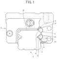
FIG. 1 is a cross-sectional view along a width direction, illustrating a configuration in a first embodiment of a linear motion guide device; -
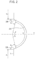
FIG. 2 is a cross-sectional view along the width direction, illustrating a configuration of a raceway surface in the first embodiment of the linear motion guide device; -
FIG. 3 is a cross-sectional view along the width direction, illustrating a processing step for a raceway surface of a slider in a first embodiment of a production method for a linear motion guide device; -
FIG. 4 is a cross-sectional view along the width direction, illustrating a grindstone molding step in the first embodiment of the production method for a linear motion guide device; -
FIG. 5A is a side view illustrating a configuration of a rotary dresser for use in the grindstone molding step in the first embodiment of the production method for a linear motion guide device; andFIG. 5B is a principal portion enlarged view ofFIG. 5A ; -
FIG. 6 is an enlarged view of a first processed portion ofFIG. 5B ; -
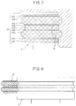
FIG. 7 is an enlarged view of a second processed portion ofFIG. 5B ; -
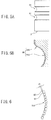
FIGS. 8A and 8B are views illustrating a fabrication method for the rotary dresser for use in the grindstone molding step in the first embodiment of the production method for a linear motion guide device; -
FIG. 9 is a front view illustrating a configuration of a grindstone in the first embodiment of the production method for a linear motion guide device; -
FIG. 10 is an enlarged view ofFIG. 9 ; -
FIG. 11A is an enlarged view of a first processed portion in a second embodiment of the production method for a linear motion guide device; andFIG. 11B is an enlarged view of a second processed portion in the second embodiment of the production method for a linear motion guide device; -
FIG. 12 is a side view illustrating a configuration of a grindstone in a third embodiment of the production method for a linear motion guide device; -
FIG. 13 is a side view illustrating a configuration of a grindstone in a fourth embodiment of the production method for a linear motion guide device; and -
FIG. 14 is a side view illustrating a modification example of the production method for a linear motion guide device. - In the following detailed description, many specific details are described so as to provide perfect understanding of embodiments of the present invention. However, it will be obvious that one or more embodiments can be embodied without such specific details. In addition, in order to simplify the drawings, well-known structures and devices are illustrated by simplified diagrams.
- A description is made below of embodiments of a linear motion guide device with reference to the drawings.
-
FIG. 1 is a cross-sectional view along a width direction, illustrating a configuration in a certain embodiment of the linear motion guide device. - As illustrated in
FIG. 1 , the linear motion guide device of this embodiment includes: a guide rail 1 that extends linearly in a longitudinal direction; and aslider 2 that straddles the guide rail 1. In the guide rail 1, attachment holes (not illustrated) for inserting therethrough bolts which penetrate the same guide rail 1 in a height direction from an upper surface la thereof to a lower surface thereof are drilled at a predetermined interval in the longitudinal direction. - On both side surfaces in a width direction of the guide rail 1, raceway surfaces 11 and 11 formed along the longitudinal direction are provided in two lines in the height direction. Moreover, on inner side surfaces in a width direction of the
slider 2, raceway surfaces 21 and 21 are provided in two lines in the height direction so as to be opposed to the raceway surfaces 11. - In the raceway surfaces 11 and the raceway surfaces 21, cross sections thereof in a width direction (direction perpendicular to the longitudinal direction and the height direction) form a substantially circular-arc groove shape. Then, a rolling
path 3 is composed of the raceway surfaces 11 and the raceway surfaces 21, which are installed opposite to each other. Into this rollingpath 3, a plurality of rolling elements (for example, steel balls) 4 are inserted so as to be freely rollable. The linear motion guide device of this embodiment is configured as described above, whereby theslider 2 is made relatively movable along the longitudinal direction of the guide rail 1 via the plurality of rollingelements 4. - Here, as illustrated in
FIG. 2 , each of the raceway surfaces 21 of theslider 2 is composed of: afirst raceway surface 21A extending along the longitudinal direction; and second raceway surfaces 21B and 21B defined on both sides of thisfirst raceway surface 21A. Note that, inFIG. 2 , in theraceway surface 21 ground in theslider 2, a region defined by thefirst raceway surface 21A is denoted by "A1", a region defined by the second raceway surfaces 21B is denoted by "A2", and an unground region is denoted by "A3". - Moreover, preferably, the region "A1" defined by the
first raceway surface 21A is formed as a region in which an angle β is 77° or less, the angle β being made along theraceway surface 21 while taking, as a reference, a reference surface H that bisects theraceway surface 21 along the width direction of the slider. - Moreover, surface roughness of the second raceway surfaces 21B is set rougher than surface roughness of the
first raceway surface 21A. For example, the surface roughness (center line average roughness) Ra1 of thefirst raceway surface 21A ranges approximately from 0.2 µm to 1.6 µm. Moreover, preferably, surface roughness (center line average roughness) Ra2 of the second raceway surfaces 21B ranges approximately from 1.5 to 3 times the surface roughness Ra1 of thefirst raceway surface 21A. - As described above, the
raceway surface 21 of theslider 2 is composed of thefirst raceway surface 21A and the second raceway surfaces 21B, and the surface roughness Ra2 of the second raceway surfaces 21B is set rougher than the surface roughness Ra1 of thefirst raceway surface 21A, whereby workability of the second raceway surfaces 21B is good, and the surface roughness of thefirst raceway surface 21A can keep an appropriate value. Hence, a linear motion guide device free from a performance decrease can be provided. - A description is made below of a production method for the linear motion guide device of this embodiment with reference to the drawings. The production method for the linear motion guide device of this embodiment includes: a surface processing step of implementing surface processing for a raceway surface extending along a longitudinal direction of a slider; and an assembly step.
- Then, the surface processing step is a step of performing the surface processing at one time by the same grindstone so that the raceway surface of at least one of the slider and the guide rail can be composed of the first raceway surface extending in the longitudinal direction and the second raceway surfaces extending on both sides in the longitudinal direction of the first raceway surface, and that the surface roughness Ra2 of the second raceway surfaces 21B can be rougher than the surface roughness Ra1 of the
first raceway surface 21A. - Moreover, the assembly step is a step of disposing a plurality of rolling elements in a rolling path for rolling elements, which is formed of the raceway surface of the slider and the raceway surface of the guide rail, which is provided opposite to the raceway surface of the slider, and assembling the guide rail and the slider with each other so that the slider can be movable with respect to the guide rail via these rolling elements.
- Note that the longitudinal direction of the slider is a direction parallel to a longitudinal direction of the guide rail in an event where the slider is assembled with the guide rail.
- As illustrated in
FIG. 3 , in this step, there is used agrindstone 8 in which a plurality ofgrindstone portions first raceway surface 21A and thesecond raceway surface 21B, are molded integrally with each other, and the raceway surfaces 21 and 21 of theslider 2 are subjected to grinding finish by moving thegrindstone portions grindstone portions 81 is composed of: first processedportions 81A; second processedportions 81B provided on upper and lower surfaces along a rotation axis of thegrindstone 8; and third processedportions 81C provided between the second processedportions FIG. 4 , thisgrindstone 8 is molded in such a manner that thegrindstone portions rotary dresser 9. - Here, as illustrated in
FIG. 5A , therotary dresser 9 has formingportions grindstone portions FIG. 5B , each of these formingportions 91 is composed of: afirst surface 91A that forms a shape of transferring thefirst raceway surface 21A and the second raceway surfaces 21B; andsecond surfaces 91B which form a shape of transferring the second raceway surfaces 21B. - Each of the forming
portions 91 thus composed is configured in such a manner thatabrasive grains 93 are arrayed with a desired shape on a surface thereof and are integrated with one another by a bond layer such as plating. As theabrasive grains 93, there are mentioned brown alumina, white alumina, pink alumina, pulverized alumina, artificial emery, alumina zirconia, black silicon carbide, green silicon carbide, diamond, and cubic boron nitride. As the diamond, there are mentioned natural diamond, single crystal diamond, and polycrystalline diamond. Among them, diamond, which is more excellent than others in heat resistance and abrasion resistance, is suitable as theabrasive grains 93. - Next, a description is made of the
first surface 91A, which is illustrated inFIG. 5B , with reference toFIG. 6 . As illustrated inFIG. 6 , a particle diameter of theabrasive grains 93 using diamond have variations. An average grain diameter of theabrasive grains 93 for which diamond is used ranges approximately from 50 µm to 300 µm. Then, on thefirst surface 91A, a protrusion amount d1 of theabrasive grains 93 using diamond ranges approximately from 20 µm to 200 µm. This protrusion amount d1 is a dimension of theabrasive grains 93 protruding from abond layer 92 of thefirst surface 91A. This protrusion amount d1 also has variations among theabrasive grains 93. Accordingly, in this embodiment, the protrusion amount of theabrasive grains 93 is defined by an average protrusion amount. - Next, a description is made of the
second surface 91B, which is illustrated inFIG. 5B , with reference toFIG. 7 . As illustrated inFIG. 7 , a protrusion amount d2 of theabrasive grains 93 on thesecond surface 91B for forming thesecond raceway surface 21B is set larger than the protrusion amount d1 of theabrasive grains 93 on thefirst surface 91A. This protrusion amount d2 is also a dimension of theabrasive grains 93 protruding from thebond layer 92 of thesecond surface 91B. Note that the average grain diameter of theabrasive grains 93 which compose thesecond surface 91B is substantially the same as the average grain diameter of theabrasive grains 93 which compose thefirst surface 91A. Meanwhile, preferably, the protrusion amount d2 of thesecond surface 91B ranges approximately from 1.5 to 3 times the protrusion amount d1 of thefirst surface 91A. - Next, a description is made of a production method for the rotary dresser with reference to
FIGS. 8A and 8B . As illustrated inFIG. 8A , therotary dresser 9 for forming the grindstone for use in this embodiment is fabricated by uniformly arraying the abrasive grains 93 (for example, diamond) on a surface of a base material. A protrusion amount d (= d1) of theabrasive grains 93 at this time ranges approximately from 20 µm to 200 µm on both of thefirst surface 91A and thesecond surface 91B (note that thesecond surface 91B is illustrated inFIG. 8A ). - Thereafter, as illustrated in
FIG. 8B ), the bond layer 92 (refer toFIG. 6 andFIG. 7 ) is dissolved only for thesecond surface 91B. In such a way, the protrusion amount of theabrasive grains 93 of thesecond surface 91B can be set larger than the protrusion amount of theabrasive grains 93 of thefirst surface 91A. Here, when the bond layer is dissolved too much, theabrasive grains 93 become prone to fall off. Moreover, when such dissolution of thebond layer 92 is insufficient, the protrusion amount of theabrasive grains 93 does not change very much between thefirst surface 91A and thesecond surface 91B. - In this connection, suitably, the protrusion amount d2 of the
abrasive grains 93 on thesecond surface 91B ranges approximately from 1.5 to 3 times the protrusion amount d1 of theabrasive grains 93 on thefirst surface 91A. - In this production method for the rotary dresser, the grain diameter of the
abrasive grains 93 which compose therotary dresser 9 is uniform everywhere. Therefore, there is an advantage that therotary dresser 9 can be fabricated relatively easily. - Next, a description is made of the grindstone molded by this
rotary dresser 9 with reference toFIG. 9 . The surface processing step in the production method for the linear motion guide device of this embodiment is a step of rotating thisgrindstone 8, allowing thegrindstone portions raceway surface 21 of theslider 2, and thereby grinding thefirst raceway surface 21A and thesecond raceway surface 21B. - Here, as illustrated in
FIG. 10 , in thegrindstone portion 81, with regard to the second processedportion 81B that grinds thesecond raceway surface 21B, a distance thereof from a rotation center of thegrindstone 8 is smaller in comparison with that of the first processedportion 81A that grinds thefirst raceway surface 21A. Hence, with regard to the second processedportion 81B that serves as a grindstone and grinds thesecond raceway surface 21B, a circumferential velocity thereof becomes smaller in comparison with that of the first processedportion 81A that grinds thefirst raceway surface 21A. Therefore, a grinding capability of the second processedportion 81B will be decreased in comparison with a grinding capability of the first processedportion 81A. - This difference of the grinding capability between the first processed
portion 81A and the second processedportion 81B sometimes requires a long time to perform the grinding, and sometimes causes an occurrence of degradation (tempering or the like) due to heat as a result of an increase of heat generation. - However, in this embodiment, as mentioned above, the protrusion amount d2 of the
abrasive grains 93 on thesecond surface 91B of therotary dresser 9 is set larger than the protrusion amount d1 of theabrasive grains 93 on thesecond surface 91B thereof. With regard to thegrindstone portion 81 of thegrindstone 8 molded by therotary dresser 9 designed as described above, the surface roughness of the first processedportion 81A is made smaller than the surface roughness of the second processedportion 81B. - Hence, in this embodiment, there is exerted such an effect that grindability of the second processed
portion 81B is enhanced to prevent a significant occurrence of the difference of the grinding capability between the first processedportion 81A and the second processedportion 81B. - As described above, with regard to the
grindstone 8 for use in this embodiment, thegrindstone portion 81 that grinds theraceway surface 21 of theslider 2 is composed of the first processedportion 81A and the second processedportion 81B, and the roughness of the second processedportion 81B is rougher in comparison with the roughness of the first processedportion 81A. That is to say, when the surface processing (grinding) is performed for theraceway surface 21 of theslider 2 by using thisgrindstone 8, the surface roughness of thesecond raceway surface 21B can be set rougher in comparison with the surface roughness of thefirst raceway surface 21A. Here, thesecond raceway surface 21B is processed by the second processedportion 81B in which the roughness is large in thegrindstone portion 81. The grindability is higher as the roughness of the grindstone portion is rougher. - Therefore, in accordance with this embodiment, a deterioration of the grindability on the
second raceway surface 21B can be prevented, and as a result, the time required for the grinding can be shortened, and the degradation due to the heat generation can also be prevented. - Note that, if the purpose is only to enhance the grinding capability of the
grindstone 8, then it is conceived to increase the roughness of both of the first processedportion 81A and the second processedportion 81B. - However, when the
grindstone 8 as described above is adopted, the roughness of the first processedportion 81A becomes rougher than an appropriate value, resulting in a possibility that abrasion and damage of thefirst raceway surface 21A may become prone to occur. - In this embodiment, the roughness of the
first raceway surface 21A can be kept appropriately, and accordingly, such a problem does not occur. - Next, a description is made of a second embodiment of the production method for the linear motion guide device with reference to the drawings. Note that this embodiment is different from the first embodiment only in a form of the rotary dresser that forms the
grindstone 8 for use in the surface processing step, and accordingly, a description of constituents, which are similar to those of the above-mentioned embodiment and are denoted by the same reference numerals as those thereof, is sometimes omitted. -
FIG. 11A is an enlarged view of a first surface of a rotary dresser in this embodiment, andFIG. 11B is an enlarged view of a second surface of the rotary dresser in this embodiment. As illustrated inFIGS. 11A and 11B , in this embodiment, not the protrusion amount of the abrasive grains 93 (for example, diamond) is changed between thefirst surface 91A and thesecond surface 91B, but the (average) grain diameter of theabrasive grains 93 may be changed between thefirst surface 91A and thesecond surface 91B. For example, preferably, the grain diameter of theabrasive grains 93 of thesecond surface 91B ranges approximately from 1.5 to 3 times the grain diameter of theabrasive grains 93 of thesecond surface 91B. - As described above, the grain diameter of the
abrasive grains 93 on thesecond surface 91B is set larger than the grain diameter of theabrasive grains 93 on thefirst surface 91A, whereby the protrusion amount of theabrasive grains 93 on thesecond surface 91B can be set larger than the protrusion amount of theabrasive grains 93 on thefirst surface 91A. Then, with regard to thegrindstone 8 molded by using therotary dresser 9 as described above, the roughness of the second processedportion 81B that grinds thesecond raceway portion 21B becomes rougher than the roughness of the first processedportion 81A. - Hence, in a similar way to the first embodiment, such a linear motion guide device can be fabricated, which includes the slider in which the surface roughness of the
second raceway portion 21B is rougher than the surface roughness of thefirst raceway portion 21A. - Next, a description is made of a third embodiment of the production method for the linear motion guide device with reference to the drawings. Note that this embodiment is different from the first embodiment only in a form of the
grindstone 8 for use in the surface processing step, and accordingly, a description of constituents, which are similar to those of the above-mentioned embodiment and are denoted by the same reference numerals as those thereof, is sometimes omitted. -
FIG. 12 is a side view illustrating a configuration of a grindstone in this embodiment. As illustrated inFIG. 12 , in this embodiment, the protrusion amount of the abrasive grains 93 (for example, diamond) in the rotary dresser (not illustrated) that molds thegrindstone 8 is made uniform, and granularity of thegrindstone portion 81 is made nonuniform. That is to say, thegrindstone 8 of this embodiment is composed in such a manner that the second processedportion 81B and the third processedportion 81C, which compose thegrindstone portion 81, are formed as a grindstone portion with small granularity, the first processedportion 81A is formed as a grindstone portion with large granularity, and both thereof are alternately sandwiched and integrated with each other. That is to say, the granularity of the second processedportion 81B and the third processedportion 81C, which grind thesecond raceway surface 21B of theslider 2 is smaller than the granularity of the first processedportion 81A. Note that, inFIG. 12 , with regard to the respective processed portion, such portions thereof composed with different grain diameters are illustrated with different types of hatching. - In this embodiment, the granularity of the grindstone ranges approximately from #30 to #400 in terms of mesh granularity. As the granularity is larger, the grain diameter is smaller. Moreover, preferably the granularity of the second processed
portion 81B and the third processedportion 81C ranges approximately from 0.2 to 0.8 times the granularity of the first processedportion 81A. - The surface processing step is performed by using this
grindstone 8, whereby the surface roughness of thesecond raceway surface 21B of theslider 2 of the linear motion guide device can be set rougher than the surface roughness of thefirst raceway surface 21A. - Next, a description is made of a fourth embodiment of the production method for the linear motion guide device with reference to the drawings. Note that this embodiment is also different from the third embodiment only in the form of the
grindstone 8 for use in the surface processing step, and accordingly, a description of constituents, which are similar to those of the above-mentioned embodiment and are denoted by the same reference numerals as those thereof, is sometimes omitted. -
FIG. 13 is a side view illustrating a configuration of a grindstone in this embodiment. As illustrated inFIG. 12 , in this embodiment, the protrusion amount of the abrasive grains 93 (for example, diamond) in the rotary dresser (not illustrated) that molds thegrindstone 8 is made uniform, and the granularity of thegrindstone portion 81 is made nonuniform. That is to say, thegrindstone 8 of this embodiment is composed in such a manner that, among the first processedportions 81A, the second processedportions 81B and the third processedportions 81C, which compose thegrindstone portion 81, the second processedportions 81B (81B') and the third processedportions 81C (81C'), which are located on upper and lower ends going along the rotation axis of thegrindstone 8, are formed as grindstone portions with small granularity, and the first processedportions 81A, the second processedportions 81B and the third processedportion 81C, which are sandwiched by these, are formed as grindstone portions with large granularity, and that these processed portions are integrated with each other. Note that, inFIG. 13 , with regard to the respective processed portion, such portions thereof composed with different grain diameters are illustrated with different types of hatching. - In this embodiment, it is easier to configure the grindstone in comparison with the above-mentioned third embodiment, and accordingly, the production cost of the
grindstone 8 can be reduced. - Here, as a modification example of the third embodiment, in addition to that the granularity of the grindstone is made nonuniform, the protrusion amount and grain diameter of the
abrasive grains 93 of therotary dresser 9 may be made nonuniform. In such a manner as described above, the grinding capability of the second processedportions 81B can be further enhanced. -
FIG. 14 is a side view illustrating a modification example of the production method for the linear motion guide device. In the above-mentioned embodiments, the surface processing (grinding) step for the raceway surfaces 21 of theslider 2 is mentioned; however, this may be applied to a surface processing (grinding) step for the raceway surfaces 11 of the guide rail 1. - Specifically, as illustrated in
FIG. 14 , there is used thegrindstone 8 in which the plurality ofgrindstone portions grindstone portions FIG. 4 , thisgrindstone 8 is molded in such a manner that thegrindstone portions rotary dresser 9. - As described above, also for the raceway surfaces 11 of the guide rail 1, similar effects to those in the above-mentioned case of implementing the surface processing step for the raceway surfaces 21 of the
slider 2 can be obtained. - The description is made above of the present invention with reference to the specific embodiments; however, it is not intended to limit the invention by the description of these. For those skilled in the art, other embodiments of the present invention are also obvious together with the variety of modification examples of the disclosed embodiments by referring to the description of the present invention. Hence, it should be understood that the scope of claims covers modification examples or embodiments of these included in the scope and spirit of the present invention.
-
- 1
- guide rail
- 2
- slider
- 21
- raceway surface
- 21A
- first raceway surface
- 21B
- second raceway surface
- 3
- rolling path
- 4
- rolling element
- 8
- grindstone
- 9
- rotary dresser
Claims (4)
- A linear motion guide device comprising a guide rail, a slider, and a plurality of rolling elements, wherein,
the guide rail and the slider individually have raceway surfaces, which form a rolling path of the rolling elements, at positions opposite to each other,
the raceway surfaces extend in a longitudinal direction of the guide rail,
the rolling elements are disposed in the rolling path,
and
the slider moves with respect to the guide rail via the rolling elements, and
the raceway surface of at least one of the slider and
the guide rail includes a first raceway surface extending in the longitudinal direction, and second raceway surfaces extending on both sides in the longitudinal direction of the first raceway surface, and surface roughness of the second raceway surfaces is set rougher than surface roughness of the first raceway surface. - The linear motion guide device according to claim 1, wherein center line average roughness of the second raceway surfaces is 1.5 to 3 times center line average roughness of the first raceway surface.
- A production method for a linear motion guide device comprising:a surface processing step of implementing surface processing for a raceway surface extending along a longitudinal direction of at least one of a slider and a guide rail; andan assembly step of disposing a plurality of rolling elements in a rolling path for rolling elements, which is formed of the raceway surface of the slider and the raceway surface of the guide rail, which is provided opposite to the raceway surface of the slider, and assembling the guide rail and the slider with each other so that the slider can be movable with respect to the guide rail via the rolling elements,wherein the surface processing step is a step of performing the surface processing at one time by a same grindstone so that the raceway surface of at least one of the slider and the guide rail includes a first raceway surface extending in the longitudinal direction, and a second raceway surface extending on both sides of the longitudinal direction of the first raceway surface, and that surface roughness of the second raceway surfaces is rougher than surface roughness of the first raceway surface.
- The production method for a linear motion guide device according to claim 3, the production method further comprising:a grindstone molding step of molding the grindstone by a rotary dresser,wherein a protrusion amount of abrasive grains or a grain diameter of the abrasive grains in regions of the rotary dresser, the regions corresponding to the second raceway surfaces, is made larger than a protrusion amount of the abrasive grains or a grain diameter of the abrasive grains in a region corresponding to the first raceway surface.
Applications Claiming Priority (2)
| Application Number | Priority Date | Filing Date | Title |
|---|---|---|---|
| JP2013249481A JP2015105742A (en) | 2013-12-02 | 2013-12-02 | Linear guide device, and manufacturing method thereof |
| PCT/JP2014/005917 WO2015083347A1 (en) | 2013-12-02 | 2014-11-26 | Linear motion guide device and production method therefor |
Publications (3)
| Publication Number | Publication Date |
|---|---|
| EP3059464A1 true EP3059464A1 (en) | 2016-08-24 |
| EP3059464A4 EP3059464A4 (en) | 2017-04-12 |
| EP3059464B1 EP3059464B1 (en) | 2018-11-21 |
Family
ID=53273132
Family Applications (1)
| Application Number | Title | Priority Date | Filing Date |
|---|---|---|---|
| EP14866828.8A Active EP3059464B1 (en) | 2013-12-02 | 2014-11-26 | Linear motion guide device and production method therefor |
Country Status (6)
| Country | Link |
|---|---|
| US (1) | US9765814B2 (en) |
| EP (1) | EP3059464B1 (en) |
| JP (1) | JP2015105742A (en) |
| CN (1) | CN105683599A (en) |
| TW (1) | TWI558924B (en) |
| WO (1) | WO2015083347A1 (en) |
Families Citing this family (3)
| Publication number | Priority date | Publication date | Assignee | Title |
|---|---|---|---|---|
| EP4296517A1 (en) | 2022-06-23 | 2023-12-27 | Sulzer Management AG | A pump unit for pumping liquid or suspension and a method for controlling of a pump unit |
| JP2025105080A (en) * | 2023-12-28 | 2025-07-10 | 日本精工株式会社 | Linear guide device and manufacturing method thereof |
| JP2025112938A (en) * | 2024-01-22 | 2025-08-01 | 日本精工株式会社 | Linear guide device and manufacturing method thereof |
Family Cites Families (23)
| Publication number | Priority date | Publication date | Assignee | Title |
|---|---|---|---|---|
| JPS5969521A (en) * | 1982-10-09 | 1984-04-19 | Hiroshi Teramachi | Simultaneously grinding type bearing body and endless sliding bearing unit built in |
| JPS63180437A (en) | 1987-01-19 | 1988-07-25 | Nippon Seiko Kk | Linear guide device |
| JPH023970U (en) * | 1988-06-17 | 1990-01-11 | ||
| JP2900527B2 (en) * | 1990-06-06 | 1999-06-02 | 日本精工株式会社 | Spherical roller bearing |
| JPH05220669A (en) * | 1992-02-07 | 1993-08-31 | O S G Kk | Composite grinding wheel |
| JPH08328376A (en) * | 1995-06-01 | 1996-12-13 | Canon Inc | Cylinder member for image forming apparatus and manufacturing method thereof |
| JP4298818B2 (en) * | 1998-08-18 | 2009-07-22 | Thk株式会社 | Linear rolling guide device |
| JP4586248B2 (en) * | 1999-12-08 | 2010-11-24 | 日本精工株式会社 | Processing method of linear motion guide rail |
| DE10005719A1 (en) * | 2000-02-09 | 2001-08-16 | Schaeffler Waelzlager Ohg | Linear roller bearings |
| JP2002130271A (en) | 2000-10-23 | 2002-05-09 | Nsk Ltd | Linear motion rolling guide device |
| US6520680B2 (en) * | 2000-07-13 | 2003-02-18 | Nsk Ltd. | Linear guide |
| JP4154931B2 (en) * | 2001-06-21 | 2008-09-24 | 日本精工株式会社 | Linear guide rail material, linear guide rail, linear guide rail manufacturing method, and linear guide |
| EP1310689B1 (en) * | 2001-11-13 | 2007-06-27 | NSK Ltd. | Linear guide bearing apparatus |
| JP2003148464A (en) * | 2001-11-13 | 2003-05-21 | Nsk Ltd | Linear guide device |
| JP2004316699A (en) * | 2003-04-11 | 2004-11-11 | Nsk Ltd | Linear motion guide bearing device |
| JP2005090615A (en) * | 2003-09-17 | 2005-04-07 | Nsk Ltd | Spherical roller bearing and method of processing the bearing |
| JP2006105197A (en) | 2004-10-01 | 2006-04-20 | Nsk Ltd | Linear guide device |
| US20100158420A1 (en) * | 2005-07-27 | 2010-06-24 | Thk Co., Ltd. | Method of manufacturing motion guide device and motion guide device manufactured by the method |
| JP2008175363A (en) * | 2007-01-22 | 2008-07-31 | Nsk Ltd | Linear guide |
| JP2009208179A (en) * | 2008-03-03 | 2009-09-17 | Canon Inc | Manufacturing method for elastic body roller |
| JP2013174339A (en) * | 2012-02-27 | 2013-09-05 | Seiko Instruments Inc | Rolling bearing, bearing device, information record reproducing device and method of manufacturing rolling bearing |
| DE112015002288B4 (en) * | 2014-05-15 | 2022-08-25 | The Timken Company | Bearing and method of forming a bearing |
| JP6365026B2 (en) * | 2014-07-03 | 2018-08-01 | 日本精工株式会社 | Linear motion guide device |
-
2013
- 2013-12-02 JP JP2013249481A patent/JP2015105742A/en active Pending
-
2014
- 2014-11-26 CN CN201480054287.4A patent/CN105683599A/en active Pending
- 2014-11-26 US US15/100,744 patent/US9765814B2/en active Active
- 2014-11-26 WO PCT/JP2014/005917 patent/WO2015083347A1/en not_active Ceased
- 2014-11-26 EP EP14866828.8A patent/EP3059464B1/en active Active
- 2014-12-02 TW TW103141796A patent/TWI558924B/en active
Also Published As
| Publication number | Publication date |
|---|---|
| CN105683599A (en) | 2016-06-15 |
| TWI558924B (en) | 2016-11-21 |
| JP2015105742A (en) | 2015-06-08 |
| WO2015083347A1 (en) | 2015-06-11 |
| EP3059464A4 (en) | 2017-04-12 |
| US9765814B2 (en) | 2017-09-19 |
| US20160305477A1 (en) | 2016-10-20 |
| EP3059464B1 (en) | 2018-11-21 |
| TW201537051A (en) | 2015-10-01 |
Similar Documents
| Publication | Publication Date | Title |
|---|---|---|
| US9127713B1 (en) | Bearing assemblies | |
| EP2351630B1 (en) | Apparatus for polishing spherical body, method for polishing spherical body and method for manufacturing spherical member | |
| CN102343551B (en) | Method and device for dressing a working layer of a double-sided grinding device | |
| US9816554B2 (en) | Systems including bearing assembly having enhanced selected support for nonuniform loads | |
| EP3059464B1 (en) | Linear motion guide device and production method therefor | |
| US9353791B1 (en) | Bearing assemblies, apparatuses, and motor assemblies using the same | |
| US9221149B2 (en) | Method for polishing semiconductor wafers by means of simultaneous double-side polishing | |
| US9453533B2 (en) | Roller bearing assemblies and apparatuses | |
| US20150204380A1 (en) | Bearing assemblies including a thermally conductive structure, bearing apparatuses, and methods of use | |
| KR20110015643A (en) | Processing method of slewing bearing and its raceway | |
| CN101247923A (en) | Tool having sintered body polishing part and method for manufacturing same | |
| KR101311346B1 (en) | A saw wire | |
| CN105729318A (en) | Grinding wheel for polishing and grinding ceramic tile biscuit, manufacturing method of grinding wheel and polishing and grinding apparatus and polishing and grinding method for ceramic tile biscuit | |
| KR20120122565A (en) | Cutting line and ingot cutting apparatus having the same | |
| US9333627B2 (en) | Grindstone tool and method for manufacturing same | |
| JP5254661B2 (en) | Rotating surface plate for double-sided lapping machine | |
| JP5567900B2 (en) | Electrodeposition whetstone and method for manufacturing the same | |
| CN105987156A (en) | Rack structure | |
| US9592584B2 (en) | Plate and dual side wafer grinding device including same | |
| CN119347649A (en) | Polishing pad conditioner, polishing pad and silicon wafer | |
| JP4326488B2 (en) | Segment chip manufacturing method and rotary grindstone |
Legal Events
| Date | Code | Title | Description |
|---|---|---|---|
| PUAI | Public reference made under article 153(3) epc to a published international application that has entered the european phase |
Free format text: ORIGINAL CODE: 0009012 |
|
| 17P | Request for examination filed |
Effective date: 20160518 |
|
| AK | Designated contracting states |
Kind code of ref document: A1 Designated state(s): AL AT BE BG CH CY CZ DE DK EE ES FI FR GB GR HR HU IE IS IT LI LT LU LV MC MK MT NL NO PL PT RO RS SE SI SK SM TR |
|
| AX | Request for extension of the european patent |
Extension state: BA ME |
|
| DAX | Request for extension of the european patent (deleted) | ||
| A4 | Supplementary search report drawn up and despatched |
Effective date: 20170310 |
|
| RIC1 | Information provided on ipc code assigned before grant |
Ipc: F16C 29/06 20060101AFI20170306BHEP |
|
| GRAP | Despatch of communication of intention to grant a patent |
Free format text: ORIGINAL CODE: EPIDOSNIGR1 |
|
| INTG | Intention to grant announced |
Effective date: 20180612 |
|
| GRAS | Grant fee paid |
Free format text: ORIGINAL CODE: EPIDOSNIGR3 |
|
| GRAA | (expected) grant |
Free format text: ORIGINAL CODE: 0009210 |
|
| AK | Designated contracting states |
Kind code of ref document: B1 Designated state(s): AL AT BE BG CH CY CZ DE DK EE ES FI FR GB GR HR HU IE IS IT LI LT LU LV MC MK MT NL NO PL PT RO RS SE SI SK SM TR |
|
| REG | Reference to a national code |
Ref country code: CH Ref legal event code: EP |
|
| REG | Reference to a national code |
Ref country code: IE Ref legal event code: FG4D |
|
| REG | Reference to a national code |
Ref country code: DE Ref legal event code: R096 Ref document number: 602014036696 Country of ref document: DE |
|
| REG | Reference to a national code |
Ref country code: AT Ref legal event code: REF Ref document number: 1067896 Country of ref document: AT Kind code of ref document: T Effective date: 20181215 |
|
| REG | Reference to a national code |
Ref country code: NL Ref legal event code: MP Effective date: 20181121 |
|
| REG | Reference to a national code |
Ref country code: AT Ref legal event code: MK05 Ref document number: 1067896 Country of ref document: AT Kind code of ref document: T Effective date: 20181121 |
|
| PG25 | Lapsed in a contracting state [announced via postgrant information from national office to epo] |
Ref country code: IS Free format text: LAPSE BECAUSE OF FAILURE TO SUBMIT A TRANSLATION OF THE DESCRIPTION OR TO PAY THE FEE WITHIN THE PRESCRIBED TIME-LIMIT Effective date: 20190321 Ref country code: LT Free format text: LAPSE BECAUSE OF FAILURE TO SUBMIT A TRANSLATION OF THE DESCRIPTION OR TO PAY THE FEE WITHIN THE PRESCRIBED TIME-LIMIT Effective date: 20181121 Ref country code: HR Free format text: LAPSE BECAUSE OF FAILURE TO SUBMIT A TRANSLATION OF THE DESCRIPTION OR TO PAY THE FEE WITHIN THE PRESCRIBED TIME-LIMIT Effective date: 20181121 Ref country code: ES Free format text: LAPSE BECAUSE OF FAILURE TO SUBMIT A TRANSLATION OF THE DESCRIPTION OR TO PAY THE FEE WITHIN THE PRESCRIBED TIME-LIMIT Effective date: 20181121 Ref country code: BG Free format text: LAPSE BECAUSE OF FAILURE TO SUBMIT A TRANSLATION OF THE DESCRIPTION OR TO PAY THE FEE WITHIN THE PRESCRIBED TIME-LIMIT Effective date: 20190221 Ref country code: AT Free format text: LAPSE BECAUSE OF FAILURE TO SUBMIT A TRANSLATION OF THE DESCRIPTION OR TO PAY THE FEE WITHIN THE PRESCRIBED TIME-LIMIT Effective date: 20181121 Ref country code: NO Free format text: LAPSE BECAUSE OF FAILURE TO SUBMIT A TRANSLATION OF THE DESCRIPTION OR TO PAY THE FEE WITHIN THE PRESCRIBED TIME-LIMIT Effective date: 20190221 Ref country code: LV Free format text: LAPSE BECAUSE OF FAILURE TO SUBMIT A TRANSLATION OF THE DESCRIPTION OR TO PAY THE FEE WITHIN THE PRESCRIBED TIME-LIMIT Effective date: 20181121 Ref country code: FI Free format text: LAPSE BECAUSE OF FAILURE TO SUBMIT A TRANSLATION OF THE DESCRIPTION OR TO PAY THE FEE WITHIN THE PRESCRIBED TIME-LIMIT Effective date: 20181121 |
|
| PG25 | Lapsed in a contracting state [announced via postgrant information from national office to epo] |
Ref country code: PT Free format text: LAPSE BECAUSE OF FAILURE TO SUBMIT A TRANSLATION OF THE DESCRIPTION OR TO PAY THE FEE WITHIN THE PRESCRIBED TIME-LIMIT Effective date: 20190321 Ref country code: AL Free format text: LAPSE BECAUSE OF FAILURE TO SUBMIT A TRANSLATION OF THE DESCRIPTION OR TO PAY THE FEE WITHIN THE PRESCRIBED TIME-LIMIT Effective date: 20181121 Ref country code: SE Free format text: LAPSE BECAUSE OF FAILURE TO SUBMIT A TRANSLATION OF THE DESCRIPTION OR TO PAY THE FEE WITHIN THE PRESCRIBED TIME-LIMIT Effective date: 20181121 Ref country code: RS Free format text: LAPSE BECAUSE OF FAILURE TO SUBMIT A TRANSLATION OF THE DESCRIPTION OR TO PAY THE FEE WITHIN THE PRESCRIBED TIME-LIMIT Effective date: 20181121 Ref country code: GR Free format text: LAPSE BECAUSE OF FAILURE TO SUBMIT A TRANSLATION OF THE DESCRIPTION OR TO PAY THE FEE WITHIN THE PRESCRIBED TIME-LIMIT Effective date: 20190222 Ref country code: NL Free format text: LAPSE BECAUSE OF FAILURE TO SUBMIT A TRANSLATION OF THE DESCRIPTION OR TO PAY THE FEE WITHIN THE PRESCRIBED TIME-LIMIT Effective date: 20181121 |
|
| REG | Reference to a national code |
Ref country code: CH Ref legal event code: PL |
|
| PG25 | Lapsed in a contracting state [announced via postgrant information from national office to epo] |
Ref country code: CZ Free format text: LAPSE BECAUSE OF FAILURE TO SUBMIT A TRANSLATION OF THE DESCRIPTION OR TO PAY THE FEE WITHIN THE PRESCRIBED TIME-LIMIT Effective date: 20181121 Ref country code: LU Free format text: LAPSE BECAUSE OF NON-PAYMENT OF DUE FEES Effective date: 20181126 Ref country code: IT Free format text: LAPSE BECAUSE OF FAILURE TO SUBMIT A TRANSLATION OF THE DESCRIPTION OR TO PAY THE FEE WITHIN THE PRESCRIBED TIME-LIMIT Effective date: 20181121 Ref country code: DK Free format text: LAPSE BECAUSE OF FAILURE TO SUBMIT A TRANSLATION OF THE DESCRIPTION OR TO PAY THE FEE WITHIN THE PRESCRIBED TIME-LIMIT Effective date: 20181121 Ref country code: PL Free format text: LAPSE BECAUSE OF FAILURE TO SUBMIT A TRANSLATION OF THE DESCRIPTION OR TO PAY THE FEE WITHIN THE PRESCRIBED TIME-LIMIT Effective date: 20181121 |
|
| REG | Reference to a national code |
Ref country code: BE Ref legal event code: MM Effective date: 20181130 |
|
| REG | Reference to a national code |
Ref country code: IE Ref legal event code: MM4A |
|
| REG | Reference to a national code |
Ref country code: DE Ref legal event code: R097 Ref document number: 602014036696 Country of ref document: DE |
|
| PG25 | Lapsed in a contracting state [announced via postgrant information from national office to epo] |
Ref country code: MC Free format text: LAPSE BECAUSE OF FAILURE TO SUBMIT A TRANSLATION OF THE DESCRIPTION OR TO PAY THE FEE WITHIN THE PRESCRIBED TIME-LIMIT Effective date: 20181121 Ref country code: CH Free format text: LAPSE BECAUSE OF NON-PAYMENT OF DUE FEES Effective date: 20181130 Ref country code: LI Free format text: LAPSE BECAUSE OF NON-PAYMENT OF DUE FEES Effective date: 20181130 Ref country code: RO Free format text: LAPSE BECAUSE OF FAILURE TO SUBMIT A TRANSLATION OF THE DESCRIPTION OR TO PAY THE FEE WITHIN THE PRESCRIBED TIME-LIMIT Effective date: 20181121 Ref country code: SK Free format text: LAPSE BECAUSE OF FAILURE TO SUBMIT A TRANSLATION OF THE DESCRIPTION OR TO PAY THE FEE WITHIN THE PRESCRIBED TIME-LIMIT Effective date: 20181121 Ref country code: SM Free format text: LAPSE BECAUSE OF FAILURE TO SUBMIT A TRANSLATION OF THE DESCRIPTION OR TO PAY THE FEE WITHIN THE PRESCRIBED TIME-LIMIT Effective date: 20181121 Ref country code: EE Free format text: LAPSE BECAUSE OF FAILURE TO SUBMIT A TRANSLATION OF THE DESCRIPTION OR TO PAY THE FEE WITHIN THE PRESCRIBED TIME-LIMIT Effective date: 20181121 |
|
| PLBE | No opposition filed within time limit |
Free format text: ORIGINAL CODE: 0009261 |
|
| STAA | Information on the status of an ep patent application or granted ep patent |
Free format text: STATUS: NO OPPOSITION FILED WITHIN TIME LIMIT |
|
| GBPC | Gb: european patent ceased through non-payment of renewal fee |
Effective date: 20190221 |
|
| 26N | No opposition filed |
Effective date: 20190822 |
|
| PG25 | Lapsed in a contracting state [announced via postgrant information from national office to epo] |
Ref country code: FR Free format text: LAPSE BECAUSE OF NON-PAYMENT OF DUE FEES Effective date: 20190121 Ref country code: SI Free format text: LAPSE BECAUSE OF FAILURE TO SUBMIT A TRANSLATION OF THE DESCRIPTION OR TO PAY THE FEE WITHIN THE PRESCRIBED TIME-LIMIT Effective date: 20181121 Ref country code: IE Free format text: LAPSE BECAUSE OF NON-PAYMENT OF DUE FEES Effective date: 20181126 |
|
| PG25 | Lapsed in a contracting state [announced via postgrant information from national office to epo] |
Ref country code: BE Free format text: LAPSE BECAUSE OF NON-PAYMENT OF DUE FEES Effective date: 20181130 |
|
| PG25 | Lapsed in a contracting state [announced via postgrant information from national office to epo] |
Ref country code: GB Free format text: LAPSE BECAUSE OF NON-PAYMENT OF DUE FEES Effective date: 20190221 Ref country code: MT Free format text: LAPSE BECAUSE OF NON-PAYMENT OF DUE FEES Effective date: 20181126 |
|
| PG25 | Lapsed in a contracting state [announced via postgrant information from national office to epo] |
Ref country code: TR Free format text: LAPSE BECAUSE OF FAILURE TO SUBMIT A TRANSLATION OF THE DESCRIPTION OR TO PAY THE FEE WITHIN THE PRESCRIBED TIME-LIMIT Effective date: 20181121 |
|
| PG25 | Lapsed in a contracting state [announced via postgrant information from national office to epo] |
Ref country code: HU Free format text: LAPSE BECAUSE OF FAILURE TO SUBMIT A TRANSLATION OF THE DESCRIPTION OR TO PAY THE FEE WITHIN THE PRESCRIBED TIME-LIMIT; INVALID AB INITIO Effective date: 20141126 Ref country code: CY Free format text: LAPSE BECAUSE OF FAILURE TO SUBMIT A TRANSLATION OF THE DESCRIPTION OR TO PAY THE FEE WITHIN THE PRESCRIBED TIME-LIMIT Effective date: 20181121 Ref country code: MK Free format text: LAPSE BECAUSE OF NON-PAYMENT OF DUE FEES Effective date: 20181121 |
|
| PGFP | Annual fee paid to national office [announced via postgrant information from national office to epo] |
Ref country code: DE Payment date: 20250930 Year of fee payment: 12 |