EP3059403A1 - Valve open/close period control device - Google Patents
Valve open/close period control device Download PDFInfo
- Publication number
- EP3059403A1 EP3059403A1 EP14853606.3A EP14853606A EP3059403A1 EP 3059403 A1 EP3059403 A1 EP 3059403A1 EP 14853606 A EP14853606 A EP 14853606A EP 3059403 A1 EP3059403 A1 EP 3059403A1
- Authority
- EP
- European Patent Office
- Prior art keywords
- intermediate lock
- phase
- rotating body
- channels
- working oil
- Prior art date
- Legal status (The legal status is an assumption and is not a legal conclusion. Google has not performed a legal analysis and makes no representation as to the accuracy of the status listed.)
- Granted
Links
- 239000012530 fluid Substances 0.000 claims abstract description 48
- 230000005611 electricity Effects 0.000 claims abstract description 44
- 230000007246 mechanism Effects 0.000 claims abstract description 32
- 238000002485 combustion reaction Methods 0.000 claims description 20
- 230000007423 decrease Effects 0.000 claims description 3
- 230000000979 retarding effect Effects 0.000 abstract description 49
- 230000009471 action Effects 0.000 abstract description 14
- 239000003921 oil Substances 0.000 description 96
- 230000004308 accommodation Effects 0.000 description 11
- 230000008859 change Effects 0.000 description 6
- 238000000034 method Methods 0.000 description 5
- 238000005192 partition Methods 0.000 description 4
- 230000008569 process Effects 0.000 description 4
- 230000003247 decreasing effect Effects 0.000 description 3
- 238000004891 communication Methods 0.000 description 2
- 238000010586 diagram Methods 0.000 description 2
- 230000000694 effects Effects 0.000 description 1
- 238000005516 engineering process Methods 0.000 description 1
- 239000010687 lubricating oil Substances 0.000 description 1
- 230000000149 penetrating effect Effects 0.000 description 1
Images



Classifications
-
- F—MECHANICAL ENGINEERING; LIGHTING; HEATING; WEAPONS; BLASTING
- F01—MACHINES OR ENGINES IN GENERAL; ENGINE PLANTS IN GENERAL; STEAM ENGINES
- F01L—CYCLICALLY OPERATING VALVES FOR MACHINES OR ENGINES
- F01L1/00—Valve-gear or valve arrangements, e.g. lift-valve gear
- F01L1/34—Valve-gear or valve arrangements, e.g. lift-valve gear characterised by the provision of means for changing the timing of the valves without changing the duration of opening and without affecting the magnitude of the valve lift
- F01L1/344—Valve-gear or valve arrangements, e.g. lift-valve gear characterised by the provision of means for changing the timing of the valves without changing the duration of opening and without affecting the magnitude of the valve lift changing the angular relationship between crankshaft and camshaft, e.g. using helicoidal gear
- F01L1/3442—Valve-gear or valve arrangements, e.g. lift-valve gear characterised by the provision of means for changing the timing of the valves without changing the duration of opening and without affecting the magnitude of the valve lift changing the angular relationship between crankshaft and camshaft, e.g. using helicoidal gear using hydraulic chambers with variable volume to transmit the rotating force
-
- F—MECHANICAL ENGINEERING; LIGHTING; HEATING; WEAPONS; BLASTING
- F01—MACHINES OR ENGINES IN GENERAL; ENGINE PLANTS IN GENERAL; STEAM ENGINES
- F01L—CYCLICALLY OPERATING VALVES FOR MACHINES OR ENGINES
- F01L1/00—Valve-gear or valve arrangements, e.g. lift-valve gear
- F01L1/34—Valve-gear or valve arrangements, e.g. lift-valve gear characterised by the provision of means for changing the timing of the valves without changing the duration of opening and without affecting the magnitude of the valve lift
- F01L1/344—Valve-gear or valve arrangements, e.g. lift-valve gear characterised by the provision of means for changing the timing of the valves without changing the duration of opening and without affecting the magnitude of the valve lift changing the angular relationship between crankshaft and camshaft, e.g. using helicoidal gear
- F01L1/3442—Valve-gear or valve arrangements, e.g. lift-valve gear characterised by the provision of means for changing the timing of the valves without changing the duration of opening and without affecting the magnitude of the valve lift changing the angular relationship between crankshaft and camshaft, e.g. using helicoidal gear using hydraulic chambers with variable volume to transmit the rotating force
- F01L2001/34423—Details relating to the hydraulic feeding circuit
- F01L2001/34426—Oil control valves
- F01L2001/3443—Solenoid driven oil control valves
-
- F—MECHANICAL ENGINEERING; LIGHTING; HEATING; WEAPONS; BLASTING
- F01—MACHINES OR ENGINES IN GENERAL; ENGINE PLANTS IN GENERAL; STEAM ENGINES
- F01L—CYCLICALLY OPERATING VALVES FOR MACHINES OR ENGINES
- F01L1/00—Valve-gear or valve arrangements, e.g. lift-valve gear
- F01L1/34—Valve-gear or valve arrangements, e.g. lift-valve gear characterised by the provision of means for changing the timing of the valves without changing the duration of opening and without affecting the magnitude of the valve lift
- F01L1/344—Valve-gear or valve arrangements, e.g. lift-valve gear characterised by the provision of means for changing the timing of the valves without changing the duration of opening and without affecting the magnitude of the valve lift changing the angular relationship between crankshaft and camshaft, e.g. using helicoidal gear
- F01L1/3442—Valve-gear or valve arrangements, e.g. lift-valve gear characterised by the provision of means for changing the timing of the valves without changing the duration of opening and without affecting the magnitude of the valve lift changing the angular relationship between crankshaft and camshaft, e.g. using helicoidal gear using hydraulic chambers with variable volume to transmit the rotating force
- F01L2001/34423—Details relating to the hydraulic feeding circuit
- F01L2001/34426—Oil control valves
- F01L2001/34433—Location oil control valves
-
- F—MECHANICAL ENGINEERING; LIGHTING; HEATING; WEAPONS; BLASTING
- F01—MACHINES OR ENGINES IN GENERAL; ENGINE PLANTS IN GENERAL; STEAM ENGINES
- F01L—CYCLICALLY OPERATING VALVES FOR MACHINES OR ENGINES
- F01L1/00—Valve-gear or valve arrangements, e.g. lift-valve gear
- F01L1/34—Valve-gear or valve arrangements, e.g. lift-valve gear characterised by the provision of means for changing the timing of the valves without changing the duration of opening and without affecting the magnitude of the valve lift
- F01L1/344—Valve-gear or valve arrangements, e.g. lift-valve gear characterised by the provision of means for changing the timing of the valves without changing the duration of opening and without affecting the magnitude of the valve lift changing the angular relationship between crankshaft and camshaft, e.g. using helicoidal gear
- F01L1/3442—Valve-gear or valve arrangements, e.g. lift-valve gear characterised by the provision of means for changing the timing of the valves without changing the duration of opening and without affecting the magnitude of the valve lift changing the angular relationship between crankshaft and camshaft, e.g. using helicoidal gear using hydraulic chambers with variable volume to transmit the rotating force
- F01L2001/3445—Details relating to the hydraulic means for changing the angular relationship
- F01L2001/34453—Locking means between driving and driven members
- F01L2001/34463—Locking position intermediate between most retarded and most advanced positions
-
- F—MECHANICAL ENGINEERING; LIGHTING; HEATING; WEAPONS; BLASTING
- F01—MACHINES OR ENGINES IN GENERAL; ENGINE PLANTS IN GENERAL; STEAM ENGINES
- F01L—CYCLICALLY OPERATING VALVES FOR MACHINES OR ENGINES
- F01L1/00—Valve-gear or valve arrangements, e.g. lift-valve gear
- F01L1/34—Valve-gear or valve arrangements, e.g. lift-valve gear characterised by the provision of means for changing the timing of the valves without changing the duration of opening and without affecting the magnitude of the valve lift
- F01L1/344—Valve-gear or valve arrangements, e.g. lift-valve gear characterised by the provision of means for changing the timing of the valves without changing the duration of opening and without affecting the magnitude of the valve lift changing the angular relationship between crankshaft and camshaft, e.g. using helicoidal gear
- F01L1/3442—Valve-gear or valve arrangements, e.g. lift-valve gear characterised by the provision of means for changing the timing of the valves without changing the duration of opening and without affecting the magnitude of the valve lift changing the angular relationship between crankshaft and camshaft, e.g. using helicoidal gear using hydraulic chambers with variable volume to transmit the rotating force
- F01L2001/3445—Details relating to the hydraulic means for changing the angular relationship
- F01L2001/34453—Locking means between driving and driven members
- F01L2001/34466—Locking means between driving and driven members with multiple locking devices
-
- F—MECHANICAL ENGINEERING; LIGHTING; HEATING; WEAPONS; BLASTING
- F01—MACHINES OR ENGINES IN GENERAL; ENGINE PLANTS IN GENERAL; STEAM ENGINES
- F01L—CYCLICALLY OPERATING VALVES FOR MACHINES OR ENGINES
- F01L1/00—Valve-gear or valve arrangements, e.g. lift-valve gear
- F01L1/34—Valve-gear or valve arrangements, e.g. lift-valve gear characterised by the provision of means for changing the timing of the valves without changing the duration of opening and without affecting the magnitude of the valve lift
- F01L1/344—Valve-gear or valve arrangements, e.g. lift-valve gear characterised by the provision of means for changing the timing of the valves without changing the duration of opening and without affecting the magnitude of the valve lift changing the angular relationship between crankshaft and camshaft, e.g. using helicoidal gear
- F01L1/3442—Valve-gear or valve arrangements, e.g. lift-valve gear characterised by the provision of means for changing the timing of the valves without changing the duration of opening and without affecting the magnitude of the valve lift changing the angular relationship between crankshaft and camshaft, e.g. using helicoidal gear using hydraulic chambers with variable volume to transmit the rotating force
- F01L2001/3445—Details relating to the hydraulic means for changing the angular relationship
- F01L2001/34453—Locking means between driving and driven members
- F01L2001/34473—Lock movement perpendicular to camshaft axis
-
- F—MECHANICAL ENGINEERING; LIGHTING; HEATING; WEAPONS; BLASTING
- F01—MACHINES OR ENGINES IN GENERAL; ENGINE PLANTS IN GENERAL; STEAM ENGINES
- F01L—CYCLICALLY OPERATING VALVES FOR MACHINES OR ENGINES
- F01L1/00—Valve-gear or valve arrangements, e.g. lift-valve gear
- F01L1/34—Valve-gear or valve arrangements, e.g. lift-valve gear characterised by the provision of means for changing the timing of the valves without changing the duration of opening and without affecting the magnitude of the valve lift
- F01L1/344—Valve-gear or valve arrangements, e.g. lift-valve gear characterised by the provision of means for changing the timing of the valves without changing the duration of opening and without affecting the magnitude of the valve lift changing the angular relationship between crankshaft and camshaft, e.g. using helicoidal gear
- F01L1/3442—Valve-gear or valve arrangements, e.g. lift-valve gear characterised by the provision of means for changing the timing of the valves without changing the duration of opening and without affecting the magnitude of the valve lift changing the angular relationship between crankshaft and camshaft, e.g. using helicoidal gear using hydraulic chambers with variable volume to transmit the rotating force
- F01L2001/3445—Details relating to the hydraulic means for changing the angular relationship
- F01L2001/34479—Sealing of phaser devices
Definitions
- the present invention relates to a valve open/close timing control device that controls a relative rotation phase of a driven rotating body with respect to a driving rotating body that rotates synchronously with a crankshaft of an internal combustion engine.
- valve open/close timing control devices that make it possible to change the opening/closing timing of an intake valve and an exhaust valve in accordance with the operation status of an internal combustion engine (hereinafter referred to as an "engine” as well) have been put to practical use.
- These valve open/close timing control devices have a mechanism that, for example, by changing the relative rotation phase of the driven rotating body with respect to the rotation of the driving rotating body (hereinafter referred to as simply “relative rotation phase”) by means of an engine operation, changes the opening/closing timing of an intake/exhaust valve that is opened and closed accompanying the rotation of the driven rotating body.
- the optimal opening/closing timing of the intake/exhaust valve differs according to the operation state of the engine, such as the state in which the engine is started, and the state in which the vehicle is traveling.
- the relative rotation phase By constraining the relative rotation phase to a predetermined phase between the maximum retard phase and the maximum advance phase when starting the engine, the opening/closing timing of the intake/exhaust valve that is optimal for starting the engine is realized, and a case in which a knocking sound is generated due to a partition of a fluid pressure chamber formed by the driving rotating body and the driven rotating body swinging is suppressed. For this reason, it is desired that the relative rotation phase is constrained to a predetermined phase before the engine is stopped.
- PTL 1 discloses a valve open/close timing control apparatus that can lock the relative rotation phase in an intermediate lock phase based on an engine stop signal.
- advancing control, retarding control, intermediate phase holding control, and lock control for locking in the intermediate lock phase are performed by one hydraulic control valve (electromagnetic valve). These controls are performed by changing the position of a spool in the hydraulic control valve according to an amount of electricity supplied to a solenoid.
- FIG. 21 of PTL 1 discloses a diagram showing an operation process of the hydraulic control valve, which is controlled such that "locking in an intermediate lock phase by means of a retarding action" is performed when the amount of electricity supplied to the solenoid is 0, and "locking in an intermediate lock phase by means of an advancing action” is performed when the amount of electricity supplied is the maximum.
- the operation process of the hydraulic control valve is merely illustrated in FIG. 21, and in paragraph [0067] of the specification in which FIG. 21 is described, there is no disclosure regarding the specific structure of the hydraulic control valve for realizing control of the operation process of the hydraulic control valve.
- the present invention aims to provide a valve open/close timing control device according to which it is possible to perform control for both "locking in an intermediate lock phase by means of a retarding action" and "locking in an intermediate lock phase by means of an advancing action" using one electromagnetic valve.
- a characteristic configuration of a valve open/close timing control device lies in including: a driving rotating body that rotates synchronously with a driving shaft of an internal combustion engine; a driven rotating body that is arranged inside of the driving rotating body, coaxially with an axis of the driving rotating body, and rotates integrally with a camshaft for opening/closing a valve of the internal combustion engine; a fluid pressure chamber defined between the driving rotating body and the driven rotating body; an intermediate lock mechanism capable of, with supply/discharge of a working fluid, selectively switching between a locked state in which a relative rotation phase of the driven rotating body with respect to the driving rotating body is constrained to an intermediate lock phase between a maximum advance phase and a maximum retard phase, and an unlocked state in which the constraint to the intermediate lock phase is released; an unlocking channel that allows passage of the working fluid to be supplied to or discharged from the intermediate lock mechanism; a lock discharge channel that does not allow passage of the working fluid to be supplied
- the unlocking channel allows the passage of the working fluid such that the working fluid is discharged to the outside.
- the cam average torque will be generated such that the relative rotation phase is more in the retard direction. Due to this fact, the relative rotation phase changes in the retard direction to the vicinity of the maximum retard phase.
- the locked state needs to be set by changing the relative rotation phase to the intermediate lock phase according to the cam variation torque, and in order to reliably set the locked state, the working fluid remaining in the intermediate lock mechanism needs to be discharged in a short amount of time.
- valve open/close timing control device when the electricity supply amount is 0, the working fluid flows through both the unlocking channel and the lock discharge channel and is discharged to the outside. Therefore, the cross-sectional area of the discharge channel at a time of re-starting the internal combustion engine can be increased in comparison to that of the conventional structure, and the working fluid can be discharged in a short amount of time. This makes it possible to reliably realize the locked state in the intermediate lock phase when re-starting the internal combustion engine. In particular, if the internal combustion engine is re-started in a low temperature such as -20°C, the working fluid will be more viscous and thus more difficult to discharge. Therefore, the structure of the valve open/close timing control device of the present invention, according to which the cross-sectional area of the discharge channel can be increased when the electricity supply amount is 0 is particularly desirable.
- valve open/close timing control device of the present invention it is preferable that when operation of the internal combustion engine is stopped in a case where the electricity supply amount to the electromagnetic valve is the maximum and the intermediate lock mechanism is in the locked state, the electricity supply amount changes from the maximum to 0 after fluid pressure of the working fluid acting on the intermediate lock mechanism decreases to be less than or equal to a fluid pressure at which the unlocked state is not switched to.
- a valve open/close timing control device 10 includes a housing 1 that rotates synchronously with a crankshaft C, and an inner rotor 2 that is disposed coaxially on axis X of the housing 1 inside of the housing 1 and rotates integrally with a camshaft 101 for opening/closing valves of the engine E.
- the camshaft 101 is a rotation shaft for cams 104, which control the opening/closing of intake valves 103 of the engine E, and rotates synchronously with the inner rotor 2 and a fixing bolt 5.
- the camshaft 101 is rotatably installed on a cylinder head of the engine E.
- the crankshaft C is an example of a driving shaft
- the housing 1 is an example of a driving rotating body
- the inner rotor 2 is an example of a driven rotating body.
- a male screw 5b is formed on an end near the camshaft 101 of the fixing bolt 5.
- the fixing bolt 5 is inserted into the middle and a male screw 5b of the fixing bolt 5 is screwed into a female screw 101 a of the camshaft 101, and thereby the fixing bolt 5 is fixed to the camshaft 101 and the inner rotor 2 and the camshaft 101 are also fixed.
- the housing 1 is constituted by installing, using a fastening bolt 16, a front plate 11 disposed on the side opposite to the side to which the camshaft 101 is connected, an outer rotor 12 fitted onto the inner rotor 2, and a rear plate 13 that integrally includes a timing sprocket 15 and is disposed on a side at which the camshaft 101 is connected.
- the inner rotor 2 is housed in the housing 1, and later-described fluid pressure chambers 4 are formed between the inner rotor 2 and the outer rotor 12.
- the inner rotor 2 and the outer rotor 12 are constituted so as to be able to rotate relative to each other about the axis X. Note that instead of the timing sprocket 15 being included in the rear plate 13, the timing sprocket 15 may be included in the outer circumferential portion of the outer rotor 12.
- a return spring 70 that causes a biasing force to act in a direction of rotation centered about the axis X is included between the housing 1 and the camshaft 101.
- the return spring 70 has a function of causing a biasing force to act until the relative rotation phase of the inner rotor 2 with respect to the housing 1 (hereinafter simply referred to as the "relative rotation phase") reaches a predetermined relative rotation phase that is on the advance side from the maximum retard state, and not causing the biasing force to act in a range in which the relative rotation phase is on the advance side of the predetermined rotation phase.
- a torsion spring or a spiral spring is used as the return spring 70.
- the return spring 70 may be disposed between the housing 1 and the inner rotor 2.
- the crankshaft C When the crankshaft C is driven so as to rotate, the rotation driving force is transferred to the timing sprocket 15 via a power transfer member 102, and the housing 1 is driven so as to rotate in a rotation direction S shown in FIG. 2 .
- the inner rotor 2 is driven so as to rotate in the rotation direction S so that the camshaft 101 rotates, and the cams 104 provided on the camshaft 101 press down the intake valves 103 of the engine E so as to open them.
- the fluid pressure chambers 4 are formed between the inner rotor 2 and the outer rotor 12 due to three protruding portions 14 that protrude inward in the radial direction and come into contact with the outer circumferential surface of the inner rotor 2 being formed apart from each other in the rotation direction S in the outer rotor 12.
- the protruding portions 14 also function as shoes on the outer circumferential surface of the inner rotor 2.
- Protruding portions 21 that come into contact with the inner circumferential surface of the outer rotor 12 are formed at portions on the outer circumferential surface of the inner rotor 2 which oppose the fluid pressure chambers 4.
- the fluid pressure chambers 4 are each divided into an advancing chamber 41 and a retarding chamber 42 by a protruding portion 21. Note that in the present embodiment, three fluid pressure chambers 4 are included, but there is no limitation to this.
- Working oil (an example of working fluid) is supplied to or discharged from the advancing chambers 41 and the retarding chambers 42, or the supply/discharge thereof is blocked, and thereby the oil pressure of the working oil acts on the protruding portions 21, the relative rotation phase is changed in the advance direction or the retard direction using the oil pressure, or is held at a certain phase.
- the advance direction is a direction in which the volume of the advancing chambers 41 increases, and is the direction indicated by arrow S1 in FIG. 2 .
- the retard direction is a direction in which the volume of the retarding chambers 42 increases, and is the direction indicated by arrow S2 in FIG. 2 .
- the relative rotation phase when the protruding portions 21 have reached their moving ends (ends of swinging centered about the axis X) in the advance direction S1 is referred to as the maximum advance phase
- the relative rotation phase when the protruding portions 21 have reached their moving ends (ends of swinging centered about the axis X) in the retard direction S2 is referred to as the maximum retard phase.
- the maximum advance phase is a concept that includes not only the moving ends in the advance direction S1 of the protruding portions 21, but also the vicinities thereof.
- the maximum retard phase is a concept that includes not only the moving ends in the retard direction S2 of the protruding portions 21, but also the vicinities thereof.
- advancing channels 43 that are in communication with the advancing chambers 41, retarding channels 44 that are in communication with the retarding chambers 42, unlocking channels 45 through which working oil that is to be supplied to and discharged from a later-described intermediate lock mechanism 8 flows, and lock discharge channels 46 through which working oil to be discharged from the intermediate lock mechanisms 8 to the outside of the valve open/close timing control device 10 flows are formed in the inner rotor 2.
- lubricating oil that is stored in an oil pan 61 of the engine E is used as the working oil, and the working oil is supplied to the advancing chambers 41, the retarding chambers 42, and the intermediate lock mechanism 8.
- the valve open/close timing control device 10 includes an intermediate lock mechanism 8 that constrains the relative rotation phase of the inner rotor 2 with respect to the housing 1 to an intermediate lock phase P between the maximum advance phase and the maximum retard phase by constraining change in the relative rotation phase. Due to the relative rotation phase being constrained to the intermediate lock phase P in a state where the oil pressure of the working oil immediately after the engine start operation is not stable, the rotation phase of the camshaft 101 with respect to the rotation phase of the crankshaft C is maintained appropriately, and stable rotation of the engine E can be realized.
- the intermediate lock mechanism 8 is constituted by a first lock member 81, a first spring 82, a second lock member 83, a second spring 84, a first recessed portion 85, and a second recessed portion 86.
- the first lock member 81 and the second lock member 83 are constituted by plate-shaped members, and are movably supported on the outer rotor 12 such that they can be brought toward and separated from the inner rotor 2 in an orientation parallel to the axis X.
- the first lock member 81 moves toward the inner rotor 2 due to the biasing force of the first spring 82
- the second lock member 83 moves toward the inner rotor 2 due to the biasing force of the second spring 84.
- the first recessed portion 85 is defined in a groove shape along the direction of the axis X in the outer circumference of the inner rotor 2.
- the first recessed portion 85 is such that a shallow groove and a deep groove are formed continuously in the circumferential direction toward the retard direction S2.
- the groove width of the shallow groove is larger than the thickness of the first lock member 81, and the groove width of the deep groove is equivalent to that of the shallow groove and is larger than the thickness of the first lock member 81.
- the second recessed portion 86 is defined in a groove shape along the direction of the axis X in the outer circumference of the inner rotor 2.
- the second recessed portion 86 is such that a shallow groove and a deep groove are formed continuously in the circumferential direction toward the retard direction S2.
- the groove width of the shallow groove is about the same as the thickness of the second lock member 83, and the groove width of the deep groove is sufficiently larger than the thickness of the second lock member 83 and is larger than the groove width of the deep groove of the
- the second lock member 83 fits into the second recessed portion 86 and the second lock member 83 comes into contact with the end in the retard direction S2 of the deep groove of the second recessed portion 86 so as to restrict the inner rotor 2 from changing in the advance direction S1.
- the relative rotation phase is constrained to the intermediate lock phase P by simultaneously restricting change in the advance direction S1 and the retard direction S2 of the inner rotor 2. This is the locked state.
- the unlocking channels 45 are connected to the bottom surfaces of the deep groove of the first recessed portion 85 and the deep groove of the second recessed portion 86, and when the working oil flows through the unlocking channels 45 so as to be supplied to the first recessed portion 85 and the second recessed portion 86 in the locked state, the first lock member 81 and the second lock member 83 receive the oil pressure of the working oil. If the oil pressure exceeds the biasing force of the first spring 82 and the second spring 84, the first lock member 81 and the second lock member 83 separate from the first recessed portion 85 and the second recessed portion 86 respectively, and the unlocked state is entered.
- the working oil which is in the first recessed portion 85 and the second recessed portion 86 in the unlocked state, flows through the unlocking channels 45 and can be discharged to the outside of the valve open/close timing control device 10.
- the unlocking channels 45 allow passage of working fluid that is to be supplied to or discharged from the first recessed portion 85 and the second recessed portion 86.
- the lock discharge channels 46 are also connected to the bottom surfaces of the deep groove of the first recessed portion 85 and the deep groove of the second recessed portion 86, but the lock discharge channels 46 do not allow passage of working oil that is to be supplied to the first recessed portion 85 and the second recessed portion 86, but allow passage of working oil that is to be discharged from the first recessed portion 85 and the second recessed portion 86 to the outside of the valve open/close timing control device 10.
- an OCV (oil control valve) 51 is disposed inside of the inner rotor 2, coaxially with the axis X.
- the OCV 51 is an example of an electromagnetic valve.
- the OCV 51 is configured to include a spool 52, a first spring 53a that biases the spool 52, and an electromagnetic solenoid 54 that drives the spool 52.
- the electromagnetic solenoid 54 is a known technology, and therefore will not be described in detail here.
- the spool 52 is accommodated in an accommodation space 5a, which is a hole with a circular cross-section that is formed in the direction of the axis X starting from a head portion 5c, which is the end that is further from the camshaft 101 of the fixing bolt 5, and the spool 52 can slide in the direction of the axis X inside of the accommodation space 5a.
- the spool 52 also has a main discharge channel 52b, which is a bottomed hole with a circular cross-section along the direction of the axis X.
- the inner diameter of the main discharge channel 52b is larger near the entrance than in the interior, and a level difference is formed therein.
- the first spring 53a is provided deep inside of the accommodation space 5a, and normally biases the spool 52 in the direction of the electromagnetic solenoid 54 (the leftward direction in FIG. 1 ).
- the spool 52 is prevented from popping out of the accommodation space 5a by a stopper 55 attached to the accommodation space 5a.
- the level difference formed in the main discharge channel 52b holds one end of the first spring 53a.
- a partition 5d is inserted at the border between the accommodation space 5a and a second through hole 47c, which is a bottomed hole with a smaller inner diameter and is formed continuously with the accommodation space 5a.
- the partition 5d holds the other end of the first spring 53a.
- the OCV 51 is configured to be able to adjust the position of the spool 52 by changing the amount of electricity supplied to the electromagnetic solenoid 54 from 0 to the maximum.
- the amount of electricity supplied to the electromagnetic solenoid 54 is controlled by an ECU (electronic control unit) (not shown).
- FIG. 3 shows an active configuration of the OCV 51 when the position of the spool 52 is changed to W1 to W5 according to the amount of electricity supplied to the electromagnetic solenoid 54.
- the working oil stored in the oil pan 61 is pumped by a mechanical oil pump 62 that is driven by the rotation driving force of the crankshaft C being transferred thereto, and the working oil flows through a later-described supply channel 47. Then, after flowing through the supply channel 47, the working oil is supplied to the advancing channels 43, the retarding channels 44, and the unlocking channels 45 via the OCV 51.
- the advancing channels 43 which are connected to the advancing chambers 41, are each constituted by a first through hole 43a formed in the fixing bolt 5 and a second through hole 43b that is connected to the first through hole 43a and is formed in the inner rotor 2.
- the retarding channels 44 which are connected to the retarding chambers 42, are each constituted by a first through hole 44a formed in the fixing bolt 5, and a second through hole 44b that is connected to the first through hole 44a and is formed in the inner rotor 2.
- the unlocking channels 45 which are connected to the first recessed portion 85 and the second recessed portion 86, are each constituted by a first through hole 45a formed in the fixing bolt 5, and a second through hole 45b that is connected to the first through hole 45a and is formed in the inner rotor 2.
- the lock discharge channels 46 which are connected to the first recessed portion 85 and the second recessed portion 86, are each constituted by a first through hole 46a formed in the fixing bolt 5, and a second through hole 46b that is connected to the first through hole 46a and is formed in the inner rotor 2.
- a supply channel 47 is constituted by a first through hole 47a formed in the camshaft 101, a first ring-shaped channel 47b, which is a space between the camshaft 101 and the fixing bolt 5, a second through hole 47c formed in the fixing bolt 5, a second ring-shaped channel 47d formed in the perimeter of the fixing bolt 5, a first channel 47e formed in the inner rotor 2, and third through holes 47f formed in the fixing bolt 5, and the channels are connected in the stated order.
- the second through hole 47c is constituted by a bottomed hole formed in the fixing bolt 5 in the direction of the axis X, and multiple holes penetrating to the outer circumference at two different locations in the axis X direction in the bottomed hole.
- a check valve 48 is included in an intermediate portion of the bottomed hole, and the check valve 48 is biased in the direction of closing the bottomed hole of the second through hole 47c by a second spring 53b, which is held by the partition 5d and the check valve 48.
- the first channel 47e is constituted by a channel that is formed in the fixing bolt 5 in the direction of the axis X and whose ends are closed, and three ring-shaped grooves formed inwardly in the radial direction from the channel to the inner circumferential surface at three different locations in the axis X direction.
- One of the three ring-shaped grooves opposes the second ring-shaped channel 47d, and the other two ring-shaped grooves oppose the third through holes 47f.
- the third through holes 47f are formed at two different locations along the direction of the axis X of the fixing bolt 5.
- a first ring-shaped groove 52c and a second ring-shaped groove 52d that supply the working oil that flows through the supply channel 47 to one of the advancing channels 43, the retarding channels 44, and the unlocking channels 45 are formed in the spool 52. Furthermore, a first through hole 52e and a second through hole 52f that discharge the working oil that flows through the advancing channels 43, the retarding channels 44, the unlocking channels 45, and the lock discharge channels 46 to the main discharge channel 52b are formed in the spool 52. Furthermore, third through holes 52g that discharge the working oil that flows through the main discharge channel 52b to the outside of the valve open/close timing control device 10 are formed.
- the OCV 51 is in the W1 state shown in FIG. 3 , and the spool 52 is in contact with the stopper 55 and is located leftmost due to the biasing force of the first spring 53a. If the working oil is supplied to the supply channel 47 in this state, the working oil flows through the first through hole 47a, the first ring-shaped channel 47b, and the second through hole 47c. If the oil pressure acting on the check valve 48 exceeds the biasing force of the second spring 53b in the second through hole 47c, the check valve 48 opens.
- the working oil flows through the second ring-shaped channel 47d, the first channel 47e, and the third through holes 47f so as to reach the first ring-shaped groove 52c and the second ring-shaped groove 52d.
- the first ring-shaped groove 52c is not connected to any of the channels, and thus no more working oil flows thereto.
- the second ring-shaped groove 52d is connected to the advancing channels 43, and therefore the working oil flows through the advancing channels 43 and is supplied to the advancing chambers 41. In other words, the advancing channels 43 are in a supply state.
- the retarding channels 44 are connected to the second through hole 52f
- the unlocking channels 45 are connected to the first through hole 52e
- the lock discharge channels 46 are connected to the accommodation space 5a, which is connected to the main discharge channel 52b.
- the working oil in the retarding chambers 42, the first recessed portion 85, and the second recessed portion 86 is discharged from the main discharge channel 52b to the outside of the valve open/close timing control device 10 through the third through holes 52g.
- the retarding channels 44, the unlocking channels 45, and the lock discharge channels 46 are all in the drain state.
- the inner rotor 2 changes in the advance direction S1
- the first lock member 81 fits into the first recessed portion 85
- the second lock member 83 fits into the second recessed portion 86
- the locked state is entered. This corresponds to "locking in an intermediate lock phase P by means of an advancing action”.
- cases in which "electricity is not supplied to the electromagnetic solenoid 54" include cases in which electricity is supplied to the electromagnetic solenoid 54 in a range in which the W1 state is maintained.
- the spool 52 moves slightly rightward from the W1 state. If the working oil is supplied to the supply channel 47 in this state, the working oil will reach the first ring-shaped groove 52c and the second ring-shaped groove 52d. Since the first ring-shaped groove 52c is connected to the unlocking channels 45, the working oil flows through the unlocking channels 45 and is supplied to the first recessed portion 85 and the second recessed portion 86. In other words, the unlocking channels 45 are in the supply state.
- the lock discharge channels 46 are not connected to the first through hole 52e, the second through hole 52f, or the accommodation space 5a, and thus a case does not occur in which the working oil flows through the lock discharge channels 46 to be discharged to the outside of the valve open/close timing control device 10. In other words, the lock discharge channels 46 are in the closed state. Accordingly, if the oil pressure of the working oil exceeds the biasing force of the first spring 82 and the second spring 84, the first lock member 81 and the second lock member 83 separate from the first recessed portion 85 and the second recessed portion 86 respectively, and the unlocked state is entered.
- the second ring-shaped groove 52d is still connected to the advancing channels 43, and therefore the working oil flows through the advancing channels 43 and is supplied to the advancing chambers 41. In other words, the advancing channels 43 are in the supply state.
- the retarding channels 44 are still connected to the second through hole 52f, the working oil in the retarding chambers 42 is discharged from the main discharge channel 52b to the outside of the valve open/close timing control device 10 through the third through holes 52g. In other words, the retarding channels 44 are in the drain state.
- the inner rotor 2 changes in the advance direction S1.
- the first recessed portion 85 and the second recessed portion 86 are filled with the working oil and are in the unlocked state, and therefore a case does not occur in which the locked state is entered even if the relative rotation phase reaches the intermediate lock phase P. This corresponds to "an advancing action in an unlocked state".
- the spool 52 moves slightly rightward from the W2 state. If the working oil is supplied to the supply channel 47 in this state, the working oil will reach the first ring-shaped groove 52c and the second ring-shaped groove 52d. Since the first ring-shaped groove 52c is still connected to the unlocking channels 45, the working oil flows through the unlocking channels 45 and is supplied to the first recessed portion 85 and the second recessed portion 86. In other words, the unlocking channels 45 are in the supply state.
- the lock discharge channels 46 are not connected to the first through hole 52e, the second through hole 52f, or the accommodation space 5a, and thus a case does not occur in which the working oil flows through the lock discharge channels 46 and is discharged to the outside of the valve open/close timing control device 10. In other words, the lock discharge channels 46 are in the closed state. Accordingly, if the oil pressure of the working oil exceeds the biasing force of the first spring 82 and the second spring 84, the first lock member 81 and the second lock member 83 separate from the first recessed portion 85 and the second recessed portion 86 respectively, and the unlocked state is entered.
- the second ring-shaped groove 52d is not connected to any of the channels, and thus no more working oil flows thereto.
- the working oil is not supplied to the advancing channels 43 or the retarding channels 44.
- the advancing channels 43 and the retarding channels 44 are not connected to the first through hole 52e or the second through hole 52f, and therefore a case does not occur in which the working oil in the advancing chambers 41 or the retarding chambers 42 is discharged to the outside of the valve open/close timing control device 10.
- the inner rotor 2 is held at the relative rotation phase as it is and does not change in the advance direction S1 or the retard direction S2.
- the advancing channels 43 and the retarding channels 44 are in the closed state, which corresponds to "intermediate phase holding".
- the spool 52 moves slightly rightward from the W3 state. If the working oil is supplied to the supply channel 47 in this state, the working oil will reach the first ring-shaped groove 52c and the second ring-shaped groove 52d. Since the first ring-shaped groove 52c is still connected to the unlocking channels 45, the working oil flows through the unlocking channels 45 and is supplied to the first recessed portion 85 and the second recessed portion 86. In other words, the unlocking channels 45 are in the supply state.
- the lock discharge channels 46 are not connected to the first through hole 52e, the second through hole 52f, or the accommodation space 5a, and thus a case does not occur in which the working oil flows through the lock discharge channels 46 so as to be discharged to the outside of the valve open/close timing control device 10.
- the lock discharge channels 46 are in the closed state. Accordingly, if the oil pressure of the working oil exceeds the biasing force of the first spring 82 and the second spring 84, the first lock member 81 and the second lock member 83 separate from the first recessed portion 85 and the second recessed portion 86 respectively, and the unlocked state is entered.
- the second ring-shaped groove 52d is connected to the retarding channels 44, and therefore the working oil flows through the retarding channels 44 and is supplied to the retarding chambers 42. In other words, the retarding channels 44 are in the supply state.
- the advancing channels 43 are connected to the first through hole 52e, the working oil in the advancing chambers 41 is discharged from the main discharge channel 52b to the outside of the valve open/close timing control device 10 through the third through holes 52g. In other words, the advancing channels 43 are in the drain state.
- the inner rotor 2 changes in the retard direction S2.
- the first recessed portion 85 and the second recessed portion 86 are filled with the working oil and are in the unlocked state, and therefore a case does not occur in which the locked state is entered even if the relative rotation phase reaches the intermediate lock phase P. This corresponds to "a retarding action in an unlocked state".
- the spool 52 moves slightly rightward from the W4 state. If the working oil is supplied to the supply channel 47 in this state, the working oil will reach the second ring-shaped groove 52d, but since the first ring-shaped groove 52c is not connected to the third through holes 47f, the working oil will not reach the first ring-shaped groove 52c.
- the second ring-shaped groove 52d is still connected to the retarding channels 44, and therefore the working oil flows through the retarding channels 44 and is supplied to the retarding chambers 42. In other words, the retarding channels 44 are in the supply state.
- the advancing channels 43 are connected to the first through holes 52e, and the lock discharge channels 46 are connected to the second through hole 52f.
- the working oil in the retarding chambers 42, the first recessed portion 85, and the second recessed portion 86 is discharged from the main discharge channel 52b to the outside of the valve open/close timing control device 10 through the third through holes 52g.
- the advancing channels 43 and the lock discharge channels 46 are both in the drain state.
- the lock discharge channels 45 are still connected to the first ring-shaped groove 52c, but as described above, since the first ring-shaped groove 52c is not connected to the third through holes 47f, no supply or discharge of the working oil is performed in the unlocking channels 45.
- the unlocking channels 45 are in the closed state. Note that since the lock discharge channels 46 are connected to the second through hole 52f, the working oil in the first recessed portion 85 and the second recessed portion 86 flows through the lock discharge channels 46 and is discharged to the outside of the valve open/close timing control device 10.
- valve open/close timing control device 10 having the above-described configuration, it is possible to perform setting to a locked state in the intermediate lock phase P by changing the inner rotor 2 in the advance direction S1 when the protruding portions 21 are in the retard direction S2 with respect to the intermediate lock phase P, and it is possible to perform setting to a locked state in the intermediate lock phase P by changing the inner rotor 2 in the retard direction S2 when the protruding portions 21 are in the advance direction S1 with respect to the intermediate lock phase P. Accordingly, it is possible to realize the locked state in the intermediate lock phase P in a short time, regardless of the positions of the protruding portions 21.
- both the unlocking channels 45 and the lock discharge channels 46 are connected to the bottom surfaces of the deep groove of the first recessed portion 85 and the deep groove of the second recessed portion 86. Also, in the W1 state, in which the electricity supply amount is 0, the working oil flows through both the unlocking channels 45 and the lock discharge channels 46 so as to be discharged to the outside of the valve open/close timing control apparatus 10, and therefore the working oil in the first recessed portion 85 and the second recessed portion 86 can be discharged in a shorter time compared to a conventional valve open/close timing control device 10 that includes only the unlocking channels 45. For this reason, it is possible to reliably realize the locked state in the intermediate lock phase P also by changing the relative rotation phase in a short amount of time.
- the cam average torque is generated such that the relative rotation phase moves in the retard direction S2. Due to this fact, the relative rotation phase changes in the retard direction S2 to the vicinity of the maximum retard phase. A case hardly ever occurs in which a change in the advance direction S1 is made and the intermediate lock phase P is reached.
- the locked state needs to be set by changing the relative rotation phase to the intermediate lock phase P according to the cam variation torque, and in order to reliably set the locked state, the working oil remaining in the first recessed portion 85 and the second recessed portion 86 needs to be discharged in a short amount of time.
- valve open/close timing control device 10 With the valve open/close timing control device 10, when the electricity supply amount is 0, the working oil flows through the first recessed portion 85 and the second recessed portion 86 so as to be discharged to the outside, and therefore the cross-sectional area of the discharge channel at the time of re-starting the engine E can be made larger compared to that of the conventional structure, and the working oil can be discharged in a short amount of time. This makes it possible to reliably realize the locked state in the intermediate lock phase P when re-starting the engine E. In particular, if the engine E is re-started in a low temperature such as -20°C, the working oil will be more viscous and thus more difficult to discharge. Therefore, the structure of the valve open/close timing control device 10 according to which the cross-sectional area of the discharge channel can be increased when the electricity supply amount is 0 is particularly desirable.
- the oil pressure of the working oil discharged from the oil pump 62 decreases and ultimately reaches 0. If the amount of electricity supplied to the electromagnetic solenoid 54 is set from the maximum to 0 at the same time as the ignition is turned off, the OCV 51 changes from the W5 state to the W1 state due to the biasing force of the first spring 53a.
- the working oil is supplied to the first recessed portion 85 and the second recessed portion 86 through the unlocking channels 45, and therefore if the oil pressure of the working oil discharged from the oil pump 62 has not decreased sufficiently, there is a risk that oil pressure exceeding the biasing forces of the first spring 82 and the second spring 84 will act on the first lock member 81 and the second lock member 83 and the unlocked state will be entered.
- the amount of electricity supplied to the electromagnetic solenoid 54 is set from the maximum to 0 not at the same time as the ignition is turned off, but after the oil pressure that will act on the first lock member 81 and the second lock member 83 has decreased to be less than or equal to the biasing force of the first spring 82 and the second spring 84.
- this kind of control makes it possible to maintain the locked state before the ignition is turned off, even after the ignition has been turned off, and it makes it possible to subsequently start the engine E in a state of being locked in the intermediate lock phase P, which is the relative rotation phase according to which the optimal intake/exhaust valve opening/closing timing is realized.
- the engine E can be started smoothly.
- any method such as detecting the oil pressure of the working oil using an oil pressure sensor, the elapse of a predetermined amount of time after the ignition is turned off, and the like, in determining that the oil pressure acting on the first lock member 81 and the second lock member 83 has decreased to be less than or equal to the biasing forces of the first spring 82 and the second spring 84.
- the second through hole 46b of the lock discharge channels 46 is connected to the second through hole 45b of the unlocking channels 45, and is not connected to the first recessed portion 85 and the second recessed portion 86.
- the dischargeability of the working oil at the time of re-starting the engine E after a stall can also be made equivalent by expanding the cross-sectional area of the second through hole 45b from the location at which the second through hole 46b is connected to the first recessed portion 85 and the second recessed portion 86 to a value greater than or equal to the sum of the cross-sectional area of the second through hole 45b before being connected to the second through hole 46b and the cross-sectional area of the second through hole 46b.
- the advancing channels 43 are in the supply state, and the retarding channels 44, unlocking channels 45, and lock discharge channels 46 are in the drain state, but there is no limitation to this structure.
- the retarding channels 44 are in the supply state, and the advancing channels 43, unlocking channels 45, and the lock discharge channels 46 are in the drain state when the electricity supply amount is 0.
- the working oil flows through both the first recessed portion 85 and the second recessed portion 86 and is discharged to the outside of the valve open/close timing control device 10 even if the engine E stalls when the protruding portions 21 are in the advance direction S1 with respect to the intermediate lock phase P. Therefore, the cross-sectional area of the discharge channels at the time of re-starting the engine E can be increased in comparison to that of the conventional structure, and the working oil can be discharged in a short amount of time.
- first lock member 81 and the second lock member 83 are both configured to move in the radial direction, but there is no limitation to this alone.
- the intermediate lock mechanism 8 may be configured such that the first lock member 81 and the second lock member 83 move in a direction along the axis X.
- the present invention can be used in a valve open/close timing control device that controls a relative rotation phase of a driven rotating body with respect to a driving rotating body that rotates synchronously with a crankshaft of an internal combustion engine.
Landscapes
- Engineering & Computer Science (AREA)
- Mechanical Engineering (AREA)
- General Engineering & Computer Science (AREA)
- Valve Device For Special Equipments (AREA)
Abstract
Description
- The present invention relates to a valve open/close timing control device that controls a relative rotation phase of a driven rotating body with respect to a driving rotating body that rotates synchronously with a crankshaft of an internal combustion engine.
- In recent years, valve open/close timing control devices that make it possible to change the opening/closing timing of an intake valve and an exhaust valve in accordance with the operation status of an internal combustion engine (hereinafter referred to as an "engine" as well) have been put to practical use. These valve open/close timing control devices have a mechanism that, for example, by changing the relative rotation phase of the driven rotating body with respect to the rotation of the driving rotating body (hereinafter referred to as simply "relative rotation phase") by means of an engine operation, changes the opening/closing timing of an intake/exhaust valve that is opened and closed accompanying the rotation of the driven rotating body.
- In general, the optimal opening/closing timing of the intake/exhaust valve differs according to the operation state of the engine, such as the state in which the engine is started, and the state in which the vehicle is traveling. By constraining the relative rotation phase to a predetermined phase between the maximum retard phase and the maximum advance phase when starting the engine, the opening/closing timing of the intake/exhaust valve that is optimal for starting the engine is realized, and a case in which a knocking sound is generated due to a partition of a fluid pressure chamber formed by the driving rotating body and the driven rotating body swinging is suppressed. For this reason, it is desired that the relative rotation phase is constrained to a predetermined phase before the engine is stopped.
-
PTL 1 discloses a valve open/close timing control apparatus that can lock the relative rotation phase in an intermediate lock phase based on an engine stop signal. In this valve open/close timing control apparatus, advancing control, retarding control, intermediate phase holding control, and lock control for locking in the intermediate lock phase are performed by one hydraulic control valve (electromagnetic valve). These controls are performed by changing the position of a spool in the hydraulic control valve according to an amount of electricity supplied to a solenoid. Specifically, (1) a case in which "total draining", "locking in an intermediate lock phase by means of an advancing action", "an advancing action in an unlocked state", "intermediate phase holding", and "a retarding action in an unlocked state" are controlled in the stated order, and (2) a case in which "a retarding action in an unlocked state", "intermediate phase holding", "an advancing action in an unlocked state", "locking in an intermediate lock phase by means of an advancing action", and "total draining" are controlled in the stated order, as the amount of electricity supplied to the solenoid increases from 0, are disclosed. - PTL 1:
JP 2003-172109A - In the control of (1) and (2) above of the valve open/close timing control device disclosed in
PTL 1, there is no state of "locking in an intermediate lock phase by means of a retarding action". For this reason, in order to perform locking in an intermediate lock phase with the relative rotation phase on the advance side of the intermediate lock phase, it has been necessary to perform locking using so-called loopback control in which control for "a retarding action in an unlocked state" is first performed so as to change the relative rotation phase to the retard side of the intermediate lock phase, and control for "locking in an intermediate lock phase by means of an advancing action" is switched to thereafter. For this reason, there has been a problem in that it takes a long time to achieve the locked state. - FIG. 21 of
PTL 1 discloses a diagram showing an operation process of the hydraulic control valve, which is controlled such that "locking in an intermediate lock phase by means of a retarding action" is performed when the amount of electricity supplied to the solenoid is 0, and "locking in an intermediate lock phase by means of an advancing action" is performed when the amount of electricity supplied is the maximum. However, the operation process of the hydraulic control valve is merely illustrated in FIG. 21, and in paragraph [0067] of the specification in which FIG. 21 is described, there is no disclosure regarding the specific structure of the hydraulic control valve for realizing control of the operation process of the hydraulic control valve. Also, regarding the hydraulic control valves disclosed in the other embodiments, there is no disclosure at all of a structure according to which control for both "locking in an intermediate lock phase by means of a retarding action" and "locking in an intermediate lock phase by means of an advancing action" is possible, and thus it has not been possible for a person skilled in the art to conceive of such a structure based on the disclosure. Accordingly, a structure according to which control for both "locking in an intermediate lock phase by means of a retarding action" and "locking in an intermediate lock phase by means of an advancing action" are possible using one hydraulic control valve cannot be carried out based onPTL 1, and thus there has been room to make further improvements to the valve open/close timing control device in order to realize such a structure. - In view of the above-described problems, the present invention aims to provide a valve open/close timing control device according to which it is possible to perform control for both "locking in an intermediate lock phase by means of a retarding action" and "locking in an intermediate lock phase by means of an advancing action" using one electromagnetic valve.
- In order to solve the above-described problem, a characteristic configuration of a valve open/close timing control device according to the present invention lies in including: a driving rotating body that rotates synchronously with a driving shaft of an internal combustion engine; a driven rotating body that is arranged inside of the driving rotating body, coaxially with an axis of the driving rotating body, and rotates integrally with a camshaft for opening/closing a valve of the internal combustion engine; a fluid pressure chamber defined between the driving rotating body and the driven rotating body; an intermediate lock mechanism capable of, with supply/discharge of a working fluid, selectively switching between a locked state in which a relative rotation phase of the driven rotating body with respect to the driving rotating body is constrained to an intermediate lock phase between a maximum advance phase and a maximum retard phase, and an unlocked state in which the constraint to the intermediate lock phase is released; an unlocking channel that allows passage of the working fluid to be supplied to or discharged from the intermediate lock mechanism; a lock discharge channel that does not allow passage of the working fluid to be supplied to the intermediate lock mechanism, but allows passage of the working fluid discharged from the intermediate lock mechanism to the outside; and an electromagnetic valve that is disposed inside of the driven rotating body, coaxially with the axis, and controls the supply and discharge of the working fluid to/from the fluid pressure chamber and the intermediate lock mechanism by changing an electricity supply amount, wherein if the electricity supply amount to the electromagnetic valve is 0 or the maximum, the lock discharge channel allows the passage of the working fluid such that the working fluid is discharged to the outside.
- With this kind of characteristic configuration, passage of the working fluid is allowed so that the working fluid is discharged from the intermediate lock mechanism to the outside when the electricity supply amount is 0 or the maximum, and therefore the intermediate lock mechanism enters a lockable state. Also, for example, by configuring the electromagnetic valve such that advancing control is performed when the electricity supply amount is 0 and retarding control is performed when the electricity supply amount is the maximum, it is possible to reach the intermediate lock phase directly without performing loopback control as with the valve open/close timing control device disclosed in
PTL 1, regardless of whether the relative rotation phase is on the retard side or the advance side of the intermediate lock phase. That is to say, it is possible to perform control for both "locking in an intermediate lock phase by means of a retarding action" and "locking in an intermediate lock phase by means of an advancing action". This makes it possible to realize the locked state in a short amount of time. - With the valve open/close timing control device of the present invention, it is preferable that if the electricity supply amount to the electromagnetic valve is 0, the unlocking channel allows the passage of the working fluid such that the working fluid is discharged to the outside.
- With this kind of configuration, if the electricity supply amount is 0, a state is entered in which the passage of the working fluid is allowed in both the unlocking channel and the lock discharge channel so that the working fluid is discharged to the outside. Accordingly, the working fluid can be discharged from the intermediate lock mechanism in a shorter time compared to a conventional valve open/close timing control device including only an unlocking channel. For this reason, it is possible to reliably realize the locked state in the intermediate lock phase also by changing the relative rotation phase of the driven rotating body with respect to the driving rotating body in a short amount of time.
- If the internal combustion engine stalls when the relative rotation phase of the driven rotating body with respect to the driving rotating body is in the retard direction with respect to the intermediate lock phase, the cam average torque will be generated such that the relative rotation phase is more in the retard direction. Due to this fact, the relative rotation phase changes in the retard direction to the vicinity of the maximum retard phase. Thus, if the internal combustion engine is re-started after being left alone in a state where the relative rotation phase is in the vicinity of the maximum retard phase, the locked state needs to be set by changing the relative rotation phase to the intermediate lock phase according to the cam variation torque, and in order to reliably set the locked state, the working fluid remaining in the intermediate lock mechanism needs to be discharged in a short amount of time. With the valve open/close timing control device according to the present invention, when the electricity supply amount is 0, the working fluid flows through both the unlocking channel and the lock discharge channel and is discharged to the outside. Therefore, the cross-sectional area of the discharge channel at a time of re-starting the internal combustion engine can be increased in comparison to that of the conventional structure, and the working fluid can be discharged in a short amount of time. This makes it possible to reliably realize the locked state in the intermediate lock phase when re-starting the internal combustion engine. In particular, if the internal combustion engine is re-started in a low temperature such as -20°C, the working fluid will be more viscous and thus more difficult to discharge. Therefore, the structure of the valve open/close timing control device of the present invention, according to which the cross-sectional area of the discharge channel can be increased when the electricity supply amount is 0 is particularly desirable.
- With the valve open/close timing control device of the present invention, it is preferable that when operation of the internal combustion engine is stopped in a case where the electricity supply amount to the electromagnetic valve is the maximum and the intermediate lock mechanism is in the locked state, the electricity supply amount changes from the maximum to 0 after fluid pressure of the working fluid acting on the intermediate lock mechanism decreases to be less than or equal to a fluid pressure at which the unlocked state is not switched to.
- If this kind of control is performed, it is possible to set the locked state by changing the relative rotation phase of the driven rotating body with respect to the driving rotating body to the intermediate lock phase before the operation of the internal combustion engine is stopped, and it is possible to keep the relative rotation phase at the intermediate lock phase without a switch to the unlocked state, even if the operation of the internal combustion engine is stopped thereafter. As a result, the internal combustion engine can be subsequently started in a state of being locked in the intermediate lock phase, which is a relative rotation phase that realizes the optimal opening/closing timing of the intake/exhaust valve, and the internal combustion engine can be started smoothly.
-
-
FIG. 1 is a vertical cross-sectional view showing a configuration of a valve open/close timing control device according to a first embodiment. -
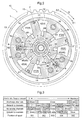
FIG. 2 is a cross-sectional view taken along line II-II inFIG. 1 . -
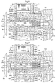
FIG. 3 is a diagram showing a state in which working oil flows through channels due to the action of an OCV. -
FIG. 4 is an enlarged cross-sectional view showing an active state of the OCV in W1. -
FIG. 5 is an enlarged cross-sectional view showing an active state of the OCV in W2. -
FIG. 6 is an enlarged cross-sectional view showing an active state of the OCV in W3. -
FIG. 7 is an enlarged cross-sectional view showing an active state of the OCV in W4. -
FIG. 8 is an enlarged cross-sectional view showing an active state of the OCV in W5. -
FIG. 9 is an enlarged cross-sectional view showing a configuration of a valve open/close timing control device according to a modified example of the first embodiment. - Hereinafter, a first embodiment in which the present invention is applied to a valve open/close timing control device for an intake valve in an automobile engine (hereinafter simply referred to as an "engine") E will be described in detail with reference to the drawings. In the following description of the embodiment, the engine E is an example of an internal combustion engine.
- As shown in
FIG. 1 , a valve open/closetiming control device 10 includes ahousing 1 that rotates synchronously with a crankshaft C, and aninner rotor 2 that is disposed coaxially on axis X of thehousing 1 inside of thehousing 1 and rotates integrally with acamshaft 101 for opening/closing valves of the engine E. Thecamshaft 101 is a rotation shaft forcams 104, which control the opening/closing ofintake valves 103 of the engine E, and rotates synchronously with theinner rotor 2 and afixing bolt 5. Thecamshaft 101 is rotatably installed on a cylinder head of the engine E. Note that the crankshaft C is an example of a driving shaft, thehousing 1 is an example of a driving rotating body, and theinner rotor 2 is an example of a driven rotating body. - A
male screw 5b is formed on an end near thecamshaft 101 of thefixing bolt 5. In a state in which thehousing 1 and theinner rotor 2 are combined, thefixing bolt 5 is inserted into the middle and amale screw 5b of thefixing bolt 5 is screwed into afemale screw 101 a of thecamshaft 101, and thereby thefixing bolt 5 is fixed to thecamshaft 101 and theinner rotor 2 and thecamshaft 101 are also fixed. - The
housing 1 is constituted by installing, using afastening bolt 16, afront plate 11 disposed on the side opposite to the side to which thecamshaft 101 is connected, anouter rotor 12 fitted onto theinner rotor 2, and arear plate 13 that integrally includes atiming sprocket 15 and is disposed on a side at which thecamshaft 101 is connected. Theinner rotor 2 is housed in thehousing 1, and later-describedfluid pressure chambers 4 are formed between theinner rotor 2 and theouter rotor 12. Theinner rotor 2 and theouter rotor 12 are constituted so as to be able to rotate relative to each other about the axis X. Note that instead of thetiming sprocket 15 being included in therear plate 13, thetiming sprocket 15 may be included in the outer circumferential portion of theouter rotor 12. - A
return spring 70 that causes a biasing force to act in a direction of rotation centered about the axis X is included between thehousing 1 and thecamshaft 101. Thereturn spring 70 has a function of causing a biasing force to act until the relative rotation phase of theinner rotor 2 with respect to the housing 1 (hereinafter simply referred to as the "relative rotation phase") reaches a predetermined relative rotation phase that is on the advance side from the maximum retard state, and not causing the biasing force to act in a range in which the relative rotation phase is on the advance side of the predetermined rotation phase. For example, a torsion spring or a spiral spring is used as thereturn spring 70. Note that thereturn spring 70 may be disposed between thehousing 1 and theinner rotor 2. - When the crankshaft C is driven so as to rotate, the rotation driving force is transferred to the
timing sprocket 15 via apower transfer member 102, and thehousing 1 is driven so as to rotate in a rotation direction S shown inFIG. 2 . Accompanying the rotation driving of thehousing 1, theinner rotor 2 is driven so as to rotate in the rotation direction S so that thecamshaft 101 rotates, and thecams 104 provided on thecamshaft 101 press down theintake valves 103 of the engine E so as to open them. - As shown in
FIG. 2 , thefluid pressure chambers 4 are formed between theinner rotor 2 and theouter rotor 12 due to three protrudingportions 14 that protrude inward in the radial direction and come into contact with the outer circumferential surface of theinner rotor 2 being formed apart from each other in the rotation direction S in theouter rotor 12. The protrudingportions 14 also function as shoes on the outer circumferential surface of theinner rotor 2. Protrudingportions 21 that come into contact with the inner circumferential surface of theouter rotor 12 are formed at portions on the outer circumferential surface of theinner rotor 2 which oppose thefluid pressure chambers 4. Thefluid pressure chambers 4 are each divided into an advancingchamber 41 and a retardingchamber 42 by a protrudingportion 21. Note that in the present embodiment, threefluid pressure chambers 4 are included, but there is no limitation to this. - Working oil (an example of working fluid) is supplied to or discharged from the advancing
chambers 41 and the retardingchambers 42, or the supply/discharge thereof is blocked, and thereby the oil pressure of the working oil acts on the protrudingportions 21, the relative rotation phase is changed in the advance direction or the retard direction using the oil pressure, or is held at a certain phase. The advance direction is a direction in which the volume of the advancingchambers 41 increases, and is the direction indicated by arrow S1 inFIG. 2 . The retard direction is a direction in which the volume of the retardingchambers 42 increases, and is the direction indicated by arrow S2 inFIG. 2 . The relative rotation phase when the protrudingportions 21 have reached their moving ends (ends of swinging centered about the axis X) in the advance direction S1 is referred to as the maximum advance phase, and the relative rotation phase when the protrudingportions 21 have reached their moving ends (ends of swinging centered about the axis X) in the retard direction S2 is referred to as the maximum retard phase. Note that the maximum advance phase is a concept that includes not only the moving ends in the advance direction S1 of the protrudingportions 21, but also the vicinities thereof. Similarly, the maximum retard phase is a concept that includes not only the moving ends in the retard direction S2 of the protrudingportions 21, but also the vicinities thereof. - As shown in
FIG. 2 , advancingchannels 43 that are in communication with the advancingchambers 41, retardingchannels 44 that are in communication with the retardingchambers 42, unlockingchannels 45 through which working oil that is to be supplied to and discharged from a later-describedintermediate lock mechanism 8 flows, and lockdischarge channels 46 through which working oil to be discharged from theintermediate lock mechanisms 8 to the outside of the valve open/closetiming control device 10 flows are formed in theinner rotor 2. As shown inFIG. 1 , in the valve open/closetiming control device 10, lubricating oil that is stored in anoil pan 61 of the engine E is used as the working oil, and the working oil is supplied to the advancingchambers 41, the retardingchambers 42, and theintermediate lock mechanism 8. - The valve open/close
timing control device 10 includes anintermediate lock mechanism 8 that constrains the relative rotation phase of theinner rotor 2 with respect to thehousing 1 to an intermediate lock phase P between the maximum advance phase and the maximum retard phase by constraining change in the relative rotation phase. Due to the relative rotation phase being constrained to the intermediate lock phase P in a state where the oil pressure of the working oil immediately after the engine start operation is not stable, the rotation phase of thecamshaft 101 with respect to the rotation phase of the crankshaft C is maintained appropriately, and stable rotation of the engine E can be realized. - As shown in
FIG. 2 , theintermediate lock mechanism 8 is constituted by afirst lock member 81, afirst spring 82, asecond lock member 83, asecond spring 84, a first recessedportion 85, and a second recessedportion 86. - The
first lock member 81 and thesecond lock member 83 are constituted by plate-shaped members, and are movably supported on theouter rotor 12 such that they can be brought toward and separated from theinner rotor 2 in an orientation parallel to the axis X. Thefirst lock member 81 moves toward theinner rotor 2 due to the biasing force of thefirst spring 82, and thesecond lock member 83 moves toward theinner rotor 2 due to the biasing force of thesecond spring 84. - The first recessed
portion 85 is defined in a groove shape along the direction of the axis X in the outer circumference of theinner rotor 2. The first recessedportion 85 is such that a shallow groove and a deep groove are formed continuously in the circumferential direction toward the retard direction S2. The groove width of the shallow groove is larger than the thickness of thefirst lock member 81, and the groove width of the deep groove is equivalent to that of the shallow groove and is larger than the thickness of thefirst lock member 81. The second recessedportion 86 is defined in a groove shape along the direction of the axis X in the outer circumference of theinner rotor 2. The second recessedportion 86 is such that a shallow groove and a deep groove are formed continuously in the circumferential direction toward the retard direction S2. The groove width of the shallow groove is about the same as the thickness of thesecond lock member 83, and the groove width of the deep groove is sufficiently larger than the thickness of thesecond lock member 83 and is larger than the groove width of the deep groove of the first recessedportion 85. - As shown in
FIG. 2 , with the intermediate lock phase P in a state in which there is no working oil in the first recessedportion 85 and the second recessedportion 86, after moving toward theinner rotor 2 due to the biasing force of thefirst spring 82, thefirst lock member 81 fits into the first recessedportion 85, and thefirst lock member 81 comes into contact with the end in the advance direction S1 of the deep groove of the first recessedportion 85 so as to restrict theinner rotor 2 from changing in the retard direction S2. Also, after moving toward theinner rotor 2 due to the biasing force of thesecond spring 84, thesecond lock member 83 fits into the second recessedportion 86 and thesecond lock member 83 comes into contact with the end in the retard direction S2 of the deep groove of the second recessedportion 86 so as to restrict theinner rotor 2 from changing in the advance direction S1. Thus, the relative rotation phase is constrained to the intermediate lock phase P by simultaneously restricting change in the advance direction S1 and the retard direction S2 of theinner rotor 2. This is the locked state. - The unlocking
channels 45 are connected to the bottom surfaces of the deep groove of the first recessedportion 85 and the deep groove of the second recessedportion 86, and when the working oil flows through the unlockingchannels 45 so as to be supplied to the first recessedportion 85 and the second recessedportion 86 in the locked state, thefirst lock member 81 and thesecond lock member 83 receive the oil pressure of the working oil. If the oil pressure exceeds the biasing force of thefirst spring 82 and thesecond spring 84, thefirst lock member 81 and thesecond lock member 83 separate from the first recessedportion 85 and the second recessedportion 86 respectively, and the unlocked state is entered. Also, the working oil, which is in the first recessedportion 85 and the second recessedportion 86 in the unlocked state, flows through the unlockingchannels 45 and can be discharged to the outside of the valve open/closetiming control device 10. Thus, the unlockingchannels 45 allow passage of working fluid that is to be supplied to or discharged from the first recessedportion 85 and the second recessedportion 86. - The
lock discharge channels 46 are also connected to the bottom surfaces of the deep groove of the first recessedportion 85 and the deep groove of the second recessedportion 86, but thelock discharge channels 46 do not allow passage of working oil that is to be supplied to the first recessedportion 85 and the second recessedportion 86, but allow passage of working oil that is to be discharged from the first recessedportion 85 and the second recessedportion 86 to the outside of the valve open/closetiming control device 10. - As shown in
FIG. 1 , in the present embodiment, an OCV (oil control valve) 51 is disposed inside of theinner rotor 2, coaxially with the axis X. TheOCV 51 is an example of an electromagnetic valve. TheOCV 51 is configured to include aspool 52, afirst spring 53a that biases thespool 52, and anelectromagnetic solenoid 54 that drives thespool 52. Note that theelectromagnetic solenoid 54 is a known technology, and therefore will not be described in detail here. - The
spool 52 is accommodated in anaccommodation space 5a, which is a hole with a circular cross-section that is formed in the direction of the axis X starting from ahead portion 5c, which is the end that is further from thecamshaft 101 of the fixingbolt 5, and thespool 52 can slide in the direction of the axis X inside of theaccommodation space 5a. Thespool 52 also has amain discharge channel 52b, which is a bottomed hole with a circular cross-section along the direction of the axis X. The inner diameter of themain discharge channel 52b is larger near the entrance than in the interior, and a level difference is formed therein. - The
first spring 53a is provided deep inside of theaccommodation space 5a, and normally biases thespool 52 in the direction of the electromagnetic solenoid 54 (the leftward direction inFIG. 1 ). Thespool 52 is prevented from popping out of theaccommodation space 5a by astopper 55 attached to theaccommodation space 5a. The level difference formed in themain discharge channel 52b holds one end of thefirst spring 53a. Apartition 5d is inserted at the border between theaccommodation space 5a and a second throughhole 47c, which is a bottomed hole with a smaller inner diameter and is formed continuously with theaccommodation space 5a. Thepartition 5d holds the other end of thefirst spring 53a. When electricity is supplied to theelectromagnetic solenoid 54, apush pin 54a provided in theelectromagnetic solenoid 54 presses theend 52a of thespool 52. As a result, thespool 52 slides in the direction of thecamshaft 101 against the biasing force of thefirst spring 53a. TheOCV 51 is configured to be able to adjust the position of thespool 52 by changing the amount of electricity supplied to theelectromagnetic solenoid 54 from 0 to the maximum. The amount of electricity supplied to theelectromagnetic solenoid 54 is controlled by an ECU (electronic control unit) (not shown). - According to the position of the
spool 52, theOCV 51 switches between the supply of working oil to the advancingchambers 41 and the retardingchambers 42, discharge thereof, and holding thereof, and performs switching between the supply of working oil to theintermediate lock mechanism 8 and the discharge thereof.FIG. 3 shows an active configuration of theOCV 51 when the position of thespool 52 is changed to W1 to W5 according to the amount of electricity supplied to theelectromagnetic solenoid 54. - As shown in
FIG. 1 , the working oil stored in theoil pan 61 is pumped by amechanical oil pump 62 that is driven by the rotation driving force of the crankshaft C being transferred thereto, and the working oil flows through a later-describedsupply channel 47. Then, after flowing through thesupply channel 47, the working oil is supplied to the advancingchannels 43, the retardingchannels 44, and the unlockingchannels 45 via theOCV 51. - As shown in
FIG. 1 andFIGS. 4 to 8 , the advancingchannels 43, which are connected to the advancingchambers 41, are each constituted by a first throughhole 43a formed in the fixingbolt 5 and a second throughhole 43b that is connected to the first throughhole 43a and is formed in theinner rotor 2. The retardingchannels 44, which are connected to the retardingchambers 42, are each constituted by a first throughhole 44a formed in the fixingbolt 5, and a second throughhole 44b that is connected to the first throughhole 44a and is formed in theinner rotor 2. The unlockingchannels 45, which are connected to the first recessedportion 85 and the second recessedportion 86, are each constituted by a first throughhole 45a formed in the fixingbolt 5, and a second throughhole 45b that is connected to the first throughhole 45a and is formed in theinner rotor 2. Thelock discharge channels 46, which are connected to the first recessedportion 85 and the second recessedportion 86, are each constituted by a first throughhole 46a formed in the fixingbolt 5, and a second throughhole 46b that is connected to the first throughhole 46a and is formed in theinner rotor 2. - A
supply channel 47 is constituted by a first throughhole 47a formed in thecamshaft 101, a first ring-shapedchannel 47b, which is a space between thecamshaft 101 and the fixingbolt 5, a second throughhole 47c formed in the fixingbolt 5, a second ring-shapedchannel 47d formed in the perimeter of the fixingbolt 5, afirst channel 47e formed in theinner rotor 2, and third throughholes 47f formed in the fixingbolt 5, and the channels are connected in the stated order. - The second through
hole 47c is constituted by a bottomed hole formed in the fixingbolt 5 in the direction of the axis X, and multiple holes penetrating to the outer circumference at two different locations in the axis X direction in the bottomed hole. Acheck valve 48 is included in an intermediate portion of the bottomed hole, and thecheck valve 48 is biased in the direction of closing the bottomed hole of the second throughhole 47c by asecond spring 53b, which is held by thepartition 5d and thecheck valve 48. - The
first channel 47e is constituted by a channel that is formed in the fixingbolt 5 in the direction of the axis X and whose ends are closed, and three ring-shaped grooves formed inwardly in the radial direction from the channel to the inner circumferential surface at three different locations in the axis X direction. One of the three ring-shaped grooves opposes the second ring-shapedchannel 47d, and the other two ring-shaped grooves oppose the third throughholes 47f. In other words, the third throughholes 47f are formed at two different locations along the direction of the axis X of the fixingbolt 5. - A first ring-shaped
groove 52c and a second ring-shapedgroove 52d that supply the working oil that flows through thesupply channel 47 to one of the advancingchannels 43, the retardingchannels 44, and the unlockingchannels 45 are formed in thespool 52. Furthermore, a first throughhole 52e and a second throughhole 52f that discharge the working oil that flows through the advancingchannels 43, the retardingchannels 44, the unlockingchannels 45, and thelock discharge channels 46 to themain discharge channel 52b are formed in thespool 52. Furthermore, third throughholes 52g that discharge the working oil that flows through themain discharge channel 52b to the outside of the valve open/closetiming control device 10 are formed. - As shown in
FIG. 4 , if electricity is not supplied to the electromagnetic solenoid 54 (electricity supply amount is 0), theOCV 51 is in the W1 state shown inFIG. 3 , and thespool 52 is in contact with thestopper 55 and is located leftmost due to the biasing force of thefirst spring 53a. If the working oil is supplied to thesupply channel 47 in this state, the working oil flows through the first throughhole 47a, the first ring-shapedchannel 47b, and the second throughhole 47c. If the oil pressure acting on thecheck valve 48 exceeds the biasing force of thesecond spring 53b in the second throughhole 47c, thecheck valve 48 opens. Then, the working oil flows through the second ring-shapedchannel 47d, thefirst channel 47e, and the third throughholes 47f so as to reach the first ring-shapedgroove 52c and the second ring-shapedgroove 52d. The first ring-shapedgroove 52c is not connected to any of the channels, and thus no more working oil flows thereto. The second ring-shapedgroove 52d is connected to the advancingchannels 43, and therefore the working oil flows through the advancingchannels 43 and is supplied to the advancingchambers 41. In other words, the advancingchannels 43 are in a supply state. On the other hand, the retardingchannels 44 are connected to the second throughhole 52f, the unlockingchannels 45 are connected to the first throughhole 52e, and thelock discharge channels 46 are connected to theaccommodation space 5a, which is connected to themain discharge channel 52b. For this reason, the working oil in the retardingchambers 42, the first recessedportion 85, and the second recessedportion 86 is discharged from themain discharge channel 52b to the outside of the valve open/closetiming control device 10 through the third throughholes 52g. In other words, the retardingchannels 44, the unlockingchannels 45, and thelock discharge channels 46 are all in the drain state. - If the
OCV 51 is controlled so as to be in the W1 state when the protrudingportions 21 are in the retard direction S2 with respect to the intermediate lock phase P, theinner rotor 2 changes in the advance direction S1, and when the relative rotation phase reaches the intermediate lock phase P, thefirst lock member 81 fits into the first recessedportion 85, thesecond lock member 83 fits into the second recessedportion 86, and the locked state is entered. This corresponds to "locking in an intermediate lock phase P by means of an advancing action". Note that cases in which "electricity is not supplied to theelectromagnetic solenoid 54" include cases in which electricity is supplied to theelectromagnetic solenoid 54 in a range in which the W1 state is maintained. - As shown in
FIG. 5 , if electricity is supplied to theelectromagnetic solenoid 54 so that theOCV 51 enters the W2 state shown inFIG. 3 , thespool 52 moves slightly rightward from the W1 state. If the working oil is supplied to thesupply channel 47 in this state, the working oil will reach the first ring-shapedgroove 52c and the second ring-shapedgroove 52d. Since the first ring-shapedgroove 52c is connected to the unlockingchannels 45, the working oil flows through the unlockingchannels 45 and is supplied to the first recessedportion 85 and the second recessedportion 86. In other words, the unlockingchannels 45 are in the supply state. At this time, thelock discharge channels 46 are not connected to the first throughhole 52e, the second throughhole 52f, or theaccommodation space 5a, and thus a case does not occur in which the working oil flows through thelock discharge channels 46 to be discharged to the outside of the valve open/closetiming control device 10. In other words, thelock discharge channels 46 are in the closed state. Accordingly, if the oil pressure of the working oil exceeds the biasing force of thefirst spring 82 and thesecond spring 84, thefirst lock member 81 and thesecond lock member 83 separate from the first recessedportion 85 and the second recessedportion 86 respectively, and the unlocked state is entered. - The second ring-shaped
groove 52d is still connected to the advancingchannels 43, and therefore the working oil flows through the advancingchannels 43 and is supplied to the advancingchambers 41. In other words, the advancingchannels 43 are in the supply state. On the other hand, since the retardingchannels 44 are still connected to the second throughhole 52f, the working oil in the retardingchambers 42 is discharged from themain discharge channel 52b to the outside of the valve open/closetiming control device 10 through the third throughholes 52g. In other words, the retardingchannels 44 are in the drain state. - If the
OCV 51 is controlled so as to be in the W2 state when the protrudingportions 21 are in the retard direction S2 with respect to the intermediate lock phase P, theinner rotor 2 changes in the advance direction S1. At this time, the first recessedportion 85 and the second recessedportion 86 are filled with the working oil and are in the unlocked state, and therefore a case does not occur in which the locked state is entered even if the relative rotation phase reaches the intermediate lock phase P. This corresponds to "an advancing action in an unlocked state". - As shown in
FIG. 6 , if electricity is further supplied to theelectromagnetic solenoid 54 so that theOCV 51 enters the W3 state shown inFIG. 3 , thespool 52 moves slightly rightward from the W2 state. If the working oil is supplied to thesupply channel 47 in this state, the working oil will reach the first ring-shapedgroove 52c and the second ring-shapedgroove 52d. Since the first ring-shapedgroove 52c is still connected to the unlockingchannels 45, the working oil flows through the unlockingchannels 45 and is supplied to the first recessedportion 85 and the second recessedportion 86. In other words, the unlockingchannels 45 are in the supply state. At this time, similarly to the time of being in the W2 state, thelock discharge channels 46 are not connected to the first throughhole 52e, the second throughhole 52f, or theaccommodation space 5a, and thus a case does not occur in which the working oil flows through thelock discharge channels 46 and is discharged to the outside of the valve open/closetiming control device 10. In other words, thelock discharge channels 46 are in the closed state. Accordingly, if the oil pressure of the working oil exceeds the biasing force of thefirst spring 82 and thesecond spring 84, thefirst lock member 81 and thesecond lock member 83 separate from the first recessedportion 85 and the second recessedportion 86 respectively, and the unlocked state is entered. - The second ring-shaped
groove 52d is not connected to any of the channels, and thus no more working oil flows thereto. In other words, the working oil is not supplied to the advancingchannels 43 or the retardingchannels 44. Also, the advancingchannels 43 and the retardingchannels 44 are not connected to the first throughhole 52e or the second throughhole 52f, and therefore a case does not occur in which the working oil in the advancingchambers 41 or the retardingchambers 42 is discharged to the outside of the valve open/closetiming control device 10. Accordingly, since supply and discharge of the working oil to/from the advancingchambers 41 and the retardingchambers 42 is not performed when theOCV 51 is controlled so as to be in the W3 state, theinner rotor 2 is held at the relative rotation phase as it is and does not change in the advance direction S1 or the retard direction S2. In other words, the advancingchannels 43 and the retardingchannels 44 are in the closed state, which corresponds to "intermediate phase holding". - As shown in
FIG. 7 , if electricity is further supplied to theelectromagnetic solenoid 54 so that theOCV 51 enters the W4 state shown inFIG. 3 , thespool 52 moves slightly rightward from the W3 state. If the working oil is supplied to thesupply channel 47 in this state, the working oil will reach the first ring-shapedgroove 52c and the second ring-shapedgroove 52d. Since the first ring-shapedgroove 52c is still connected to the unlockingchannels 45, the working oil flows through the unlockingchannels 45 and is supplied to the first recessedportion 85 and the second recessedportion 86. In other words, the unlockingchannels 45 are in the supply state. At this time, similarly to the cases of W2 and W3, thelock discharge channels 46 are not connected to the first throughhole 52e, the second throughhole 52f, or theaccommodation space 5a, and thus a case does not occur in which the working oil flows through thelock discharge channels 46 so as to be discharged to the outside of the valve open/closetiming control device 10. In other words, thelock discharge channels 46 are in the closed state. Accordingly, if the oil pressure of the working oil exceeds the biasing force of thefirst spring 82 and thesecond spring 84, thefirst lock member 81 and thesecond lock member 83 separate from the first recessedportion 85 and the second recessedportion 86 respectively, and the unlocked state is entered. - The second ring-shaped
groove 52d is connected to the retardingchannels 44, and therefore the working oil flows through the retardingchannels 44 and is supplied to the retardingchambers 42. In other words, the retardingchannels 44 are in the supply state. On the other hand, since the advancingchannels 43 are connected to the first throughhole 52e, the working oil in the advancingchambers 41 is discharged from themain discharge channel 52b to the outside of the valve open/closetiming control device 10 through the third throughholes 52g. In other words, the advancingchannels 43 are in the drain state. - If the
OCV 51 is controlled so as to be in the W4 state when the protrudingportions 21 are in the advance direction S1 with respect to the intermediate lock phase P, theinner rotor 2 changes in the retard direction S2. At this time, the first recessedportion 85 and the second recessedportion 86 are filled with the working oil and are in the unlocked state, and therefore a case does not occur in which the locked state is entered even if the relative rotation phase reaches the intermediate lock phase P. This corresponds to "a retarding action in an unlocked state". - As shown in
FIG. 8 , if the electricity supply amount to theelectromagnetic solenoid 54 is increased to its maximum so that theOCV 51 enters the W5 state shown inFIG. 3 , thespool 52 moves slightly rightward from the W4 state. If the working oil is supplied to thesupply channel 47 in this state, the working oil will reach the second ring-shapedgroove 52d, but since the first ring-shapedgroove 52c is not connected to the third throughholes 47f, the working oil will not reach the first ring-shapedgroove 52c. The second ring-shapedgroove 52d is still connected to the retardingchannels 44, and therefore the working oil flows through the retardingchannels 44 and is supplied to the retardingchambers 42. In other words, the retardingchannels 44 are in the supply state. On the other hand, the advancingchannels 43 are connected to the first throughholes 52e, and thelock discharge channels 46 are connected to the second throughhole 52f. For this reason, the working oil in the retardingchambers 42, the first recessedportion 85, and the second recessedportion 86 is discharged from themain discharge channel 52b to the outside of the valve open/closetiming control device 10 through the third throughholes 52g. In other words, the advancingchannels 43 and thelock discharge channels 46 are both in the drain state. Thelock discharge channels 45 are still connected to the first ring-shapedgroove 52c, but as described above, since the first ring-shapedgroove 52c is not connected to the third throughholes 47f, no supply or discharge of the working oil is performed in the unlockingchannels 45. In other words, the unlockingchannels 45 are in the closed state. Note that since thelock discharge channels 46 are connected to the second throughhole 52f, the working oil in the first recessedportion 85 and the second recessedportion 86 flows through thelock discharge channels 46 and is discharged to the outside of the valve open/closetiming control device 10. - If the
OCV 51 is controlled so as to be in the W5 state when the protrudingportions 21 are in the advance direction S1 with respect to the intermediate lock phase P, theinner rotor 2 changes in the retard direction S2, and when the relative rotation phase reaches the intermediate lock phase P, thefirst lock member 81 fits into the first recessedportion 85 and thesecond lock member 83 fits into the second recessedportion 86, and the locked state is entered. This corresponds to "locking in an intermediate lock phase P by means of a retarding action". Note that cases in which "the amount of electricity supplied to theelectromagnetic solenoid 54 is set to the maximum" include cases in which electricity is supplied with the electricity supply amount reduced from the maximum in a range in which the W5 state is maintained. - With the valve open/close
timing control device 10 having the above-described configuration, it is possible to perform setting to a locked state in the intermediate lock phase P by changing theinner rotor 2 in the advance direction S1 when the protrudingportions 21 are in the retard direction S2 with respect to the intermediate lock phase P, and it is possible to perform setting to a locked state in the intermediate lock phase P by changing theinner rotor 2 in the retard direction S2 when the protrudingportions 21 are in the advance direction S1 with respect to the intermediate lock phase P. Accordingly, it is possible to realize the locked state in the intermediate lock phase P in a short time, regardless of the positions of the protrudingportions 21. - In the present embodiment, both the unlocking
channels 45 and thelock discharge channels 46 are connected to the bottom surfaces of the deep groove of the first recessedportion 85 and the deep groove of the second recessedportion 86. Also, in the W1 state, in which the electricity supply amount is 0, the working oil flows through both the unlockingchannels 45 and thelock discharge channels 46 so as to be discharged to the outside of the valve open/closetiming control apparatus 10, and therefore the working oil in the first recessedportion 85 and the second recessedportion 86 can be discharged in a shorter time compared to a conventional valve open/closetiming control device 10 that includes only the unlockingchannels 45. For this reason, it is possible to reliably realize the locked state in the intermediate lock phase P also by changing the relative rotation phase in a short amount of time. - If the engine E stalls when the protruding
portions 21 are in the retard direction S2 with respect to the intermediate lock phase P, the cam average torque is generated such that the relative rotation phase moves in the retard direction S2. Due to this fact, the relative rotation phase changes in the retard direction S2 to the vicinity of the maximum retard phase. A case hardly ever occurs in which a change in the advance direction S1 is made and the intermediate lock phase P is reached. Thus, if the engine E is re-started after being left alone in a state where the relative rotation phase is near the maximum retard phase, the locked state needs to be set by changing the relative rotation phase to the intermediate lock phase P according to the cam variation torque, and in order to reliably set the locked state, the working oil remaining in the first recessedportion 85 and the second recessedportion 86 needs to be discharged in a short amount of time. With the valve open/closetiming control device 10, when the electricity supply amount is 0, the working oil flows through the first recessedportion 85 and the second recessedportion 86 so as to be discharged to the outside, and therefore the cross-sectional area of the discharge channel at the time of re-starting the engine E can be made larger compared to that of the conventional structure, and the working oil can be discharged in a short amount of time. This makes it possible to reliably realize the locked state in the intermediate lock phase P when re-starting the engine E. In particular, if the engine E is re-started in a low temperature such as -20°C, the working oil will be more viscous and thus more difficult to discharge. Therefore, the structure of the valve open/closetiming control device 10 according to which the cross-sectional area of the discharge channel can be increased when the electricity supply amount is 0 is particularly desirable. - In the present embodiment, if the ignition of the engine E is off when in the W5 state and the locked state in the intermediate lock phase P, the oil pressure of the working oil discharged from the
oil pump 62 decreases and ultimately reaches 0. If the amount of electricity supplied to theelectromagnetic solenoid 54 is set from the maximum to 0 at the same time as the ignition is turned off, theOCV 51 changes from the W5 state to the W1 state due to the biasing force of thefirst spring 53a. When in the W2, W3, and W4 states in the process of changing, the working oil is supplied to the first recessedportion 85 and the second recessedportion 86 through the unlockingchannels 45, and therefore if the oil pressure of the working oil discharged from theoil pump 62 has not decreased sufficiently, there is a risk that oil pressure exceeding the biasing forces of thefirst spring 82 and thesecond spring 84 will act on thefirst lock member 81 and thesecond lock member 83 and the unlocked state will be entered. - In order to avoid entering the unlocked state unintentionally, it is desirable that the amount of electricity supplied to the
electromagnetic solenoid 54 is set from the maximum to 0 not at the same time as the ignition is turned off, but after the oil pressure that will act on thefirst lock member 81 and thesecond lock member 83 has decreased to be less than or equal to the biasing force of thefirst spring 82 and thesecond spring 84. Performing this kind of control makes it possible to maintain the locked state before the ignition is turned off, even after the ignition has been turned off, and it makes it possible to subsequently start the engine E in a state of being locked in the intermediate lock phase P, which is the relative rotation phase according to which the optimal intake/exhaust valve opening/closing timing is realized. As a result, the engine E can be started smoothly. Note that it is possible to use any method, such as detecting the oil pressure of the working oil using an oil pressure sensor, the elapse of a predetermined amount of time after the ignition is turned off, and the like, in determining that the oil pressure acting on thefirst lock member 81 and thesecond lock member 83 has decreased to be less than or equal to the biasing forces of thefirst spring 82 and thesecond spring 84. - Next, a modified example of the first embodiment will be described with reference to the drawings. In the present modified example, the configuration of the
lock discharge channels 46 differs from the first embodiment, and the other configurations are the same. Accordingly, in the description of the present modified example, portions of the configuration that are the same as in the first embodiment are denoted by the same reference numerals, and description relating to similar configurations will not be repeated here. - As shown in
FIG. 9 , in the valve open/closetiming control device 10 according to the present modified example, the second throughhole 46b of thelock discharge channels 46 is connected to the second throughhole 45b of the unlockingchannels 45, and is not connected to the first recessedportion 85 and the second recessedportion 86. With this kind of configuration as well, it is possible to obtain an effect similar to that of the valve open/closetiming control device 10 of the first embodiment. In particular, the dischargeability of the working oil at the time of re-starting the engine E after a stall can also be made equivalent by expanding the cross-sectional area of the second throughhole 45b from the location at which the second throughhole 46b is connected to the first recessedportion 85 and the second recessedportion 86 to a value greater than or equal to the sum of the cross-sectional area of the second throughhole 45b before being connected to the second throughhole 46b and the cross-sectional area of the second throughhole 46b. - In the above-described embodiment and modified example, if the electricity supply amount is 0, the advancing
channels 43 are in the supply state, and the retardingchannels 44, unlockingchannels 45, and lockdischarge channels 46 are in the drain state, but there is no limitation to this structure. By reversing the arrangement of the advancingchannels 43 and the retardingchannels 44, it is possible to obtain a structure in which the retardingchannels 44 are in the supply state, and the advancingchannels 43, unlockingchannels 45, and thelock discharge channels 46 are in the drain state when the electricity supply amount is 0. By using this kind of configuration, when the electricity supply amount is 0, the working oil flows through both the first recessedportion 85 and the second recessedportion 86 and is discharged to the outside of the valve open/closetiming control device 10 even if the engine E stalls when the protrudingportions 21 are in the advance direction S1 with respect to the intermediate lock phase P. Therefore, the cross-sectional area of the discharge channels at the time of re-starting the engine E can be increased in comparison to that of the conventional structure, and the working oil can be discharged in a short amount of time. - In the above-described embodiment and modified example, the
first lock member 81 and thesecond lock member 83 are both configured to move in the radial direction, but there is no limitation to this alone. Theintermediate lock mechanism 8 may be configured such that thefirst lock member 81 and thesecond lock member 83 move in a direction along the axis X. - The present invention can be used in a valve open/close timing control device that controls a relative rotation phase of a driven rotating body with respect to a driving rotating body that rotates synchronously with a crankshaft of an internal combustion engine.
-
- 1
- Housing (driving rotating body)
- 2
- Inner rotor (driven rotating body)
- 4
- Fluid pressure chamber
- 8
- Intermediate lock mechanism
- 10
- Valve open/close timing control device
- 45
- Unlocking channel
- 46
- Lock discharge channel
- 51
- OCV (electromagnetic valve)
- 101
- Camshaft
- C
- Crankshaft (driving shaft)
- E
- Engine (internal combustion engine)
- P
- Intermediate lock phase
- X
- Axis
Claims (3)
- A valve open/close timing control device, comprising:a driving rotating body that rotates synchronously with a driving shaft of an internal combustion engine;a driven rotating body that is arranged inside of the driving rotating body, coaxially with an axis of the driving rotating body, and rotates integrally with a camshaft for opening/closing a valve of the internal combustion engine;a fluid pressure chamber defined between the driving rotating body and the driven rotating body;an intermediate lock mechanism capable of, with supply/discharge of a working fluid, selectively switching between a locked state in which a relative rotation phase of the driven rotating body with respect to the driving rotating body is constrained to an intermediate lock phase between a maximum advance phase and a maximum retard phase, and an unlocked state in which the constraint to the intermediate lock phase is released;an unlocking channel that allows passage of the working fluid to be supplied to or discharged from the intermediate lock mechanism;a lock discharge channel that does not allow passage of the working fluid to be supplied to the intermediate lock mechanism, but allows passage of the working fluid discharged from the intermediate lock mechanism to the outside; andan electromagnetic valve that is disposed inside of the driven rotating body, coaxially with the axis, and controls the supply and discharge of the working fluid to/from the fluid pressure chamber and the intermediate lock mechanism by changing an electricity supply amount,wherein if the electricity supply amount to the electromagnetic valve is 0 or the maximum, the lock discharge channel allows the passage of the working fluid such that the working fluid is discharged to the outside.
- The valve open/close timing control device according to claim 1, wherein
if the electricity supply amount to the electromagnetic valve is 0, the unlocking channel allows the passage of the working fluid such that the working fluid is discharged to the outside. - The valve open/close timing control device according to claim 1 or 2, wherein
when operation of the internal combustion engine is stopped in a case where the electricity supply amount to the electromagnetic valve is the maximum and the intermediate lock mechanism is in the locked state, the electricity supply amount changes from the maximum to 0 after fluid pressure of the working fluid acting on the intermediate lock mechanism decreases to be less than or equal to a fluid pressure at which the unlocked state is not switched to.
Applications Claiming Priority (2)
| Application Number | Priority Date | Filing Date | Title |
|---|---|---|---|
| JP2013215705A JP5979115B2 (en) | 2013-10-16 | 2013-10-16 | Valve timing control device |
| PCT/JP2014/076939 WO2015056617A1 (en) | 2013-10-16 | 2014-10-08 | Valve open/close period control device |
Publications (4)
| Publication Number | Publication Date |
|---|---|
| EP3059403A1 true EP3059403A1 (en) | 2016-08-24 |
| EP3059403A4 EP3059403A4 (en) | 2016-11-23 |
| EP3059403B1 EP3059403B1 (en) | 2018-03-28 |
| EP3059403B8 EP3059403B8 (en) | 2018-08-29 |
Family
ID=52828063
Family Applications (1)
| Application Number | Title | Priority Date | Filing Date |
|---|---|---|---|
| EP14853606.3A Not-in-force EP3059403B8 (en) | 2013-10-16 | 2014-10-08 | Valve open/close timing control device |
Country Status (5)
| Country | Link |
|---|---|
| US (1) | US9708939B2 (en) |
| EP (1) | EP3059403B8 (en) |
| JP (1) | JP5979115B2 (en) |
| CN (1) | CN105008679B (en) |
| WO (1) | WO2015056617A1 (en) |
Families Citing this family (9)
| Publication number | Priority date | Publication date | Assignee | Title |
|---|---|---|---|---|
| DE102012208812B4 (en) * | 2012-05-25 | 2018-02-01 | Schaeffler Technologies AG & Co. KG | Control valve of a camshaft adjuster |
| JP6264260B2 (en) | 2014-10-31 | 2018-01-24 | アイシン精機株式会社 | Valve timing control device |
| JP6528539B2 (en) * | 2015-05-27 | 2019-06-12 | アイシン精機株式会社 | Flow path partition structure and fluid control valve |
| JP6623768B2 (en) * | 2016-01-08 | 2019-12-25 | アイシン精機株式会社 | Valve timing control device |
| KR101689654B1 (en) * | 2016-02-05 | 2016-12-26 | 현대자동차주식회사 | Control valve for valve timing adjusting device of internal combustion engine |
| JP2018091225A (en) * | 2016-12-02 | 2018-06-14 | アイシン精機株式会社 | Valve timing control device |
| JP6809176B2 (en) | 2016-12-02 | 2021-01-06 | アイシン精機株式会社 | Valve opening / closing timing control device |
| JP6834658B2 (en) | 2017-03-23 | 2021-02-24 | アイシン精機株式会社 | Valve opening / closing timing control device |
| JP2019120230A (en) | 2018-01-10 | 2019-07-22 | アイシン精機株式会社 | Valve opening/closing timing control device |
Family Cites Families (17)
| Publication number | Priority date | Publication date | Assignee | Title |
|---|---|---|---|---|
| JP3783425B2 (en) | 1998-09-04 | 2006-06-07 | 三菱自動車工業株式会社 | Start control device for internal combustion engine |
| US6505586B1 (en) | 1999-08-05 | 2003-01-14 | Denso Corporation | Variable valve timing control apparatus and method for engines |
| JP3832730B2 (en) * | 2001-12-05 | 2006-10-11 | アイシン精機株式会社 | Valve timing control device |
| JP3867897B2 (en) | 2001-12-05 | 2007-01-17 | アイシン精機株式会社 | Valve timing control device |
| JP4161880B2 (en) * | 2003-11-12 | 2008-10-08 | トヨタ自動車株式会社 | Valve timing control device for internal combustion engine |
| JP5382427B2 (en) * | 2008-09-04 | 2014-01-08 | アイシン精機株式会社 | Valve timing control device |
| JP2010138698A (en) | 2008-12-09 | 2010-06-24 | Denso Corp | Variable valve timing control apparatus for internal combustion engine |
| JP4640510B2 (en) | 2009-01-14 | 2011-03-02 | 株式会社デンソー | Valve timing adjustment device |
| JP5267264B2 (en) * | 2009-03-25 | 2013-08-21 | アイシン精機株式会社 | Valve timing control device |
| WO2012077220A1 (en) * | 2010-12-09 | 2012-06-14 | トヨタ自動車 株式会社 | Variable valve gear for internal combustion engine |
| JP5360080B2 (en) | 2011-01-20 | 2013-12-04 | 株式会社デンソー | Valve timing adjustment device |
| JP5713823B2 (en) | 2011-07-08 | 2015-05-07 | 日立オートモティブシステムズ株式会社 | Control valve used in valve timing control device |
| JP5994297B2 (en) * | 2012-03-08 | 2016-09-21 | アイシン精機株式会社 | Valve timing control device |
| JP2013256929A (en) | 2012-06-14 | 2013-12-26 | Aisin Seiki Co Ltd | Valve open/close timing controller |
| JP2014034914A (en) | 2012-08-08 | 2014-02-24 | Aisin Seiki Co Ltd | Valve opening/closing time control device |
| JP6229564B2 (en) | 2014-03-19 | 2017-11-15 | アイシン精機株式会社 | Valve timing control device |
| JP6079676B2 (en) | 2014-03-26 | 2017-02-15 | アイシン精機株式会社 | Valve timing control device |
-
2013
- 2013-10-16 JP JP2013215705A patent/JP5979115B2/en not_active Expired - Fee Related
-
2014
- 2014-10-08 US US14/772,164 patent/US9708939B2/en not_active Expired - Fee Related
- 2014-10-08 WO PCT/JP2014/076939 patent/WO2015056617A1/en not_active Ceased
- 2014-10-08 CN CN201480011329.6A patent/CN105008679B/en not_active Expired - Fee Related
- 2014-10-08 EP EP14853606.3A patent/EP3059403B8/en not_active Not-in-force
Also Published As
| Publication number | Publication date |
|---|---|
| EP3059403A4 (en) | 2016-11-23 |
| CN105008679B (en) | 2017-09-22 |
| US9708939B2 (en) | 2017-07-18 |
| EP3059403B1 (en) | 2018-03-28 |
| JP2015078635A (en) | 2015-04-23 |
| US20160298504A1 (en) | 2016-10-13 |
| WO2015056617A1 (en) | 2015-04-23 |
| EP3059403B8 (en) | 2018-08-29 |
| JP5979115B2 (en) | 2016-08-24 |
| CN105008679A (en) | 2015-10-28 |
Similar Documents
| Publication | Publication Date | Title |
|---|---|---|
| EP3059403B1 (en) | Valve open/close timing control device | |
| JP5582363B2 (en) | Valve timing control device | |
| JP5403341B2 (en) | Valve timing control device | |
| JP5873339B2 (en) | Valve timing control device for internal combustion engine | |
| CN103375212B (en) | The variable valve gear of internal combustion engine | |
| JP2012057578A (en) | Valve timing control device | |
| US20180266283A1 (en) | Variable camshaft timing mechanism with a lock pin engaged by oil pressure | |
| JP2012097594A (en) | Valve timing control device of internal combustion engine | |
| JP2013002373A (en) | Valve timing control device of internal combustion engine | |
| JP2010270740A (en) | Valve timing control device | |
| EP2990620B1 (en) | Valve timing control apparatus | |
| EP2899377A1 (en) | Variable valve timing control device | |
| EP3214279B1 (en) | Valve-opening-closing-timing control device | |
| JP2004360606A (en) | Valve timing adjustment device | |
| EP3029286B1 (en) | Valve opening/closing timing control device | |
| CN103485853B (en) | The variable valve gear of internal combustion engine | |
| US9410454B2 (en) | Valve opening/closing timing control device | |
| EP2806119B1 (en) | Valve opening/closing timing control device | |
| US10107151B2 (en) | Control valve | |
| WO2015029476A1 (en) | Device for controlling valve opening and closing timing | |
| JP5793107B2 (en) | Variable valve operating device for internal combustion engine | |
| JP6150217B2 (en) | Control valve | |
| JP2010019146A (en) | Valve opening/closing timing control device |
Legal Events
| Date | Code | Title | Description |
|---|---|---|---|
| PUAI | Public reference made under article 153(3) epc to a published international application that has entered the european phase |
Free format text: ORIGINAL CODE: 0009012 |
|
| 17P | Request for examination filed |
Effective date: 20150828 |
|
| AK | Designated contracting states |
Kind code of ref document: A1 Designated state(s): AL AT BE BG CH CY CZ DE DK EE ES FI FR GB GR HR HU IE IS IT LI LT LU LV MC MK MT NL NO PL PT RO RS SE SI SK SM TR |
|
| AX | Request for extension of the european patent |
Extension state: BA ME |
|
| A4 | Supplementary search report drawn up and despatched |
Effective date: 20161024 |
|
| RIC1 | Information provided on ipc code assigned before grant |
Ipc: F01L 1/356 20060101AFI20161018BHEP |
|
| DAX | Request for extension of the european patent (deleted) | ||
| 17Q | First examination report despatched |
Effective date: 20170622 |
|
| GRAP | Despatch of communication of intention to grant a patent |
Free format text: ORIGINAL CODE: EPIDOSNIGR1 |
|
| INTG | Intention to grant announced |
Effective date: 20171013 |
|
| GRAS | Grant fee paid |
Free format text: ORIGINAL CODE: EPIDOSNIGR3 |
|
| GRAA | (expected) grant |
Free format text: ORIGINAL CODE: 0009210 |
|
| AK | Designated contracting states |
Kind code of ref document: B1 Designated state(s): AL AT BE BG CH CY CZ DE DK EE ES FI FR GB GR HR HU IE IS IT LI LT LU LV MC MK MT NL NO PL PT RO RS SE SI SK SM TR |
|
| REG | Reference to a national code |
Ref country code: GB Ref legal event code: FG4D |
|
| REG | Reference to a national code |
Ref country code: CH Ref legal event code: EP |
|
| REG | Reference to a national code |
Ref country code: AT Ref legal event code: REF Ref document number: 983645 Country of ref document: AT Kind code of ref document: T Effective date: 20180415 |
|
| REG | Reference to a national code |
Ref country code: IE Ref legal event code: FG4D |
|
| REG | Reference to a national code |
Ref country code: DE Ref legal event code: R096 Ref document number: 602014023161 Country of ref document: DE |
|
| GRAT | Correction requested after decision to grant or after decision to maintain patent in amended form |
Free format text: ORIGINAL CODE: EPIDOSNCDEC |
|
| PG25 | Lapsed in a contracting state [announced via postgrant information from national office to epo] |
Ref country code: HR Free format text: LAPSE BECAUSE OF FAILURE TO SUBMIT A TRANSLATION OF THE DESCRIPTION OR TO PAY THE FEE WITHIN THE PRESCRIBED TIME-LIMIT Effective date: 20180328 Ref country code: FI Free format text: LAPSE BECAUSE OF FAILURE TO SUBMIT A TRANSLATION OF THE DESCRIPTION OR TO PAY THE FEE WITHIN THE PRESCRIBED TIME-LIMIT Effective date: 20180328 Ref country code: NO Free format text: LAPSE BECAUSE OF FAILURE TO SUBMIT A TRANSLATION OF THE DESCRIPTION OR TO PAY THE FEE WITHIN THE PRESCRIBED TIME-LIMIT Effective date: 20180628 Ref country code: LT Free format text: LAPSE BECAUSE OF FAILURE TO SUBMIT A TRANSLATION OF THE DESCRIPTION OR TO PAY THE FEE WITHIN THE PRESCRIBED TIME-LIMIT Effective date: 20180328 |
|
| REG | Reference to a national code |
Ref country code: NL Ref legal event code: MP Effective date: 20180328 |
|
| REG | Reference to a national code |
Ref country code: LT Ref legal event code: MG4D |
|
| REG | Reference to a national code |
Ref country code: CH Ref legal event code: PK Free format text: TITEL Ref country code: CH Ref legal event code: PK Free format text: BERICHTIGUNG B8 |
|
| PG25 | Lapsed in a contracting state [announced via postgrant information from national office to epo] |
Ref country code: LV Free format text: LAPSE BECAUSE OF FAILURE TO SUBMIT A TRANSLATION OF THE DESCRIPTION OR TO PAY THE FEE WITHIN THE PRESCRIBED TIME-LIMIT Effective date: 20180328 Ref country code: SE Free format text: LAPSE BECAUSE OF FAILURE TO SUBMIT A TRANSLATION OF THE DESCRIPTION OR TO PAY THE FEE WITHIN THE PRESCRIBED TIME-LIMIT Effective date: 20180328 Ref country code: RS Free format text: LAPSE BECAUSE OF FAILURE TO SUBMIT A TRANSLATION OF THE DESCRIPTION OR TO PAY THE FEE WITHIN THE PRESCRIBED TIME-LIMIT Effective date: 20180328 Ref country code: BG Free format text: LAPSE BECAUSE OF FAILURE TO SUBMIT A TRANSLATION OF THE DESCRIPTION OR TO PAY THE FEE WITHIN THE PRESCRIBED TIME-LIMIT Effective date: 20180628 Ref country code: GR Free format text: LAPSE BECAUSE OF FAILURE TO SUBMIT A TRANSLATION OF THE DESCRIPTION OR TO PAY THE FEE WITHIN THE PRESCRIBED TIME-LIMIT Effective date: 20180629 |
|
| REG | Reference to a national code |
Ref country code: FR Ref legal event code: PLFP Year of fee payment: 5 |
|
| PG25 | Lapsed in a contracting state [announced via postgrant information from national office to epo] |
Ref country code: AL Free format text: LAPSE BECAUSE OF FAILURE TO SUBMIT A TRANSLATION OF THE DESCRIPTION OR TO PAY THE FEE WITHIN THE PRESCRIBED TIME-LIMIT Effective date: 20180328 Ref country code: ES Free format text: LAPSE BECAUSE OF FAILURE TO SUBMIT A TRANSLATION OF THE DESCRIPTION OR TO PAY THE FEE WITHIN THE PRESCRIBED TIME-LIMIT Effective date: 20180328 Ref country code: IT Free format text: LAPSE BECAUSE OF FAILURE TO SUBMIT A TRANSLATION OF THE DESCRIPTION OR TO PAY THE FEE WITHIN THE PRESCRIBED TIME-LIMIT Effective date: 20180328 Ref country code: RO Free format text: LAPSE BECAUSE OF FAILURE TO SUBMIT A TRANSLATION OF THE DESCRIPTION OR TO PAY THE FEE WITHIN THE PRESCRIBED TIME-LIMIT Effective date: 20180328 Ref country code: NL Free format text: LAPSE BECAUSE OF FAILURE TO SUBMIT A TRANSLATION OF THE DESCRIPTION OR TO PAY THE FEE WITHIN THE PRESCRIBED TIME-LIMIT Effective date: 20180328 Ref country code: EE Free format text: LAPSE BECAUSE OF FAILURE TO SUBMIT A TRANSLATION OF THE DESCRIPTION OR TO PAY THE FEE WITHIN THE PRESCRIBED TIME-LIMIT Effective date: 20180328 Ref country code: PL Free format text: LAPSE BECAUSE OF FAILURE TO SUBMIT A TRANSLATION OF THE DESCRIPTION OR TO PAY THE FEE WITHIN THE PRESCRIBED TIME-LIMIT Effective date: 20180328 |
|
| PG25 | Lapsed in a contracting state [announced via postgrant information from national office to epo] |
Ref country code: SM Free format text: LAPSE BECAUSE OF FAILURE TO SUBMIT A TRANSLATION OF THE DESCRIPTION OR TO PAY THE FEE WITHIN THE PRESCRIBED TIME-LIMIT Effective date: 20180328 Ref country code: SK Free format text: LAPSE BECAUSE OF FAILURE TO SUBMIT A TRANSLATION OF THE DESCRIPTION OR TO PAY THE FEE WITHIN THE PRESCRIBED TIME-LIMIT Effective date: 20180328 Ref country code: CZ Free format text: LAPSE BECAUSE OF FAILURE TO SUBMIT A TRANSLATION OF THE DESCRIPTION OR TO PAY THE FEE WITHIN THE PRESCRIBED TIME-LIMIT Effective date: 20180328 |
|
| REG | Reference to a national code |
Ref country code: AT Ref legal event code: MK05 Ref document number: 983645 Country of ref document: AT Kind code of ref document: T Effective date: 20180328 |
|
| PG25 | Lapsed in a contracting state [announced via postgrant information from national office to epo] |
Ref country code: PT Free format text: LAPSE BECAUSE OF FAILURE TO SUBMIT A TRANSLATION OF THE DESCRIPTION OR TO PAY THE FEE WITHIN THE PRESCRIBED TIME-LIMIT Effective date: 20180730 |
|
| REG | Reference to a national code |
Ref country code: DE Ref legal event code: R097 Ref document number: 602014023161 Country of ref document: DE |
|
| PG25 | Lapsed in a contracting state [announced via postgrant information from national office to epo] |
Ref country code: DK Free format text: LAPSE BECAUSE OF FAILURE TO SUBMIT A TRANSLATION OF THE DESCRIPTION OR TO PAY THE FEE WITHIN THE PRESCRIBED TIME-LIMIT Effective date: 20180328 Ref country code: AT Free format text: LAPSE BECAUSE OF FAILURE TO SUBMIT A TRANSLATION OF THE DESCRIPTION OR TO PAY THE FEE WITHIN THE PRESCRIBED TIME-LIMIT Effective date: 20180328 |
|
| PLBE | No opposition filed within time limit |
Free format text: ORIGINAL CODE: 0009261 |
|
| STAA | Information on the status of an ep patent application or granted ep patent |
Free format text: STATUS: NO OPPOSITION FILED WITHIN TIME LIMIT |
|
| 26N | No opposition filed |
Effective date: 20190103 |
|
| PG25 | Lapsed in a contracting state [announced via postgrant information from national office to epo] |
Ref country code: SI Free format text: LAPSE BECAUSE OF FAILURE TO SUBMIT A TRANSLATION OF THE DESCRIPTION OR TO PAY THE FEE WITHIN THE PRESCRIBED TIME-LIMIT Effective date: 20180328 |
|
| REG | Reference to a national code |
Ref country code: CH Ref legal event code: PL |
|
| GBPC | Gb: european patent ceased through non-payment of renewal fee |
Effective date: 20181008 |
|
| REG | Reference to a national code |
Ref country code: BE Ref legal event code: MM Effective date: 20181031 |
|
| PG25 | Lapsed in a contracting state [announced via postgrant information from national office to epo] |
Ref country code: LU Free format text: LAPSE BECAUSE OF NON-PAYMENT OF DUE FEES Effective date: 20181008 Ref country code: MC Free format text: LAPSE BECAUSE OF FAILURE TO SUBMIT A TRANSLATION OF THE DESCRIPTION OR TO PAY THE FEE WITHIN THE PRESCRIBED TIME-LIMIT Effective date: 20180328 |
|
| REG | Reference to a national code |
Ref country code: IE Ref legal event code: MM4A |
|
| PG25 | Lapsed in a contracting state [announced via postgrant information from national office to epo] |
Ref country code: BE Free format text: LAPSE BECAUSE OF NON-PAYMENT OF DUE FEES Effective date: 20181031 Ref country code: LI Free format text: LAPSE BECAUSE OF NON-PAYMENT OF DUE FEES Effective date: 20181031 Ref country code: CH Free format text: LAPSE BECAUSE OF NON-PAYMENT OF DUE FEES Effective date: 20181031 |
|
| PG25 | Lapsed in a contracting state [announced via postgrant information from national office to epo] |
Ref country code: IE Free format text: LAPSE BECAUSE OF NON-PAYMENT OF DUE FEES Effective date: 20181008 Ref country code: GB Free format text: LAPSE BECAUSE OF NON-PAYMENT OF DUE FEES Effective date: 20181008 |
|
| PG25 | Lapsed in a contracting state [announced via postgrant information from national office to epo] |
Ref country code: MT Free format text: LAPSE BECAUSE OF NON-PAYMENT OF DUE FEES Effective date: 20181008 |
|
| PG25 | Lapsed in a contracting state [announced via postgrant information from national office to epo] |
Ref country code: TR Free format text: LAPSE BECAUSE OF FAILURE TO SUBMIT A TRANSLATION OF THE DESCRIPTION OR TO PAY THE FEE WITHIN THE PRESCRIBED TIME-LIMIT Effective date: 20180328 |
|
| PG25 | Lapsed in a contracting state [announced via postgrant information from national office to epo] |
Ref country code: MK Free format text: LAPSE BECAUSE OF NON-PAYMENT OF DUE FEES Effective date: 20180328 Ref country code: HU Free format text: LAPSE BECAUSE OF FAILURE TO SUBMIT A TRANSLATION OF THE DESCRIPTION OR TO PAY THE FEE WITHIN THE PRESCRIBED TIME-LIMIT; INVALID AB INITIO Effective date: 20141008 Ref country code: CY Free format text: LAPSE BECAUSE OF FAILURE TO SUBMIT A TRANSLATION OF THE DESCRIPTION OR TO PAY THE FEE WITHIN THE PRESCRIBED TIME-LIMIT Effective date: 20180328 |
|
| PG25 | Lapsed in a contracting state [announced via postgrant information from national office to epo] |
Ref country code: IS Free format text: LAPSE BECAUSE OF FAILURE TO SUBMIT A TRANSLATION OF THE DESCRIPTION OR TO PAY THE FEE WITHIN THE PRESCRIBED TIME-LIMIT Effective date: 20180728 |
|
| PGFP | Annual fee paid to national office [announced via postgrant information from national office to epo] |
Ref country code: FR Payment date: 20210913 Year of fee payment: 8 |
|
| PGFP | Annual fee paid to national office [announced via postgrant information from national office to epo] |
Ref country code: DE Payment date: 20210831 Year of fee payment: 8 |
|
| REG | Reference to a national code |
Ref country code: DE Ref legal event code: R119 Ref document number: 602014023161 Country of ref document: DE |
|
| PG25 | Lapsed in a contracting state [announced via postgrant information from national office to epo] |
Ref country code: FR Free format text: LAPSE BECAUSE OF NON-PAYMENT OF DUE FEES Effective date: 20221031 Ref country code: DE Free format text: LAPSE BECAUSE OF NON-PAYMENT OF DUE FEES Effective date: 20230503 |