EP3059172A1 - Structure for aircraft, method of manufacturing structure for aircraft and method of making design information of structure for aircraft - Google Patents
Structure for aircraft, method of manufacturing structure for aircraft and method of making design information of structure for aircraft Download PDFInfo
- Publication number
- EP3059172A1 EP3059172A1 EP16156653.4A EP16156653A EP3059172A1 EP 3059172 A1 EP3059172 A1 EP 3059172A1 EP 16156653 A EP16156653 A EP 16156653A EP 3059172 A1 EP3059172 A1 EP 3059172A1
- Authority
- EP
- European Patent Office
- Prior art keywords
- structural member
- conductive
- fastener
- aircraft
- bolt
- Prior art date
- Legal status (The legal status is an assumption and is not a legal conclusion. Google has not performed a legal analysis and makes no representation as to the accuracy of the status listed.)
- Granted
Links
Images



Classifications
-
- B—PERFORMING OPERATIONS; TRANSPORTING
- B64—AIRCRAFT; AVIATION; COSMONAUTICS
- B64D—EQUIPMENT FOR FITTING IN OR TO AIRCRAFT; FLIGHT SUITS; PARACHUTES; ARRANGEMENT OR MOUNTING OF POWER PLANTS OR PROPULSION TRANSMISSIONS IN AIRCRAFT
- B64D45/00—Aircraft indicators or protectors not otherwise provided for
- B64D45/02—Lightning protectors; Static dischargers
-
- B—PERFORMING OPERATIONS; TRANSPORTING
- B64—AIRCRAFT; AVIATION; COSMONAUTICS
- B64C—AEROPLANES; HELICOPTERS
- B64C1/00—Fuselages; Constructional features common to fuselages, wings, stabilising surfaces or the like
- B64C1/06—Frames; Stringers; Longerons ; Fuselage sections
- B64C1/12—Construction or attachment of skin panels
-
- B—PERFORMING OPERATIONS; TRANSPORTING
- B64—AIRCRAFT; AVIATION; COSMONAUTICS
- B64C—AEROPLANES; HELICOPTERS
- B64C3/00—Wings
- B64C3/26—Construction, shape, or attachment of separate skins, e.g. panels
-
- B—PERFORMING OPERATIONS; TRANSPORTING
- B64—AIRCRAFT; AVIATION; COSMONAUTICS
- B64C—AEROPLANES; HELICOPTERS
- B64C3/00—Wings
- B64C3/34—Tanks constructed integrally with wings, e.g. for fuel or water
-
- B—PERFORMING OPERATIONS; TRANSPORTING
- B64—AIRCRAFT; AVIATION; COSMONAUTICS
- B64D—EQUIPMENT FOR FITTING IN OR TO AIRCRAFT; FLIGHT SUITS; PARACHUTES; ARRANGEMENT OR MOUNTING OF POWER PLANTS OR PROPULSION TRANSMISSIONS IN AIRCRAFT
- B64D37/00—Arrangements in connection with fuel supply for power plant
- B64D37/32—Safety measures not otherwise provided for, e.g. preventing explosive conditions
Definitions
- Embodiments described herein relate generally to a structure for an aircraft, a method of manufacturing a structure for an aircraft and a method of making design information of a structure for an aircraft.
- a structure such as a main wing, composing an airframe of an aircraft is struck by lightning
- a typical structure of an aircraft is one in which plural panels (skins) are coupled to each other. Therefore, when an aircraft is struck by lightning, a spark may occur in a connection part of panels. Occurrence of a spark may cause scattering of molten materials due to an increase in temperature.
- main planes of an aircraft also generally serve as fuel tanks, it is necessary to take measures to prevent molten materials, caused by a spark, from contacting with a combustible fuel vapor.
- an object of the present invention is to allow coupling panels for an aircraft under more satisfactory conditions, with preventing a spark at the time of a stroke of lightning.
- a structure for an aircraft includes a first structural member, a second structural member, a fastener and a conductive object.
- the second structural member is coupled to the first structural member.
- the fastener couples the first structural member to the second structural member.
- the fastener is inserted into an insertion hole formed in a portion where the first structural member is overlapped with the second structural member.
- the fastener is in electrically non-contact with each of the first structural member and the second structural member in the insertion hole.
- At least a part of the conductive object is embedded inside at least either one of the first structural member and the second structural member.
- the conductive object prevents a spark between the fastener and each of the first structural member and the second structural member by forming a current pathway that leads current, flowing inside the at least either one of the first structural member and the second structural member inside which the at least the part is embedded, to the other structural member.
- a method of manufacturing a structure for an aircraft includes: manufacturing a first structural member; manufacturing a second structural member to be coupled to the first structural member; embedding at least a part of a conductive object inside at least either one of the first structural member and the second structural member; overlapping the first structural member with the second structural member, and forming an insertion hole in a portion where the first structural member is overlapped with the second structural member; and coupling the first structural member with the second structural member by inserting the fastener into the insertion hole.
- the conductive object forms a current pathway that leads current, flowing inside the at least either one of the first structural member and the second structural member, to the other structural member.
- the conductive object prevents a spark between a fastener and each of the first structural member and the second structural member.
- the fastener couples the first structural member to the second structural member.
- the fastener is in electrically non-contact with each of the first structural member and the second structural member in the insertion hole.
- a method of creating design information about a structure for an aircraft includes: designing a shape of a first structural member; designing a shape of a second structural member to be coupled to the first structural member; determining a position of a fastener that couples the first structural member with the second structural member; and determining a position of a conductive object of which at least a part is embedded inside at least either one of the first structural member and the second structural member.
- the fastener is inserted into an insertion hole formed in a portion where the first structural member is overlapped with the second structural member.
- the fastener is in electrically non-contact with each of the first structural member and the second structural member in the insertion hole.
- the conductive object prevents a spark between the fastener and each of the first structural member and the second structural member by forming a current pathway that leads current, flowing inside the at least either one of the first structural member and the second structural member inside which the at least the part of the conductive object is embedded, to the other structural member.
- FIG. 1 is a structural view showing an example of structure for an aircraft according to the first embodiment of the present invention
- FIG. 2 is a sectional view at the position A-A showing an attachment state of a fastener shown in FIG. 1
- FIG. 3 is a sectional view at the position B-B showing an attachment state of a conductive object shown in FIG. 1 .
- a structure 1 for an aircraft has at least the first structural member 2, the second structural member 3, fasteners 4, and conductive objects 5.
- the second structural member 3 is coupled to the first structural member 2 by the fasteners 4. Specifically, an end portion of the second structural member 3 is overlapped with an end portion of the first structural member 2.
- insertion holes of the fasteners 4 are formed at the portion where the first structural member 2 has been overlapped with the second structural member 3.
- the fasteners 4 are inserted in the insertion holes formed at the portion where the first structural member 2 has been overlapped with the second structural member 3, thereby the second structural member 3 is coupled to the first structural member 2.
- the fasteners 4 are inserted so that the fasteners 4 are in electrically non-contact with any of the first structural member 2 and the second structural member 3 in the insertion holes. That is, the fasteners 4 are inserted in the insertion holes to be the clearance fit.
- Each of the fasteners 4 can be composed of a connecting bolt 4A and a connecting nut 4B as shown in FIG. 2 .
- FIG. 1 shows an example case where the first structural member 2 is a panel of a main wing which also serves as a casing of a fuel tank while the second structural member 3 is each of access panels to the fuel tank.
- the plate first structural member 2 is formed on the plate first structural member 2.
- Each of the two opening parts formed on the first structural member 2 is closed by the plate second structural member 3 which is the access panel.
- the second structural member 3 which is an access panel is often disposed in the air side, as shown in FIG. 2 , so that the second structural member 3 can be opened and closed.
- the size of the second structural member 3 and the size of each opening of the first structural member 2 are determined so that an edge of the second structural member 3 is overlapped with an edge of the first structural member 2 to allow the second structural member 3 to be attached to and detached from the first structural member 2.
- the second structural member 3 is coupled with the first structural member 2 by the fasteners 4 in the portion where the first structural member 2 and the second structural member 3 are overlapped with each other. That is, access panels are attached to the panel of the main wing in clearance fit by the fasteners 4.
- each connecting bolt 4A is inserted from the atmosphere side toward the fuel side as shown in FIG. 2 so that each of the second structural members 3 can be opened and closed.
- each connecting bolt 4A is inserted from the second structural member 3 side to the first structural member 2 side. Therefore, the head of each connecting bolt 4A protrudes from the second structural member 3 to the atmosphere side. Meanwhile, the tip of each connecting bolt 4A protrudes from the first structural member 2 to the fuel side.
- each connecting bolt 4A is coupled to the connecting nut 4B in the fuel side of the first structural member 2, which is inside the fuel tank.
- the first structural member 2 and each of the second structural members 3 are fixed to each other by the fasteners 4.
- first structural member 2 and the second structural members 3 are made of a metal, but also when the first structural member 2 and the second structural members 3 are made of a composite material, current flows through the surface and inside of the first structural member 2.
- CFRP Carbon Fiber Reinforced Plastics
- carbon fibers can be conductors of a lightning current.
- the structure 1 for an aircraft is a wing structure which also serves as a fuel tank, it is essential to prevent melts caused by a spark from contacting with a combustible fuel vapor.
- an insulating sealant may be applied to each of the fasteners 4.
- insulating bolts each consisting of an insulating material may also be used as the fasteners 4.
- the tips of the connecting bolts 4A protruding from the first structural member 2 to the fuel side and the connecting nuts 4B are sealed by insulation caps 4C for fasteners.
- dome nuts are practically used as the connecting nuts 4B.
- the dome nuts are sealed by the insulation caps 4C for fasteners since the tips of the connecting bolts 4A are inside the dome nuts.
- the connecting bolts 4A used as the fasteners 4 are metallic, a risk that current flows into the connecting bolts 4A each having high electrical conductivity becomes high. Therefore, it is important to further reduce the risk that current flows into the connecting bolts 4A.
- the conductive objects 5 for preventing a spark between the fasteners 4, and the first structural member 2 and the second structural members 3 are disposed in the structure 1 for an aircraft.
- the conductive objects 5 are disposed in the portions where the first structural member 2 and the second structural members 3 are overlapped with each other.
- conductive bolts 5A penetrating the first structural member 2 from the second structural member 3 side, which is overlapped with the atmosphere side of the first structural member 2, toward the fuel side are disposed as the conductive objects 5.
- the heads of the conductive bolts 5A are embedded in the first structural member 2 side between the first structural member 2 and the second structural member 3. Specifically, the heads of the conductive bolts 5A inserted in insertion holes of the first structural member 2 are covered with the second structural members 3. Therefore, the heads of the conductive bolts 5A are not exposed to the atmosphere side.
- conductive nuts 5B are fastened to male screws formed on the tip portions of the conductive bolts 5A protruding from the first structural member 2 to the fuel side. Specifically, the conductive bolts 5A are fixed to the first structural member 2 by fastening the conductive nuts 5B to the tip portions of the conductive bolts 5A.
- the tip sides of the conductive bolts 5A and the conductive nuts 5B protrude to the fuel side of the first structural member 2. Therefore, the tip sides of the conductive bolts 5A and the conductive nuts 5B are sealed by insulation caps 5C for conductors, similarly to the tip sides of the connecting bolts 4A and the connecting nuts 4B. Thereby, the tip portions of the conductive bolts 5A and the conductive nuts 5B protruding from the first structural member 2 to the fuel side are insulated from the inside of the fuel tank by the insulation caps 5C as protecting members.
- dome nuts also for the conductive nuts 5B.
- sleeve bolts for the conductive bolts 5A so that the conductive bolts 5A electrically contact with the first structural member 2 without damaging the first structural member 2.
- each of the conductive bolts 5A functions as a current pathway which leads current flowing inside the first structural member 2 to the second structural member 3 side.
- the connecting bolts 4A can be used for coupling the first structural member 2 to the second structural member 3, without flowing current.
- the conductive bolts 5A can be used not for coupling the first structural member 2 to the second structural member 3 but for the conductive objects 5 flowing current.
- the head sides of the conductive bolts 5A are covered by the second structural members 3, the head sides of the conductive bolts 5A are not exposed to the atmosphere side. Therefore, a situation where the conductive bolt 5A is struck by lightning and a high current flows through the conductive bolt 5A, which results in melting of the conductive bolt 5A, can also be avoided.
- the conductive bolts 5A are disposed at an appropriate interval between the connecting bolts 4A for attaching the access panels for the fuel tank to the main wing panel, in the portions where the access panels and the main wing panel are overlapped with each other.
- a conductive layer 6 contacting with the conductive objects 5, between the first structural member 2 and the second structural member 3, in addition to the conductive bolts 5A, as shown in the figures. It is practical to use a material, such as a copper foil or copper paste, which has high electrical conductivity and can be thinned, as the conductive layer 6.
- the second structural members 3 are the access panels to the fuel tank, and the portions where the first structural member 2 and the second structural members 3 are overlapped with each other have approximately rectangular ring shapes. Therefore, the ring-shaped conductive layers 6 have been disposed at the portions where the first structural member 2 and the second structural members 3 are overlapped with each other.
- the access panels are attached to the main panel so that the conductive layer 6 is sandwiched between each access panel and the main panel.
- the connecting bolts 4A are in the clearance fit, the connecting bolts 4A do not also contact with the conductive layers 6. Therefore, the conductive layers 6 have insertion holes each having a diameter sufficiently larger than the diameter of the connecting bolts 4A so that the conductive layers 6 do not contact with the connecting bolts 4A.
- a large part of the current flowing inside the first structural member 2 is once led to the conductive layer 6 through the conductive bolts 5A, and flows into the inside of the first structural member 2 again through the conductive bolts 5A in the opposite side toward the traveling direction of the current. That is, a large part of the current flowing in the first structural member 2 toward the second structural member 3 side bypasses the second structural member 3.
- pathways of lightning current can be formed by disposing the conductive layer 6 between each access panel and the main panel, and disposing the conductive bolts 5A, which lead current flowing in the main panel side to the conductive layer 6, between the connecting bolts 4A of the access panels.
- electrical conductivity of the whole structure 1 for an aircraft can be improved.
- inflow of current into the connecting bolts 4A can be avoided more certainly.
- One verge of the conductive layer 6 interposed between each access panel and the main panel faces the atmosphere side while the other verge faces the fuel side.
- the end of the conductive layer 6 in the atmosphere side may also be shielded by an insulator.
- the conductive layer 6 When the conductive layer 6 is formed between the first structural member 2 and the second structural member 3, it is important to sufficiently contact the heads of the conductive bolts 5A with the conductive layer 6, in order to form the current paths as described above.
- inserting the countersunk conductive bolts 5A into the first structural member 2 as exemplified in FIG. 3 can make the conductive bolts 5A electrically contact with the conductive layer 6, without the heads of the conductive bolts 5A protruding in the second structural member 3 side. That is, the conductive objects 5 can be made to electrically contact with the conductive layer 6 in a state where the conductive objects 5 have been completely embedded in the first structural member 2.
- the heads of the conductive bolts 5A may dent from the surface of the first structural member 2. In such a case, it is appropriate to dispose shims having conductivity so that gaps are not formed between the heads of the conductive bolts 5A and the conductive layer 6.
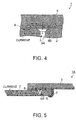
- FIG. 4 shows an example of disposing a conductive shim in a gap between the conductive object 5 and the conductive layer 6, which are shown in FIG. 1 , in order to form a current path between the conductive object 5 and the conductive layer 6.
- electric continuity between the conductive bolt 5A and the conductive layer 6 can be secured by interposing a shim 5D having conductivity between the head of the conductive bolt 5A and the conductive layer 6.
- a material of the shim 5D it is practical to use a material, such as a copper foil or copper paste, which has high electrical conductivity and can be formed to a desired shape easily, similarly to the conductive layer 6.
- the conductive objects 5 can certainly be made to electrically contact with the conductive layer 6 in a state where the conductive objects 5 have been completely embedded in the first structural member 2, using the conductive shims 5D and the countersunk conductive bolts 5A together. That is, the conductive objects 5 can be made to contact with the conductive layer 6, without protruding from the first structural member 2.
- a shape of the first structural member 2 including a main panel or the like is designed by a known method.
- a shape of the second structural member 3, such as an access panel to a fuel tank, to be coupled to the first structural member 2 is also designed by a known method.
- positions of the fasteners 4 for coupling the first structural member 2 to the second structural member 3 are determined.
- the fasteners 4 are designed to be inserted into insertion holes formed in the portions where the first structural member 2 and the second structural member 3 have been overlapped with each other so that the fasteners 4 are in electrically non-contact with each of the first structural member 2 and the second structural member 3 in the insertion holes. That is, the fasteners 4 are designed as the clearance fit.
- positions of the conductive bolts 5A used as the conductive objects 5 for forming current pathways which lead current flowing inside the first structural member 2 to the second structural member 3 side are determined.
- positions of the conductive bolts 5A for preventing a spark between the fasteners 4, and the first structural member 2 and the second structural member 3 are determined.
- the design information is created so as to form the conductive layer 6 between the first structural member 2 and the second structural member 3.
- positions of the conductive bolts 5A for forming current paths which lead current flowing inside the first structural member 2 to the conductive layer 6 in the second structural member 3 side are determined.
- the design information of the structure 1 for an aircraft can be created. Then, the created design information of the structure 1 for an aircraft can be provided to an airframe maker, a parts maker or the like of an aircraft.
- the structure 1 for an aircraft can be manufactured according to the created design information.
- the structure 1 for an aircraft can be manufactured by the following procedures.
- the first structural member 2 is manufactured by a known method according to design specifications.
- the second structural member 3 to be coupled to the first structural member 2 is also manufactured by a known method according to design specifications.
- the conductive objects 5 for preventing a spark between the fasteners 4, for coupling the first structural member 2 to the second structural member 3, and each of the first structural member 2 and the second structural member 3 are embedded in the first structural member 2.
- the conductive bolts 5A used as the conductive objects 5 are inserted into through holes formed in the first structural member 2, and fixed by the conductive nuts 5B respectively. Furthermore, when the tips of the conductive bolts 5A and the conductive nuts 5B protrude to the fuel side, protruding portions are insulated by the insulation caps 5C for conductors.
- the first structural member 2 and the second structural member 3 are overlapped with each other, and then, insertion holes of the fasteners 4 are formed in the portions where the first structural member 2 and the second structural member 3 have been overlapped with each other.
- the conductive layer 6, such as a copper foil, is disposed between the first structural member 2 and the second structural member 3.
- the first structural member 2 and the second structural member 3 are coupled to each other by inserting the fasteners 4 into the insertion holes penetrating the first structural member 2 and the second structural member 3.
- the fasteners 4 are inserted so that the fasteners 4 are in electrically non-contact with the first structural member 2 and the second structural member 3 in the insertion holes. That is, the fasteners 4 are inserted to be the clearance fit.
- An insulating sealant may be applied to the connecting bolts 4A used as the fasteners 4.
- the tips of the connecting bolts 4A are fixed by the connecting nuts 4B respectively.
- protruding portions are insulated by the insulation caps 4C for fasteners.
- the conductive layer 6 is disposed between the first structural member 2 and the second structural member 3, and therefore, an end part of the conductive layer 6 lies in the fuel side, the end part in the fuel side of the conductive layer 6 is sealed by the insulator 7.
- the structure 1 for an aircraft as exemplified by FIG. 1 to FIG. 3 can be manufactured.
- the conductive layer 6 is disposed between the first structural member 2 and the second structural member 3, and thereby, gaps are formed between the heads of the conductive bolts 5A and the conductive layer 6, the gaps can be filled by the shims 5D respectively as shown in FIG. 4 .
- the structure 1 for an aircraft has the conductive objects 5 which function as pathways of lightning current so that a spark due to the lightning current may not occur in each clearance formed between the fasteners 4 and each of the first structural member 2 and the second structural member 3 when the first structural member 2 and the second structural member 3 are coupled to each other by the fasteners 4 to be the clearance fit.
- the structure 1 for an aircraft can achieve both connection of aircraft parts in the clearance fit and prevention of a spark at a connected portion of the aircraft parts at the time of a stroke of lightning.
- a spark at the time of a stroke of lightning can be avoided with also securing advantages of the clearance fit, such as avoiding damage of aircraft parts due to the fasteners 4, preventing wear of the fasteners 4, reducing labor at work of attaching and detaching the fasteners 4, and securing degrees of freedom in manufacturing error, which cannot be obtained by the interference fit.
- connection target by the fasteners 4 is an access panel to a fuel tank
- work of attaching and detaching the access panel is required after a flight operation of aircraft. Therefore, attaching an access panel in the clearance fit is important from a viewpoint of facilitating maintenance work.
- the fasteners 4 when an access panel is attached to be the clearance fit, attaching and detaching the fasteners 4 becomes easy, which leads to a reduction of labor required for inspection work. Furthermore, since the fasteners 4 are not easily worn by opening and closing of an access panel, the fasteners 4 can be reused. That is, the lives of the fasteners 4 can be improved.
- the first structural member 2 and the second structural member 3 are made of a composite material, using the metallic fasteners 4 has a high risk that the fasteners 4 each having a high electrical conductivity become current paths.
- the fasteners 4 each having a high electrical conductivity become current paths.
- the first structural member 2 and the second structural member 3 is a composite material, avoiding damage due to the contact with the fasteners 4 is a more important requirement.
- a connection target by the fasteners 4 is a composite material
- a risk in occurrence of a spark can be dramatically reduced by disposing the conductive objects 5 for a lightning current flowing.
- a risk of damage to a composite material due to contact between the fasteners 4 and the composite material can also be dramatically reduced.
- FIG. 5 is a sectional view showing a structure for an aircraft according to the second embodiment of the present invention.
- a structure 1A for an aircraft in the second embodiment shown in FIG. 5 is different from the structure 1 for an aircraft in the first embodiment in a point that insertion holes for inserting the conductive objects 5 into the first structural member 2 are non-through holes instead of through holes.
- Other features of the structure 1A for an aircraft in the second embodiment are not substantially different from those of the structure 1 for an aircraft in the first embodiment. Therefore, only a method of attaching the conductive objects 5 is illustrated. Then, the same elements and corresponding elements are shown by the same signs, and their explanations are omitted.
- each insertion hole for inserting the conductive bolt 5A, as the conductive object 5, into the first structural member 2 may also be a non-through hole (blind hole) instead of a through hole.
- the conductive bolt 5A, as the conductive object 5 can be inserted into a non-through hole, whose inlet lies in the side where the first structural member 2 and the second structural member 3 are overlapped with each other, formed in the first structural member 2.
- the conductive bolt 5A does not protrude from the first structural member 2. Therefore, the conductive nut 5B and the insulation cap 5C for a conductor, as shown in FIG. 3 , can be omitted.
- the first structural member 2 is a casing of fuel tank, the conductive object 5 can be insulated from the inside of the fuel tank more certainly.
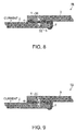
- FIG. 6 is a sectional view showing a modification of the structure 1A for aircraft in the second embodiment shown in FIG. 5 .
- Each conductive object 5 inserted into the first structural member 2 is not limited to the conductive bolt 5A, but an arbitrary object having conductivity can also be inserted as the conductive object 5. For that reason, a conductive pin 5E, such as an easily available knock pin, can also be inserted as the conductive object 5, into a non-through hole of the first structural member 2.
- the conductive pin 5E When the conductive pin 5E is used as the conductive object 5, the conductive pin 5E can be fixed to the first structural member 2 by press fitting of the conductive pin 5E into a non-through hole formed in the first structural member 2, without forming a female screw in the non-through hole. Specifically, the conductive pin 5E can be fixed to the first structural member 2 only by making a non-through hole in the first structural member 2 so that the tolerance of the non-through hole with respect to a diameter of the conductive pin 5E becomes an interference fit. Therefore, the number of parts of the structure 1A for an aircraft can be reduced, thereby the structure 1A for an aircraft can be simplified.
- a gap possibly formed between the conductive pin 5E and the conductive layer 6 disposed as necessary can be filled by the shim 5D having conductivity, as exemplified in FIG. 4 , in order to certainly obtain electrical contact.
- FIG. 7 is a sectional view showing a structure for an aircraft according to the third embodiment of the present invention.
- a structure 1B for an aircraft in the third embodiment shown in FIG. 7 is different from the structure 1A for an aircraft in the second embodiment in a point that the conductive objects 5 are disposed in both the first structural member 2 and the second structural member 3.
- Other features of the structure 1B for an aircraft in the third embodiment are not substantially different from those of the structure 1A for an aircraft in the second embodiment. Therefore, only a method of attaching the conductive objects 5 is illustrated. Then, the same elements and corresponding elements are shown by the same signs, and their explanations are omitted.
- the conductive objects 5 can also be disposed in each of the first structural member 2 and the second structural member 3. More specifically, the conductive bolt 5A, as the conductive object 5, has been inserted into each non-through hole whose inlet lies in the side where the first structural member 2 and the second structural member 3 are overlapped with each other, formed in each of the first structural member 2 and the second structural member 3, in the example shown in FIG. 7 .
- the first conductive bolt 5A inserted into the first structural member 2 and the second conductive bolt 5A inserted into the second structural member 3 have been indirectly and electrically coupled to each other through the conductive layer 6.
- the first conductive bolt 5A and the second conductive bolt 5A are desirable to be made to directly contact and be electrically coupled with each other.
- first conductive bolt 5A and the second conductive bolt 5A are electrically coupled to each other through the conductive layer 6, it is not necessary to make a position of the central axis of the first conductive bolt 5A and a position of the central axis of the second conductive bolt 5A be on a same straight line.
- a current path for leading current from the second structural member 3 to the conductive layer 6 or the first structural member 2 can be formed even when current has flowed from the second structural member 3 toward the first structural member 2 side due to a stroke of lightning. Therefore, even when current has flowed from the second structural member 3 toward the first structural member 2 side, inflow of the current to the fasteners 4 in the clearance fit can be prevented.
- Each insertion hole formed in the second structural member 3 in order to insert the second conductive bolt 5A is a non-through hole. Therefore, the tip of the second conductive bolt 5A does not protrude from the second structural member 3. Thereby, even when the surface of the second structural member 3 in the side where the second structural member 3 is not overlapped with the first structural member 2 is exposed to the atmosphere, a stroke of lightning to the second conductive bolt 5A can be avoided.
- non-through holes which are opened in the side where the first structural member 2 and the second structural member 3 are overlapped with each other, as an insertion hole of the first conductive bolt 5A and an insertion hole of the second conductive bolt 5A, in the first structural member 2 and the second structural member 3 respectively.
- FIG. 8 is a sectional view showing the first modification of the structure 1B for aircraft in the third embodiment shown in FIG. 7 .
- the conductive pins 5E can be used as the conductive objects 5 also in the third embodiment, instead of the conductive bolts 5A.
- the conductive pins 5E are used as the conductive objects 5, it is also appropriate to electrically couple the first conductive pin 5E inserted into the first structural member 2 and the second conductive pin 5E inserted into the second structural member 3 to each other, and prevent the tip of the first conductive pin 5E and the tip of the second conductive pin 5E from protruding from the first structural member 2 and the second structural member 3, respectively, similarly to the case where the conductive bolts 5A are used.
- FIG. 9 is a sectional view showing the second modification of the structure 1B for aircraft in the third embodiment shown in FIG. 7 .
- the single conductive pin 5E may be inserted in the first structural member 2 and the second structural member 3 so that the conductive pin 5E strides over both the first structural member 2 and the second structural member 3. In this case, even when the conductive layer 6 has been omitted, current can be led satisfactorily to the opposed structural member, i.e. the first structural member 2 or the second structural member 3.
- the conductive pins 5E are also detached from the first structural member 2 or the second structural member 3. Therefore, it is appropriate to form insertion holes of the conductive pins 5E in the first structural member 2 or the second structural member 3 with a tolerance to an extent that the conductive pins 5E can be safely detached from the first structural member 2 or the second structural member 3 while electrical contacts between the conductive pins 5E and each of the first structural member 2 and the second structural member 3 can be kept.
- the single conductive pin 5E may be pressed into both the first structural member 2 and the second structural member 3.
- the structure 1B for an aircraft can be highly simplified.
- the respective embodiments as described above may be combined with each other, or conversely some of elements may be omitted.
- the conductive objects 5 may be disposed only in the second structural member 3 depending on an applied part of a structure for an aircraft. Whether the conductive objects 5 are disposed in both the first structural member 2 and the second structural member 3, and whether the conductive objects 5 are disposed in either the first structural member 2 or the second structural member 3 can be determined according to a direction in which current may flow due to a stroke of lightning.
- a direction in which current flows is often approximately specified. This is because lightning preferentially strikes a part, such as a wing tip, having a non-flat structure of an aircraft, in principle. For example, when a wing has been struck by lightning, current flows from the wing tip toward the fuselage side approximately in one direction. Therefore, portions, such as wing tips, where a stroke of lightning is assumed are usually designed so as to obtain resistance to lightning.
- a target or targets in which the conductive objects 5 are to be disposed can be selected from the first structural member 2 and the second structural member 3 depending on which portion a structure for an aircraft is used for, such as a main wing, a tail plane, a center wing, or a fuselage. That is, the conductive objects 5 for preventing a spark can be disposed at arbitrary positions on a web, a flange or the like of an arbitrary structural member, such as a spar, a rib, a panel, and a stringer, which can be the upstream side of current.
- At least parts of the conductive objects 5 can be embedded inside at least one of the first structural member 2 and the second structural member 3, depending on a part to which a structure for an aircraft is applied. Thereby, current paths to lead current flowing inside at least one of the first structural member 2 and the second structural member 3, in which at least the parts of the conductive objects 5 have been embedded, to the other side can be formed.
Landscapes
- Engineering & Computer Science (AREA)
- Aviation & Aerospace Engineering (AREA)
- Mechanical Engineering (AREA)
- Connection Of Plates (AREA)
Abstract
Description
- Embodiments described herein relate generally to a structure for an aircraft, a method of manufacturing a structure for an aircraft and a method of making design information of a structure for an aircraft.
- When a structure, such as a main wing, composing an airframe of an aircraft is struck by lightning, a high current flows. A typical structure of an aircraft is one in which plural panels (skins) are coupled to each other. Therefore, when an aircraft is struck by lightning, a spark may occur in a connection part of panels. Occurrence of a spark may cause scattering of molten materials due to an increase in temperature. Meanwhile, since main planes of an aircraft also generally serve as fuel tanks, it is necessary to take measures to prevent molten materials, caused by a spark, from contacting with a combustible fuel vapor.
- Thus, a technique to couple panels by sandwiching a bridge layer having conductivity has been devised (for example, refer to Japanese Patent Application Publication
JP H02-225 200 A - Furthermore, a technique to prevent current from flowing in fasteners, for coupling a panel to a structural material, by applying an insulating sealant to the fasteners or using insulating washers and/or insulating spacers has also been devised (for example, refer to Japanese Patent Application Publication
JP 2009-227 166 A - In the case of attaching a fastener by the clearance fit, a distance between the fastener and the insertion hole is not necessarily constant. Therefore, even when the insulation property of fasteners is improved using insulating washers and/or insulating spacers, it is still difficult to certainly avoid a possibility that a spark occurs between the fasteners and a panel.
- Thus, a technique to couple panels to each other, with making fasteners contact with insertion holes, has been devised (for example, refer to Japanese Patent Application Publication
JP 2012-192 752 A - However, when a method of coupling panels by fasteners to be the interference fit is adopted, the panels may be damaged due to the contact with the fasteners. In particular, since the use of a composite material as a material of a panel has advanced in recent years, it is an important problem to prevent damage to a composite panel caused by contact between the composite panel and metallic fasteners.
- When a panel is opened and closed like a case of an access panel of a fuel tank, fasteners are attached and detached. Therefore, to prevent damage to a panel due to attachment and detachment of fasteners is a more important problem. Furthermore, in the case of interference fit, not only an access panel is damaged but fasteners also wear whenever the panel is opened and closed. Thereby, it is often necessary to exchange the fasteners for new fasteners in addition to repairing and exchanging the panel.
- Moreover, in the case of interference fit, work of attaching and detaching fasteners takes more time and effort compared to the case of the clearance fit in which a space exists between a panel and each fastener. Furthermore, in the case of interference fit, there is disadvantage that a tolerance in manufacturing error of insertion holes formed on panels to be connection targets becomes small.
- As described above, when the interference fit is adopted as a method of coupling fasteners, disadvantage, such as damage to a panel, wear of fasteners, increase in labor at work of attaching and detaching fasteners, and decrease in degrees of freedom in a manufacturing error, arises. Meanwhile, when the clearance fit is adopted as a method of coupling fasteners, there is a problem that a risk of occurrence of a spark arises at the time of a stroke of lightning since nonuniformity exists in clearances between fasteners and a panel as described above.
- Thus, an object of the present invention is to allow coupling panels for an aircraft under more satisfactory conditions, with preventing a spark at the time of a stroke of lightning.
- In general, according to one embodiment, a structure for an aircraft includes a first structural member, a second structural member, a fastener and a conductive object. The second structural member is coupled to the first structural member. The fastener couples the first structural member to the second structural member. The fastener is inserted into an insertion hole formed in a portion where the first structural member is overlapped with the second structural member. The fastener is in electrically non-contact with each of the first structural member and the second structural member in the insertion hole.
- At least a part of the conductive object is embedded inside at least either one of the first structural member and the second structural member. The conductive object prevents a spark between the fastener and each of the first structural member and the second structural member by forming a current pathway that leads current, flowing inside the at least either one of the first structural member and the second structural member inside which the at least the part is embedded, to the other structural member.
- Further, according to one embodiment, a method of manufacturing a structure for an aircraft includes: manufacturing a first structural member; manufacturing a second structural member to be coupled to the first structural member; embedding at least a part of a conductive object inside at least either one of the first structural member and the second structural member; overlapping the first structural member with the second structural member, and forming an insertion hole in a portion where the first structural member is overlapped with the second structural member; and coupling the first structural member with the second structural member by inserting the fastener into the insertion hole.
- The conductive object forms a current pathway that leads current, flowing inside the at least either one of the first structural member and the second structural member, to the other structural member. The conductive object prevents a spark between a fastener and each of the first structural member and the second structural member. The fastener couples the first structural member to the second structural member. The fastener is in electrically non-contact with each of the first structural member and the second structural member in the insertion hole.
- Further, according to one embodiment, a method of creating design information about a structure for an aircraft includes: designing a shape of a first structural member; designing a shape of a second structural member to be coupled to the first structural member; determining a position of a fastener that couples the first structural member with the second structural member; and determining a position of a conductive object of which at least a part is embedded inside at least either one of the first structural member and the second structural member.
- The fastener is inserted into an insertion hole formed in a portion where the first structural member is overlapped with the second structural member. The fastener is in electrically non-contact with each of the first structural member and the second structural member in the insertion hole. The conductive object prevents a spark between the fastener and each of the first structural member and the second structural member by forming a current pathway that leads current, flowing inside the at least either one of the first structural member and the second structural member inside which the at least the part of the conductive object is embedded, to the other structural member.
- In the accompanying drawings:
- FIG. 1
- is a structural view showing an example of structure for an aircraft according to the first embodiment of the present invention;
- FIG. 2
- is a sectional view at the position A-A showing an attachment state of a fastener shown in
FIG. 1 ; - FIG. 3
- is a sectional view at the position B-B showing an attachment state of a conductive object shown in
FIG. 1 ; - FIG. 4
- shows an example of disposing a conductive shim in a gap between the conductive object and the conductive layer, which are shown in
FIG. 1 , in order to form a current path between the conductive object and the conductive layer; - FIG. 5
- is a sectional view showing a structure for an aircraft according to the second embodiment of the present invention;
- FIG. 6
- is a sectional view showing a modification of the structure for aircraft in the second embodiment shown in
FIG. 5 ; - FIG. 7
- is a sectional view showing a structure for an aircraft according to the third embodiment of the present invention;
- FIG. 8
- is a sectional view showing the first modification of the structure for aircraft in the third embodiment shown in
FIG. 7 ; and - FIG. 9
- is a sectional view showing the second modification of the structure for aircraft in the third embodiment shown in
FIG. 7 . - A structure for an aircraft, a method of manufacturing a structure for an aircraft and a method of making design information of a structure for an aircraft according to embodiments of the present invention will be described with reference to the accompanying drawings.
-
FIG. 1 is a structural view showing an example of structure for an aircraft according to the first embodiment of the present invention,FIG. 2 is a sectional view at the position A-A showing an attachment state of a fastener shown inFIG. 1 , andFIG. 3 is a sectional view at the position B-B showing an attachment state of a conductive object shown inFIG. 1 . - A
structure 1 for an aircraft has at least the firststructural member 2, the secondstructural member 3,fasteners 4, andconductive objects 5. The secondstructural member 3 is coupled to the firststructural member 2 by thefasteners 4. Specifically, an end portion of the secondstructural member 3 is overlapped with an end portion of the firststructural member 2. - Then, insertion holes of the
fasteners 4 are formed at the portion where the firststructural member 2 has been overlapped with the secondstructural member 3. Thus, thefasteners 4 are inserted in the insertion holes formed at the portion where the firststructural member 2 has been overlapped with the secondstructural member 3, thereby the secondstructural member 3 is coupled to the firststructural member 2. - In particular, the
fasteners 4 are inserted so that thefasteners 4 are in electrically non-contact with any of the firststructural member 2 and the secondstructural member 3 in the insertion holes. That is, thefasteners 4 are inserted in the insertion holes to be the clearance fit. Each of thefasteners 4 can be composed of a connectingbolt 4A and a connectingnut 4B as shown inFIG. 2 . -
FIG. 1 shows an example case where the firststructural member 2 is a panel of a main wing which also serves as a casing of a fuel tank while the secondstructural member 3 is each of access panels to the fuel tank. Specifically, two rectangular opening parts for accessing the fuel tank are formed on the plate firststructural member 2. Each of the two opening parts formed on the firststructural member 2 is closed by the plate secondstructural member 3 which is the access panel. - In this case, the second
structural member 3 which is an access panel is often disposed in the air side, as shown inFIG. 2 , so that the secondstructural member 3 can be opened and closed. The size of the secondstructural member 3 and the size of each opening of the firststructural member 2 are determined so that an edge of the secondstructural member 3 is overlapped with an edge of the firststructural member 2 to allow the secondstructural member 3 to be attached to and detached from the firststructural member 2. - Then, the second
structural member 3 is coupled with the firststructural member 2 by thefasteners 4 in the portion where the firststructural member 2 and the secondstructural member 3 are overlapped with each other. That is, access panels are attached to the panel of the main wing in clearance fit by thefasteners 4. - The internal space of the first
structural member 2 whose openings are closed by the secondstructural members 3 serves as the fuel tank. That is, the space side enclosed by the firststructural member 2 and the secondstructural members 3 is the fuel side. Therefore, each connectingbolt 4A is inserted from the atmosphere side toward the fuel side as shown inFIG. 2 so that each of the secondstructural members 3 can be opened and closed. - That is, each connecting
bolt 4A is inserted from the secondstructural member 3 side to the firststructural member 2 side. Therefore, the head of each connectingbolt 4A protrudes from the secondstructural member 3 to the atmosphere side. Meanwhile, the tip of each connectingbolt 4A protrudes from the firststructural member 2 to the fuel side. - Then, the tip of each connecting
bolt 4A is coupled to the connectingnut 4B in the fuel side of the firststructural member 2, which is inside the fuel tank. Thereby, the firststructural member 2 and each of the secondstructural members 3 are fixed to each other by thefasteners 4. - When the above-mentioned
structure 1 for an aircraft, such as a main wing with which access panels are attached, is struck by lightning, current flows through thestructure 1 for the aircraft. Not only when the firststructural member 2 and the secondstructural members 3 are made of a metal, but also when the firststructural member 2 and the secondstructural members 3 are made of a composite material, current flows through the surface and inside of the firststructural member 2. In particular, when a composite material is CFRP (Carbon Fiber Reinforced Plastics), carbon fibers can be conductors of a lightning current. - When a lightning current propagates in the space in the
structure 1 for an aircraft, a spark occurs. When a spark occurs, a part of thefasteners 4, the firststructural member 2, the secondstructural member 3 or the like may melt and scatter due to an increase in temperature. Therefore, it is necessary to prevent occurrence of a spark. In particular, when thestructure 1 for an aircraft is a wing structure which also serves as a fuel tank, it is essential to prevent melts caused by a spark from contacting with a combustible fuel vapor. - It is a gap between the
fasteners 4 attached in the clearance fit and each of the firststructural member 2 and the secondstructural member 3 that has a high risk of occurrence of a spark in thestructure 1 for an aircraft. In particular, when at least one of the firststructural member 2 and the secondstructural member 3 is made of a composite material, there is a high risk that themetallic fasteners 4 with high conductivity become paths of a lightning current. - Thus, an insulating sealant may be applied to each of the
fasteners 4. Alternatively, insulating bolts each consisting of an insulating material may also be used as thefasteners 4. Thereby, occurrence of a spark, caused by a lightning current flowing into thefasteners 4 from the firststructural member 2 and the secondstructural member 3, can be prevented to some extent. - The tips of the connecting
bolts 4A protruding from the firststructural member 2 to the fuel side and the connecting nuts 4B are sealed byinsulation caps 4C for fasteners. As shown inFIG. 2 , dome nuts are practically used as the connecting nuts 4B. In this case, the dome nuts are sealed by the insulation caps 4C for fasteners since the tips of the connectingbolts 4A are inside the dome nuts. Thereby, thefasteners 4 protruding from the firststructural member 2 to the fuel side are insulated from the inside of the fuel tank. - Since the
fasteners 4 are attached to the firststructural member 2 and the secondstructural members 3 by the clearance fit, a possibility that current flows into thefasteners 4 through gaps still remains. This is because the clearance between each connectingbolt 4A, and the firststructural member 2 and the secondstructural member 3 is uneven when the connectingbolt 4A is attached in the clearance fit, regardless of whether an insulating sealant is applied to the connectingbolt 4A. In particular, when an insulating sealant is applied to the connectingbolt 4A, a very small gap may be formed in the insertion hole after the insulating sealant has been solidified in the insertion hole. - Furthermore, when at least one of the first
structural member 2 and the secondstructural member 3 is made of a composite material and the connectingbolts 4A used as thefasteners 4 are metallic, a risk that current flows into the connectingbolts 4A each having high electrical conductivity becomes high. Therefore, it is important to further reduce the risk that current flows into the connectingbolts 4A. - Thus, the
conductive objects 5 for preventing a spark between thefasteners 4, and the firststructural member 2 and the secondstructural members 3 are disposed in thestructure 1 for an aircraft. In the example shown in the figures, theconductive objects 5 are disposed in the portions where the firststructural member 2 and the secondstructural members 3 are overlapped with each other. - More specifically,
conductive bolts 5A penetrating the firststructural member 2 from the secondstructural member 3 side, which is overlapped with the atmosphere side of the firststructural member 2, toward the fuel side are disposed as theconductive objects 5. - Therefore, the heads of the
conductive bolts 5A are embedded in the firststructural member 2 side between the firststructural member 2 and the secondstructural member 3. Specifically, the heads of theconductive bolts 5A inserted in insertion holes of the firststructural member 2 are covered with the secondstructural members 3. Therefore, the heads of theconductive bolts 5A are not exposed to the atmosphere side. - Meanwhile,
conductive nuts 5B are fastened to male screws formed on the tip portions of theconductive bolts 5A protruding from the firststructural member 2 to the fuel side. Specifically, theconductive bolts 5A are fixed to the firststructural member 2 by fastening theconductive nuts 5B to the tip portions of theconductive bolts 5A. - In this case, the tip sides of the
conductive bolts 5A and theconductive nuts 5B protrude to the fuel side of the firststructural member 2. Therefore, the tip sides of theconductive bolts 5A and theconductive nuts 5B are sealed byinsulation caps 5C for conductors, similarly to the tip sides of the connectingbolts 4A and the connecting nuts 4B. Thereby, the tip portions of theconductive bolts 5A and theconductive nuts 5B protruding from the firststructural member 2 to the fuel side are insulated from the inside of the fuel tank by the insulation caps 5C as protecting members. - It is practical to use dome nuts also for the
conductive nuts 5B. Meanwhile, it is practical to use sleeve bolts for theconductive bolts 5A so that theconductive bolts 5A electrically contact with the firststructural member 2 without damaging the firststructural member 2. - When the above-mentioned
conductive bolts 5A are disposed in the firststructural member 2, current paths which lead current, flowing inside the firststructural member 2, to the secondstructural member 3 side are formed by theconductive bolts 5A. In other words, each of theconductive bolts 5A functions as a current pathway which leads current flowing inside the firststructural member 2 to the secondstructural member 3 side. - Specifically, current flowing inside the first
structural member 2 toward connected portions with the secondstructural members 3 can be led into theconductive bolts 5A. Then, the current can flow from the heads of theconductive bolts 5A to surface layers of the secondstructural members 3 in the firststructural member 2 side. - Therefore, when the
conductive bolts 5A are disposed as theconductive objects 5 in the firststructural member 2, current flowing inside the firststructural member 2 can be prevented from flowing into the connectingbolts 4A for coupling the firststructural member 2 to the secondstructural member 3 in the clearance fit. - Thereby, occurrence of a spark between the connecting
bolts 4A, and the firststructural member 2 and the secondstructural members 3 can be prevented. Then, the connectingbolts 4A can be used for coupling the firststructural member 2 to the secondstructural member 3, without flowing current. Meanwhile, theconductive bolts 5A can be used not for coupling the firststructural member 2 to the secondstructural member 3 but for theconductive objects 5 flowing current. - Furthermore, since the head sides of the
conductive bolts 5A are covered by the secondstructural members 3, the head sides of theconductive bolts 5A are not exposed to the atmosphere side. Therefore, a situation where theconductive bolt 5A is struck by lightning and a high current flows through theconductive bolt 5A, which results in melting of theconductive bolt 5A, can also be avoided. - In the example shown in
FIG. 1 , theconductive bolts 5A are disposed at an appropriate interval between the connectingbolts 4A for attaching the access panels for the fuel tank to the main wing panel, in the portions where the access panels and the main wing panel are overlapped with each other. - In order to prevent inflow of current to the connecting
bolts 4A more certainly, it is effective to dispose aconductive layer 6, contacting with theconductive objects 5, between the firststructural member 2 and the secondstructural member 3, in addition to theconductive bolts 5A, as shown in the figures. It is practical to use a material, such as a copper foil or copper paste, which has high electrical conductivity and can be thinned, as theconductive layer 6. - In the example shown in
FIG. 1 , the secondstructural members 3 are the access panels to the fuel tank, and the portions where the firststructural member 2 and the secondstructural members 3 are overlapped with each other have approximately rectangular ring shapes. Therefore, the ring-shapedconductive layers 6 have been disposed at the portions where the firststructural member 2 and the secondstructural members 3 are overlapped with each other. - In other words, the access panels are attached to the main panel so that the
conductive layer 6 is sandwiched between each access panel and the main panel. Note that, since the connectingbolts 4A are in the clearance fit, the connectingbolts 4A do not also contact with theconductive layers 6. Therefore, theconductive layers 6 have insertion holes each having a diameter sufficiently larger than the diameter of the connectingbolts 4A so that theconductive layers 6 do not contact with the connectingbolts 4A. - When each head of the
conductive bolts 5A is made to contact with theconductive layer 6 as shown inFIG. 3 , current flowing inside the firststructural member 2 toward the secondstructural member 3 side is led to theconductive layer 6 through theconductive bolts 5A. Meanwhile, current flowing in the surface layer, in the atmosphere side, of the firststructural member 2 toward the secondstructural member 3 side is directly led to theconductive layer 6, without going through theconductive bolts 5A. That is, all current flowing in the firststructural member 2 toward the secondstructural member 3 side can be led to theconductive layer 6. - When current is led to the
conductive layer 6, a part of the current may flow into the fuel side of the secondstructural member 3, i.e. the surface layer, in the firststructural member 2 side, of the secondstructural member 3. However, a large part of the current flows again into the firststructural member 2 in the opposite side, toward a traveling direction of the current, through theconductive layer 6 having a high electrical conductivity. - Specifically, a large part of the current flowing inside the first
structural member 2 is once led to theconductive layer 6 through theconductive bolts 5A, and flows into the inside of the firststructural member 2 again through theconductive bolts 5A in the opposite side toward the traveling direction of the current. That is, a large part of the current flowing in the firststructural member 2 toward the secondstructural member 3 side bypasses the secondstructural member 3. - As described above, pathways of lightning current can be formed by disposing the
conductive layer 6 between each access panel and the main panel, and disposing theconductive bolts 5A, which lead current flowing in the main panel side to theconductive layer 6, between the connectingbolts 4A of the access panels. In other words, electrical conductivity of thewhole structure 1 for an aircraft can be improved. As a result, inflow of current into the connectingbolts 4A can be avoided more certainly. - One verge of the
conductive layer 6 interposed between each access panel and the main panel faces the atmosphere side while the other verge faces the fuel side. Thus, it is desirable to seal the end of theconductive layer 6 in the fuel side by aninsulator 7 as shown in the figures. Furthermore, the end of theconductive layer 6 in the atmosphere side may also be shielded by an insulator. - When the
conductive layer 6 is formed between the firststructural member 2 and the secondstructural member 3, it is important to sufficiently contact the heads of theconductive bolts 5A with theconductive layer 6, in order to form the current paths as described above. - Thus, inserting the countersunk
conductive bolts 5A into the firststructural member 2 as exemplified inFIG. 3 can make theconductive bolts 5A electrically contact with theconductive layer 6, without the heads of theconductive bolts 5A protruding in the secondstructural member 3 side. That is, theconductive objects 5 can be made to electrically contact with theconductive layer 6 in a state where theconductive objects 5 have been completely embedded in the firststructural member 2. - Note that, it is often difficult to accurately align positions of the heads of the countersunk
conductive bolts 5A. Specifically, when theconductive bolts 5A are fastened, the heads of theconductive bolts 5A may dent from the surface of the firststructural member 2. In such a case, it is appropriate to dispose shims having conductivity so that gaps are not formed between the heads of theconductive bolts 5A and theconductive layer 6. -
FIG. 4 shows an example of disposing a conductive shim in a gap between theconductive object 5 and theconductive layer 6, which are shown inFIG. 1 , in order to form a current path between theconductive object 5 and theconductive layer 6. - As exemplified in
FIG. 4 , electric continuity between theconductive bolt 5A and theconductive layer 6 can be secured by interposing ashim 5D having conductivity between the head of theconductive bolt 5A and theconductive layer 6. As a material of theshim 5D, it is practical to use a material, such as a copper foil or copper paste, which has high electrical conductivity and can be formed to a desired shape easily, similarly to theconductive layer 6. - As described above, the
conductive objects 5 can certainly be made to electrically contact with theconductive layer 6 in a state where theconductive objects 5 have been completely embedded in the firststructural member 2, using theconductive shims 5D and the countersunkconductive bolts 5A together. That is, theconductive objects 5 can be made to contact with theconductive layer 6, without protruding from the firststructural member 2. - Next, a method of making design information of the
structure 1 for aircraft and a method of manufacturing thestructure 1 for aircraft will be described. - In the case of creating and providing design information of the
structure 1 for an aircraft as exemplified inFIG. 1 , a shape of the firststructural member 2 including a main panel or the like is designed by a known method. Meanwhile, a shape of the secondstructural member 3, such as an access panel to a fuel tank, to be coupled to the firststructural member 2 is also designed by a known method. - Next, positions of the
fasteners 4 for coupling the firststructural member 2 to the secondstructural member 3 are determined. Thefasteners 4 are designed to be inserted into insertion holes formed in the portions where the firststructural member 2 and the secondstructural member 3 have been overlapped with each other so that thefasteners 4 are in electrically non-contact with each of the firststructural member 2 and the secondstructural member 3 in the insertion holes. That is, thefasteners 4 are designed as the clearance fit. - In addition, positions of the
conductive bolts 5A used as theconductive objects 5 for forming current pathways which lead current flowing inside the firststructural member 2 to the secondstructural member 3 side are determined. In other words, positions of theconductive bolts 5A for preventing a spark between thefasteners 4, and the firststructural member 2 and the secondstructural member 3 are determined. - At this time, preferably, the design information is created so as to form the
conductive layer 6 between the firststructural member 2 and the secondstructural member 3. In this case, positions of theconductive bolts 5A for forming current paths which lead current flowing inside the firststructural member 2 to theconductive layer 6 in the secondstructural member 3 side are determined. - By such procedures, the design information of the
structure 1 for an aircraft, as exemplified byFIG. 1 to FIG. 3 , can be created. Then, the created design information of thestructure 1 for an aircraft can be provided to an airframe maker, a parts maker or the like of an aircraft. When the design information of thestructure 1 for an aircraft is created, thestructure 1 for an aircraft can be manufactured according to the created design information. Thestructure 1 for an aircraft can be manufactured by the following procedures. - Firstly, the first
structural member 2 is manufactured by a known method according to design specifications. Meanwhile, the secondstructural member 3 to be coupled to the firststructural member 2 is also manufactured by a known method according to design specifications. - Next, the
conductive objects 5 for preventing a spark between thefasteners 4, for coupling the firststructural member 2 to the secondstructural member 3, and each of the firststructural member 2 and the secondstructural member 3 are embedded in the firststructural member 2. - Specifically, the
conductive bolts 5A used as theconductive objects 5 are inserted into through holes formed in the firststructural member 2, and fixed by theconductive nuts 5B respectively. Furthermore, when the tips of theconductive bolts 5A and theconductive nuts 5B protrude to the fuel side, protruding portions are insulated by the insulation caps 5C for conductors. - Next, the first
structural member 2 and the secondstructural member 3 are overlapped with each other, and then, insertion holes of thefasteners 4 are formed in the portions where the firststructural member 2 and the secondstructural member 3 have been overlapped with each other. At this time, preferably, theconductive layer 6, such as a copper foil, is disposed between the firststructural member 2 and the secondstructural member 3. - Then, the first
structural member 2 and the secondstructural member 3 are coupled to each other by inserting thefasteners 4 into the insertion holes penetrating the firststructural member 2 and the secondstructural member 3. Note that, thefasteners 4 are inserted so that thefasteners 4 are in electrically non-contact with the firststructural member 2 and the secondstructural member 3 in the insertion holes. That is, thefasteners 4 are inserted to be the clearance fit. - An insulating sealant may be applied to the connecting
bolts 4A used as thefasteners 4. The tips of the connectingbolts 4A are fixed by the connecting nuts 4B respectively. When the tips of the connectingbolts 4A and the connecting nuts 4B protrude to the fuel side, protruding portions are insulated by the insulation caps 4C for fasteners. Furthermore, when theconductive layer 6 is disposed between the firststructural member 2 and the secondstructural member 3, and therefore, an end part of theconductive layer 6 lies in the fuel side, the end part in the fuel side of theconductive layer 6 is sealed by theinsulator 7. - Thereby, the
structure 1 for an aircraft as exemplified byFIG. 1 to FIG. 3 can be manufactured. Note that, when theconductive layer 6 is disposed between the firststructural member 2 and the secondstructural member 3, and thereby, gaps are formed between the heads of theconductive bolts 5A and theconductive layer 6, the gaps can be filled by theshims 5D respectively as shown inFIG. 4 . - As described above, the
structure 1 for an aircraft has theconductive objects 5 which function as pathways of lightning current so that a spark due to the lightning current may not occur in each clearance formed between thefasteners 4 and each of the firststructural member 2 and the secondstructural member 3 when the firststructural member 2 and the secondstructural member 3 are coupled to each other by thefasteners 4 to be the clearance fit. - Therefore, the
structure 1 for an aircraft can achieve both connection of aircraft parts in the clearance fit and prevention of a spark at a connected portion of the aircraft parts at the time of a stroke of lightning. Specifically, a spark at the time of a stroke of lightning can be avoided with also securing advantages of the clearance fit, such as avoiding damage of aircraft parts due to thefasteners 4, preventing wear of thefasteners 4, reducing labor at work of attaching and detaching thefasteners 4, and securing degrees of freedom in manufacturing error, which cannot be obtained by the interference fit. - In particular, when a connection target by the
fasteners 4 is an access panel to a fuel tank, work of attaching and detaching the access panel is required after a flight operation of aircraft. Therefore, attaching an access panel in the clearance fit is important from a viewpoint of facilitating maintenance work. - Specifically, when an access panel is attached to be the clearance fit, attaching and detaching the
fasteners 4 becomes easy, which leads to a reduction of labor required for inspection work. Furthermore, since thefasteners 4 are not easily worn by opening and closing of an access panel, thefasteners 4 can be reused. That is, the lives of thefasteners 4 can be improved. - This is not only limited to an access panel, but it is similar in a case of coupling the second
structural member 3, which requires attaching and detaching, to the firststructural member 2 by thefasteners 4. - When at least one of the first
structural member 2 and the secondstructural member 3 is made of a composite material, using themetallic fasteners 4 has a high risk that thefasteners 4 each having a high electrical conductivity become current paths. In addition, when at least one of the firststructural member 2 and the secondstructural member 3 is a composite material, avoiding damage due to the contact with thefasteners 4 is a more important requirement. - Therefore, when a connection target by the
fasteners 4 is a composite material, a risk in occurrence of a spark can be dramatically reduced by disposing theconductive objects 5 for a lightning current flowing. In addition, a risk of damage to a composite material due to contact between thefasteners 4 and the composite material can also be dramatically reduced. -
FIG. 5 is a sectional view showing a structure for an aircraft according to the second embodiment of the present invention. - A
structure 1A for an aircraft in the second embodiment shown inFIG. 5 is different from thestructure 1 for an aircraft in the first embodiment in a point that insertion holes for inserting theconductive objects 5 into the firststructural member 2 are non-through holes instead of through holes. Other features of thestructure 1A for an aircraft in the second embodiment are not substantially different from those of thestructure 1 for an aircraft in the first embodiment. Therefore, only a method of attaching theconductive objects 5 is illustrated. Then, the same elements and corresponding elements are shown by the same signs, and their explanations are omitted. - As shown in
FIG. 5 , each insertion hole for inserting theconductive bolt 5A, as theconductive object 5, into the firststructural member 2 may also be a non-through hole (blind hole) instead of a through hole. Specifically, theconductive bolt 5A, as theconductive object 5, can be inserted into a non-through hole, whose inlet lies in the side where the firststructural member 2 and the secondstructural member 3 are overlapped with each other, formed in the firststructural member 2. - In this case, the
conductive bolt 5A does not protrude from the firststructural member 2. Therefore, theconductive nut 5B and theinsulation cap 5C for a conductor, as shown inFIG. 3 , can be omitted. When the firststructural member 2 is a casing of fuel tank, theconductive object 5 can be insulated from the inside of the fuel tank more certainly. - Note that, it is practical to use bolts having no sleeve portions as the
conductive bolts 5A and form female screws in the firststructural member 2, in order to fix theconductive bolts 5A to the firststructural member 2. Theconductive bolts 5A are not attached and detached frequently, unlike the connectingbolts 4A for an access panel or the like. Therefore, damage to the firststructural member 2 resulting from contact between theconductive bolts 5A and the firststructural member 2 can be minimized. -
FIG. 6 is a sectional view showing a modification of thestructure 1A for aircraft in the second embodiment shown inFIG. 5 . - Each
conductive object 5 inserted into the firststructural member 2 is not limited to theconductive bolt 5A, but an arbitrary object having conductivity can also be inserted as theconductive object 5. For that reason, aconductive pin 5E, such as an easily available knock pin, can also be inserted as theconductive object 5, into a non-through hole of the firststructural member 2. - When the
conductive pin 5E is used as theconductive object 5, theconductive pin 5E can be fixed to the firststructural member 2 by press fitting of theconductive pin 5E into a non-through hole formed in the firststructural member 2, without forming a female screw in the non-through hole. Specifically, theconductive pin 5E can be fixed to the firststructural member 2 only by making a non-through hole in the firststructural member 2 so that the tolerance of the non-through hole with respect to a diameter of theconductive pin 5E becomes an interference fit. Therefore, the number of parts of thestructure 1A for an aircraft can be reduced, thereby thestructure 1A for an aircraft can be simplified. - In addition, when the
conductive pin 5E is made to contact with the firststructural member 2 by press fitting of theconductive pin 5E into the firststructural member 2, electrical contact between theconductive pin 5E and the firststructural member 2 can certainly be obtained. - As a matter of course, also in a case of using the
conductive pin 5E as theconductive object 5, a gap possibly formed between theconductive pin 5E and theconductive layer 6 disposed as necessary can be filled by theshim 5D having conductivity, as exemplified inFIG. 4 , in order to certainly obtain electrical contact. -
FIG. 7 is a sectional view showing a structure for an aircraft according to the third embodiment of the present invention. - A
structure 1B for an aircraft in the third embodiment shown inFIG. 7 is different from thestructure 1A for an aircraft in the second embodiment in a point that theconductive objects 5 are disposed in both the firststructural member 2 and the secondstructural member 3. Other features of thestructure 1B for an aircraft in the third embodiment are not substantially different from those of thestructure 1A for an aircraft in the second embodiment. Therefore, only a method of attaching theconductive objects 5 is illustrated. Then, the same elements and corresponding elements are shown by the same signs, and their explanations are omitted. - As shown in
FIG. 7 , theconductive objects 5 can also be disposed in each of the firststructural member 2 and the secondstructural member 3. More specifically, theconductive bolt 5A, as theconductive object 5, has been inserted into each non-through hole whose inlet lies in the side where the firststructural member 2 and the secondstructural member 3 are overlapped with each other, formed in each of the firststructural member 2 and the secondstructural member 3, in the example shown inFIG. 7 . - Then, the first
conductive bolt 5A inserted into the firststructural member 2 and the secondconductive bolt 5A inserted into the secondstructural member 3 have been indirectly and electrically coupled to each other through theconductive layer 6. In a case of omitting theconductive layer 6, the firstconductive bolt 5A and the secondconductive bolt 5A are desirable to be made to directly contact and be electrically coupled with each other. - When the first
conductive bolt 5A and the secondconductive bolt 5A are electrically coupled to each other through theconductive layer 6, it is not necessary to make a position of the central axis of the firstconductive bolt 5A and a position of the central axis of the secondconductive bolt 5A be on a same straight line. - As described above, when the
conductive object 5 is also disposed in the secondstructural member 3 side, a current path for leading current from the secondstructural member 3 to theconductive layer 6 or the firststructural member 2 can be formed even when current has flowed from the secondstructural member 3 toward the firststructural member 2 side due to a stroke of lightning. Therefore, even when current has flowed from the secondstructural member 3 toward the firststructural member 2 side, inflow of the current to thefasteners 4 in the clearance fit can be prevented. - Each insertion hole formed in the second
structural member 3 in order to insert the secondconductive bolt 5A is a non-through hole. Therefore, the tip of the secondconductive bolt 5A does not protrude from the secondstructural member 3. Thereby, even when the surface of the secondstructural member 3 in the side where the secondstructural member 3 is not overlapped with the firststructural member 2 is exposed to the atmosphere, a stroke of lightning to the secondconductive bolt 5A can be avoided. - That is, it is important to prevent both the tip of the first
conductive bolt 5A inserted in the firststructural member 2 and the tip of the secondconductive bolt 5A inserted in the second structural member, from protruding from the firststructural member 2 and the secondstructural member 3 respectively. Therefore, both the head of the firstconductive bolt 5A and the head of the secondconductive bolt 5A lie in the side where the firststructural member 2 and the secondstructural member 3 are overlapped with each other. - In other words, it is appropriate to form non-through holes, which are opened in the side where the first
structural member 2 and the secondstructural member 3 are overlapped with each other, as an insertion hole of the firstconductive bolt 5A and an insertion hole of the secondconductive bolt 5A, in the firststructural member 2 and the secondstructural member 3 respectively. -
FIG. 8 is a sectional view showing the first modification of thestructure 1B for aircraft in the third embodiment shown inFIG. 7 . - As shown in
FIG. 8 , theconductive pins 5E can be used as theconductive objects 5 also in the third embodiment, instead of theconductive bolts 5A. When theconductive pins 5E are used as theconductive objects 5, it is also appropriate to electrically couple the firstconductive pin 5E inserted into the firststructural member 2 and the secondconductive pin 5E inserted into the secondstructural member 3 to each other, and prevent the tip of the firstconductive pin 5E and the tip of the secondconductive pin 5E from protruding from the firststructural member 2 and the secondstructural member 3, respectively, similarly to the case where theconductive bolts 5A are used. -
FIG. 9 is a sectional view showing the second modification of thestructure 1B for aircraft in the third embodiment shown inFIG. 7 . - When the
conductive pins 5E are used as theconductive objects 5, the singleconductive pin 5E may be inserted in the firststructural member 2 and the secondstructural member 3 so that theconductive pin 5E strides over both the firststructural member 2 and the secondstructural member 3. In this case, even when theconductive layer 6 has been omitted, current can be led satisfactorily to the opposed structural member, i.e. the firststructural member 2 or the secondstructural member 3. - When the first
structural member 2 or the secondstructural member 3 needs to be detached, theconductive pins 5E are also detached from the firststructural member 2 or the secondstructural member 3. Therefore, it is appropriate to form insertion holes of theconductive pins 5E in the firststructural member 2 or the secondstructural member 3 with a tolerance to an extent that theconductive pins 5E can be safely detached from the firststructural member 2 or the secondstructural member 3 while electrical contacts between theconductive pins 5E and each of the firststructural member 2 and the secondstructural member 3 can be kept. - Conversely, when the first
structural member 2 or the secondstructural member 3 does not need to be detached, the singleconductive pin 5E may be pressed into both the firststructural member 2 and the secondstructural member 3. In this case, thestructure 1B for an aircraft can be highly simplified. - While certain embodiments have been described, these embodiments have been presented by way of example only, and are not intended to limit the scope of the invention. Indeed, the novel methods and systems described herein may be embodied in a variety of other forms; furthermore, various omissions, substitutions and changes in the form of the methods and systems described herein may be made without departing from the spirit of the invention. The accompanying claims and their equivalents are intended to cover such forms or modifications as would fall within the scope and spirit of the invention.
- For example, the respective embodiments as described above may be combined with each other, or conversely some of elements may be omitted. As a specific example, the
conductive objects 5 may be disposed only in the secondstructural member 3 depending on an applied part of a structure for an aircraft. Whether theconductive objects 5 are disposed in both the firststructural member 2 and the secondstructural member 3, and whether theconductive objects 5 are disposed in either the firststructural member 2 or the secondstructural member 3 can be determined according to a direction in which current may flow due to a stroke of lightning. - When an aircraft is struck by lightning, a direction in which current flows is often approximately specified. This is because lightning preferentially strikes a part, such as a wing tip, having a non-flat structure of an aircraft, in principle. For example, when a wing has been struck by lightning, current flows from the wing tip toward the fuselage side approximately in one direction. Therefore, portions, such as wing tips, where a stroke of lightning is assumed are usually designed so as to obtain resistance to lightning.
- That is, how current flows at the time of a stroke of lightning changes, depending on an applied part of a structure for an aircraft, among a case where current flows only from the first
structural member 2 to the secondstructural member 3, a case where current flows only from the secondstructural member 3 to the firststructural member 2, and a case where current can flow from the firststructural member 2 and the secondstructural member 3 to the other bidirectionally. - Therefore, a target or targets in which the
conductive objects 5 are to be disposed can be selected from the firststructural member 2 and the secondstructural member 3 depending on which portion a structure for an aircraft is used for, such as a main wing, a tail plane, a center wing, or a fuselage. That is, theconductive objects 5 for preventing a spark can be disposed at arbitrary positions on a web, a flange or the like of an arbitrary structural member, such as a spar, a rib, a panel, and a stringer, which can be the upstream side of current. - Specifically, at least parts of the
conductive objects 5 can be embedded inside at least one of the firststructural member 2 and the secondstructural member 3, depending on a part to which a structure for an aircraft is applied. Thereby, current paths to lead current flowing inside at least one of the firststructural member 2 and the secondstructural member 3, in which at least the parts of theconductive objects 5 have been embedded, to the other side can be formed. - Note that, it is important to avoid a stroke of lightning on a flat portion of an airframe. Therefore, it is appropriate to prevent the
conductive objects 5 from protruding in the atmosphere side. Thus, protrusion of theconductive objects 5 in the atmosphere side can be avoided by inserting theconductive objects 5 into non-through holes, whose inlets lie in the side where the firststructural member 2 and the secondstructural member 3 are overlapped with each other, formed in at least one of the firststructural member 2 and the secondstructural member 3. Similarly, protrusion of theconductive objects 5 into an inside of a fuel tank can be avoided.List of Reference Signs 1 structure 5A conductive bolt 2 first structural member 5B conductive nut 3 second structural member 5C insulation cap 4 fastener 5D shim 4A connecting bolt 5E conductive pin 4B connecting nut 6 conductive layer 4C insulation cap 7 insulator 5 conductive object
Claims (12)
- A structure for an aircraft, comprising:- a first structural member (2);- a second structural member (3) coupled to the first structural member (2);- a fastener (4) that couples the first structural member (2) to the second structural member (3), the fastener (4) being inserted into an insertion hole formed in a portion where the first structural member (2) is overlapped with the second structural member (3), the fastener (4) being in electrically non-contact with each of the first structural member (2) and the second structural member (3) in the insertion hole; and- a conductive object (5) of which at least a part is embedded inside at least either one of the first structural member (2) and the second structural member (3), the conductive object (5) preventing a spark between the fastener (4) and each of the first structural member (2) and the second structural member (3) by forming a current pathway that leads current, flowing inside the at least either one of the first structural member (2) and the second structural member (3) inside which the at least the part is embedded, to the other structural member.
- The structure according to claim 1,
further comprising:a conductive layer (6) disposed between the first structural member (2) and the second structural member (3), the conductive layer (6) contacting with the conductive object (5). - The structure according to claim 1 or 2,
wherein the conductive object (5) is disposed in the portion where the first structural member (2) is overlapped with the second structural member (3). - The structure according to any one of claims 1 to 3,
wherein the at least either one of the first structural member (2) and the second structural member (3), inside which at least a part of the conductive object (5) is embedded, is made of a composite material. - The structure according to any one of claims 1 to 4,
wherein the first structural member (2) is a panel of a wing that serves as a casing of a fuel tank and the second structural member (3) is an access panel to the fuel tank. - The structure according to any one of claims 1 to 5,
wherein a bolt (5A) is disposed, as the conductive object, in the portion where the first structural member (2) is overlapped with the second structural member (3), the bolt (5A) penetrating the first structural member (2) from a side of the second structural member (3) toward a fuel side, the second structural member (3) being overlapped with an air side of the first structural member (2), and
wherein the structure for the aircraft further comprises:- a nut (5B) that fixes the bolt (5A) to the first structural member (2), the nut (5B) being fastened with a male screw formed on a tip portion of the bolt (5A) protruding from the first structural member (2) to the fuel side;
and- a protecting member (5C) that insulates the tip portion of the bolt (5A) and the nut (5B). - The structure according to any one of claims 1 to 6,
wherein a pin (5E) or a bolt (5A) is disposed as the conductive object, the pin (5E) or the bolt (5A) being inserted into a blind hole formed in the at least either one of the first structural member (2) and the second structural member (3), an inlet of the blind hole being formed in a side where the first structural member (2) is overlapped with the second structural member (3). - The structure according to any one of claims 1 to 7,
wherein each of a first pin (5E) or a first bolt (5A) and a second pin (5E) or a second bolt (5A) is disposed as the conductive object, the first pin (5E) or the first bolt (5A) being inserted into a first blind hole formed in the first structural member (2), the second pin (5E) or the second bolt (5A) being inserted into a second blind hole formed in the second structural member (3), each of inlets of the first and second blind holes being formed in the side where the first structural member (2) is overlapped with the second structural member (3), the first pin (5E) or the first bolt (5A) being electrically coupled with the second pin (5E) or the second bolt (5A) directly or indirectly. - The structure according to any one of claims 1 to 8,
wherein the fastener (4) is applied with an insulating sealant. - The structure according to any one of claim1 to 9,
further comprising:a conductive shim (5D) disposed in a gap between the conductive object (5A) and the conductive layer (6), the shim (5D) forming a current pathway between the conductive object (5A) and the conductive layer (6). - A method of manufacturing a structure for an aircraft comprising:- manufacturing a first structural member (2);- manufacturing a second structural member (3) to be coupled to the first structural member (2);- embedding at least a part of a conductive object (5) inside at least either one of the first structural member (2) and the second structural member (3), the conductive object (5) forming a current pathway that leads current, flowing inside the at least either one of the first structural member (2) and the second structural member (3), to the other structural member, the conductive object (5) preventing a spark between a fastener (4) and each of the first structural member (2) and the second structural member (3), the fastener (4) coupling the first structural member (2) to the second structural member (3);- overlapping the first structural member (2) with the second structural member (3), and forming an insertion hole in a portion where the first structural member (2) is overlapped with the second structural member (3); and- coupling the first structural member (2) with the second structural member (3) by inserting the fastener (4) into the insertion hole, the fastener (4) being in electrically non-contact with each of the first structural member (2) and the second structural member (3) in the insertion hole.
- A method of making design information of a structure for an aircraft comprising:- designing a shape of a first structural member (2);- designing a shape of a second structural member (3) to be coupled to the first structural member (2);- determining a position of a fastener (4) that couples the first structural member (2) with the second structural member (3), the fastener (4) being inserted into an insertion hole formed in a portion where the first structural member (2) is overlapped with the second structural member (3), the fastener (4) being in electrically non-contact with each of the first structural member (2) and the second structural member (3) in the insertion hole; and- determining a position of a conductive object (5) of which at least a part is embedded inside at least either one of the first structural member (2) and the second structural member (3), the conductive object (5) preventing a spark between the fastener (4) and each of the first structural member (2) and the second structural member (3) by forming a current pathway that leads current, flowing inside the at least either one of the first structural member (2) and the second structural member (3) inside which the at least the part of the conductive object (5) is embedded, to the other structural member.
Applications Claiming Priority (1)
| Application Number | Priority Date | Filing Date | Title |
|---|---|---|---|
| JP2015033424A JP6139582B2 (en) | 2015-02-23 | 2015-02-23 | Aircraft structure, aircraft structure manufacturing method, and aircraft structure design information creation method |
Publications (2)
| Publication Number | Publication Date |
|---|---|
| EP3059172A1 true EP3059172A1 (en) | 2016-08-24 |
| EP3059172B1 EP3059172B1 (en) | 2018-04-11 |
Family
ID=55411271
Family Applications (1)
| Application Number | Title | Priority Date | Filing Date |
|---|---|---|---|
| EP16156653.4A Active EP3059172B1 (en) | 2015-02-23 | 2016-02-22 | Structure for aircraft, method of manufacturing structure for aircraft and method of making design information of structure for aircraft |
Country Status (3)
| Country | Link |
|---|---|
| US (1) | US9957063B2 (en) |
| EP (1) | EP3059172B1 (en) |
| JP (1) | JP6139582B2 (en) |
Cited By (2)
| Publication number | Priority date | Publication date | Assignee | Title |
|---|---|---|---|---|
| WO2018188188A1 (en) * | 2017-04-10 | 2018-10-18 | 深圳市大疆创新科技有限公司 | Upper cover of unmanned aerial vehicle and unmanned aerial vehicle |
| EP3511579A1 (en) * | 2018-01-15 | 2019-07-17 | Subaru Corporation | Fastening structure |
Families Citing this family (5)
| Publication number | Priority date | Publication date | Assignee | Title |
|---|---|---|---|---|
| US10329030B2 (en) * | 2016-03-04 | 2019-06-25 | The Boeing Company | Conductive radius filler system and method |
| US10640232B2 (en) * | 2016-12-20 | 2020-05-05 | The Boeing Company | Conductive fastening system for composite structures |
| US10875663B2 (en) | 2017-12-11 | 2020-12-29 | The Boeing Company | Lightning protection in aircrafts constructed with carbon fiber reinforced plastic |
| JP6770987B2 (en) * | 2018-03-12 | 2020-10-21 | 株式会社Subaru | Composite structure, aircraft and lightning current induction method |
| GB202002062D0 (en) * | 2020-02-14 | 2020-04-01 | Blade Dynamics Ltd | Wind turbine rotor blade with framed access window |
Citations (10)
| Publication number | Priority date | Publication date | Assignee | Title |
|---|---|---|---|---|
| US3755713A (en) * | 1972-07-25 | 1973-08-28 | Boeing Co | Electrically conductive surface for aircraft |
| US3989984A (en) * | 1975-07-11 | 1976-11-02 | Mcdonnell Douglas Corporation | Aircraft lightning protection means |
| US4556591A (en) * | 1981-09-25 | 1985-12-03 | The Boeing Company | Conductive bonded/bolted joint seals for composite aircraft |
| US4681497A (en) * | 1985-05-29 | 1987-07-21 | Microdot Inc. | Encapsulated fastener |
| JPH02225200A (en) | 1988-11-29 | 1990-09-07 | United Technol Corp <Utc> | Joint structure of article, panel, composite panel and its joint |
| US20090001217A1 (en) * | 2007-06-28 | 2009-01-01 | The Boeing Company | Pre-fabricated article for eme protection of an aircraft |
| JP2009227166A (en) | 2008-03-24 | 2009-10-08 | Mitsubishi Heavy Ind Ltd | Aircraft assembly |
| JP2012192752A (en) | 2011-03-14 | 2012-10-11 | Mitsubishi Aircraft Corp | Coupling structure for airframe component |
| US20130216767A1 (en) * | 2010-09-07 | 2013-08-22 | European Aeronautic Defense And Space Company Eads France | Method for producing an electrically and/or thermally conductive part from a composite material and resulting part |
| US20140151352A1 (en) * | 2012-06-01 | 2014-06-05 | Battelle Memorial Institute | Low Profile Pass-Through Electrical Connector |
Family Cites Families (24)
| Publication number | Priority date | Publication date | Assignee | Title |
|---|---|---|---|---|
| US4755904A (en) * | 1986-06-06 | 1988-07-05 | The Boeing Company | Lightning protection system for conductive composite material structure |
| US4839771A (en) * | 1987-12-04 | 1989-06-13 | The Boeing Company | Apparatus for providing a lightning protective vehicle surface |
| US4897143A (en) * | 1988-03-22 | 1990-01-30 | The Boeing Company | Method for conditioning composite structures |
| FR2668580B1 (en) * | 1990-10-30 | 1993-01-22 | Aerospatiale | ANTI-SPARKING STRUCTURE, ESPECIALLY FOR AIRCRAFT. |
| FR2718706B1 (en) * | 1994-04-15 | 1996-06-14 | Aerospatiale | Anti-spark structure, especially for aircraft. |
| US6327132B1 (en) * | 1998-06-10 | 2001-12-04 | Aerospatiale Matra | Spark resistant structure, in particular for aircraft |
| US7554785B2 (en) * | 2004-03-23 | 2009-06-30 | The Boeing Company | Lightning damage protection for composite aircraft |
| US7236343B2 (en) * | 2005-01-05 | 2007-06-26 | The Boeing Company | Method and system for lightning current conduction protection using foil bonded strips |
| US7835130B2 (en) | 2007-10-05 | 2010-11-16 | The Boeing Company | Method and apparatus for lightning protection of a composite structure |
| FR2924687B1 (en) * | 2007-12-11 | 2010-05-07 | Airbus France | AIRCRAFT AND AIRCRAFT SYSTEM COMPRISING SUCH A SYSTEM |
| JP5610758B2 (en) * | 2009-04-02 | 2014-10-22 | 三菱航空機株式会社 | Lightning-resistant fastener, cap, lightning-fastener installation method, aircraft |
| JP2011051517A (en) * | 2009-09-03 | 2011-03-17 | Mitsubishi Heavy Ind Ltd | Aircraft wing |
| KR101420155B1 (en) * | 2009-10-22 | 2014-07-16 | 알코아 인코포레이티드 | Enhanced conductivity sleeved fastener and method for making same |
| JP5478289B2 (en) | 2010-02-10 | 2014-04-23 | 三菱航空機株式会社 | Opening closure member, aircraft |
| WO2012105875A1 (en) * | 2011-02-03 | 2012-08-09 | Volvo Construction Equipment Ab | Method of providing an electrical connection arrangement and an electrical connection arrangement |
| JP5822493B2 (en) * | 2011-03-16 | 2015-11-24 | 三菱航空機株式会社 | Lightning-resistant fastener, aircraft assembly, and method of manufacturing aircraft assembly |
| JP5611097B2 (en) * | 2011-03-30 | 2014-10-22 | 三菱航空機株式会社 | Lightning and explosion-proof fastener |
| US10301033B2 (en) * | 2012-02-01 | 2019-05-28 | The Boeing Company | Foamed energy absorptive fastener seal cap |
| US9343824B2 (en) * | 2013-02-04 | 2016-05-17 | The Boeing Company | Sleeved fastener assembly |
| JP6113544B2 (en) * | 2013-03-26 | 2017-04-12 | 三菱重工業株式会社 | Fuel tank, main wing, aircraft fuselage, aircraft and mobile |
| US9551373B2 (en) * | 2014-06-27 | 2017-01-24 | The Boeing Company | Apparatus for fuel tank spark containment |
| US9669942B2 (en) * | 2015-04-10 | 2017-06-06 | The Boeing Company | Lightning damage resistant aircraft skin fasteners |
| US10329030B2 (en) * | 2016-03-04 | 2019-06-25 | The Boeing Company | Conductive radius filler system and method |
| EP3231713A1 (en) * | 2016-04-13 | 2017-10-18 | Airbus Operations GmbH | Fastener system for ignition prevention triggered by a lightning strike, structure comprising the fastener system, and method for manufacturing the structure |
-
2015
- 2015-02-23 JP JP2015033424A patent/JP6139582B2/en active Active
-
2016
- 2016-02-19 US US15/048,671 patent/US9957063B2/en active Active
- 2016-02-22 EP EP16156653.4A patent/EP3059172B1/en active Active
Patent Citations (10)
| Publication number | Priority date | Publication date | Assignee | Title |
|---|---|---|---|---|
| US3755713A (en) * | 1972-07-25 | 1973-08-28 | Boeing Co | Electrically conductive surface for aircraft |
| US3989984A (en) * | 1975-07-11 | 1976-11-02 | Mcdonnell Douglas Corporation | Aircraft lightning protection means |
| US4556591A (en) * | 1981-09-25 | 1985-12-03 | The Boeing Company | Conductive bonded/bolted joint seals for composite aircraft |
| US4681497A (en) * | 1985-05-29 | 1987-07-21 | Microdot Inc. | Encapsulated fastener |
| JPH02225200A (en) | 1988-11-29 | 1990-09-07 | United Technol Corp <Utc> | Joint structure of article, panel, composite panel and its joint |
| US20090001217A1 (en) * | 2007-06-28 | 2009-01-01 | The Boeing Company | Pre-fabricated article for eme protection of an aircraft |
| JP2009227166A (en) | 2008-03-24 | 2009-10-08 | Mitsubishi Heavy Ind Ltd | Aircraft assembly |
| US20130216767A1 (en) * | 2010-09-07 | 2013-08-22 | European Aeronautic Defense And Space Company Eads France | Method for producing an electrically and/or thermally conductive part from a composite material and resulting part |
| JP2012192752A (en) | 2011-03-14 | 2012-10-11 | Mitsubishi Aircraft Corp | Coupling structure for airframe component |
| US20140151352A1 (en) * | 2012-06-01 | 2014-06-05 | Battelle Memorial Institute | Low Profile Pass-Through Electrical Connector |
Cited By (2)
| Publication number | Priority date | Publication date | Assignee | Title |
|---|---|---|---|---|
| WO2018188188A1 (en) * | 2017-04-10 | 2018-10-18 | 深圳市大疆创新科技有限公司 | Upper cover of unmanned aerial vehicle and unmanned aerial vehicle |
| EP3511579A1 (en) * | 2018-01-15 | 2019-07-17 | Subaru Corporation | Fastening structure |
Also Published As
| Publication number | Publication date |
|---|---|
| EP3059172B1 (en) | 2018-04-11 |
| JP2016155425A (en) | 2016-09-01 |
| US9957063B2 (en) | 2018-05-01 |
| JP6139582B2 (en) | 2017-05-31 |
| US20160244182A1 (en) | 2016-08-25 |
Similar Documents
| Publication | Publication Date | Title |
|---|---|---|
| EP3059172B1 (en) | Structure for aircraft, method of manufacturing structure for aircraft and method of making design information of structure for aircraft | |
| JP5669635B2 (en) | Connection structure of airframe components | |
| US8587916B2 (en) | Lightning protection fastener, aircraft assembly, and method of manufacturing aircraft assembly component | |
| US7898785B2 (en) | Lightning protection system for an aircraft composite structure | |
| EP2256030B1 (en) | Aircraft assembly | |
| US9163656B2 (en) | Lightning protection fastener and cap for lightning protection fastener | |
| JP5611097B2 (en) | Lightning and explosion-proof fastener | |
| US8662451B2 (en) | Manhole assembly in the lower skin of an aircraft wing made of a composite material | |
| US9669942B2 (en) | Lightning damage resistant aircraft skin fasteners | |
| KR102223340B1 (en) | Fastener systems that provide eme protection | |
| CN102099249A (en) | System for dissipating a lightning current generated by a thunderstorm discharge on an aircraft | |
| US8711540B2 (en) | Device for installing conducting components in structures | |
| US9601975B2 (en) | High altitude, high voltage rear terminal block assembly | |
| AU2020200249B2 (en) | Aircraft wing composite ribs having electrical grounding paths | |
| US20110111611A1 (en) | Strap connection device for electrical conductivity | |
| US20200223560A1 (en) | Metallic fittings for coupling composite ribs to skin panels of aircraft wings | |
| CN107428419B (en) | Structure manufacturing apparatus and structure manufacturing method | |
| US9140287B2 (en) | Fastener assembly | |
| US8851122B2 (en) | Aircraft including a fuel pump fastened to a tank panel | |
| CN107959266A (en) | Embedded sectional type cable cover | |
| JP2013095423A (en) | Lightning-resistant fastener and cap for the same | |
| Shaw | Lightning Protection of Aircraft Fuel Caps |
Legal Events
| Date | Code | Title | Description |
|---|---|---|---|
| PUAI | Public reference made under article 153(3) epc to a published international application that has entered the european phase |
Free format text: ORIGINAL CODE: 0009012 |
|
| AK | Designated contracting states |
Kind code of ref document: A1 Designated state(s): AL AT BE BG CH CY CZ DE DK EE ES FI FR GB GR HR HU IE IS IT LI LT LU LV MC MK MT NL NO PL PT RO RS SE SI SK SM TR |
|
| AX | Request for extension of the european patent |
Extension state: BA ME |
|
| STAA | Information on the status of an ep patent application or granted ep patent |
Free format text: STATUS: REQUEST FOR EXAMINATION WAS MADE |
|
| 17P | Request for examination filed |
Effective date: 20170220 |
|
| RBV | Designated contracting states (corrected) |
Designated state(s): AL AT BE BG CH CY CZ DE DK EE ES FI FR GB GR HR HU IE IS IT LI LT LU LV MC MK MT NL NO PL PT RO RS SE SI SK SM TR |
|
| GRAP | Despatch of communication of intention to grant a patent |
Free format text: ORIGINAL CODE: EPIDOSNIGR1 |
|
| STAA | Information on the status of an ep patent application or granted ep patent |
Free format text: STATUS: GRANT OF PATENT IS INTENDED |
|
| GRAJ | Information related to disapproval of communication of intention to grant by the applicant or resumption of examination proceedings by the epo deleted |
Free format text: ORIGINAL CODE: EPIDOSDIGR1 |
|
| GRAJ | Information related to disapproval of communication of intention to grant by the applicant or resumption of examination proceedings by the epo deleted |
Free format text: ORIGINAL CODE: EPIDOSDIGR1 |
|
| GRAP | Despatch of communication of intention to grant a patent |
Free format text: ORIGINAL CODE: EPIDOSNIGR1 |
|
| STAA | Information on the status of an ep patent application or granted ep patent |
Free format text: STATUS: REQUEST FOR EXAMINATION WAS MADE |
|
| RAP1 | Party data changed (applicant data changed or rights of an application transferred) |
Owner name: SUBARU CORPORATION |
|
| RIC1 | Information provided on ipc code assigned before grant |
Ipc: B64C 1/12 20060101ALI20170705BHEP Ipc: B64C 3/26 20060101ALI20170705BHEP Ipc: B64D 45/02 20060101AFI20170705BHEP Ipc: B64C 3/34 20060101ALI20170705BHEP |
|
| INTG | Intention to grant announced |
Effective date: 20170727 |
|
| INTC | Intention to grant announced (deleted) | ||
| GRAP | Despatch of communication of intention to grant a patent |
Free format text: ORIGINAL CODE: EPIDOSNIGR1 |
|
| STAA | Information on the status of an ep patent application or granted ep patent |
Free format text: STATUS: GRANT OF PATENT IS INTENDED |
|
| INTG | Intention to grant announced |
Effective date: 20170921 |
|
| GRAS | Grant fee paid |
Free format text: ORIGINAL CODE: EPIDOSNIGR3 |
|
| GRAA | (expected) grant |
Free format text: ORIGINAL CODE: 0009210 |
|
| STAA | Information on the status of an ep patent application or granted ep patent |
Free format text: STATUS: THE PATENT HAS BEEN GRANTED |
|
| AK | Designated contracting states |
Kind code of ref document: B1 Designated state(s): AL AT BE BG CH CY CZ DE DK EE ES FI FR GB GR HR HU IE IS IT LI LT LU LV MC MK MT NL NO PL PT RO RS SE SI SK SM TR |
|
| REG | Reference to a national code |
Ref country code: GB Ref legal event code: FG4D |
|
| REG | Reference to a national code |
Ref country code: CH Ref legal event code: EP |
|
| REG | Reference to a national code |
Ref country code: AT Ref legal event code: REF Ref document number: 987758 Country of ref document: AT Kind code of ref document: T Effective date: 20180415 |
|
| REG | Reference to a national code |
Ref country code: IE Ref legal event code: FG4D |
|
| REG | Reference to a national code |
Ref country code: DE Ref legal event code: R096 Ref document number: 602016002287 Country of ref document: DE |
|
| REG | Reference to a national code |
Ref country code: NL Ref legal event code: MP Effective date: 20180411 |
|
| REG | Reference to a national code |
Ref country code: LT Ref legal event code: MG4D |
|
| PG25 | Lapsed in a contracting state [announced via postgrant information from national office to epo] |
Ref country code: NL Free format text: LAPSE BECAUSE OF FAILURE TO SUBMIT A TRANSLATION OF THE DESCRIPTION OR TO PAY THE FEE WITHIN THE PRESCRIBED TIME-LIMIT Effective date: 20180411 |
|
| PG25 | Lapsed in a contracting state [announced via postgrant information from national office to epo] |
Ref country code: ES Free format text: LAPSE BECAUSE OF FAILURE TO SUBMIT A TRANSLATION OF THE DESCRIPTION OR TO PAY THE FEE WITHIN THE PRESCRIBED TIME-LIMIT Effective date: 20180411 Ref country code: LT Free format text: LAPSE BECAUSE OF FAILURE TO SUBMIT A TRANSLATION OF THE DESCRIPTION OR TO PAY THE FEE WITHIN THE PRESCRIBED TIME-LIMIT Effective date: 20180411 Ref country code: PL Free format text: LAPSE BECAUSE OF FAILURE TO SUBMIT A TRANSLATION OF THE DESCRIPTION OR TO PAY THE FEE WITHIN THE PRESCRIBED TIME-LIMIT Effective date: 20180411 Ref country code: SE Free format text: LAPSE BECAUSE OF FAILURE TO SUBMIT A TRANSLATION OF THE DESCRIPTION OR TO PAY THE FEE WITHIN THE PRESCRIBED TIME-LIMIT Effective date: 20180411 Ref country code: BG Free format text: LAPSE BECAUSE OF FAILURE TO SUBMIT A TRANSLATION OF THE DESCRIPTION OR TO PAY THE FEE WITHIN THE PRESCRIBED TIME-LIMIT Effective date: 20180711 Ref country code: NO Free format text: LAPSE BECAUSE OF FAILURE TO SUBMIT A TRANSLATION OF THE DESCRIPTION OR TO PAY THE FEE WITHIN THE PRESCRIBED TIME-LIMIT Effective date: 20180711 Ref country code: FI Free format text: LAPSE BECAUSE OF FAILURE TO SUBMIT A TRANSLATION OF THE DESCRIPTION OR TO PAY THE FEE WITHIN THE PRESCRIBED TIME-LIMIT Effective date: 20180411 Ref country code: AL Free format text: LAPSE BECAUSE OF FAILURE TO SUBMIT A TRANSLATION OF THE DESCRIPTION OR TO PAY THE FEE WITHIN THE PRESCRIBED TIME-LIMIT Effective date: 20180411 |
|
| PG25 | Lapsed in a contracting state [announced via postgrant information from national office to epo] |
Ref country code: HR Free format text: LAPSE BECAUSE OF FAILURE TO SUBMIT A TRANSLATION OF THE DESCRIPTION OR TO PAY THE FEE WITHIN THE PRESCRIBED TIME-LIMIT Effective date: 20180411 Ref country code: GR Free format text: LAPSE BECAUSE OF FAILURE TO SUBMIT A TRANSLATION OF THE DESCRIPTION OR TO PAY THE FEE WITHIN THE PRESCRIBED TIME-LIMIT Effective date: 20180712 Ref country code: RS Free format text: LAPSE BECAUSE OF FAILURE TO SUBMIT A TRANSLATION OF THE DESCRIPTION OR TO PAY THE FEE WITHIN THE PRESCRIBED TIME-LIMIT Effective date: 20180411 Ref country code: LV Free format text: LAPSE BECAUSE OF FAILURE TO SUBMIT A TRANSLATION OF THE DESCRIPTION OR TO PAY THE FEE WITHIN THE PRESCRIBED TIME-LIMIT Effective date: 20180411 |
|
| REG | Reference to a national code |
Ref country code: AT Ref legal event code: MK05 Ref document number: 987758 Country of ref document: AT Kind code of ref document: T Effective date: 20180411 |
|
| PG25 | Lapsed in a contracting state [announced via postgrant information from national office to epo] |
Ref country code: PT Free format text: LAPSE BECAUSE OF FAILURE TO SUBMIT A TRANSLATION OF THE DESCRIPTION OR TO PAY THE FEE WITHIN THE PRESCRIBED TIME-LIMIT Effective date: 20180813 |
|
| REG | Reference to a national code |
Ref country code: DE Ref legal event code: R097 Ref document number: 602016002287 Country of ref document: DE |
|
| PG25 | Lapsed in a contracting state [announced via postgrant information from national office to epo] |
Ref country code: SK Free format text: LAPSE BECAUSE OF FAILURE TO SUBMIT A TRANSLATION OF THE DESCRIPTION OR TO PAY THE FEE WITHIN THE PRESCRIBED TIME-LIMIT Effective date: 20180411 Ref country code: RO Free format text: LAPSE BECAUSE OF FAILURE TO SUBMIT A TRANSLATION OF THE DESCRIPTION OR TO PAY THE FEE WITHIN THE PRESCRIBED TIME-LIMIT Effective date: 20180411 Ref country code: CZ Free format text: LAPSE BECAUSE OF FAILURE TO SUBMIT A TRANSLATION OF THE DESCRIPTION OR TO PAY THE FEE WITHIN THE PRESCRIBED TIME-LIMIT Effective date: 20180411 Ref country code: AT Free format text: LAPSE BECAUSE OF FAILURE TO SUBMIT A TRANSLATION OF THE DESCRIPTION OR TO PAY THE FEE WITHIN THE PRESCRIBED TIME-LIMIT Effective date: 20180411 Ref country code: DK Free format text: LAPSE BECAUSE OF FAILURE TO SUBMIT A TRANSLATION OF THE DESCRIPTION OR TO PAY THE FEE WITHIN THE PRESCRIBED TIME-LIMIT Effective date: 20180411 Ref country code: EE Free format text: LAPSE BECAUSE OF FAILURE TO SUBMIT A TRANSLATION OF THE DESCRIPTION OR TO PAY THE FEE WITHIN THE PRESCRIBED TIME-LIMIT Effective date: 20180411 |
|
| PLBE | No opposition filed within time limit |
Free format text: ORIGINAL CODE: 0009261 |
|
| STAA | Information on the status of an ep patent application or granted ep patent |
Free format text: STATUS: NO OPPOSITION FILED WITHIN TIME LIMIT |
|
| PG25 | Lapsed in a contracting state [announced via postgrant information from national office to epo] |
Ref country code: IT Free format text: LAPSE BECAUSE OF FAILURE TO SUBMIT A TRANSLATION OF THE DESCRIPTION OR TO PAY THE FEE WITHIN THE PRESCRIBED TIME-LIMIT Effective date: 20180411 Ref country code: SM Free format text: LAPSE BECAUSE OF FAILURE TO SUBMIT A TRANSLATION OF THE DESCRIPTION OR TO PAY THE FEE WITHIN THE PRESCRIBED TIME-LIMIT Effective date: 20180411 |
|
| 26N | No opposition filed |
Effective date: 20190114 |
|
| PG25 | Lapsed in a contracting state [announced via postgrant information from national office to epo] |
Ref country code: SI Free format text: LAPSE BECAUSE OF FAILURE TO SUBMIT A TRANSLATION OF THE DESCRIPTION OR TO PAY THE FEE WITHIN THE PRESCRIBED TIME-LIMIT Effective date: 20180411 |
|
| REG | Reference to a national code |
Ref country code: CH Ref legal event code: PL |
|
| PG25 | Lapsed in a contracting state [announced via postgrant information from national office to epo] |
Ref country code: LU Free format text: LAPSE BECAUSE OF NON-PAYMENT OF DUE FEES Effective date: 20190222 Ref country code: MC Free format text: LAPSE BECAUSE OF FAILURE TO SUBMIT A TRANSLATION OF THE DESCRIPTION OR TO PAY THE FEE WITHIN THE PRESCRIBED TIME-LIMIT Effective date: 20180411 |
|
| REG | Reference to a national code |
Ref country code: BE Ref legal event code: MM Effective date: 20190228 |
|
| REG | Reference to a national code |
Ref country code: IE Ref legal event code: MM4A |
|
| PG25 | Lapsed in a contracting state [announced via postgrant information from national office to epo] |
Ref country code: LI Free format text: LAPSE BECAUSE OF NON-PAYMENT OF DUE FEES Effective date: 20190228 Ref country code: CH Free format text: LAPSE BECAUSE OF NON-PAYMENT OF DUE FEES Effective date: 20190228 |
|
| PG25 | Lapsed in a contracting state [announced via postgrant information from national office to epo] |
Ref country code: IE Free format text: LAPSE BECAUSE OF NON-PAYMENT OF DUE FEES Effective date: 20190222 |
|
| PG25 | Lapsed in a contracting state [announced via postgrant information from national office to epo] |
Ref country code: BE Free format text: LAPSE BECAUSE OF NON-PAYMENT OF DUE FEES Effective date: 20190228 |
|
| PG25 | Lapsed in a contracting state [announced via postgrant information from national office to epo] |
Ref country code: TR Free format text: LAPSE BECAUSE OF FAILURE TO SUBMIT A TRANSLATION OF THE DESCRIPTION OR TO PAY THE FEE WITHIN THE PRESCRIBED TIME-LIMIT Effective date: 20180411 |
|
| PG25 | Lapsed in a contracting state [announced via postgrant information from national office to epo] |
Ref country code: MT Free format text: LAPSE BECAUSE OF NON-PAYMENT OF DUE FEES Effective date: 20190222 |
|
| GBPC | Gb: european patent ceased through non-payment of renewal fee |
Effective date: 20200222 |
|
| PG25 | Lapsed in a contracting state [announced via postgrant information from national office to epo] |
Ref country code: GB Free format text: LAPSE BECAUSE OF NON-PAYMENT OF DUE FEES Effective date: 20200222 |
|
| PG25 | Lapsed in a contracting state [announced via postgrant information from national office to epo] |
Ref country code: CY Free format text: LAPSE BECAUSE OF FAILURE TO SUBMIT A TRANSLATION OF THE DESCRIPTION OR TO PAY THE FEE WITHIN THE PRESCRIBED TIME-LIMIT Effective date: 20180411 |
|
| PG25 | Lapsed in a contracting state [announced via postgrant information from national office to epo] |
Ref country code: IS Free format text: LAPSE BECAUSE OF FAILURE TO SUBMIT A TRANSLATION OF THE DESCRIPTION OR TO PAY THE FEE WITHIN THE PRESCRIBED TIME-LIMIT Effective date: 20180811 |
|
| PG25 | Lapsed in a contracting state [announced via postgrant information from national office to epo] |
Ref country code: HU Free format text: LAPSE BECAUSE OF FAILURE TO SUBMIT A TRANSLATION OF THE DESCRIPTION OR TO PAY THE FEE WITHIN THE PRESCRIBED TIME-LIMIT; INVALID AB INITIO Effective date: 20160222 |
|
| PG25 | Lapsed in a contracting state [announced via postgrant information from national office to epo] |
Ref country code: MK Free format text: LAPSE BECAUSE OF FAILURE TO SUBMIT A TRANSLATION OF THE DESCRIPTION OR TO PAY THE FEE WITHIN THE PRESCRIBED TIME-LIMIT Effective date: 20180411 |
|
| PGFP | Annual fee paid to national office [announced via postgrant information from national office to epo] |
Ref country code: DE Payment date: 20260218 Year of fee payment: 11 |
|
| PGFP | Annual fee paid to national office [announced via postgrant information from national office to epo] |
Ref country code: FR Payment date: 20260218 Year of fee payment: 11 |