EP3059146B1 - Car provided with a rear spoiler - Google Patents
Car provided with a rear spoiler Download PDFInfo
- Publication number
- EP3059146B1 EP3059146B1 EP16156157.6A EP16156157A EP3059146B1 EP 3059146 B1 EP3059146 B1 EP 3059146B1 EP 16156157 A EP16156157 A EP 16156157A EP 3059146 B1 EP3059146 B1 EP 3059146B1
- Authority
- EP
- European Patent Office
- Prior art keywords
- rear spoiler
- car
- aerodynamic duct
- aerodynamic
- spoiler
- Prior art date
- Legal status (The legal status is an assumption and is not a legal conclusion. Google has not performed a legal analysis and makes no representation as to the accuracy of the status listed.)
- Active
Links
- 238000011144 upstream manufacturing Methods 0.000 claims description 2
- 238000002485 combustion reaction Methods 0.000 description 3
- 230000003247 decreasing effect Effects 0.000 description 1
- 230000002349 favourable effect Effects 0.000 description 1
- 238000004519 manufacturing process Methods 0.000 description 1
- 238000000034 method Methods 0.000 description 1
- 238000007493 shaping process Methods 0.000 description 1
Images


Classifications
-
- B—PERFORMING OPERATIONS; TRANSPORTING
- B62—LAND VEHICLES FOR TRAVELLING OTHERWISE THAN ON RAILS
- B62D—MOTOR VEHICLES; TRAILERS
- B62D35/00—Vehicle bodies characterised by streamlining
- B62D35/007—Rear spoilers
-
- B—PERFORMING OPERATIONS; TRANSPORTING
- B60—VEHICLES IN GENERAL
- B60K—ARRANGEMENT OR MOUNTING OF PROPULSION UNITS OR OF TRANSMISSIONS IN VEHICLES; ARRANGEMENT OR MOUNTING OF PLURAL DIVERSE PRIME-MOVERS IN VEHICLES; AUXILIARY DRIVES FOR VEHICLES; INSTRUMENTATION OR DASHBOARDS FOR VEHICLES; ARRANGEMENTS IN CONNECTION WITH COOLING, AIR INTAKE, GAS EXHAUST OR FUEL SUPPLY OF PROPULSION UNITS IN VEHICLES
- B60K8/00—Arrangement or mounting of propulsion units not provided for in one of the preceding main groups
-
- B—PERFORMING OPERATIONS; TRANSPORTING
- B62—LAND VEHICLES FOR TRAVELLING OTHERWISE THAN ON RAILS
- B62D—MOTOR VEHICLES; TRAILERS
- B62D35/00—Vehicle bodies characterised by streamlining
-
- B—PERFORMING OPERATIONS; TRANSPORTING
- B62—LAND VEHICLES FOR TRAVELLING OTHERWISE THAN ON RAILS
- B62D—MOTOR VEHICLES; TRAILERS
- B62D37/00—Stabilising vehicle bodies without controlling suspension arrangements
- B62D37/02—Stabilising vehicle bodies without controlling suspension arrangements by aerodynamic means
-
- Y—GENERAL TAGGING OF NEW TECHNOLOGICAL DEVELOPMENTS; GENERAL TAGGING OF CROSS-SECTIONAL TECHNOLOGIES SPANNING OVER SEVERAL SECTIONS OF THE IPC; TECHNICAL SUBJECTS COVERED BY FORMER USPC CROSS-REFERENCE ART COLLECTIONS [XRACs] AND DIGESTS
- Y02—TECHNOLOGIES OR APPLICATIONS FOR MITIGATION OR ADAPTATION AGAINST CLIMATE CHANGE
- Y02T—CLIMATE CHANGE MITIGATION TECHNOLOGIES RELATED TO TRANSPORTATION
- Y02T10/00—Road transport of goods or passengers
- Y02T10/80—Technologies aiming to reduce greenhouse gasses emissions common to all road transportation technologies
- Y02T10/82—Elements for improving aerodynamics
Definitions
- the present invention relates to a car provided with a rear spoiler.
- the aerodynamics are designed to generate a strong negative lift (i.e., a strong downforce) while at the same time reducing drag to a minimum.
- a strong negative lift i.e., a strong downforce
- the aerodynamic efficiency of a car is measured as a function of the ratio between the negative lift and the corresponding drag: the higher this ratio, the greater the aerodynamic efficiency of the car.
- a method known in the prior art consists of mounting a rear spoiler, i.e., an aerodynamic element projecting from the outline of the car body that deflects the air flow upwards.
- the rear spoiler is an element that extends upwards from the car body and constitutes a seamless extension of said car body; thus, the air flow is forced to bypass the rear spoiler, i.e. to pass over the rear spoiler without any possibility of passing beneath said rear spoiler.
- a rear wing which comprises at least one winged profile arranged at a certain distance from the rest of the car body and is usually supported by a central support or by two lateral supports; the air flow hits the winged profile on both its upper surface and its lower surface, generating a downforce according to the same principle of physics that explains how aeroplanes fly.
- a rear wing is a relatively bulky element and may be associated with several drawbacks (such as higher production costs, reduced rear visibility, restricted access to the rear compartment, which may house the engine or a boot) .
- Patent application WO2014020342A1 and patent US5346274A describe a car comprising a rear spoiler that is integral with the car body, is arranged in a rear position and projects from the outline of the car body to deflect the air flow upwards so that the air flow skims over an upper surface of said rear spoiler;
- the rear spoiler comprises a through aerodynamic duct which starts in an inlet opening arranged in correspondence with an initial end of the rear spoiler and ends in an outlet opening arranged in correspondence with a final end of the rear spoiler so that a part of the air flow hitting the rear spoiler flows above the rear spoiler skimming over the upper surface of said rear spoiler and the remaining part of the air flow hitting the rear spoiler flows through the rear spoiler crossing the aerodynamic duct.
- the aerodynamic duct has a constant cross-section which remains the same along the entire length of said aerodynamic duct, while in patent US5346274A the aerodynamic duct has a continuously variable cross-section which continuously varies along the entire length of said aerodynamic duct.
- the purpose of the present invention is to provide a car provided with a rear spoiler, said car having good aerodynamic efficiency in the rear part and, at the same time, being easy and economical to produce.
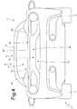
- reference numeral 1 globally denotes a car powered by means of an internal combustion engine arranged in a central position.
- the car 1 comprises a chassis, which supports the internal combustion engine, a pair of front wheels 2, and a pair of rear wheels 3.
- a passenger compartment 4 which is accessed through a pair of doors 5.
- an engine compartment 6 (partially illustrated in figures 2 , 3 and 4 ) which houses the internal combustion engine.
- the chassis is covered by a car body 7 which comprises, among other things, the doors 5, a transparent windscreen 8 which delimits the passenger compartment 4 at the front and a roof 9 that delimits the passenger compartment 4 on the upper side.
- a rear spoiler 10 (illustrated in figures 2 , 3 and 4 ) which is a continuation of the car body 7.
- the car body 7 comprises a rear panel system 11 (illustrated in figures 2 , 3 and 4 ), which joins the roof 9 to the rear area, closes the engine compartment 6 at the top and ends in correspondence with the rear spoiler 10.
- the rear spoiler 10 is integral with the car body 7, constitutes a seamless continuation of the car body 7, is arranged in a rear position and projects from the outline of the car body 7 to deflect the air flow upwards so that the air flow skims over an upper surface 12 of said rear spoiler 10.
- the rear spoiler 10 comprises a through aerodynamic duct 13 which starts in an inlet opening 14 arranged in correspondence with an initial (front) end of the rear spoiler 10 and ends in an outlet opening 15 arranged in correspondence with a final (rear) end of the rear spoiler 10 so that (as is clearly illustrated in figure 5 ) a part of the air flow hitting the rear spoiler 10 flows above the rear spoiler 10 skimming over the upper surface 12 of said rear spoiler 10 and the remaining part of the air flow hitting the rear spoiler 10 flows through the rear spoiler 10 crossing the aerodynamic duct 13.
- the rear spoiler 10 comprises a single aerodynamic duct 13; according to a different and perfectly equivalent embodiment, the rear spoiler 10 comprises two or three aerodynamic ducts 13 arranged side by side and separated from one another by a corresponding dividing wall.
- the aerodynamic duct 13 has, on the inside, a narrowing 16, which locally reduces the area of the cross section (i.e., only along a short section of the length when compared to the entire length of the aerodynamic duct 13).
- the area of the cross section of the aerodynamic duct 13 is substantially constant along the entire length of the aerodynamic duct 13 with the sole exception of the narrowing 16; as a consequence, the area of the cross section of the aerodynamic duct 13 upstream of the narrowing 16 is substantially equal to the area of the cross section of the aerodynamic duct 13 downstream of the narrowing 16.
- the narrowing 16 of the aerodynamic duct 13 consists of a deflector profile 17 that projects towards the inside of the aerodynamic duct 13.
- the deflector profile 17 is movable so as to change its position on the inside of the aerodynamic duct 13; in particular, it is provided with an actuator 18 (for example an electric motor) that is mechanically connected to the deflector profile 17 so as to move the position of the deflector profile 17 on the inside of the aerodynamic duct 13 between a position of maximum incidence (and thus maximum narrowing) and a position of minimum incidence (thus of minimum narrowing).
- an actuator 18 for example an electric motor
- Changing the position of the deflector profile 17 changes the impact of the narrowing 16 in the aerodynamic duct 13 and thus changes the air flow rate through the aerodynamic duct 13 (the greater the narrowing, the lower the air flow rate through the aerodynamic duct 13) in relation to the air flow rate over the rear spoiler 10; as a consequence, by changing the position of the deflector profile 17 it is possible to increase/decrease the negative lift (i.e., the downforce) generated by the rear spoiler 10 and at the same time decrease/increase the drag generated by the rear spoiler 10. Thus, by changing the position of the deflector profile 17 it is possible to adjust (optimise) the aerodynamic action of the rear spoiler 10 in relation to the state of motion of the car 1.
- the rear spoiler 10 has a cross section of a triangular shape and has the upper surface 12 over which the air flow flowing above the rear spoiler 10 skims, a lower surface 19 which delimits the aerodynamic duct 13 on the upper side, and a rear surface 20.
- the rear panel system 11 ends in correspondence with the rear spoiler 10 and is joined without discontinuity (i.e., without any gaps and with no abrupt slope gradient variations) to a lower surface 21 of the aerodynamic duct 13.
- the rear panel system 11 has the same inclination as the lower surface 21 of the aerodynamic duct 13 at least close to the rear spoiler 10.
- the car body 7 comprises two side boards 22, which are arranged on opposite sides of the rear panel system 11 and are arranged so as to converge in order to progressively reduce the distance between them as they get closer to the rear spoiler 10.
- the two side boards 22 end in correspondence with lateral edges of the inlet opening 14 of the aerodynamic duct 13.
- the rear panel system 11 comprises a fixed panel 23 arranged in correspondence with the rear spoiler 10 and a movable panel 24 which is arranged between the roof 9 and the panel 23 and constitutes a hood of the engine compartment 6.
- the rear spoiler 10 described above achieves good aerodynamic efficiency, i.e., it has a very favourable ratio between the negative lift and the corresponding drag. This result is achieved owing to the presence of the aerodynamic duct 13 thanks to which it is possible to increase the aerodynamic recompression in correspondence with the rear panel system 11 increasing the negative lift (i.e. downforce) without any significant increase in drag.
- the aerodynamic action of the rear spoiler 10 described above can be adjusted easily, quickly and accurately by increasing or decreasing the negative lift that is generated, in real-time.
- the rear spoiler 10 described above is easy and economical to produce, in that it may be entirely made by appropriately shaping existing components of the car body 7 (i.e. without the need for any additional components other than the deflector profile 17 and the respective actuator 18 of the deflector profile 17).
Description
- The present invention relates to a car provided with a rear spoiler.
- In high-performance cars the aerodynamics are designed to generate a strong negative lift (i.e., a strong downforce) while at the same time reducing drag to a minimum. Thus, the aerodynamic efficiency of a car is measured as a function of the ratio between the negative lift and the corresponding drag: the higher this ratio, the greater the aerodynamic efficiency of the car.
- In order to increase the negative lift on the rear axle, a method known in the prior art consists of mounting a rear spoiler, i.e., an aerodynamic element projecting from the outline of the car body that deflects the air flow upwards. It is important to note that the rear spoiler is an element that extends upwards from the car body and constitutes a seamless extension of said car body; thus, the air flow is forced to bypass the rear spoiler, i.e. to pass over the rear spoiler without any possibility of passing beneath said rear spoiler.
- Alternatively, instead of mounting a rear spoiler to the car body, it is possible to mount a rear wing, which comprises at least one winged profile arranged at a certain distance from the rest of the car body and is usually supported by a central support or by two lateral supports; the air flow hits the winged profile on both its upper surface and its lower surface, generating a downforce according to the same principle of physics that explains how aeroplanes fly. However, a rear wing is a relatively bulky element and may be associated with several drawbacks (such as higher production costs, reduced rear visibility, restricted access to the rear compartment, which may house the engine or a boot) .
- Patent application
WO2014020342A1 andpatent US5346274A describe a car comprising a rear spoiler that is integral with the car body, is arranged in a rear position and projects from the outline of the car body to deflect the air flow upwards so that the air flow skims over an upper surface of said rear spoiler; the rear spoiler comprises a through aerodynamic duct which starts in an inlet opening arranged in correspondence with an initial end of the rear spoiler and ends in an outlet opening arranged in correspondence with a final end of the rear spoiler so that a part of the air flow hitting the rear spoiler flows above the rear spoiler skimming over the upper surface of said rear spoiler and the remaining part of the air flow hitting the rear spoiler flows through the rear spoiler crossing the aerodynamic duct. In particular, in patent applicationWO2014020342A1 the aerodynamic duct has a constant cross-section which remains the same along the entire length of said aerodynamic duct, while inpatent US5346274A the aerodynamic duct has a continuously variable cross-section which continuously varies along the entire length of said aerodynamic duct. - The purpose of the present invention is to provide a car provided with a rear spoiler, said car having good aerodynamic efficiency in the rear part and, at the same time, being easy and economical to produce.
- According to the present invention there is provided a car provided with a rear spoiler according to that set forth in the appended claims.
- The present invention will now be described with reference to the accompanying drawings, illustrating a nonlimiting embodiment thereof, in which:
-
figure 1 is a front perspective view of a car produced according to the present invention; -
figure 2 is a perspective view of a rear part of the car offigure 1 ; -
figure 3 is a plan view of a rear part of the car offigure 1 ; -
figure 4 is a rear view of the car offigure 1 ; and -
figure 5 is a longitudinal section along the line V-V of the car offigure 1 . - In
figure 1 ,reference numeral 1 globally denotes a car powered by means of an internal combustion engine arranged in a central position. Thecar 1 comprises a chassis, which supports the internal combustion engine, a pair offront wheels 2, and a pair ofrear wheels 3. - Between the
front wheels 2 and therear wheels 3 there is apassenger compartment 4 which is accessed through a pair ofdoors 5. Behind thepassenger compartment 4 and in a central position there is an engine compartment 6 (partially illustrated infigures 2 ,3 and4 ) which houses the internal combustion engine. - The chassis is covered by a
car body 7 which comprises, among other things, thedoors 5, atransparent windscreen 8 which delimits thepassenger compartment 4 at the front and aroof 9 that delimits thepassenger compartment 4 on the upper side. Connected to thecar body 7 is a rear spoiler 10 (illustrated infigures 2 ,3 and4 ) which is a continuation of thecar body 7. Furthermore, thecar body 7 comprises a rear panel system 11 (illustrated infigures 2 ,3 and4 ), which joins theroof 9 to the rear area, closes theengine compartment 6 at the top and ends in correspondence with therear spoiler 10. - As illustrated in
figures 2 to 5 , therear spoiler 10 is integral with thecar body 7, constitutes a seamless continuation of thecar body 7, is arranged in a rear position and projects from the outline of thecar body 7 to deflect the air flow upwards so that the air flow skims over anupper surface 12 of saidrear spoiler 10. Therear spoiler 10 comprises a throughaerodynamic duct 13 which starts in an inlet opening 14 arranged in correspondence with an initial (front) end of therear spoiler 10 and ends in an outlet opening 15 arranged in correspondence with a final (rear) end of therear spoiler 10 so that (as is clearly illustrated infigure 5 ) a part of the air flow hitting therear spoiler 10 flows above therear spoiler 10 skimming over theupper surface 12 of saidrear spoiler 10 and the remaining part of the air flow hitting therear spoiler 10 flows through therear spoiler 10 crossing theaerodynamic duct 13. - In the embodiment illustrated in the accompanying figures, the
rear spoiler 10 comprises a singleaerodynamic duct 13; according to a different and perfectly equivalent embodiment, therear spoiler 10 comprises two or threeaerodynamic ducts 13 arranged side by side and separated from one another by a corresponding dividing wall. - According to that illustrated in
figure 5 , theaerodynamic duct 13 has, on the inside, a narrowing 16, which locally reduces the area of the cross section (i.e., only along a short section of the length when compared to the entire length of the aerodynamic duct 13). According to the invention illustrated infigure 5 , the area of the cross section of theaerodynamic duct 13 is substantially constant along the entire length of theaerodynamic duct 13 with the sole exception of thenarrowing 16; as a consequence, the area of the cross section of theaerodynamic duct 13 upstream of thenarrowing 16 is substantially equal to the area of the cross section of theaerodynamic duct 13 downstream of the narrowing 16. - According to the invention illustrated in the accompanying figures, the narrowing 16 of the
aerodynamic duct 13 consists of adeflector profile 17 that projects towards the inside of theaerodynamic duct 13. According to the invention, thedeflector profile 17 is movable so as to change its position on the inside of theaerodynamic duct 13; in particular, it is provided with an actuator 18 (for example an electric motor) that is mechanically connected to thedeflector profile 17 so as to move the position of thedeflector profile 17 on the inside of theaerodynamic duct 13 between a position of maximum incidence (and thus maximum narrowing) and a position of minimum incidence (thus of minimum narrowing). Changing the position of thedeflector profile 17 changes the impact of thenarrowing 16 in theaerodynamic duct 13 and thus changes the air flow rate through the aerodynamic duct 13 (the greater the narrowing, the lower the air flow rate through the aerodynamic duct 13) in relation to the air flow rate over therear spoiler 10; as a consequence, by changing the position of thedeflector profile 17 it is possible to increase/decrease the negative lift (i.e., the downforce) generated by therear spoiler 10 and at the same time decrease/increase the drag generated by therear spoiler 10. Thus, by changing the position of thedeflector profile 17 it is possible to adjust (optimise) the aerodynamic action of therear spoiler 10 in relation to the state of motion of thecar 1. - According to that illustrated in
figure 5 , therear spoiler 10 has a cross section of a triangular shape and has theupper surface 12 over which the air flow flowing above therear spoiler 10 skims, alower surface 19 which delimits theaerodynamic duct 13 on the upper side, and arear surface 20. - According to that illustrated in
figure 5 , therear panel system 11 ends in correspondence with therear spoiler 10 and is joined without discontinuity (i.e., without any gaps and with no abrupt slope gradient variations) to alower surface 21 of theaerodynamic duct 13. Preferably, therear panel system 11 has the same inclination as thelower surface 21 of theaerodynamic duct 13 at least close to therear spoiler 10. - According to a preferred (but not binding) embodiment illustrated in
figures 2 and3 , thecar body 7 comprises twoside boards 22, which are arranged on opposite sides of therear panel system 11 and are arranged so as to converge in order to progressively reduce the distance between them as they get closer to therear spoiler 10. In particular, the twoside boards 22 end in correspondence with lateral edges of the inlet opening 14 of theaerodynamic duct 13. - According to a preferred (but not binding) embodiment illustrated in
figures 2 ,3 and5 , therear panel system 11 comprises afixed panel 23 arranged in correspondence with therear spoiler 10 and amovable panel 24 which is arranged between theroof 9 and thepanel 23 and constitutes a hood of theengine compartment 6. - Numerous advantages are achieved with the
car 1 described above. - First, the
rear spoiler 10 described above achieves good aerodynamic efficiency, i.e., it has a very favourable ratio between the negative lift and the corresponding drag. This result is achieved owing to the presence of theaerodynamic duct 13 thanks to which it is possible to increase the aerodynamic recompression in correspondence with therear panel system 11 increasing the negative lift (i.e. downforce) without any significant increase in drag. - Moreover, notwithstanding the relatively small size of the
rear spoiler 10 described above, it is capable of generating a very high negative lift force. This result is also achieved owing to the presence of theaerodynamic duct 13 thanks to which it is possible to increase the aerodynamic recompression in correspondence with therear panel system 11 increasing the negative lift (i.e. downforce) without having to increase the size of therear spoiler 10. - The aerodynamic action of the
rear spoiler 10 described above can be adjusted easily, quickly and accurately by increasing or decreasing the negative lift that is generated, in real-time. - Lastly, the
rear spoiler 10 described above is easy and economical to produce, in that it may be entirely made by appropriately shaping existing components of the car body 7 (i.e. without the need for any additional components other than thedeflector profile 17 and therespective actuator 18 of the deflector profile 17).
Claims (9)
- A car (1) comprising:a car body (7); anda rear spoiler (10), which is integral with the car body (7), is arranged in a rear position and projects from the outline of the car body (7) to deflect the air flow upwards so that the air flow skims over an upper surface (12) of said rear spoiler (10);wherein the rear spoiler (10) comprises at least one through aerodynamic duct (13), which starts in an inlet opening (14) arranged in correspondence with an initial end of the rear spoiler (10) and ends in an outlet opening (15) arranged in correspondence with a final end of the rear spoiler (10), so that a part of the air flow hitting the rear spoiler (10) flows above the rear spoiler (10) skimming over the upper surface (12) of said rear spoiler (10) and the remaining part of the air flow hitting the rear spoiler (10) flows through the rear spoiler (10) crossing the aerodynamic duct (13); the car (1) is characterised in that:the aerodynamic duct (13) has, on the inside, a narrowing (16), which is arranged in a central position along the aerodynamic duct (13) and reduces the area of the cross section locally, i.e. only along a short section of the length when compared to the entire length of the aerodynamic duct (13);the area of the cross section of the aerodynamic duct (13) is substantially constant along the entire extension of the aerodynamic duct (13), with the sole exception of the narrowing (16), so that the area of the cross section of the aerodynamic duct (13) upstream of the narrowing (16) is equal to the area of the cross section of the aerodynamic duct (13) downstream of the narrowing (16);the narrowing (16) consists of a deflector profile (17) that projects towards the inside of the aerodynamic duct (13); andthe deflector profile (17) is movable so as to change its position on the inside of the aerodynamic duct (13).
- A car (1) according to claim 1, wherein an actuator (18) is provided, which is mechanically connected to the deflector profile (17) so as to move the position of the deflector profile (17) on the inside of the aerodynamic duct (13) .
- A car (1) according to claim 1 and 2, wherein the rear spoiler (10) has a cross section with a triangular shape and has the upper surface (12), over which the air flow flowing above the rear spoiler (10) skims, a lower surface (18), which delimits the aerodynamic duct (13) on the upper side, and a rear surface (20).
- A car (1) according to claim 1, 2 or 3, wherein the car body (7) comprises:a roof (9), which delimits a passenger compartment (4) on the upper side; anda rear panel system (11), which joins the roof (9) to the rear area, ends in correspondence with the rear spoiler (10), and is joined, without discontinuity, to a lower surface (21) of the aerodynamic duct (13) .
- A car (1) according to claim 4, wherein the rear panel system (11) has the same inclination as the lower surface (21) of the aerodynamic duct (13) at least close to the rear spoiler (10).
- A car (1) according to claim 4 or 5, wherein the car body (7) comprises two side boards (22), which are arranged on opposite sides of the rear panel system (11) and are arranged so as to converge in order to progressively reduce the distance between them as they get closer to the rear spoiler (10).
- A car (1) according to claim 6, wherein the two side boards (22) end in correspondence with lateral edges of the inlet opening (14) of the aerodynamic duct (13) .
- A car (1) according to one of the claims from 4 to 7, wherein the rear panel system (11) comprises a first fixed panel (23), which is arranged in correspondence with the rear spoiler (10), and a second movable panel (24), which is arranged between the roof (9) and the first panel (23).
- A car (1) according to claim 8, wherein:at least one engine compartment (6) is provided, which houses an engine and is arranged behind the passenger compartment (4); andthe second panel (24) makes up a hood of the engine compartment (6).
Applications Claiming Priority (1)
| Application Number | Priority Date | Filing Date | Title |
|---|---|---|---|
| ITBO20150084 | 2015-02-19 |
Publications (2)
| Publication Number | Publication Date |
|---|---|
| EP3059146A1 EP3059146A1 (en) | 2016-08-24 |
| EP3059146B1 true EP3059146B1 (en) | 2020-09-09 |
Family
ID=52727217
Family Applications (1)
| Application Number | Title | Priority Date | Filing Date |
|---|---|---|---|
| EP16156157.6A Active EP3059146B1 (en) | 2015-02-19 | 2016-02-17 | Car provided with a rear spoiler |
Country Status (2)
| Country | Link |
|---|---|
| US (1) | US9580118B2 (en) |
| EP (1) | EP3059146B1 (en) |
Families Citing this family (8)
| Publication number | Priority date | Publication date | Assignee | Title |
|---|---|---|---|---|
| US10351181B2 (en) * | 2015-03-18 | 2019-07-16 | Honda Motor Co., Ltd. | Apparatus and methods for manipulating airflow around and through a vehicle |
| US9828044B2 (en) * | 2015-09-25 | 2017-11-28 | GM Global Technology Operations LLC | Feedback control of vehicle aerodynamics |
| USD867240S1 (en) * | 2017-03-01 | 2019-11-19 | Dr. Ing. H.C. F. Porsche Aktiengesellschaft | Spoiler for motor vehicle |
| IT201700074554A1 (en) * | 2017-07-04 | 2019-01-04 | Ferrari Spa | CAR PROVIDED WITH AN ADJUSTABLE AERODYNAMIC APPENDIX DISPLACED IN BACK POSITION |
| CA185738S (en) * | 2018-07-26 | 2019-12-27 | Ferrari Spa | Car |
| CA187973S (en) * | 2018-12-13 | 2020-07-30 | Ferrari Spa | Car |
| USD927379S1 (en) * | 2019-03-15 | 2021-08-10 | Ferrari S.P.A. | Front part of a vehicle or toy vehicle |
| CL2020000174S1 (en) * | 2019-07-22 | 2020-06-19 | Ferrari Spa | Car. |
Family Cites Families (16)
| Publication number | Priority date | Publication date | Assignee | Title |
|---|---|---|---|---|
| DE2737638A1 (en) * | 1977-08-20 | 1979-03-01 | Volkswagenwerk Ag | VEHICLE TAIL |
| JPH03125677A (en) * | 1989-10-12 | 1991-05-29 | Marushiyou Sangyo:Kk | Air spoiler |
| JPH082062Y2 (en) * | 1989-12-28 | 1996-01-24 | 三菱自動車工業株式会社 | Movable air spoiler for vehicle |
| US5199762A (en) * | 1991-12-02 | 1993-04-06 | Scheele Rick L | Square-backed vehicle air foil system |
| US5282560A (en) * | 1993-04-26 | 1994-02-01 | Ford Motor Company | Luggage rack with wind noise reducer |
| US5346274A (en) * | 1993-07-16 | 1994-09-13 | General Motors Corporation | Spoiler to rear deck lid assembly |
| US5688020A (en) * | 1994-11-14 | 1997-11-18 | Burg; Donald E. | Tailgate mounted drag reducing aerostabilizer |
| US6273488B1 (en) * | 1999-05-03 | 2001-08-14 | Guardian Industries Corporation | System and method for removing liquid from rear window of a vehicle |
| DE102004004360B4 (en) * | 2004-01-29 | 2007-01-25 | Dr.Ing.H.C. F. Porsche Ag | Motor vehicle with a louver |
| DE102004041720A1 (en) * | 2004-08-28 | 2006-03-02 | Dr.Ing.H.C. F. Porsche Ag | Rear-side spoiler for a full-tail motor vehicle |
| US7175229B2 (en) * | 2005-05-20 | 2007-02-13 | Martin Lee Garcia | Vehicle spoiler with spinner mechanism |
| US20060290169A1 (en) * | 2005-06-27 | 2006-12-28 | Mazda Motor Corporation | Vehicle rear body structure |
| JP5803185B2 (en) * | 2011-03-23 | 2015-11-04 | アイシン精機株式会社 | Rear spoiler |
| DE102011053500B4 (en) * | 2011-09-12 | 2022-02-03 | Dr. Ing. H.C. F. Porsche Aktiengesellschaft | Cooling device for a motor vehicle with an extendable rear spoiler and an intercooler |
| ITBO20120089A1 (en) * | 2012-02-24 | 2013-08-25 | Ferrari Spa | METHOD OF CONTROL OF A HIGH PERFORMANCE ROAD VEHICLE PROVIDED WITH A REAR BULB WITH AT LEAST ONE MOBILE WING ELEMENT |
| GB2504697B (en) | 2012-08-03 | 2019-09-11 | Aston Martin Lagonda Ltd | Methods and apparatus for forming workpiece components |
-
2016
- 2016-02-17 EP EP16156157.6A patent/EP3059146B1/en active Active
- 2016-02-18 US US15/046,561 patent/US9580118B2/en active Active
Non-Patent Citations (1)
| Title |
|---|
| None * |
Also Published As
| Publication number | Publication date |
|---|---|
| US20160244106A1 (en) | 2016-08-25 |
| EP3059146A1 (en) | 2016-08-24 |
| US9580118B2 (en) | 2017-02-28 |
Similar Documents
| Publication | Publication Date | Title |
|---|---|---|
| EP3059146B1 (en) | Car provided with a rear spoiler | |
| EP3517414B1 (en) | Car having an enhanced front aerodynamic load | |
| US7497502B2 (en) | Mini skirt aerodynamic fairing device for reducing the aerodynamic drag of ground vehicles | |
| EP3424807B1 (en) | Car provided with an adjustable aerodynamic appendage arranged in a rear position | |
| US7226117B2 (en) | Rear-end spoiler for a full-rear vehicle | |
| US8382194B2 (en) | Outboard wake stabilization device and method for reducing the aerodynamic drag of ground vehicles | |
| US9481409B2 (en) | Underbody panelling | |
| US20140097638A1 (en) | Active aero diffuser | |
| US20110204677A1 (en) | Dam skirt aerodynamic fairing device | |
| AU2011378813B2 (en) | Truck fairing | |
| JP7372326B2 (en) | motorcycle | |
| CN212022801U (en) | Aerodynamic device, hood device and grille for a vehicle, and vehicle | |
| CN112478003B (en) | Motor vehicle with rear spoiler and movable deflector for adjusting the rear spoiler | |
| US20130168999A1 (en) | Vehicle airstream deflector and related method | |
| US9688321B2 (en) | Downforce generation system for a vehicle | |
| CN112478004B (en) | Motor vehicle with rear spoiler and pneumatic element for increasing the pneumatic efficiency of the rear spoiler | |
| EP2679474B1 (en) | Car with an underbody provided with an aerodynamic diffuser | |
| CN202987305U (en) | Extensible bottom guide plate | |
| US20170008577A1 (en) | Bluff body adaptive wake reduction system | |
| US20180354564A1 (en) | Wing for vehicles, process for its control and motor vehicle comprising this wing | |
| GB2508357A (en) | Aerodynamic drag reduction device for vehicle rear | |
| US11891126B2 (en) | Active rear diffuser for vehicle | |
| EP2607132A1 (en) | Air intake assembly | |
| WO2022243825A1 (en) | A system and method for creating vehicular downforce | |
| GB2582224A (en) | Aerodynamic apparatus |
Legal Events
| Date | Code | Title | Description |
|---|---|---|---|
| PUAI | Public reference made under article 153(3) epc to a published international application that has entered the european phase |
Free format text: ORIGINAL CODE: 0009012 |
|
| AK | Designated contracting states |
Kind code of ref document: A1 Designated state(s): AL AT BE BG CH CY CZ DE DK EE ES FI FR GB GR HR HU IE IS IT LI LT LU LV MC MK MT NL NO PL PT RO RS SE SI SK SM TR |
|
| AX | Request for extension of the european patent |
Extension state: BA ME |
|
| STAA | Information on the status of an ep patent application or granted ep patent |
Free format text: STATUS: REQUEST FOR EXAMINATION WAS MADE |
|
| 17P | Request for examination filed |
Effective date: 20161229 |
|
| GRAP | Despatch of communication of intention to grant a patent |
Free format text: ORIGINAL CODE: EPIDOSNIGR1 |
|
| STAA | Information on the status of an ep patent application or granted ep patent |
Free format text: STATUS: GRANT OF PATENT IS INTENDED |
|
| INTG | Intention to grant announced |
Effective date: 20200402 |
|
| RIC1 | Information provided on ipc code assigned before grant |
Ipc: B62D 37/02 20060101ALI20200323BHEP Ipc: B62D 35/00 20060101AFI20200323BHEP |
|
| GRAS | Grant fee paid |
Free format text: ORIGINAL CODE: EPIDOSNIGR3 |
|
| GRAA | (expected) grant |
Free format text: ORIGINAL CODE: 0009210 |
|
| STAA | Information on the status of an ep patent application or granted ep patent |
Free format text: STATUS: THE PATENT HAS BEEN GRANTED |
|
| AK | Designated contracting states |
Kind code of ref document: B1 Designated state(s): AL AT BE BG CH CY CZ DE DK EE ES FI FR GB GR HR HU IE IS IT LI LT LU LV MC MK MT NL NO PL PT RO RS SE SI SK SM TR |
|
| REG | Reference to a national code |
Ref country code: GB Ref legal event code: FG4D |
|
| REG | Reference to a national code |
Ref country code: AT Ref legal event code: REF Ref document number: 1311254 Country of ref document: AT Kind code of ref document: T Effective date: 20200915 Ref country code: CH Ref legal event code: EP |
|
| REG | Reference to a national code |
Ref country code: IE Ref legal event code: FG4D |
|
| REG | Reference to a national code |
Ref country code: DE Ref legal event code: R096 Ref document number: 602016043548 Country of ref document: DE |
|
| REG | Reference to a national code |
Ref country code: LT Ref legal event code: MG4D |
|
| PG25 | Lapsed in a contracting state [announced via postgrant information from national office to epo] |
Ref country code: BG Free format text: LAPSE BECAUSE OF FAILURE TO SUBMIT A TRANSLATION OF THE DESCRIPTION OR TO PAY THE FEE WITHIN THE PRESCRIBED TIME-LIMIT Effective date: 20201209 Ref country code: LT Free format text: LAPSE BECAUSE OF FAILURE TO SUBMIT A TRANSLATION OF THE DESCRIPTION OR TO PAY THE FEE WITHIN THE PRESCRIBED TIME-LIMIT Effective date: 20200909 Ref country code: GR Free format text: LAPSE BECAUSE OF FAILURE TO SUBMIT A TRANSLATION OF THE DESCRIPTION OR TO PAY THE FEE WITHIN THE PRESCRIBED TIME-LIMIT Effective date: 20201210 Ref country code: FI Free format text: LAPSE BECAUSE OF FAILURE TO SUBMIT A TRANSLATION OF THE DESCRIPTION OR TO PAY THE FEE WITHIN THE PRESCRIBED TIME-LIMIT Effective date: 20200909 Ref country code: HR Free format text: LAPSE BECAUSE OF FAILURE TO SUBMIT A TRANSLATION OF THE DESCRIPTION OR TO PAY THE FEE WITHIN THE PRESCRIBED TIME-LIMIT Effective date: 20200909 Ref country code: NO Free format text: LAPSE BECAUSE OF FAILURE TO SUBMIT A TRANSLATION OF THE DESCRIPTION OR TO PAY THE FEE WITHIN THE PRESCRIBED TIME-LIMIT Effective date: 20201209 Ref country code: SE Free format text: LAPSE BECAUSE OF FAILURE TO SUBMIT A TRANSLATION OF THE DESCRIPTION OR TO PAY THE FEE WITHIN THE PRESCRIBED TIME-LIMIT Effective date: 20200909 |
|
| REG | Reference to a national code |
Ref country code: AT Ref legal event code: MK05 Ref document number: 1311254 Country of ref document: AT Kind code of ref document: T Effective date: 20200909 |
|
| REG | Reference to a national code |
Ref country code: NL Ref legal event code: MP Effective date: 20200909 |
|
| PG25 | Lapsed in a contracting state [announced via postgrant information from national office to epo] |
Ref country code: RS Free format text: LAPSE BECAUSE OF FAILURE TO SUBMIT A TRANSLATION OF THE DESCRIPTION OR TO PAY THE FEE WITHIN THE PRESCRIBED TIME-LIMIT Effective date: 20200909 Ref country code: PL Free format text: LAPSE BECAUSE OF FAILURE TO SUBMIT A TRANSLATION OF THE DESCRIPTION OR TO PAY THE FEE WITHIN THE PRESCRIBED TIME-LIMIT Effective date: 20200909 Ref country code: LV Free format text: LAPSE BECAUSE OF FAILURE TO SUBMIT A TRANSLATION OF THE DESCRIPTION OR TO PAY THE FEE WITHIN THE PRESCRIBED TIME-LIMIT Effective date: 20200909 |
|
| PG25 | Lapsed in a contracting state [announced via postgrant information from national office to epo] |
Ref country code: NL Free format text: LAPSE BECAUSE OF FAILURE TO SUBMIT A TRANSLATION OF THE DESCRIPTION OR TO PAY THE FEE WITHIN THE PRESCRIBED TIME-LIMIT Effective date: 20200909 Ref country code: RO Free format text: LAPSE BECAUSE OF FAILURE TO SUBMIT A TRANSLATION OF THE DESCRIPTION OR TO PAY THE FEE WITHIN THE PRESCRIBED TIME-LIMIT Effective date: 20200909 Ref country code: PT Free format text: LAPSE BECAUSE OF FAILURE TO SUBMIT A TRANSLATION OF THE DESCRIPTION OR TO PAY THE FEE WITHIN THE PRESCRIBED TIME-LIMIT Effective date: 20210111 Ref country code: SM Free format text: LAPSE BECAUSE OF FAILURE TO SUBMIT A TRANSLATION OF THE DESCRIPTION OR TO PAY THE FEE WITHIN THE PRESCRIBED TIME-LIMIT Effective date: 20200909 Ref country code: EE Free format text: LAPSE BECAUSE OF FAILURE TO SUBMIT A TRANSLATION OF THE DESCRIPTION OR TO PAY THE FEE WITHIN THE PRESCRIBED TIME-LIMIT Effective date: 20200909 Ref country code: CZ Free format text: LAPSE BECAUSE OF FAILURE TO SUBMIT A TRANSLATION OF THE DESCRIPTION OR TO PAY THE FEE WITHIN THE PRESCRIBED TIME-LIMIT Effective date: 20200909 |
|
| PG25 | Lapsed in a contracting state [announced via postgrant information from national office to epo] |
Ref country code: AL Free format text: LAPSE BECAUSE OF FAILURE TO SUBMIT A TRANSLATION OF THE DESCRIPTION OR TO PAY THE FEE WITHIN THE PRESCRIBED TIME-LIMIT Effective date: 20200909 Ref country code: AT Free format text: LAPSE BECAUSE OF FAILURE TO SUBMIT A TRANSLATION OF THE DESCRIPTION OR TO PAY THE FEE WITHIN THE PRESCRIBED TIME-LIMIT Effective date: 20200909 Ref country code: ES Free format text: LAPSE BECAUSE OF FAILURE TO SUBMIT A TRANSLATION OF THE DESCRIPTION OR TO PAY THE FEE WITHIN THE PRESCRIBED TIME-LIMIT Effective date: 20200909 Ref country code: IS Free format text: LAPSE BECAUSE OF FAILURE TO SUBMIT A TRANSLATION OF THE DESCRIPTION OR TO PAY THE FEE WITHIN THE PRESCRIBED TIME-LIMIT Effective date: 20210109 |
|
| REG | Reference to a national code |
Ref country code: DE Ref legal event code: R097 Ref document number: 602016043548 Country of ref document: DE |
|
| PG25 | Lapsed in a contracting state [announced via postgrant information from national office to epo] |
Ref country code: SK Free format text: LAPSE BECAUSE OF FAILURE TO SUBMIT A TRANSLATION OF THE DESCRIPTION OR TO PAY THE FEE WITHIN THE PRESCRIBED TIME-LIMIT Effective date: 20200909 |
|
| PLBE | No opposition filed within time limit |
Free format text: ORIGINAL CODE: 0009261 |
|
| STAA | Information on the status of an ep patent application or granted ep patent |
Free format text: STATUS: NO OPPOSITION FILED WITHIN TIME LIMIT |
|
| 26N | No opposition filed |
Effective date: 20210610 |
|
| PG25 | Lapsed in a contracting state [announced via postgrant information from national office to epo] |
Ref country code: SI Free format text: LAPSE BECAUSE OF FAILURE TO SUBMIT A TRANSLATION OF THE DESCRIPTION OR TO PAY THE FEE WITHIN THE PRESCRIBED TIME-LIMIT Effective date: 20200909 Ref country code: DK Free format text: LAPSE BECAUSE OF FAILURE TO SUBMIT A TRANSLATION OF THE DESCRIPTION OR TO PAY THE FEE WITHIN THE PRESCRIBED TIME-LIMIT Effective date: 20200909 |
|
| PG25 | Lapsed in a contracting state [announced via postgrant information from national office to epo] |
Ref country code: MC Free format text: LAPSE BECAUSE OF FAILURE TO SUBMIT A TRANSLATION OF THE DESCRIPTION OR TO PAY THE FEE WITHIN THE PRESCRIBED TIME-LIMIT Effective date: 20200909 |
|
| REG | Reference to a national code |
Ref country code: BE Ref legal event code: MM Effective date: 20210228 |
|
| PG25 | Lapsed in a contracting state [announced via postgrant information from national office to epo] |
Ref country code: LU Free format text: LAPSE BECAUSE OF NON-PAYMENT OF DUE FEES Effective date: 20210217 Ref country code: LI Free format text: LAPSE BECAUSE OF NON-PAYMENT OF DUE FEES Effective date: 20210228 Ref country code: CH Free format text: LAPSE BECAUSE OF NON-PAYMENT OF DUE FEES Effective date: 20210228 |
|
| PG25 | Lapsed in a contracting state [announced via postgrant information from national office to epo] |
Ref country code: IE Free format text: LAPSE BECAUSE OF NON-PAYMENT OF DUE FEES Effective date: 20210217 |
|
| PG25 | Lapsed in a contracting state [announced via postgrant information from national office to epo] |
Ref country code: BE Free format text: LAPSE BECAUSE OF NON-PAYMENT OF DUE FEES Effective date: 20210228 |
|
| PGFP | Annual fee paid to national office [announced via postgrant information from national office to epo] |
Ref country code: FR Payment date: 20230223 Year of fee payment: 8 |
|
| PG25 | Lapsed in a contracting state [announced via postgrant information from national office to epo] |
Ref country code: HU Free format text: LAPSE BECAUSE OF FAILURE TO SUBMIT A TRANSLATION OF THE DESCRIPTION OR TO PAY THE FEE WITHIN THE PRESCRIBED TIME-LIMIT; INVALID AB INITIO Effective date: 20160217 |
|
| PGFP | Annual fee paid to national office [announced via postgrant information from national office to epo] |
Ref country code: IT Payment date: 20230213 Year of fee payment: 8 Ref country code: GB Payment date: 20230214 Year of fee payment: 8 Ref country code: DE Payment date: 20230227 Year of fee payment: 8 |
|
| PG25 | Lapsed in a contracting state [announced via postgrant information from national office to epo] |
Ref country code: CY Free format text: LAPSE BECAUSE OF FAILURE TO SUBMIT A TRANSLATION OF THE DESCRIPTION OR TO PAY THE FEE WITHIN THE PRESCRIBED TIME-LIMIT Effective date: 20200909 |
|
| P01 | Opt-out of the competence of the unified patent court (upc) registered |
Effective date: 20230525 |