EP3059132A1 - Smart load cell - Google Patents
Smart load cell Download PDFInfo
- Publication number
- EP3059132A1 EP3059132A1 EP16154041.4A EP16154041A EP3059132A1 EP 3059132 A1 EP3059132 A1 EP 3059132A1 EP 16154041 A EP16154041 A EP 16154041A EP 3059132 A1 EP3059132 A1 EP 3059132A1
- Authority
- EP
- European Patent Office
- Prior art keywords
- load cell
- microcontroller
- electromechanical actuator
- actuator
- electromechanical
- Prior art date
- Legal status (The legal status is an assumption and is not a legal conclusion. Google has not performed a legal analysis and makes no representation as to the accuracy of the status listed.)
- Granted
Links
Images


Classifications
-
- G—PHYSICS
- G01—MEASURING; TESTING
- G01L—MEASURING FORCE, STRESS, TORQUE, WORK, MECHANICAL POWER, MECHANICAL EFFICIENCY, OR FLUID PRESSURE
- G01L5/00—Apparatus for, or methods of, measuring force, work, mechanical power, or torque, specially adapted for specific purposes
- G01L5/22—Apparatus for, or methods of, measuring force, work, mechanical power, or torque, specially adapted for specific purposes for measuring the force applied to control members, e.g. control members of vehicles, triggers
- G01L5/225—Apparatus for, or methods of, measuring force, work, mechanical power, or torque, specially adapted for specific purposes for measuring the force applied to control members, e.g. control members of vehicles, triggers to foot actuated controls, e.g. brake pedals
-
- B—PERFORMING OPERATIONS; TRANSPORTING
- B60—VEHICLES IN GENERAL
- B60T—VEHICLE BRAKE CONTROL SYSTEMS OR PARTS THEREOF; BRAKE CONTROL SYSTEMS OR PARTS THEREOF, IN GENERAL; ARRANGEMENT OF BRAKING ELEMENTS ON VEHICLES IN GENERAL; PORTABLE DEVICES FOR PREVENTING UNWANTED MOVEMENT OF VEHICLES; VEHICLE MODIFICATIONS TO FACILITATE COOLING OF BRAKES
- B60T17/00—Component parts, details, or accessories of power brake systems not covered by groups B60T8/00, B60T13/00 or B60T15/00, or presenting other characteristic features
- B60T17/18—Safety devices; Monitoring
- B60T17/22—Devices for monitoring or checking brake systems; Signal devices
- B60T17/221—Procedure or apparatus for checking or keeping in a correct functioning condition of brake systems
-
- B—PERFORMING OPERATIONS; TRANSPORTING
- B64—AIRCRAFT; AVIATION; COSMONAUTICS
- B64C—AEROPLANES; HELICOPTERS
- B64C25/00—Alighting gear
- B64C25/32—Alighting gear characterised by elements which contact the ground or similar surface
- B64C25/42—Arrangement or adaptation of brakes
- B64C25/44—Actuating mechanisms
-
- F—MECHANICAL ENGINEERING; LIGHTING; HEATING; WEAPONS; BLASTING
- F16—ENGINEERING ELEMENTS AND UNITS; GENERAL MEASURES FOR PRODUCING AND MAINTAINING EFFECTIVE FUNCTIONING OF MACHINES OR INSTALLATIONS; THERMAL INSULATION IN GENERAL
- F16D—COUPLINGS FOR TRANSMITTING ROTATION; CLUTCHES; BRAKES
- F16D66/00—Arrangements for monitoring working conditions, e.g. wear, temperature
-
- G—PHYSICS
- G01—MEASURING; TESTING
- G01K—MEASURING TEMPERATURE; MEASURING QUANTITY OF HEAT; THERMALLY-SENSITIVE ELEMENTS NOT OTHERWISE PROVIDED FOR
- G01K13/00—Thermometers specially adapted for specific purposes
-
- G—PHYSICS
- G01—MEASURING; TESTING
- G01L—MEASURING FORCE, STRESS, TORQUE, WORK, MECHANICAL POWER, MECHANICAL EFFICIENCY, OR FLUID PRESSURE
- G01L25/00—Testing or calibrating of apparatus for measuring force, torque, work, mechanical power, or mechanical efficiency
-
- B—PERFORMING OPERATIONS; TRANSPORTING
- B60—VEHICLES IN GENERAL
- B60T—VEHICLE BRAKE CONTROL SYSTEMS OR PARTS THEREOF; BRAKE CONTROL SYSTEMS OR PARTS THEREOF, IN GENERAL; ARRANGEMENT OF BRAKING ELEMENTS ON VEHICLES IN GENERAL; PORTABLE DEVICES FOR PREVENTING UNWANTED MOVEMENT OF VEHICLES; VEHICLE MODIFICATIONS TO FACILITATE COOLING OF BRAKES
- B60T2250/00—Monitoring, detecting, estimating vehicle conditions
- B60T2250/06—Sensor zero-point adjustment; Offset compensation
-
- F—MECHANICAL ENGINEERING; LIGHTING; HEATING; WEAPONS; BLASTING
- F16—ENGINEERING ELEMENTS AND UNITS; GENERAL MEASURES FOR PRODUCING AND MAINTAINING EFFECTIVE FUNCTIONING OF MACHINES OR INSTALLATIONS; THERMAL INSULATION IN GENERAL
- F16D—COUPLINGS FOR TRANSMITTING ROTATION; CLUTCHES; BRAKES
- F16D66/00—Arrangements for monitoring working conditions, e.g. wear, temperature
- F16D2066/005—Force, torque, stress or strain
Definitions
- the present disclosure relates generally to aircraft wheel assemblies and, more specifically, to electromechanical actuator systems for aircraft wheel assemblies.
- electromechanical actuators are controlled by an electric brake actuator controller.
- electromechanical actuators frequently include load cells which provide feedback and are distinct from and independent of the actuator. These stand-alone load cells are calibrated manually, by adding individual resistors to the load cells. Such calibration requires significant time, labor, and can only be performed at actuator assembly time.
- An electromechanical actuator system in accordance with various embodiments may comprise an actuator and a load cell coupled to the actuator and comprising a circuit board, a strain gage, a microcontroller, a bridge, and an output drive circuit in communication with the microcontroller.
- the load cell may comprise two strain gages. The two strain gages may be positioned apart from each other at approximately 180 degrees along a circumference of the outer surface of the housing.
- the load cell may further comprise an output drive circuit.
- the microcontroller may be positioned between the output drive circuit and a Wheatstone bridge.
- the output drive circuit may provide a signal to an electric brake actuator controller.
- the output drive circuit may comprise a serial interface.
- the load cell may further comprise a sense resistor in series with the Wheatstone bridge. The load cell may receive a voltage from the electric brake actuator controller
- a method for controlling an electromechanical brake actuator in accordance with various embodiments may comprise calibrating a load cell of an electromechanical actuator system, wherein the load cell comprises a flexible circuit board coupled to a housing and having at least one strain gage, a microcontroller, a bridge, and an output drive circuit in communication with the microcontroller, and transmitting an output signal from the output drive circuit to an electric brake actuator controller.
- the method may further comprise transmitting a command signal from the electric brake actuator controller to an electromechanical brake actuator.
- the step of calibrating the load cell may comprise determining a minimum bridge value at a zero load and determining a maximum bridge value at a maximum load.
- the load cell may be configured to receive a voltage from the electric brake actuator controller.
- the output drive circuit may communicate with the electric brake actuator controller via a serial interface.
- the load cell may further comprise a sense resistor in series with the bridge.
- Wheel and brake system 10 may comprise, for example, a brake assembly 11.
- brake assembly 11 may be coupled to an axle of a wheel 12.
- brake assembly 11 consists of rotors and stators that are compressed together by brake actuator 36 to reduce the speed of an aircraft.
- brake assembly 11 may comprise a brake stack 27 and a brake actuator 36.
- brake stack 27 may comprise components that interface with both the rotating rotors and the wheel axle through torque tube 16.
- Brake assembly 11 may further comprise, for example, one or more brake actuators 36.
- brake actuators 36 may be configured such that in response to an operator activating a control (e.g., depressing a brake pedal), brake actuators 36 laterally compress brake stack 27 which, in turn, resists rotation of wheel 12 and thus reduces the speed of the aircraft.
- Brake actuator 36 may comprise, for example, an electromechanical brake actuator. In various embodiments, a predetermined level of actuation force is applied to brake stack 27 by brake actuator 36. In various embodiments, brake actuator 36 may comprise a hydraulic actuator. In embodiments where brake actuator 36 is a hydraulic actuator, brake actuator 36 may be actuated by hydraulic pressure. In further embodiments, brake actuator 36 may comprise a hybrid electromechanical-hydraulic actuator. Any type of actuator is within the scope of the present disclosure.
- brake actuator 36 comprises a brake actuator housing 37.
- Brake actuator housing 37 may surround and house at least a portion of the components of brake actuator 36.
- Brake actuator housing 37 comprises an outer surface 39.
- strain gages that comprise a Wheatstone bridge 200 are affixed to outer surface 39 of brake actuator housing 37 to measure tension.
- outer surface 39 may comprise a channel 41 into which Wheatstone bridge 200 may be positioned.
- Wheatstone bridge 200 may reside internal to brake actuator 36 and measure a compressive load. Any manner of affixing Wheatstone bridge 200 to any part of brake actuator 36 to measure tension or compressive forces is within the scope of the present disclosure.
- Wheatstone bridge 200 comprises a flexible printed circuit board 254.
- Wheatstone bridge 200 comprises two strain gages 252 positioned apart from one another.
- two strain gages 252 may be positioned approximately 180 degrees from each other along the circumference of outer surface 39 of brake actuator housing 37.
- any number and positioning of strain gages 252 is with the scope of the present disclosure.
- a smart load cell 300 is formed by the combination of Wheatstone bridge 200, including one or more strain gages 252, connected (e.g., by flexible printed circuit board 254) and a printed circuit board 38 comprising a microcontroller and an output drive circuit.
- signal conditioning component 360 may comprise a component configured to make the output of bridge 200 suitable for processing by another component of smart load cell 300.
- signal conditioning component 360 may comprise a filter, an amplifier, or any other component capable of conditioning the output of bridge 200 in a desired manner.
- Smart load cell 300 may further comprise, for example, a microcontroller 366.
- Microcontroller 366 may be configured to operate as a data acquisition and digital signal processing system.
- microcontroller 366 may receive data from bridge 200 via signal conditioning unit 360. Such data may be processed, stored, and analyzed by microcontroller 366.
- microcontroller 366 comprises an analog to digital converter 374A, which may be configured to receive analog data from bridge 200 and convert it to digital data for processing by microcontroller 366.
- microcontroller 366 comprises an output drive circuit.
- microcontroller 366 may comprise an output drive circuit 368A which comprises an analog drive circuit 370A.
- microcontroller 366 provides data from a digital analog converter (within microcontroller 366) to analog drive circuit 370A, which may transmit the analog data to EBAC 372.
- Analog drive circuit 370A may comprise, for example, a 4 milliamp to 20 milliamp drive circuit.
- microcontroller 366 comprises an output drive circuit 368B which comprises a digital drive circuit 370B.
- microcontroller 366 provides digital data to EBAC 372.
- digital drive circuit 370B may utilize a serial communication protocol, such as, for example, an RS232 or RS485 protocol.
- Microcontroller 366 may, for example, provide a cleaner and/or more accurate output signal to EBAC 372 than an unconditioned analog bridge 200 signal. Further, microcontroller 366 may be capable of bidirectional communication with EBAC 372. Bidirectional communication between microcontroller 366 and EBAC 372 may, for example, allow for built in testing to evaluate the health of EBAC 372 and various sensors, detection and correction of error conditions, among others.
- additional components and/or sensors such as, for example, an accelerometer 376, may be added to smart load cell 300 in communication with microcontroller 366.
- accelerometer 376 may allow microcontroller 366 to monitor the health and performance of smart load cell 300, including through the use of built in testing processes.
- Smart load cell 300 may further comprise, for example, a temperature sensing element 364.
- data may be transmitted from bridge 200 to temperature sensing element 364.
- Temperature sensing element 364 may transmit data to microcontroller 366.
- data from temperature sensing element 364 may be sent to a signal conditioning component 362 (similar to signal conditioning component 360) prior to microcontroller 366.
- microcontroller 366 comprises an analog to digital converter 374B, which may be configured to receive analog data from temperature sensing element 364 and convert it to digital data for processing by microcontroller 366.
- temperature sensing element 364 may allow microcontroller 366 to determine the operating temperature of brake actuator 36 by comparing data received from bridge 200 to data received from temperature sensing element 364.
- microcontroller 366 may employ a temperature compensation formula to adjust or calibrate data received from bridge 200 prior to transmitting the data to EBAC 372.
- the temperature of brake actuator 36 may increase, which can change the characteristics of strain gages 252, which in turn may affect the accuracy of data provided by strain gages 252.
- strain gauges 252 may expand axially and/or radially, thereby registering a positive strain on brake actuator housing 37.
- strain gauges 252 may contract axially and/or radially, thereby registering a negative strain on brake actuator housing 37.
- resistors and/or other components of bridge 200 may fluctuate as temperature increases or decreases. Therefore, determining the temperature of brake actuator 36 and/or brake actuator housing 37 may be beneficial in correcting and/or calibrating data received from bridge 200 by microcontroller 366.
- smart load cell 300 may further comprise a voltage reference 358.
- voltage reference 358 may receive voltage from EBAC 372. Further, voltage reference 358 may provide a fixed voltage to bridge 200 and/or microcontroller 366.
- method 400 may comprise a step 480 of calibrating the load cell.
- step 480 may comprise calibrating the load cell by determining a minimum bridge value at zero load and a maximum bridge value at maximum load.
- the zero load value may be determined by bridge 200 when brake actuator 36 is under no external load (i.e., at rest and at zero extension).
- the maximum bridge value may be determined by bridge 200 when brake actuator 36 is fully extended. The zero load value and the maximum load value may, for example, be transmitted from bridge 200 to microcontroller 366.
- the zero load trim value and maximum load trim value may be determined at any temperature.
- the zero load value and maximum load value may be determined at "room" temperature. Room temperature can be defined as the temperature of the surroundings of the aircraft when the aircraft is not in flight. Variations in the load based on temperature changes are compensated for with temperature sensing element 364.
- Method 400 may further comprise a step 482 of transmitting an output signal to an EBAC.
- microcontroller 366 may transmit a signal through an output drive circuit (such as output drive circuit 368A and/or 368B) to EBAC 372.
- microcontroller 366 may receive data from bridge 200 and adjust or calibrate the data using a temperature compensation formula. Such data may then be transmitted through the output drive circuit (such as output drive circuit 368A and/or 368B) to EBAC 372.
- method 400 further comprises a step 484 of transmitting a command signal from an EBAC.
- step 484 may comprise EBAC 372 transmitting a command signal to brake actuator 36.
- the command signal is calculating using data provided to EBAC 372 from smart load cell 300. Specifically, data transmitted from microcontroller 366 through an output drive circuit (such as output drive circuit 368A and/or 368B) may be used to calculate a command signal, which in turn is transmitted to brake actuator 36.
- the command signal activates and causes a desired displacement of brake actuator 36.
- references to "one embodiment,” “an embodiment,” “an example embodiment,” etc. indicate that the embodiment described may include a particular feature, structure, or characteristic, but every embodiment may not necessarily include the particular feature, structure, or characteristic. Moreover, such phrases are not necessarily referring to the same embodiment. Further, when a particular feature, structure, or characteristic is described in connection with an embodiment, it is submitted that it is within the knowledge of one skilled in the art to affect such feature, structure, or characteristic in connection with other embodiments whether or not explicitly described. After reading the description, it will be apparent to one skilled in the relevant art(s) how to implement the disclosure in alternative embodiments.
Landscapes
- Engineering & Computer Science (AREA)
- Mechanical Engineering (AREA)
- Physics & Mathematics (AREA)
- General Physics & Mathematics (AREA)
- General Engineering & Computer Science (AREA)
- Transportation (AREA)
- Aviation & Aerospace Engineering (AREA)
- Braking Systems And Boosters (AREA)
Abstract
Description
- The present disclosure relates generally to aircraft wheel assemblies and, more specifically, to electromechanical actuator systems for aircraft wheel assemblies.
- Conventional aircraft wheel assemblies comprise rotating and stationary stacks which stop the aircraft when compressed by electromechanical actuators. Typically, electromechanical actuators are controlled by an electric brake actuator controller. To properly account for variations in operating loads on the aircraft brake assemblies, electromechanical actuators frequently include load cells which provide feedback and are distinct from and independent of the actuator. These stand-alone load cells are calibrated manually, by adding individual resistors to the load cells. Such calibration requires significant time, labor, and can only be performed at actuator assembly time.
- An electromechanical actuator system in accordance with various embodiments may comprise an actuator and a load cell coupled to the actuator and comprising a circuit board, a strain gage, a microcontroller, a bridge, and an output drive circuit in communication with the microcontroller. The load cell may comprise two strain gages. The two strain gages may be positioned apart from each other at approximately 180 degrees along a circumference of the outer surface of the housing. The load cell may further comprise an output drive circuit. The microcontroller may be positioned between the output drive circuit and a Wheatstone bridge. The output drive circuit may provide a signal to an electric brake actuator controller. The output drive circuit may comprise a serial interface. The load cell may further comprise a sense resistor in series with the Wheatstone bridge. The load cell may receive a voltage from the electric brake actuator controller
- A method for controlling an electromechanical brake actuator in accordance with various embodiments may comprise calibrating a load cell of an electromechanical actuator system, wherein the load cell comprises a flexible circuit board coupled to a housing and having at least one strain gage, a microcontroller, a bridge, and an output drive circuit in communication with the microcontroller, and transmitting an output signal from the output drive circuit to an electric brake actuator controller. The method may further comprise transmitting a command signal from the electric brake actuator controller to an electromechanical brake actuator. The step of calibrating the load cell may comprise determining a minimum bridge value at a zero load and determining a maximum bridge value at a maximum load. The load cell may be configured to receive a voltage from the electric brake actuator controller. The output drive circuit may communicate with the electric brake actuator controller via a serial interface. The load cell may further comprise a sense resistor in series with the bridge.
- The subject matter of the present disclosure is particularly pointed out and distinctly claimed in the concluding portion of the specification. A more complete understanding of the present disclosure, however, may best be obtained by referring to the detailed description and claims when considered in connection with the drawing figures, wherein like numerals denote like elements.
-
Figure 1 illustrates a portion of an aircraft brake system in accordance with various embodiments; -
Figure 2 illustrates a perspective view of an electromechanical brake actuator housing in accordance with various embodiments; -
Figure 3 illustrates a block diagram of a smart load cell system of an electromechanical brake actuator system in accordance with various embodiments; and -
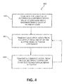
Figure 4 illustrates a flow chart depicting a method of controlling an electromechanical actuator in accordance with various embodiments. - The detailed description of embodiments herein makes reference to the accompanying drawings, which show embodiments by way of illustration. While these embodiments are described in sufficient detail to enable those skilled in the art to practice the invention, it should be understood that other embodiments may be realized and that logical and mechanical changes may be made without departing from the scope of the invention. Thus, the detailed description herein is presented for purposes of illustration only and not for limitation. For example, any reference to singular includes plural embodiments, and any reference to more than one component or step may include a singular embodiment or step. Also, any reference to attached, fixed, connected or the like may include permanent, removable, temporary, partial, full and/or any other possible attachment option.
- With reference to
Figure 1 , a portion of a wheel andbrake system 10 is illustrated. Wheel andbrake system 10 may comprise, for example, abrake assembly 11. In various embodiments,brake assembly 11 may be coupled to an axle of awheel 12. For example,brake assembly 11 consists of rotors and stators that are compressed together bybrake actuator 36 to reduce the speed of an aircraft. - In various embodiments,
brake assembly 11 may comprise abrake stack 27 and abrake actuator 36. For example,brake stack 27 may comprise components that interface with both the rotating rotors and the wheel axle throughtorque tube 16. -
Brake assembly 11 may further comprise, for example, one ormore brake actuators 36. For example,brake actuators 36 may be configured such that in response to an operator activating a control (e.g., depressing a brake pedal),brake actuators 36 laterally compressbrake stack 27 which, in turn, resists rotation ofwheel 12 and thus reduces the speed of the aircraft. -
Brake actuator 36 may comprise, for example, an electromechanical brake actuator. In various embodiments, a predetermined level of actuation force is applied tobrake stack 27 bybrake actuator 36. In various embodiments,brake actuator 36 may comprise a hydraulic actuator. In embodiments wherebrake actuator 36 is a hydraulic actuator,brake actuator 36 may be actuated by hydraulic pressure. In further embodiments,brake actuator 36 may comprise a hybrid electromechanical-hydraulic actuator. Any type of actuator is within the scope of the present disclosure. - With reference to
Figure 2 , in various embodiments,brake actuator 36 comprises abrake actuator housing 37.Brake actuator housing 37 may surround and house at least a portion of the components ofbrake actuator 36.Brake actuator housing 37 comprises anouter surface 39. In various embodiments, strain gages that comprise a Wheatstonebridge 200 are affixed toouter surface 39 ofbrake actuator housing 37 to measure tension. For example,outer surface 39 may comprise achannel 41 into which Wheatstonebridge 200 may be positioned. Alternatively, Wheatstonebridge 200 may reside internal tobrake actuator 36 and measure a compressive load. Any manner of affixing Wheatstonebridge 200 to any part ofbrake actuator 36 to measure tension or compressive forces is within the scope of the present disclosure. - In various embodiments, Wheatstone
bridge 200 comprises a flexible printedcircuit board 254. In various embodiments, Wheatstonebridge 200 comprises twostrain gages 252 positioned apart from one another. For example, twostrain gages 252 may be positioned approximately 180 degrees from each other along the circumference ofouter surface 39 ofbrake actuator housing 37. Although described with reference to specific embodiments, any number and positioning ofstrain gages 252 is with the scope of the present disclosure. With reference toFigures 2 and3 , asmart load cell 300 is formed by the combination of Wheatstonebridge 200, including one ormore strain gages 252, connected (e.g., by flexible printed circuit board 254) and aprinted circuit board 38 comprising a microcontroller and an output drive circuit. - With reference to
Figure 3 , an electrical block diagram ofsmart load cell 300 is illustrated. In various embodiments, data obtained fromstrain gages 252 may be transmitted frombridge 200 to asignal conditioning component 360. For example,signal conditioning component 360 may comprise a component configured to make the output ofbridge 200 suitable for processing by another component ofsmart load cell 300. For example,signal conditioning component 360 may comprise a filter, an amplifier, or any other component capable of conditioning the output ofbridge 200 in a desired manner. -
Smart load cell 300 may further comprise, for example, amicrocontroller 366.Microcontroller 366 may be configured to operate as a data acquisition and digital signal processing system. For example,microcontroller 366 may receive data frombridge 200 viasignal conditioning unit 360. Such data may be processed, stored, and analyzed bymicrocontroller 366. In various embodiments,microcontroller 366 comprises an analog to digital converter 374A, which may be configured to receive analog data frombridge 200 and convert it to digital data for processing bymicrocontroller 366. - After digital signal processing, data may be transmitted from
microcontroller 366 to an electric brake actuator controller (EBAC) 372. In various embodiments,microcontroller 366 comprises an output drive circuit. For example,microcontroller 366 may comprise anoutput drive circuit 368A which comprises ananalog drive circuit 370A. In such embodiments,microcontroller 366 provides data from a digital analog converter (within microcontroller 366) toanalog drive circuit 370A, which may transmit the analog data toEBAC 372.Analog drive circuit 370A may comprise, for example, a 4 milliamp to 20 milliamp drive circuit. - In various embodiments,
microcontroller 366 comprises anoutput drive circuit 368B which comprises adigital drive circuit 370B. In such embodiments,microcontroller 366 provides digital data toEBAC 372. For example,digital drive circuit 370B may utilize a serial communication protocol, such as, for example, an RS232 or RS485 protocol. Although described with reference to specific embodiments, any manner of transmitting data frommicrocontroller 366 toEBAC 372 is within the scope of the present disclosure. -
Microcontroller 366 may, for example, provide a cleaner and/or more accurate output signal to EBAC 372 than anunconditioned analog bridge 200 signal. Further,microcontroller 366 may be capable of bidirectional communication withEBAC 372. Bidirectional communication betweenmicrocontroller 366 andEBAC 372 may, for example, allow for built in testing to evaluate the health ofEBAC 372 and various sensors, detection and correction of error conditions, among others. Optionally, additional components and/or sensors, such as, for example, anaccelerometer 376, may be added tosmart load cell 300 in communication withmicrocontroller 366. For example,accelerometer 376 may allowmicrocontroller 366 to monitor the health and performance ofsmart load cell 300, including through the use of built in testing processes. Although described with reference to specific features and components, the use of any component or sensor withsmart load cell 300 andmicrocontroller 366 is within the scope of the present disclosure. -
Smart load cell 300 may further comprise, for example, atemperature sensing element 364. In such embodiments, data may be transmitted frombridge 200 totemperature sensing element 364.Temperature sensing element 364 may transmit data tomicrocontroller 366. In various embodiments, data fromtemperature sensing element 364 may be sent to a signal conditioning component 362 (similar to signal conditioning component 360) prior tomicrocontroller 366. In various embodiments,microcontroller 366 comprises an analog to digital converter 374B, which may be configured to receive analog data fromtemperature sensing element 364 and convert it to digital data for processing bymicrocontroller 366. - Further,
temperature sensing element 364 may allowmicrocontroller 366 to determine the operating temperature ofbrake actuator 36 by comparing data received frombridge 200 to data received fromtemperature sensing element 364. In such embodiments,microcontroller 366 may employ a temperature compensation formula to adjust or calibrate data received frombridge 200 prior to transmitting the data toEBAC 372. During use, the temperature ofbrake actuator 36 may increase, which can change the characteristics ofstrain gages 252, which in turn may affect the accuracy of data provided bystrain gages 252. For example, as temperature increases,strain gauges 252 may expand axially and/or radially, thereby registering a positive strain onbrake actuator housing 37. Likewise, as temperature decreases,strain gauges 252 may contract axially and/or radially, thereby registering a negative strain onbrake actuator housing 37. Further, resistors and/or other components ofbridge 200 may fluctuate as temperature increases or decreases. Therefore, determining the temperature ofbrake actuator 36 and/orbrake actuator housing 37 may be beneficial in correcting and/or calibrating data received frombridge 200 bymicrocontroller 366. - In various embodiments,
smart load cell 300 may further comprise avoltage reference 358. For example,voltage reference 358 may receive voltage fromEBAC 372. Further,voltage reference 358 may provide a fixed voltage to bridge 200 and/ormicrocontroller 366. - With reference to
Figure 4 , amethod 400 for controlling an electromechanical actuator in accordance with various embodiments is illustrated. For example,method 400 may comprise astep 480 of calibrating the load cell. For example, step 480 may comprise calibrating the load cell by determining a minimum bridge value at zero load and a maximum bridge value at maximum load. In various embodiments, the zero load value may be determined bybridge 200 whenbrake actuator 36 is under no external load (i.e., at rest and at zero extension). Further, the maximum bridge value may be determined bybridge 200 whenbrake actuator 36 is fully extended. The zero load value and the maximum load value may, for example, be transmitted frombridge 200 tomicrocontroller 366. - In various embodiments, the zero load trim value and maximum load trim value may be determined at any temperature. For example, the zero load value and maximum load value may be determined at "room" temperature. Room temperature can be defined as the temperature of the surroundings of the aircraft when the aircraft is not in flight. Variations in the load based on temperature changes are compensated for with
temperature sensing element 364. -
Method 400 may further comprise astep 482 of transmitting an output signal to an EBAC. For example,microcontroller 366 may transmit a signal through an output drive circuit (such asoutput drive circuit 368A and/or 368B) to EBAC 372. In various embodiments,microcontroller 366 may receive data frombridge 200 and adjust or calibrate the data using a temperature compensation formula. Such data may then be transmitted through the output drive circuit (such asoutput drive circuit 368A and/or 368B) to EBAC 372. - In various embodiments,
method 400 further comprises astep 484 of transmitting a command signal from an EBAC. For example, step 484 may compriseEBAC 372 transmitting a command signal to brakeactuator 36. In various embodiments, the command signal is calculating using data provided toEBAC 372 fromsmart load cell 300. Specifically, data transmitted frommicrocontroller 366 through an output drive circuit (such asoutput drive circuit 368A and/or 368B) may be used to calculate a command signal, which in turn is transmitted to brakeactuator 36. In various embodiments, the command signal activates and causes a desired displacement ofbrake actuator 36. - Benefits and other advantages have been described herein with regard to specific embodiments. Furthermore, the connecting lines shown in the various figures contained herein are intended to represent exemplary functional relationships and/or physical couplings between the various elements. It should be noted that many alternative or additional functional relationships or physical connections may be present in a practical system. However, the benefits, advantages, solutions to problems, and any elements that may cause any benefit, advantage, or solution to occur or become more pronounced are not to be construed as critical, required, or essential features or elements of the disclosure. The scope of the disclosure is accordingly to be limited by nothing other than the appended claims, in which reference to an element in the singular is not intended to mean "one and only one" unless explicitly so stated, but rather "one or more." Moreover, where a phrase similar to "at least one of A, B, or C" is used in the claims, it is intended that the phrase be interpreted to mean that A alone may be present in an embodiment, B alone may be present in an embodiment, C alone may be present in an embodiment, or that any combination of the elements A, B and C may be present in a single embodiment; for example, A and B, A and C, B and C, or A and B and C.
- Systems, methods and apparatus are provided herein. In the detailed description herein, references to "one embodiment," "an embodiment," "an example embodiment," etc., indicate that the embodiment described may include a particular feature, structure, or characteristic, but every embodiment may not necessarily include the particular feature, structure, or characteristic. Moreover, such phrases are not necessarily referring to the same embodiment. Further, when a particular feature, structure, or characteristic is described in connection with an embodiment, it is submitted that it is within the knowledge of one skilled in the art to affect such feature, structure, or characteristic in connection with other embodiments whether or not explicitly described. After reading the description, it will be apparent to one skilled in the relevant art(s) how to implement the disclosure in alternative embodiments.
- Furthermore, the terms "comprises," "comprising," or any other variation thereof, are intended to cover a non-exclusive inclusion, such that a process, method, article, or apparatus that comprises a list of elements does not include only those elements but may include other elements not expressly listed or inherent to such process, method, article, or apparatus.
Claims (15)
- An electromechanical actuator system, comprising:an actuator (36); anda load cell (300) coupled to the actuator and comprising a circuit board (254), a strain gage (252), a microcontroller (366), a bridge (200), and an output drive circuit in communication with the microcontroller.
- The electromechanical actuator system of claim 1, wherein the load cell further comprises a temperature sensing element (364) and the microcontroller is configured to determine an operating temperature of the electromechanical actuator system.
- The electromechanical actuator system of claim 1 or 2, wherein the load cell comprises two strain gages (252).
- The electromechanical actuator system of claim 3, wherein the two strain gages are positioned apart from each other at approximately 180 degrees along a circumference of an outer surface of a housing (37) of the brake actuator (36).
- The electromechanical actuator system of claim 1, wherein the load cell further comprises a temperature sensing element.
- The electromechanical actuator system of any preceding claim, wherein the output drive circuit provides a signal to an electric brake actuator controller.
- The electromechanical actuator system of any preceding claim, wherein the actuator comprises one of an electromechanical actuator, a hydraulic brake actuator, and a hybrid brake actuator.
- The electromechanical actuator system of any preceding claim, wherein the load cell further comprises an accelerometer (376) in communication with the microcontroller.
- The electromechanical actuator system of claim 1, wherein the microcontroller (366) and an electromechanical brake controller (372) are in bidirectional communication with each other and configured to evaluate the health of the load cell.
- A method for controlling an electromechanical actuator, comprising:calibrating a load cell of an electromechanical actuator system, wherein the load cell comprises a circuit board coupled to the electromechanical actuator and having at least one strain gage, a microcontroller, a bridge, and an output drive circuit in communication with the microcontroller; andtransmitting an output signal from the output drive circuit to an electric brake actuator controller.
- The method for controlling the electromechanical actuator of claim 10, further comprising transmitting a command signal from the electric brake actuator controller.
- The method for controlling the electromechanical actuator of claim 10, wherein the calibrating the load cell comprises determining a minimum bridge value at a zero load and determining a maximum bridge value at a maximum load.
- The method for controlling the electromechanical actuator of claim 10, wherein the load cell further comprises an accelerometer in communication with the microcontroller and the microcontroller is configured to evaluate the health of the load cell.
- The method for controlling the electromechanical actuator of claim 10, wherein the output drive circuit communicates with the electric brake actuator controller via a serial interface.
- The method for controlling the electromechanical actuator of claim 10, wherein the load cell further comprises a temperature sensing element and the microcontroller is configured to determine an operating temperature of the electromechanical actuator system.
Applications Claiming Priority (1)
| Application Number | Priority Date | Filing Date | Title |
|---|---|---|---|
| US14/612,763 US9829402B2 (en) | 2015-02-03 | 2015-02-03 | Actuator system with smart load cell |
Publications (2)
| Publication Number | Publication Date |
|---|---|
| EP3059132A1 true EP3059132A1 (en) | 2016-08-24 |
| EP3059132B1 EP3059132B1 (en) | 2021-03-31 |
Family
ID=55521369
Family Applications (1)
| Application Number | Title | Priority Date | Filing Date |
|---|---|---|---|
| EP16154041.4A Active EP3059132B1 (en) | 2015-02-03 | 2016-02-03 | Smart load cell |
Country Status (2)
| Country | Link |
|---|---|
| US (2) | US9829402B2 (en) |
| EP (1) | EP3059132B1 (en) |
Families Citing this family (15)
| Publication number | Priority date | Publication date | Assignee | Title |
|---|---|---|---|---|
| JP6443354B2 (en) * | 2016-01-22 | 2018-12-26 | 株式会社アドヴィックス | Electric braking device for vehicle |
| US10106139B2 (en) | 2017-02-02 | 2018-10-23 | Goodrich Corporation | Brake systems and methods |
| IT201800005302A1 (en) | 2018-05-11 | 2019-11-11 | TRANSMISSION SIDE BICYCLE CRANK, EQUIPPED WITH STRESS / DEFORMATION DETECTOR FOR A TORQUE OR POWER METER, AS WELL AS RELATED METHODS | |
| IT201800005297A1 (en) | 2018-05-11 | 2019-11-11 | BICYCLE CRANK AND RELATIVE CRANKSET | |
| IT201800005299A1 (en) * | 2018-05-11 | 2019-11-11 | BICYCLE COMPONENT EQUIPPED WITH STRESS / DEFORMATION SENSOR COMPENSATED FOR TEMPERATURE | |
| TWI804619B (en) | 2018-05-11 | 2023-06-11 | 義大利商坎帕克諾羅公司 | Bicycle crankarm provided with electric/electronic system |
| IT201800005294A1 (en) | 2018-05-11 | 2019-11-11 | COMPONENT OF BICYCLE IN COMPOSITE MATERIAL AND RELATED MANUFACTURING PROCESS | |
| DE112020002307T5 (en) | 2019-05-09 | 2022-02-17 | Cts Corporation | VEHICLE BRAKE PEDAL WITH PEDAL RESISTANCE ASSEMBLY AND FORCE/POSITION SENSOR |
| US12179912B2 (en) | 2020-09-29 | 2024-12-31 | Goodrich Corporation | Hybrid brake system |
| CN116917172A (en) | 2021-01-13 | 2023-10-20 | Cts公司 | Vehicle pedal resistance damping assembly |
| JP2024536452A (en) | 2021-10-11 | 2024-10-04 | シーティーエス・コーポレーション | Vehicle Pedal Spring Resistance Emulator Assembly with Position Sensor |
| US11999468B2 (en) | 2022-02-10 | 2024-06-04 | Goodrich Corporation | Hybrid brake systems and methods |
| US11970263B2 (en) | 2022-02-10 | 2024-04-30 | Goodrich Corporation | Hybrid brake systems and methods for load cell calibration |
| US12486050B2 (en) | 2022-02-10 | 2025-12-02 | Goodrich Corporation | Hybrid brake systems and methods |
| US12090980B2 (en) | 2022-09-06 | 2024-09-17 | Cts Corporation | Brake pedal emulator |
Citations (7)
| Publication number | Priority date | Publication date | Assignee | Title |
|---|---|---|---|---|
| JPH08327478A (en) * | 1995-06-01 | 1996-12-13 | Mitsubishi Motors Corp | Drum brake braking torque detector |
| EP2743665A1 (en) * | 2012-12-11 | 2014-06-18 | Goodrich Corporation | Circular load cell strain sensor configuration |
| EP2743531A1 (en) * | 2012-12-11 | 2014-06-18 | Goodrich Corporation | Combined thrust bearing for brake actuators |
| US20140331756A1 (en) * | 2013-05-08 | 2014-11-13 | Fuji Jukogyo Kabushiki Kaisha | Bush component force detection device |
| EP2869439A2 (en) * | 2013-10-30 | 2015-05-06 | Goodrich Corporation | Load cell on EMA housing with trim resistors |
| EP2873887A2 (en) * | 2013-11-07 | 2015-05-20 | Goodrich Corporation | Electromechanical actuator strain gauge temperature compensation device |
| EP2965962A2 (en) * | 2014-07-07 | 2016-01-13 | Goodrich Corporation | Apparatus and system for power distribution to brake systems |
Family Cites Families (9)
| Publication number | Priority date | Publication date | Assignee | Title |
|---|---|---|---|---|
| JP4154883B2 (en) * | 2001-11-01 | 2008-09-24 | 株式会社日立製作所 | Brake device |
| JP2003194119A (en) * | 2001-12-28 | 2003-07-09 | Nissan Motor Co Ltd | Electric brake device |
| US6748810B2 (en) * | 2002-02-11 | 2004-06-15 | Bill Christensen | Load sensor |
| DE10350085B4 (en) * | 2003-10-27 | 2007-10-18 | Siemens Ag | Measuring device for an electro-mechanical brake |
| US20050110339A1 (en) * | 2003-11-26 | 2005-05-26 | Kolberg David A. | EMAC arrangement for reducing wiring requirements |
| CN101365893B (en) * | 2006-02-08 | 2011-03-23 | 株式会社日立制作所 | Electric braking apparatus |
| JP5547547B2 (en) * | 2010-05-14 | 2014-07-16 | Ntn株式会社 | Electric linear actuator and electric brake device |
| US9562802B2 (en) * | 2013-07-22 | 2017-02-07 | Illinois Tool Works Inc. | Flex circuit interface for strain gauges |
| US10119870B2 (en) * | 2016-02-19 | 2018-11-06 | Goodrich Corporation | Actuator drive unit with load cell |
-
2015
- 2015-02-03 US US14/612,763 patent/US9829402B2/en active Active
-
2016
- 2016-02-03 EP EP16154041.4A patent/EP3059132B1/en active Active
-
2017
- 2017-10-25 US US15/793,812 patent/US10704974B2/en active Active
Patent Citations (7)
| Publication number | Priority date | Publication date | Assignee | Title |
|---|---|---|---|---|
| JPH08327478A (en) * | 1995-06-01 | 1996-12-13 | Mitsubishi Motors Corp | Drum brake braking torque detector |
| EP2743665A1 (en) * | 2012-12-11 | 2014-06-18 | Goodrich Corporation | Circular load cell strain sensor configuration |
| EP2743531A1 (en) * | 2012-12-11 | 2014-06-18 | Goodrich Corporation | Combined thrust bearing for brake actuators |
| US20140331756A1 (en) * | 2013-05-08 | 2014-11-13 | Fuji Jukogyo Kabushiki Kaisha | Bush component force detection device |
| EP2869439A2 (en) * | 2013-10-30 | 2015-05-06 | Goodrich Corporation | Load cell on EMA housing with trim resistors |
| EP2873887A2 (en) * | 2013-11-07 | 2015-05-20 | Goodrich Corporation | Electromechanical actuator strain gauge temperature compensation device |
| EP2965962A2 (en) * | 2014-07-07 | 2016-01-13 | Goodrich Corporation | Apparatus and system for power distribution to brake systems |
Also Published As
| Publication number | Publication date |
|---|---|
| US20160223415A1 (en) | 2016-08-04 |
| US10704974B2 (en) | 2020-07-07 |
| US9829402B2 (en) | 2017-11-28 |
| US20180045593A1 (en) | 2018-02-15 |
| EP3059132B1 (en) | 2021-03-31 |
Similar Documents
| Publication | Publication Date | Title |
|---|---|---|
| EP3059132B1 (en) | Smart load cell | |
| EP2873887B1 (en) | Electromechanical actuator strain gauge temperature compensation device | |
| CN104122035B (en) | A kind of directly setting type load torque and rotary inertia analog systems and control method thereof | |
| EP2133176B1 (en) | Tightening torque measuring unit | |
| US9548643B2 (en) | Load cell on EMA housing with trim resistors | |
| EP2522962B1 (en) | Method and apparatus for increasing the effective resolution of a sensor | |
| CN109305049B (en) | Vehicle starting control method and device | |
| EP3209975B1 (en) | Position sensor assembly | |
| CN112461489B (en) | Electronic scanning valve reference pressure control system for low-pressure measurement and application method | |
| EP3391003B1 (en) | Pressure sensor drift detection and correction | |
| US7533584B1 (en) | Systems and methods for temperature compensating torque sensors | |
| CN112097632B (en) | Nonlinear correction method for constant-voltage bridge for large strain measurement of three-wire system quarter bridge | |
| CN116907703A (en) | Strain detection circuit, method, robot, and computer-readable storage medium | |
| CN117553946B (en) | Temperature compensation method for force transducer | |
| US20170219445A1 (en) | Gearbox torque measurement system | |
| KR101008763B1 (en) | Valve control device | |
| CN217466089U (en) | A torque sensor static calibration device and system | |
| US5608172A (en) | Die bond touch down detector | |
| US20050027405A1 (en) | Methods and apparatus for adjusting frequency and/or PWM-based sensors | |
| US20120091992A1 (en) | Bridge sensor compensation and isolated output | |
| KR101377531B1 (en) | The moudule of smart pressure sensor | |
| CN115356034B (en) | Online calibration method and system for customized power supply of electromechanical brakes for rail vehicles | |
| CN105865496A (en) | System and method for measuring resistive transducer through bridge circuit | |
| CN213397485U (en) | Dynamometer calibrating device | |
| EP2979942B1 (en) | Systems and methods for aircraft brake sensors |
Legal Events
| Date | Code | Title | Description |
|---|---|---|---|
| PUAI | Public reference made under article 153(3) epc to a published international application that has entered the european phase |
Free format text: ORIGINAL CODE: 0009012 |
|
| AK | Designated contracting states |
Kind code of ref document: A1 Designated state(s): AL AT BE BG CH CY CZ DE DK EE ES FI FR GB GR HR HU IE IS IT LI LT LU LV MC MK MT NL NO PL PT RO RS SE SI SK SM TR |
|
| AX | Request for extension of the european patent |
Extension state: BA ME |
|
| RIN1 | Information on inventor provided before grant (corrected) |
Inventor name: PANT, ALBERT KEITH Inventor name: FRESHOUR, THOMAS Inventor name: REHFUS, KEVIN Inventor name: STRENG, SCOTT Inventor name: BEASON, JOSEPH E. |
|
| STAA | Information on the status of an ep patent application or granted ep patent |
Free format text: STATUS: REQUEST FOR EXAMINATION WAS MADE |
|
| 17P | Request for examination filed |
Effective date: 20170224 |
|
| RBV | Designated contracting states (corrected) |
Designated state(s): AL AT BE BG CH CY CZ DE DK EE ES FI FR GB GR HR HU IE IS IT LI LT LU LV MC MK MT NL NO PL PT RO RS SE SI SK SM TR |
|
| GRAP | Despatch of communication of intention to grant a patent |
Free format text: ORIGINAL CODE: EPIDOSNIGR1 |
|
| STAA | Information on the status of an ep patent application or granted ep patent |
Free format text: STATUS: GRANT OF PATENT IS INTENDED |
|
| INTG | Intention to grant announced |
Effective date: 20200916 |
|
| GRAS | Grant fee paid |
Free format text: ORIGINAL CODE: EPIDOSNIGR3 |
|
| GRAA | (expected) grant |
Free format text: ORIGINAL CODE: 0009210 |
|
| STAA | Information on the status of an ep patent application or granted ep patent |
Free format text: STATUS: THE PATENT HAS BEEN GRANTED |
|
| AK | Designated contracting states |
Kind code of ref document: B1 Designated state(s): AL AT BE BG CH CY CZ DE DK EE ES FI FR GB GR HR HU IE IS IT LI LT LU LV MC MK MT NL NO PL PT RO RS SE SI SK SM TR |
|
| REG | Reference to a national code |
Ref country code: GB Ref legal event code: FG4D Ref country code: CH Ref legal event code: EP |
|
| REG | Reference to a national code |
Ref country code: AT Ref legal event code: REF Ref document number: 1376604 Country of ref document: AT Kind code of ref document: T Effective date: 20210415 |
|
| REG | Reference to a national code |
Ref country code: DE Ref legal event code: R096 Ref document number: 602016055090 Country of ref document: DE |
|
| REG | Reference to a national code |
Ref country code: IE Ref legal event code: FG4D |
|
| REG | Reference to a national code |
Ref country code: LT Ref legal event code: MG9D |
|
| PG25 | Lapsed in a contracting state [announced via postgrant information from national office to epo] |
Ref country code: NO Free format text: LAPSE BECAUSE OF FAILURE TO SUBMIT A TRANSLATION OF THE DESCRIPTION OR TO PAY THE FEE WITHIN THE PRESCRIBED TIME-LIMIT Effective date: 20210630 Ref country code: BG Free format text: LAPSE BECAUSE OF FAILURE TO SUBMIT A TRANSLATION OF THE DESCRIPTION OR TO PAY THE FEE WITHIN THE PRESCRIBED TIME-LIMIT Effective date: 20210630 Ref country code: FI Free format text: LAPSE BECAUSE OF FAILURE TO SUBMIT A TRANSLATION OF THE DESCRIPTION OR TO PAY THE FEE WITHIN THE PRESCRIBED TIME-LIMIT Effective date: 20210331 Ref country code: HR Free format text: LAPSE BECAUSE OF FAILURE TO SUBMIT A TRANSLATION OF THE DESCRIPTION OR TO PAY THE FEE WITHIN THE PRESCRIBED TIME-LIMIT Effective date: 20210331 |
|
| PG25 | Lapsed in a contracting state [announced via postgrant information from national office to epo] |
Ref country code: SE Free format text: LAPSE BECAUSE OF FAILURE TO SUBMIT A TRANSLATION OF THE DESCRIPTION OR TO PAY THE FEE WITHIN THE PRESCRIBED TIME-LIMIT Effective date: 20210331 Ref country code: RS Free format text: LAPSE BECAUSE OF FAILURE TO SUBMIT A TRANSLATION OF THE DESCRIPTION OR TO PAY THE FEE WITHIN THE PRESCRIBED TIME-LIMIT Effective date: 20210331 Ref country code: LV Free format text: LAPSE BECAUSE OF FAILURE TO SUBMIT A TRANSLATION OF THE DESCRIPTION OR TO PAY THE FEE WITHIN THE PRESCRIBED TIME-LIMIT Effective date: 20210331 |
|
| REG | Reference to a national code |
Ref country code: NL Ref legal event code: MP Effective date: 20210331 |
|
| REG | Reference to a national code |
Ref country code: AT Ref legal event code: MK05 Ref document number: 1376604 Country of ref document: AT Kind code of ref document: T Effective date: 20210331 |
|
| PG25 | Lapsed in a contracting state [announced via postgrant information from national office to epo] |
Ref country code: EE Free format text: LAPSE BECAUSE OF FAILURE TO SUBMIT A TRANSLATION OF THE DESCRIPTION OR TO PAY THE FEE WITHIN THE PRESCRIBED TIME-LIMIT Effective date: 20210331 Ref country code: CZ Free format text: LAPSE BECAUSE OF FAILURE TO SUBMIT A TRANSLATION OF THE DESCRIPTION OR TO PAY THE FEE WITHIN THE PRESCRIBED TIME-LIMIT Effective date: 20210331 Ref country code: NL Free format text: LAPSE BECAUSE OF FAILURE TO SUBMIT A TRANSLATION OF THE DESCRIPTION OR TO PAY THE FEE WITHIN THE PRESCRIBED TIME-LIMIT Effective date: 20210331 Ref country code: LT Free format text: LAPSE BECAUSE OF FAILURE TO SUBMIT A TRANSLATION OF THE DESCRIPTION OR TO PAY THE FEE WITHIN THE PRESCRIBED TIME-LIMIT Effective date: 20210331 Ref country code: SM Free format text: LAPSE BECAUSE OF FAILURE TO SUBMIT A TRANSLATION OF THE DESCRIPTION OR TO PAY THE FEE WITHIN THE PRESCRIBED TIME-LIMIT Effective date: 20210331 Ref country code: AT Free format text: LAPSE BECAUSE OF FAILURE TO SUBMIT A TRANSLATION OF THE DESCRIPTION OR TO PAY THE FEE WITHIN THE PRESCRIBED TIME-LIMIT Effective date: 20210331 |
|
| PG25 | Lapsed in a contracting state [announced via postgrant information from national office to epo] |
Ref country code: IS Free format text: LAPSE BECAUSE OF FAILURE TO SUBMIT A TRANSLATION OF THE DESCRIPTION OR TO PAY THE FEE WITHIN THE PRESCRIBED TIME-LIMIT Effective date: 20210731 Ref country code: PT Free format text: LAPSE BECAUSE OF FAILURE TO SUBMIT A TRANSLATION OF THE DESCRIPTION OR TO PAY THE FEE WITHIN THE PRESCRIBED TIME-LIMIT Effective date: 20210802 Ref country code: PL Free format text: LAPSE BECAUSE OF FAILURE TO SUBMIT A TRANSLATION OF THE DESCRIPTION OR TO PAY THE FEE WITHIN THE PRESCRIBED TIME-LIMIT Effective date: 20210331 Ref country code: ES Free format text: LAPSE BECAUSE OF FAILURE TO SUBMIT A TRANSLATION OF THE DESCRIPTION OR TO PAY THE FEE WITHIN THE PRESCRIBED TIME-LIMIT Effective date: 20210331 Ref country code: SK Free format text: LAPSE BECAUSE OF FAILURE TO SUBMIT A TRANSLATION OF THE DESCRIPTION OR TO PAY THE FEE WITHIN THE PRESCRIBED TIME-LIMIT Effective date: 20210331 Ref country code: RO Free format text: LAPSE BECAUSE OF FAILURE TO SUBMIT A TRANSLATION OF THE DESCRIPTION OR TO PAY THE FEE WITHIN THE PRESCRIBED TIME-LIMIT Effective date: 20210331 |
|
| REG | Reference to a national code |
Ref country code: DE Ref legal event code: R097 Ref document number: 602016055090 Country of ref document: DE |
|
| PG25 | Lapsed in a contracting state [announced via postgrant information from national office to epo] |
Ref country code: AL Free format text: LAPSE BECAUSE OF FAILURE TO SUBMIT A TRANSLATION OF THE DESCRIPTION OR TO PAY THE FEE WITHIN THE PRESCRIBED TIME-LIMIT Effective date: 20210331 Ref country code: DK Free format text: LAPSE BECAUSE OF FAILURE TO SUBMIT A TRANSLATION OF THE DESCRIPTION OR TO PAY THE FEE WITHIN THE PRESCRIBED TIME-LIMIT Effective date: 20210331 |
|
| PLBE | No opposition filed within time limit |
Free format text: ORIGINAL CODE: 0009261 |
|
| STAA | Information on the status of an ep patent application or granted ep patent |
Free format text: STATUS: NO OPPOSITION FILED WITHIN TIME LIMIT |
|
| 26N | No opposition filed |
Effective date: 20220104 |
|
| PG25 | Lapsed in a contracting state [announced via postgrant information from national office to epo] |
Ref country code: IS Free format text: LAPSE BECAUSE OF FAILURE TO SUBMIT A TRANSLATION OF THE DESCRIPTION OR TO PAY THE FEE WITHIN THE PRESCRIBED TIME-LIMIT Effective date: 20210731 |
|
| PG25 | Lapsed in a contracting state [announced via postgrant information from national office to epo] |
Ref country code: IT Free format text: LAPSE BECAUSE OF FAILURE TO SUBMIT A TRANSLATION OF THE DESCRIPTION OR TO PAY THE FEE WITHIN THE PRESCRIBED TIME-LIMIT Effective date: 20210331 |
|
| REG | Reference to a national code |
Ref country code: DE Ref legal event code: R119 Ref document number: 602016055090 Country of ref document: DE |
|
| PG25 | Lapsed in a contracting state [announced via postgrant information from national office to epo] |
Ref country code: MC Free format text: LAPSE BECAUSE OF FAILURE TO SUBMIT A TRANSLATION OF THE DESCRIPTION OR TO PAY THE FEE WITHIN THE PRESCRIBED TIME-LIMIT Effective date: 20210331 |
|
| REG | Reference to a national code |
Ref country code: CH Ref legal event code: PL |
|
| REG | Reference to a national code |
Ref country code: BE Ref legal event code: MM Effective date: 20220228 |
|
| PG25 | Lapsed in a contracting state [announced via postgrant information from national office to epo] |
Ref country code: LU Free format text: LAPSE BECAUSE OF NON-PAYMENT OF DUE FEES Effective date: 20220203 |
|
| PG25 | Lapsed in a contracting state [announced via postgrant information from national office to epo] |
Ref country code: LI Free format text: LAPSE BECAUSE OF NON-PAYMENT OF DUE FEES Effective date: 20220228 Ref country code: IE Free format text: LAPSE BECAUSE OF NON-PAYMENT OF DUE FEES Effective date: 20220203 Ref country code: DE Free format text: LAPSE BECAUSE OF NON-PAYMENT OF DUE FEES Effective date: 20220901 Ref country code: CH Free format text: LAPSE BECAUSE OF NON-PAYMENT OF DUE FEES Effective date: 20220228 |
|
| PG25 | Lapsed in a contracting state [announced via postgrant information from national office to epo] |
Ref country code: BE Free format text: LAPSE BECAUSE OF NON-PAYMENT OF DUE FEES Effective date: 20220228 |
|
| P01 | Opt-out of the competence of the unified patent court (upc) registered |
Effective date: 20230522 |
|
| PG25 | Lapsed in a contracting state [announced via postgrant information from national office to epo] |
Ref country code: HU Free format text: LAPSE BECAUSE OF FAILURE TO SUBMIT A TRANSLATION OF THE DESCRIPTION OR TO PAY THE FEE WITHIN THE PRESCRIBED TIME-LIMIT; INVALID AB INITIO Effective date: 20160203 |
|
| PG25 | Lapsed in a contracting state [announced via postgrant information from national office to epo] |
Ref country code: MK Free format text: LAPSE BECAUSE OF FAILURE TO SUBMIT A TRANSLATION OF THE DESCRIPTION OR TO PAY THE FEE WITHIN THE PRESCRIBED TIME-LIMIT Effective date: 20210331 Ref country code: CY Free format text: LAPSE BECAUSE OF FAILURE TO SUBMIT A TRANSLATION OF THE DESCRIPTION OR TO PAY THE FEE WITHIN THE PRESCRIBED TIME-LIMIT Effective date: 20210331 |
|
| PG25 | Lapsed in a contracting state [announced via postgrant information from national office to epo] |
Ref country code: TR Free format text: LAPSE BECAUSE OF FAILURE TO SUBMIT A TRANSLATION OF THE DESCRIPTION OR TO PAY THE FEE WITHIN THE PRESCRIBED TIME-LIMIT Effective date: 20210331 |
|
| PG25 | Lapsed in a contracting state [announced via postgrant information from national office to epo] |
Ref country code: MT Free format text: LAPSE BECAUSE OF FAILURE TO SUBMIT A TRANSLATION OF THE DESCRIPTION OR TO PAY THE FEE WITHIN THE PRESCRIBED TIME-LIMIT Effective date: 20210331 |
|
| PG25 | Lapsed in a contracting state [announced via postgrant information from national office to epo] |
Ref country code: GR Free format text: LAPSE BECAUSE OF NON-PAYMENT OF DUE FEES Effective date: 20210331 |
|
| PG25 | Lapsed in a contracting state [announced via postgrant information from national office to epo] |
Ref country code: GR Free format text: LAPSE BECAUSE OF NON-PAYMENT OF DUE FEES Effective date: 20210331 |
|
| PGFP | Annual fee paid to national office [announced via postgrant information from national office to epo] |
Ref country code: GB Payment date: 20260121 Year of fee payment: 11 |
|
| PGFP | Annual fee paid to national office [announced via postgrant information from national office to epo] |
Ref country code: FR Payment date: 20260121 Year of fee payment: 11 |