EP3058884A1 - Treatment tool manufacturing method and treatment tool - Google Patents
Treatment tool manufacturing method and treatment tool Download PDFInfo
- Publication number
- EP3058884A1 EP3058884A1 EP14854157.6A EP14854157A EP3058884A1 EP 3058884 A1 EP3058884 A1 EP 3058884A1 EP 14854157 A EP14854157 A EP 14854157A EP 3058884 A1 EP3058884 A1 EP 3058884A1
- Authority
- EP
- European Patent Office
- Prior art keywords
- elastic
- fixing
- treatment tool
- end portion
- wire
- Prior art date
- Legal status (The legal status is an assumption and is not a legal conclusion. Google has not performed a legal analysis and makes no representation as to the accuracy of the status listed.)
- Withdrawn
Links
Images






Classifications
-
- A—HUMAN NECESSITIES
- A61—MEDICAL OR VETERINARY SCIENCE; HYGIENE
- A61B—DIAGNOSIS; SURGERY; IDENTIFICATION
- A61B17/00—Surgical instruments, devices or methods
- A61B17/22—Implements for squeezing-off ulcers or the like on inner organs of the body; Implements for scraping-out cavities of body organs, e.g. bones; for invasive removal or destruction of calculus using mechanical vibrations; for removing obstructions in blood vessels, not otherwise provided for
- A61B17/221—Gripping devices in the form of loops or baskets for gripping calculi or similar types of obstructions
-
- A—HUMAN NECESSITIES
- A61—MEDICAL OR VETERINARY SCIENCE; HYGIENE
- A61B—DIAGNOSIS; SURGERY; IDENTIFICATION
- A61B17/00—Surgical instruments, devices or methods
- A61B17/00234—Surgical instruments, devices or methods for minimally invasive surgery
-
- A—HUMAN NECESSITIES
- A61—MEDICAL OR VETERINARY SCIENCE; HYGIENE
- A61B—DIAGNOSIS; SURGERY; IDENTIFICATION
- A61B1/00—Instruments for performing medical examinations of the interior of cavities or tubes of the body by visual or photographical inspection, e.g. endoscopes; Illuminating arrangements therefor
- A61B1/012—Instruments for performing medical examinations of the interior of cavities or tubes of the body by visual or photographical inspection, e.g. endoscopes; Illuminating arrangements therefor characterised by internal passages or accessories therefor
- A61B1/018—Instruments for performing medical examinations of the interior of cavities or tubes of the body by visual or photographical inspection, e.g. endoscopes; Illuminating arrangements therefor characterised by internal passages or accessories therefor for receiving instruments
-
- A—HUMAN NECESSITIES
- A61—MEDICAL OR VETERINARY SCIENCE; HYGIENE
- A61B—DIAGNOSIS; SURGERY; IDENTIFICATION
- A61B18/00—Surgical instruments, devices or methods for transferring non-mechanical forms of energy to or from the body
- A61B18/04—Surgical instruments, devices or methods for transferring non-mechanical forms of energy to or from the body by heating
- A61B18/12—Surgical instruments, devices or methods for transferring non-mechanical forms of energy to or from the body by heating by passing a current through the tissue to be heated, e.g. high-frequency current
- A61B18/14—Probes or electrodes therefor
- A61B18/1492—Probes or electrodes therefor having a flexible, catheter-like structure, e.g. for heart ablation
-
- A—HUMAN NECESSITIES
- A61—MEDICAL OR VETERINARY SCIENCE; HYGIENE
- A61B—DIAGNOSIS; SURGERY; IDENTIFICATION
- A61B17/00—Surgical instruments, devices or methods
- A61B17/00234—Surgical instruments, devices or methods for minimally invasive surgery
- A61B2017/00292—Surgical instruments, devices or methods for minimally invasive surgery mounted on or guided by flexible, e.g. catheter-like, means
- A61B2017/0034—Surgical instruments, devices or methods for minimally invasive surgery mounted on or guided by flexible, e.g. catheter-like, means adapted to be inserted through a working channel of an endoscope
-
- A—HUMAN NECESSITIES
- A61—MEDICAL OR VETERINARY SCIENCE; HYGIENE
- A61B—DIAGNOSIS; SURGERY; IDENTIFICATION
- A61B17/00—Surgical instruments, devices or methods
- A61B2017/00526—Methods of manufacturing
-
- A—HUMAN NECESSITIES
- A61—MEDICAL OR VETERINARY SCIENCE; HYGIENE
- A61B—DIAGNOSIS; SURGERY; IDENTIFICATION
- A61B17/00—Surgical instruments, devices or methods
- A61B2017/00831—Material properties
- A61B2017/00867—Material properties shape memory effect
-
- A—HUMAN NECESSITIES
- A61—MEDICAL OR VETERINARY SCIENCE; HYGIENE
- A61B—DIAGNOSIS; SURGERY; IDENTIFICATION
- A61B18/00—Surgical instruments, devices or methods for transferring non-mechanical forms of energy to or from the body
- A61B18/04—Surgical instruments, devices or methods for transferring non-mechanical forms of energy to or from the body by heating
- A61B18/12—Surgical instruments, devices or methods for transferring non-mechanical forms of energy to or from the body by heating by passing a current through the tissue to be heated, e.g. high-frequency current
- A61B18/14—Probes or electrodes therefor
- A61B2018/1405—Electrodes having a specific shape
- A61B2018/1407—Loop
- A61B2018/141—Snare
Definitions
- the present invention relates to a method for manufacturing a treatment tool used for an endoscope, and to the treatment tool.
- An endoscope system has been used in a medical field in the past to observe an organ of a subject such as a patient.
- an endoscope system has been known such as one that includes a flexible elongated insertion portion configured to be inserted into a body cavity of the subject, an image sensor provided at a distal end of the insertion portion to capture an in-vivo image, and an external device connected to the insertion portion through a cable to process the in-vivo image captured by the image sensor and display the in-vivo image on a display unit or the like.
- a medical doctor or the like inserts a treatment tool into the insertion portion to operate while looking at the in-vivo image captured by the image sensor, whereby a predetermined medical treatment for a subject can be performed in the inside of the subject.
- Examples of the treatment tool used for the endoscope system include a wire-loop type treatment tool.
- the wire-loop type treatment tool has a structure in which a function body made of a wire is inserted into a tubular member in a removable manner.
- Specific examples of the function body include a snare whose distal end portion has a curving shape in an annular form. This wire is housed in the tubular member to reduce a diameter of a ring in size and tissue is captured to be thermally cut out by applying a high-frequency electric current to the wire.
- a basket forceps is also exemplified as the function body.
- the basket forceps has a basket shape in which multiple wires whose central portions have curving shapes are fixed at end portions thereof while opposing wires are curved in opposite directions, and these wires are housed in the tubular member to reduce an inner space formed by the basket during the capturing.
- each end portion of the plurality of wires is fixed by being brazed (for example, refer to Patent Literature 1).
- Patent Literature 1 JP 3629111 B2
- the super-elastic alloy such as nickel-titanium alloy has had a problem in that the wettability thereof makes it difficult to fix the wires through brazing or, even when the wires are fixed, heating in brazing may alter super-elastic properties such as a shape-memory property. For this reason, there is a need to fix the wires while maintaining the super-elastic properties of the wires made of super-elastic alloy.
- the present invention has been made in view of the foregoing, and an object of the invention is to provide a method for manufacturing a treatment tool and to provide the treatment tool capable of fixing wires while maintaining the super-elastic properties of the wires.
- the treatment tool includes: a function body having at least one elastic wire formed of a wire material made of a super-elastic material and having a predetermined shape, and a fixing portion having an insertion hole into which the elastic wire is insertable to house at least a proximal end portion of the elastic wire in the insertion hole so as to be fixed to the fixing portion; a tube portion configured to house the function body; and an operation unit configured to insert and remove the function body into and from the tube portion.
- the method according to the invention includes: an insertion step of inserting the proximal end portion of the elastic wire into the insertion hole of the fixing portion; a formation step of forming, at the proximal end portion of the elastic wire, an engagement portion for engaging with the insertion hole of the fixing portion; and a fixing step of fixing the proximal end portion of the elastic wire to the fixing portion.
- the formation step includes forming the engagement portion by melting a distal end of the elastic wire using arc discharge.
- the formation step includes forming the engagement portion by pressing the elastic wire to change a shape of the elastic wire.
- the formation step includes forming the engagement portion by bending a distal end of the elastic wire.
- the fixing step includes sealing at least part of the insertion hole.
- the fixing step includes reducing a diameter of the insertion hole by applying a load thereto from outside.
- the fixing step includes fixing, to the fixing portion, the proximal end portion of the elastic wire, and an operation wire that is connected to the operation unit to operate a movement of the function body.
- the function body further includes a second fixing portion having an insertion hole into which each of a plurality of elastic wires is inserted to house other end portion of each of the plurality of elastic wires in the insertion hole so as to be fixed to the second fixing portion.
- the method further includes: a second insertion step of inserting the other end portion of each of the plurality of elastic wires into the insertion hole of the second fixing portion; a second formation step of forming, at the other end portion of each of the plurality of elastic wires, an engagement portion for engaging with the insertion hole of the second fixing portion; and a second fixing step of fixing the other end portion of each of the plurality of elastic wires to the second fixing portion.
- the second fixing step includes sealing at least part of the insertion hole.
- the second fixing step includes reducing a diameter of the insertion hole by applying a load thereto from outside.
- the insertion step further includes inserting a distal end portion of the elastic wire into the insertion hole of the fixing portion
- the formation step further includes forming, at the distal end portion of the elastic wire, a second engagement portion for engaging with the insertion hole
- the fixing step includes fixing the distal end portion and the proximal end portion of the elastic wire to the fixing portion.
- a treatment tool includes: a function body having at least one elastic wire formed of a wire material made of a super-elastic material and having a predetermined shape, and a fixing portion having an insertion hole into which the plurality of elastic wires is insertable to house at least a proximal end portion of each of the elastic wires in the insertion hole so as to be fixed to the fixing portion; a tube portion configured to house the function body; and an operation unit configured to insert and remove the function body into and from the tube portion.
- an engagement portion is provided at least at one end of each of a plurality of elastic wires having super-elastic properties, and both ends of each of the plurality of elastic wires are housed in a first fixing portion or a second fixing portion so as to be fixed thereto. Therefore, it possible to fix the wires while maintaining the super-elastic properties of the wires.
- an endoscope system for medical use that images the inside of a body cavity of a subject such as a patient to display will be described below.
- the embodiments are not construed to limit the invention.
- the same reference signs are used to designate the same elements throughout the drawings. Note that the drawings are schematic and thus a relationship between a thickness and a width of each member, ratios of the respective members, and the like are different from actual ones. In addition, portions whose dimensions or ratios are different from each other between the respective drawings are also included therein.
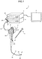
- FIG. 1 is a diagram illustrating a schematic configuration of an endoscope system 1 according to a first embodiment of the invention.
- the endoscope system 1 includes an endoscope 2, a control device 3, a light source device 4, a display device 5, and a treatment tool 6.
- the endoscope 2 captures an in-vivo image of a subject by inserting a distal end portion thereof into a body cavity of the subject.
- the control device 3 carries out predetermined image processing on the in-vivo image captured by the endoscope 2 and comprehensively controls overall operation of the endoscope system 1.
- the light source device 4 generates illumination light to be emitted from a distal end of the endoscope 2.
- the display device 5 displays the in-vivo image on which the control device 3 has carried out the image processing.
- the treatment tool 6 includes a function body such as a basket forceps or a snare at a distal end and is inserted into the endoscope 2 to be exposed from a distal end of a distal end portion 24.
- the endoscope 2 includes a flexible elongated insertion portion 21, an operating unit 22 connected on a proximal end side of the insertion portion 21 to receive input of various types of operation signals, and a universal cord 23 extending from the operating unit 22 in a direction different from a direction in which the insertion portion 21 extends and incorporating various types of cables for connection to the control device 3 and the light source device 4.
- the insertion portion 21 includes the distal end portion 24 having an image sensor, a bending portion 25 which is bendable and constituted by a plurality of curving pieces, and a long flexible tube portion 26 having flexibility and connected on a proximal end side of the bending portion 25.
- the image sensor receives light from the outside to photoelectrically convert the light to an electric signal and carries out predetermined signal processing on the electric signal.
- the image sensor is realized by using, for example, a CCD image sensor or a CMOS image sensor.
- a cable assembly in which a plurality of signal lines is bundled to transmit and receive the electric signals to and from the control device 3 is connected between the operating unit 22 and the distal end portion 24.
- the plurality of signal lines includes a signal line that transmits, to the control device 3, an image signal output by the image sensor, a signal line that transmits, to the image sensor, a control signal output by the control device 3, and the like.
- the operating unit 22 includes a curving knob 221 that curves the bending portion 25 in an up-down direction and a left-right direction, a treatment tool insertion portion 222 through which the treatment tool 6 such as a biopsy forceps, a laser scalpel, or an examination probe is inserted into the body cavity, and a plurality of switches 223 serving as operation input units to which operation instruction signals for peripheral devices such as air supply means, water supply means, and gas supply means, in addition to the control device 3 and the light source device 4, are input.
- a curving knob 221 that curves the bending portion 25 in an up-down direction and a left-right direction
- a treatment tool insertion portion 222 through which the treatment tool 6 such as a biopsy forceps, a laser scalpel, or an examination probe is inserted into the body cavity
- switches 223 serving as operation input units to which operation instruction signals for peripheral devices such as air supply means, water supply means, and gas supply means, in addition to the control device 3 and the light source device 4, are input.
- the universal cord 23 incorporates at least a light guide and the cable assembly.
- a connector portion 27 detachable from the light source device 4, and an electrical connector portion 28 detachable from the control device 3 and electrically connected to the connector portion 27 through a coil-shaped coil cable 270 are provided at an end portion of the universal cord 23 on a side different from a side on which the operating unit 22 is connected.
- control device 3 Based on a picture signal output from the distal end portion 24, the control device 3 generates an in-vivo image to be displayed by the display device 5.
- the control device 3 carries out white balance (WB) adjustment processing, gain adjustment processing, ⁇ correction processing, D/A conversion processing, format change processing, and the like.
- WB white balance
- the light source device 4 includes a light source, a rotary filter, a light source control unit, and the like.
- the light source is constituted by using a white light emitting diode (LED), a xenon lamp, or the like, and generates white light under the control of the light source control unit.
- the light generated by the light source is radiated from the distal end of the distal end portion 24 via the light guide.
- the display device 5 has a function for receiving, from the control device 3, the in-vivo image generated by the control device 3 through an image cable to display.
- the display device 5 is constituted by using, for example, a liquid crystal or organic electro luminescence (EL).
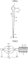
- FIG. 2 is a schematic diagram illustrating a schematic configuration of the treatment tool 6 included in the endoscope system 1 according to the first embodiment.
- the treatment tool 6 includes a grip member 61 (operation unit), a function unit 62, an operation wire 63, a housing 64, and a flexible tube portion 65.
- the grip member 61 includes a substantially cylindrical base portion 61a and a grip portion 61b provided at an end portion of the base portion 61a and having an opening passing through in a direction perpendicular to a longitudinal direction of the base portion 61a.
- the function unit 62 includes a basket forceps as the function body.
- the operation wire 63 is bendable and couples the grip member 61 to the function member 62.
- the housing 64 has a substantially tubular shape and is configured to house the base portion 61a and the operation wire 63 such that the base portion 61a and the operation wire 63 are movable forward and backward.
- the flexible tube portion 65 has a tube shape and is provided at an end portion of the housing 64 on a side different from where the base portion 61a is housed.
- the treatment tool 6 is disposed in the endoscope 2 such that the flexible tube portion 65 is inserted through the treatment tool insertion portion 222 and a distal end of the flexible tube portion 65 can be exposed from the distal end portion 24.
- the operation wire 63 and the flexible tube portion 65 have flexibility in accordance with the flexibility of the insertion portion 21.
- the operation wire 63 and the flexible tube portion 65 may have no flexibility depending on the intended use.
- the function unit 62 can be exposed to the outside from the distal end of the flexible tube portion 65 in accordance with forward and backward movement of the grip member 61 relative to the housing 64.
- the operation wire 63 is formed using a wire material made of stainless steel such as SUS.
- the housing 64 forms a hollow space having a stepped shape. One end of the hollow space in the housing 64 has a diameter into which the base portion 61a can be inserted and the other end thereof has a diameter into which the operation wire 63 can be inserted.
- FIG. 3 is a partial cross-sectional view illustrating a configuration of main parts of the treatment tool according to the first embodiment.
- the function unit 62 includes a basket portion 621, a first fixing portion 622 (fixing portion), and a second fixing portion 623 (second fixing portion).
- the basket portion 621 forms a basket shape using a plurality of elastic wires 6211 to 6214.
- the first fixing portion 622 is provided on a proximal end side of the basket portion 621, collectively houses each end portion of the plurality of elastic wires 6211 to 6214 so as to be fixed, and is connected to the operation wire 63.
- the second fixing portion 623 is provided on a distal end side of the basket portion 621, and collectively houses each end portion of the plurality of elastic wires 6211 to 6214 so as to be fixed.
- the first embodiment will be described assuming that the basket shape is formed by the four elastic wires 6211 to 6214.
- the basket shape may be formed by, for example, three or five or more elastic wires.
- Each of the plurality of elastic wires 6211 to 6214 is formed using a wire material made of a super-elastic material (super-elastic alloy).
- the super-elastic alloy is alloy that has a shape-memory property (shape-recovery property) at a temperature equal to or higher than a transformation point and has a transformation point equal to or lower than a normal temperature.
- shape-memory property shape-recovery property
- nickel-titanium alloy or ferro-manganese-silicon alloy can be used.
- the elastic wires 6211 to 6214 each have a substantially arc-shaped (C-shaped) bending shape at a central portion.
- the basket portion 621 has a basket shape in which both end portions of each of the plurality of elastic wires 6211 to 6214 having the above-mentioned shape are separately fixed to the first fixing portion 622 and the second fixing portion 623 such that the C shapes of two opposing elastic wires face each other, and a plane passing through a pair of opposing elastic wires intersect a plane passing through another pair of opposing elastic wires. It is preferable that the planes passing through the elastic wires perpendicularly intersect.
- the first fixing portion 622 and the second fixing portion 623 are formed using stainless steel such as SUS and fix both ends of the basket portion 621 individually such that the plurality of elastic wires 6211 to 6214 satisfies the positional relationships described above.
- the first fixing portion 622 has a cylindrical shape that can be inserted into a hollow portion 651 of the flexible tube portion 65.
- the second fixing portion 623 has a substantially cylindrical shape, where a diameter of an end portion thereof on a side different from a side on which the elastic wires 6211 to 6214 are connected (distal end portion) is made smaller toward the distal end.
- the hollow portion 651 has a diameter into which the first fixing portion 622 can be inserted.
- FIG. 4 is a cross-sectional view illustrating the configuration of the principal portion of the treatment tool according to the first embodiment.
- FIG. 5 is a cross-sectional view illustrating a cross-section of the treatment tool taken along line A-A in FIG. 4 .
- the first fixing portion 622 includes a first hole 6221 forming a cylindrical hollow space extending from an end portion on a side on which the operation wire 63 is coupled (distal end portion) toward the other end portion, and four second holes 6222 to 6225 extending from an end portion on a side different from the distal end portion (other end portion) toward the distal end portion and communicating with the first hole 6221.
- Sphere-shaped portions 6211a to 6214a serving as engagement portions each of which has a sphere shape having a diameter equal to or larger than a diameter of the wire material of each of the elastic wires 6211 to 6214, are provided at the end portions of the elastic wires 6211 to 6214, respectively. It is further preferable that the diameter of the sphere-shaped portion be equal to or larger than, for example, a diameter of an opening of the second hole 6222.
- a proximal end portion of the elastic wire 6211 including the sphere-shaped portion 6211a is housed in the first hole 6221 and also inserted into the second hole 6222. The same applies to the elastic wires 6212 to 6214.
- the first hole 6221 houses the end portion of the elastic wire 6211 including the sphere-shaped portion 6211a and also is filled with a sealing member 66.
- the second holes 6222 to 6225 are also filled with the sealing member 66. Resin such as an adhesive or solder is used as the sealing member 66.
- the elastic wire and the operation wire 63 are fixed in the inside of the first hole 6221 through this sealing member 66.
- the sphere-shaped portion 6211a is fixed through the sealing member 66, whereby the elastic wire 6211 is prevented from coming off and being removed from the first hole 6221 and the second hole 6222.
- the elastic wires 6211 to 6214 can be prevented from moving in the inside of the first fixing portion 622.
- FIG. 6 is a cross-sectional view illustrating the configuration of the principal portion of the treatment tool according to the first embodiment.
- FIG. 7 is a cross-sectional view illustrating a cross-section of the treatment tool taken along line B-B in FIG. 6 .
- the second fixing portion 623 also includes a first hole 6231 forming a cylindrical hollow space extending from a distal end portion toward the other end portion, and four second holes 6232 to 6235 extending from an end portion on a side different from the distal end portion (other end portion) toward the distal end portion and communicating with the first hole 6231.
- the first hole 6231 and the four second holes 6232 to 6235 form a through-hole (insertion hole) passing through both ends of the second fixing portion 623.
- Sphere-shaped portions 6211b to 6214b (engagement portions), each of which has a sphere shape having a diameter equal to or larger than a diameter of the wire material of each of the elastic wires 6211 to 6214, are provided at the end portions of the elastic wires 6211 to 6214, respectively. It is preferable that the diameters of the sphere-shaped portions 6211b to 6214b be equal to or larger than diameters of openings of the second holes 6232 to 6235, respectively, since the sphere-shaped portions 6211b to 6214b are engaged with the second holes 6232 to 6235, respectively.
- the distal end portions of the elastic wires 6211 to 6214 including the sphere-shaped portions 6211b to 6214b, respectively, are housed in the first hole 6231 and also inserted into the second holes 6232 to 6235, respectively.
- the first hole 6231 and the second holes 6232 to 6235 are filled with a sealing member 67.
- the sealing member 67 include resin such as an adhesive. Solder can be also used as long as processing can be carried out at a temperature that does not affect the shape-memory property of the elastic wire.
- the elastic wires 6211 to 6214 are fixed in the inside of the first hole 6231 through the sealing member 67.
- Each of the sphere-shaped portions 6211b to 6214b is fixed through the sealing member 67, whereby the elastic wires 6211 to 6214 are prevented from coming off and being removed from the first hole 6231 and the second holes 6232 to 6235, respectively.
- the elastic wires 6211 to 6214 can be prevented from moving in the inside of the second fixing portion 643.
- the function unit 62 is inserted into the hollow portion 651 of the flexible tube portion 65 or removed from the hollow portion 651.
- each of the elastic wires 6211 to 6214 is compressed in accordance with the diameter of the hollow portion 651 and made into a substantially straight line shape to be housed within the hollow portion 651.
- the elastic wires 6211 to 6214 each of which has the shape-memory property, individually form the C shapes at the central portions thereof to form the basket shape described earlier.
- the basket portion 621 first houses in-vivo tissue of the subject into the inside of the basket shape while being released to the outside of the hollow portion 651.
- the grip member 61 grip portion 61b
- the basket portion 621 is partially housed in the hollow portion 651 to reduce an inner space formed by the basket shape, whereby the in-vivo tissue is captured and collected.
- FIGS. 8 to 11 are diagrams illustrating a method for manufacturing the treatment tool according to the first embodiment of the invention and illustrating a method for connecting the elastic wires and the first fixing portion 622 in the function unit 62.
- the proximal end portions of the elastic wires 6211 to 6214 are inserted into the first hole 6221 and the second holes 6222 to 6225, respectively, of the first fixing portion 622 ( FIG. 8 , insertion step). At this time, the proximal end portions of the elastic wires 6211 to 6214 are exposed to the outside from the first hole 6221.
- the sphere-shaped portions 6211a to 6214a are formed at the proximal end portions of the elastic wires 6211 to 6214, respectively ( FIG. 9 : formation step).
- the sphere-shaped portion 6211a is formed by melting the elastic wire 6211 using arc discharge.
- the sphere-shaped portions 6212a to 6214a are also formed in the elastic wires 6212 to 6214, respectively, through the similar processing.
- the elastic wire may be melted using plasma discharge.
- the sphere-shaped portions 6211b to 6214b are formed at other ends of the elastic wires 6211 to 6214, respectively.
- the end portions of the elastic wires 6211 to 6214 are housed in the first hole 6221 ( FIG. 11 ).
- the sphere-shaped portions 6211a to 6214a of the elastic wires 6211 to 6214 are disposed within the first hole 6421.
- the operation wire 63 is partially inserted into the first hole 6221 from an opposite side of the second holes 6222 to 6225.
- the first hole 6221 and the second holes 6222 to 6225 are filled with the sealing member 66 to be fixed (fixing step), whereby, as illustrated in FIG. 4 , a structure in which the elastic wires 6211 to 6214 are fixed to the first fixing portion 622 through the sealing member 66 is obtained.
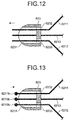
- FIGS. 12 and 13 are diagrams illustrating the method for manufacturing the treatment tool according to the first embodiment of the invention and illustrating a method for connecting the elastic wires and the second fixing portion 623 in the function unit 62.
- the distal end portions of the elastic wires 6211 to 6214 are inserted into the first hole 6231 and the second holes 6232 to 6235, respectively (refer to FIG. 7 ), of the second fixing portion 623 ( FIG. 12 , second insertion step). At this time, the distal end portions of the elastic wires 6211 to 6214 are exposed to the outside from the first hole 6231.
- the sphere-shaped portions 6211b to 6214b are formed at the distal end portions of the elastic wires 6211 to 6214, respectively ( FIG. 13 , second formation step).
- the sphere-shaped portion is formed in a manner similar to the above-mentioned formation step (refer to FIGS. 10(a) and 10(b) ).
- the end portions of the elastic wires 6211 to 6214 are housed in the first hole 6231 ( FIG. 13 ).
- the sphere-shaped portions 6211b to 6214b of the elastic wires 6211 to 6214 are disposed within the first hole 6231.
- the first hole 6231 and the second holes 6232 to 6235 are filled with the sealing member 67 to be fixed (second fixing step), whereby, as illustrated in FIG. 6 , a structure in which the elastic wires 6211 to 6214 are fixed to the second fixing portion 623 through the sealing member 67 is obtained.
- the sphere-shaped portions 6211a to 6214a (6211b to 6214b) are provided in the plurality of elastic wires 6211 to 6214, respectively, each of which has the super-elastic properties, so as to be fixed to the first fixing portion 622 (second fixing portion 623) through the sealing member 66 (67). Therefore, the wires can be fixed while the super-elastic properties of the wires are maintained.
- an adhesive (or solder) is used as the sealing members 66 and 67. Accordingly, in the process of manufacturing, the elastic wires 6211 to 6214 are prevented from losing the super-elastic properties due to heat, while the elastic wires 6211 to 6214 can be surely fixed to the first fixing portion 622 and the second fixing portion 623.
- the sphere-shaped portions 6211a to 6214a are provided in the plurality of elastic wires 6211 to 6214, respectively, such that the sphere-shaped portions 6211a to 6214a prevent the elastic wires from coming off from the second holes 6222 to 6225, respectively. As a result, certainty of prevention of the coming-off in the respective elastic wires 6211 to 6214 can be enhanced.
- the first embodiment has been described assuming that the elastic wires 6211 to 6214 are fixed to the second fixing portion 623 using the sealing member 67.
- maximum diameters of the sphere-shaped portions 6211b to 6214b are larger than opening diameters of the second holes 6232 to 6235, respectively, a configuration without the sealing member 67 can be applied.
- the first embodiment has also been described assuming that the first hole 6221 and the second holes 6222 to 6225 are filled with the sealing member 66.
- the sealing member 66 may be provided partially in the first hole 6221 as long as the sphere-shaped portions 6211a to 6214a can be fixed (the sphere-shaped portions can be engaged with the second holes) in the first hole 6221.
- FIG. 14 is a diagram illustrating a configuration of main parts of a treatment tool according to a variation 1-1 of the first embodiment.
- the above-mentioned first embodiment has been described assuming that the sphere-shaped portion is formed by melting the elastic wire using the arc discharge (or plasma discharge).
- a shape of an end portion may be changed by using press jigs 71a and 71b as illustrated in FIG. 14(a) to press an elastic wire 6215.
- the quadrangular prism-shaped press jigs 71a and 71b are arranged such that center axes thereof in the longitudinal direction match.
- the end portion of the elastic wire 6215 is then placed on these center axes to be pressed.
- a flat plate portion 6215a (engagement portion) larger than the diameter of the wire material of the elastic wire 6215 is formed at the end portion of the elastic wire 6215, which has been pressed by the press jigs 71a and 71b.
- the flat plate portion 6215a has a function for preventing the coming-off from the first and second fixing portions, as in the above-mentioned sphere-shaped portion.
- FIG. 15 is a diagram illustrating a configuration of main parts of a treatment tool according to a variation 1-2 of the first embodiment.
- the above-mentioned first embodiment has been described assuming that the sphere-shaped portion is formed by melting the elastic wire using the arc discharge (or plasma discharge).
- a shape of an end portion may be changed by using press jigs 71c and 71d as illustrated in FIG. 15(a) to press an elastic wire 6216.
- the quadrangular prism-shaped press jigs 71c and 71d are arranged at positions in which the press jigs 71c and 71d do not make contact with each other during vertical movement thereof by making center axes thereof in the longitudinal direction eccentric.
- the end portion of the elastic wire 6216 is placed between the center axes of the press jigs 71c and 71d to be pressed by the press jigs 71c and 71d.
- a bending portion 6216a (engagement portion) whose end portion has a shape bending substantially at right angle by being pressed by the press jigs 71c and 71d is formed at the end portion of the elastic wire 6216.
- the bending portion 6216a has a function for preventing the coming-off from the first and second fixing portions, as in the above-mentioned sphere-shaped portion.
- FIG. 16 is a cross-sectional view illustrating a configuration of main parts of a treatment tool according to a second embodiment of the invention.
- FIG. 17 is a cross-sectional view illustrating a cross-section of the treatment tool taken along line C-C in FIG. 16 .
- Elements which are the same as those of FIG. 4 or the like are denoted by the same reference signs.
- the above-mentioned first embodiment has been described assuming that the sphere-shaped portion is provided in each of the plurality of elastic wires to prevent the coming-off from the second fixing portion 623.
- the second embodiment achieves an effect for preventing the coming-off from a second fixing portion by forming a bundling portion in which distal end portions of elastic wires are bundled together.
- a second fixing portion 624 according to the second embodiment is formed of stainless steel such as SUS and houses a distal end portion of a basket portion 621 so as to be fixed.
- the second fixing portion 624 has a substantially cylindrical shape, where a diameter of an end portion thereof on a side different from a side on which the elastic wires 6211 to 6214 are connected (distal end portion) is made smaller toward the distal end.
- the second fixing portion 624 includes a first hole 6241 forming a cylindrical hollow space extending from a distal end portion toward the other end portion, and a second hole 6242 extending from an end portion on a side different from the distal end portion (other end portion) toward the distal end portion, communicating with the first hole 6241, and having a diameter smaller than a diameter of an opening of the first hole 6241.
- a center axis of the opening of the first hole 6241 matches a center axis of an opening of the second hole 6242, and a through-hole (insertion hole) whose cross-section has a stepped shape is formed.
- a bundling portion 6217 (engagement portion) in which the respective elastic wires 6211 to 6214 are bundled together is provided.
- a maximum diameter of the bundling portion 6217 is larger than the diameter of the opening of the second hole 6242.
- the bundling portion 6217 has a function for preventing the second fixing portion 624 from coming off the second hole 6242, as in the above-mentioned sphere-shaped portion.
- the elastic wires 6211 to 6214 which has been subjected to processing similar to the above-mentioned method ( FIGS. 12 and 13 ) to form the bundling portion 6217, are then fixed to the second fixing portion 624.
- the first hole 6241 and the second hole 6242 are filled with a sealing member 67a. Resin such as an adhesive or solder is used as the sealing member 67a.
- the elastic wires 6211 to 6214 can be prevented from moving in the inside of the second fixing portion 624.
- the bundling portion 6217 is provided in the plurality of elastic wires 6211 to 6214 having the super-elastic properties so as to be fixed to the second fixing portion 624 through the sealing member 67a. Therefore, the wires can be fixed while the super-elastic properties of the wires are maintained.
- the bundling portion 6217 in which the plurality of elastic wires 6211 to 6214 is bundled together is provided, whereby processing steps for the elastic wires 6211 to 6214 can be reduced compared to the above-mentioned first embodiment.
- the second embodiment has been described assuming that the elastic wires 6211 to 6214 are fixed to the second fixing portion 624 using the sealing member 67a.
- a configuration without the sealing member 67a can be applied.
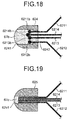
- FIG. 18 is a cross-sectional view illustrating a configuration of main parts of a treatment tool according to a variation 2-1 of the second embodiment.
- the above-mentioned elastic wires 6211 to 6214 having the sphere-shaped portions 6211b to 6214b, respectively, according to the first embodiment may be connected to the second fixing portion 624 described above.
- the sphere-shaped portions 6211b to 6214b are closely provided on the same plane and, when, for example, relative to one plane, the sphere-shaped portions 6211b to 6214b are arranged such that respective centers thereof are placed on this plane and circles including cross-sections of the sphere-shaped portions 6211b to 6214b are minimized in area on this plane, the sphere-shaped portions 6211b to 6214b are formed so as to be larger in area than the opening of the second hole 6242.
- the respective sphere-shaped portions 6211b to 6214b are fixed through a sealing member 67b.
- a sealing member 67b In a case where, as illustrated in FIG. 18 , the sphere-shaped portions 6211b to 6214b are not placed on the same plane, it is preferable that positions where the sphere-shaped portions are formed be adjusted at the distal ends of the elastic wires.
- first and second embodiments have been described assuming that the elastic wires 6211 to 6214 are fixed to the first and second fixing portions using the sealing members 66, 67, 67a, and 67b.
- sealing member instead of the sealing member, swaging in which a diameter of a through-hole is reduced by being applied with a load from the outside may be employed to pinch and fix elastic wires.
- FIG. 19 is a cross-sectional view illustrating a configuration of main parts of a treatment tool according to a third embodiment of the invention. Elements which are the same as those of FIG. 3 or the like are denoted by the same reference signs.
- the above-mentioned first embodiment has been described assuming that the sphere-shaped portions 6211b to 6214b are provided in the elastic wires 6211 to 6214, respectively, to prevent the coming-off from the second fixing portion 623.
- the third embodiment achieves an effect for preventing a plurality of elastic wires from coming off a second fixing portion through solder or an adhesive.
- a second fixing portion 625 according to the third embodiment is formed of stainless steel such as SUS and houses one end of a basket portion 621 so as to be fixed.
- the second fixing portion 625 has a substantially cylindrical shape, where a diameter of an end portion thereof on a side different from a side on which the elastic wires 6211 to 6214 are connected (distal end portion) is made smaller toward the distal end.
- a hole portion 6251 insertion hole forming a cylindrical hollow space extending from the distal end portion toward the other end portion is formed in the second fixing portion 625.
- the elastic wires 6211 to 6214 are housed in the hole portion 6251 and then fixed to the second fixing portion 625. At this time, the hole portion 6251 is filled with a sealing member 67c. Resin such as an adhesive or solder is used as the sealing member 67c. As a result, the elastic wires 6211 to 6214 can be prevented from moving in the inside of the second fixing portion 625 or coming off the second fixing portion 625.
- one end of each of the plurality of elastic wires 6211 to 6214 having the super-elastic properties is housed in the second fixing portion 625 such that the elastic wires are fixed to the second fixing portion 625 by being filled with the sealing member 67c. Therefore, the wires can be fixed while the super-elastic properties of the wires are maintained.
- FIGS. 20 and 21 are diagrams illustrating a configuration of main parts of a treatment tool according to a fourth embodiment of the invention. Elements which are the same as those of FIG. 3 or the like are denoted by the same reference signs.
- the above-mentioned first embodiment has been described assuming that the sphere-shaped portion 6211a or the like is provided in each of the elastic wires 6211 to 6214 to prevent the coming-off from the first fixing portion 622.
- the fourth embodiment achieves an effect for preventing the coming-off by forming an engagement portion at each proximal end portion of a plurality of elastic wires to fix by swaging a first fixing portion.
- a substantially cylindrical first fixing portion 626 according to the fourth embodiment is formed of stainless steel such as SUS and houses the other end of a basket portion 621 and an operation wire 63a so as to be fixed.
- a hole portion 6261 (insertion hole) forming a cylindrical hollow space extending from a distal end portion toward the other end portion is formed in the first fixing portion 626.
- a flat plate-shaped flat plate portion 6211c formed by changing a shape thereof through pressure so as to have a maximum diameter equal to or larger than the diameter of the wire material of the elastic wire 6211 is provided at an end portion (other end) of the elastic wire 6211 (refer to FIG. 21 ).
- the flat plate portions are also formed in the elastic wires 6212 to 6214 ( FIG. 20 illustrates flat plate portions 6212c and 6213c formed in the elastic wires 6212 and 6213, respectively).
- FIG. 22 is a cross-sectional view illustrating a method for manufacturing the treatment tool according to the fourth embodiment.
- the elastic wires 6211 to 6214 are housed in the hole portion 6261 of the first fixing portion 626 and then fixed by swaging the first fixing portion 626.
- a load is applied to the first fixing portion 626 from a direction substantially perpendicular to a center axis of the cylindrical shape (center axis of the hole portion 6261) to reduce a diameter of an outer circumference thereof in size.
- a diameter of the hole portion 6261 is also reduced in size.
- the flat plate portions (6211c to 6213c) of the elastic wires 6211 to 6214 and an end portion of the operation wire 63a are squeezed by the hole portion 6261.
- the elastic wires 6211 to 6214 can be prevented from moving in the inside of the first fixing portion 626 or coming off the first fixing portion 626.
- a diameter of the operation wire 63a be equal to or larger than a diameter of an outer circumference of a pile obtained by collecting all of the flat plate portions of the elastic wires 6211 to 6214 together.
- the other end of each of the plurality of elastic wires 6211 to 6214 having the super-elastic properties is housed in the first fixing portion 626, and then the first fixing portion 626 is swaged so that the other end of each of the elastic wires 6211 to 6214 is fixed. Therefore, the wires can be fixed while the super-elastic properties of the wires are maintained.
- a mode for fixing both of the ends of the elastic wires 6211 to 6214 is not limited to a combination according to each of the first to fourth embodiments.
- the treatment tool can be configured such that both of the ends are fixed by combining the respective fixing modes according to the first to fourth embodiments independently.
- the respective fixing modes for the first and second fixing portions described above can be selected as necessary for the first and second fixing portions.
- the fixing mode for the first fixing portion can be replaced with the fixing mode for the second fixing portion.
- the respective fixing modes can be applied to any configuration as long as the engagement portions are formed at least at one ends of the elastic wires 6211 to 6214 and both ends of the elastic wires 6211 to 6214 are fixed by the first and second fixing portions.
- FIGS. 23 and 24 are diagrams illustrating a configuration of main parts of a treatment tool according to a fifth embodiment of the invention. Elements which are the same as those of FIG. 3 or the like are denoted by the same reference signs.
- the above-mentioned first embodiment has been described assuming that the function unit 62 includes the basket forceps as the function body.
- a function unit includes a snare as the function body.
- the function unit 62a includes an annular-shaped portion 627 and a fixing portion 622a.
- the annular-shaped portion 627 has a substantially annular shape and makes both end portions of a single elastic wire 6271 come close to each other such that a central portion of the elastic wire 6271 has a predetermined radius of curvature.
- the fixing portion 622a collectively houses both of the end portions of the elastic wire 6271 so as to be fixed and is connected to an operation wire 63.
- the elastic wire 6271 is formed using a wire material made of a super-elastic material (super-elastic alloy).
- the super-elastic alloy is alloy that has a shape-memory property (shape-recovery property) at a temperature equal to or higher than a transformation point and has a transformation point equal to or lower than a normal temperature.
- shape-memory property shape-recovery property
- nickel-titanium alloy or ferro-manganese-silicon alloy can be used.
- the fixing portion 622a is formed using stainless steel such as SUS and fixes both ends (a distal end portion and a proximal end portion) of the annular-shaped portion 627 thereto.
- the fixing portion 622a also has a cylindrical shape that can be inserted into a hollow portion 651 of a flexible tube portion 65.
- the fixing portion 622a includes a first hole 6221 forming a cylindrical hollow space extending from an end portion on a side on which the operation wire 63 is coupled (distal end portion) toward the other end portion, and two second holes 6226 and 6227 communicating with the first hole 6221 and each forming an opening at an end portion on a side different from the distal end portion (proximal end portion).
- sphere-shaped portions 6271a and 6271b engagement portions, each of which has a sphere shape having a diameter equal to or larger than a diameter of the wire material, are provided. It is further preferable that the diameter of the sphere-shaped portion be equal to or larger than, for example, a diameter of the opening of each of the second holes 6226 and 6227.
- the proximal end portion of the elastic wire 6271 including the sphere-shaped portion 6271a is housed in the first hole 6221 and also inserted into the second hole 6226.
- the distal end portion of the elastic wire 6271 including the sphere-shaped portion 6271b is housed in the first hole 6221 and also inserted into the second hole 6227.
- Both of the end portions of the elastic wire 6271 (sphere-shaped portions 6271a and 6271b) housed in the first hole 6221 are fixed to the fixing portion 622a through a sealing member 66a.
- a conductive adhesive such as solder is used as the sealing member 66a.
- the sphere-shaped portion 6271a is fixed through the sealing member 66a, whereby the elastic wire 6271 is prevented from coming off and being removed from the first hole 6221 and the second hole 6226.
- the elastic wire 6271 can be prevented from moving in the inside of the fixing portion 622a.
- the function unit 62a is inserted into the hollow portion 651 of the flexible tube portion 65 or removed from the hollow portion 651.
- the elastic wire 6271 is compressed in accordance with the diameter of the hollow portion 651 and made into a substantially straight line shape to be housed within the hollow portion 651.
- the annular-shaped portion 627 first houses in-vivo tissue of the subject into the inside of the annular shape while being released to the outside of the hollow portion 651.
- the grip member 61 is moved in a direction for being removed from the housing 64, the annular-shaped portion 627 is partially housed in the hollow portion 651 to reduce an inner space formed by the annular-shaped portion 627, whereby the in-vivo tissue is captured.
- a high-frequency electric current is applied to the elastic wire 6271 through the operation wire 63 and a cable (not illustrated) and then heat is generated through the electrification.
- the captured in-vivo tissue can be cut out using the heat.
- the proximal end portion of the elastic wire 6271 is inserted into the second hole 6226 in the fixing portion 622a while the distal end portion thereof is inserted into the second hole 6227. Thereafter, the sphere-shaped portions 6271a and 6271b are each formed therein and then the elastic wire 6271 is fixed through the sealing member 66a.
- the sphere-shaped portions 6271a and 6271b are provided at both of the end portions of the elastic wire 6271 having the super-elastic properties so as to be fixed to the fixing portion 622a through the sealing member 66a. Therefore, both of the end portions of the wire can be fixed while the super-elastic properties of the wire are maintained.
- FIGS. 25 and 26 are diagrams illustrating a configuration of main parts of a treatment tool according to a sixth embodiment of the invention. Elements which are the same as those of FIG. 3 or the like are denoted by the same reference signs.
- the above-mentioned first embodiment has been described assuming that the function unit 62 includes the basket forceps as the function body.
- a function unit includes a tripod grasping forceps as the function body.
- the function unit 62b includes a tripod portion 628 and a fixing portion 622b.
- the tripod portion 628 is formed by three elastic wires 6281 to 6283 having predetermined shapes to have a shape in which a space surrounded by the elastic wires 6281 to 6283 is radially expanded from a proximal end portion side toward a distal end portion side.
- the fixing portion 622b collectively houses the proximal end portions of the elastic wires 6281 to 6283 of the tripod portion 628 so as to be fixed and is connected to an operation wire 63.
- the elastic wires 6281 to 6283 are formed using a wire material made of a super-elastic material (super-elastic alloy).
- the super-elastic alloy is alloy that has a shape-memory property (shape-recovery property) at a temperature equal to or higher than a transformation point and has a transformation point equal to or lower than a normal temperature.
- shape-memory property shape-recovery property
- nickel-titanium alloy or ferro-manganese-silicon alloy can be used.
- the fixing portion 622b is formed using stainless steel such as SUS and fixes the proximal end portion of the tripod portion 628 thereto.
- the fixing portion 622b also has a cylindrical shape that can be inserted into a hollow portion 651 of a flexible tube portion 65.
- the fixing portion 622b includes a first hole 6221 forming a cylindrical hollow space extending from an end portion on a side on which the operation wire 63 is coupled (distal end portion) toward the other end portion, and three second holes ( FIG. 26 only illustrates the second holes 6228 and 6229) communicating with the first hole 6221 and forming an opening at an end portion on a side different from the distal end portion (proximal end portion).
- sphere-shaped portions (Only the sphere-shaped portions 6281a and 6282a are illustrated in FIG. 26 ) serving as engagement portions, each of which has a sphere shape having a diameter equal to or larger than a diameter of the wire material, are provided. It is further preferable that the diameter of the sphere-shaped portion be equal to or larger than, for example, a diameter of the opening of the second hole.
- the proximal end portions of the elastic wires 6281 to 6283 including the sphere-shaped portions are housed in the first hole 6221 and also inserted into the second holes individually.
- the proximal end portions of the elastic wires 6281 to 6283 housed in the first hole 6221 are fixed to the fixing portion 622b through a sealing member 66b. Resin such as an adhesive or solder is used as the sealing member 66b.
- the sphere-shaped portion 6281a is fixed through the sealing member 66b, whereby the elastic wire 6281 is prevented from coming off and being removed from the first hole 6221 and the second hole 6228.
- the elastic wire 6281 can be prevented from moving in the inside of the fixing portion 622b.
- the function unit 62b is inserted into the hollow portion 651 of the flexible tube portion 65 or removed from the hollow portion 651.
- the elastic wires 6281 to 6283 are compressed in accordance with the diameter of the hollow portion 651 and made into a substantially straight line shape to be housed within the hollow portion 651.
- shapes of the respective elastic wires 6281 to 6283 having the shape-memory property are changed so as to have the predetermined shapes.
- the tripod portion 628 first encloses in-vivo tissue of the subject on the distal end portion side of the elastic wires 6281 to 6283 while being released to the outside of the hollow portion 651.
- the tripod portion 628 is partially housed in the hollow portion 651 to reduce the space surrounded by the elastic wires 6281 to 6283, whereby the in-vivo tissue is captured and collected.
- the sphere-shaped portions are provided at the proximal end portions of the respective elastic wires 6281 to 6283 having the super-elastic properties so as to be fixed to the fixing portion 622b through the sealing member 66b. Therefore, the wires can be fixed while the super-elastic properties of the wires are maintained.
- first to sixth embodiments are merely examples for carrying out the invention and are not construed to limit the invention.
- the invention can be applied to any treatment tool formed using a wire material made of a super-elastic material and used by fixing at least a proximal end of an elastic wire having a predetermined shape.
- the various inventions can be made by combining multiple elements disclosed in the respective embodiments or variations as necessary. It is clear from the description above that the invention can be variously modified depending on specifications or the like, and furthermore, other different embodiments can be made within the scope of the invention.
Landscapes
- Health & Medical Sciences (AREA)
- Life Sciences & Earth Sciences (AREA)
- Surgery (AREA)
- General Health & Medical Sciences (AREA)
- Public Health (AREA)
- Veterinary Medicine (AREA)
- Nuclear Medicine, Radiotherapy & Molecular Imaging (AREA)
- Animal Behavior & Ethology (AREA)
- Molecular Biology (AREA)
- Engineering & Computer Science (AREA)
- Biomedical Technology (AREA)
- Heart & Thoracic Surgery (AREA)
- Medical Informatics (AREA)
- Orthopedic Medicine & Surgery (AREA)
- Vascular Medicine (AREA)
- Biophysics (AREA)
- Radiology & Medical Imaging (AREA)
- Physics & Mathematics (AREA)
- Pathology (AREA)
- Optics & Photonics (AREA)
- Surgical Instruments (AREA)
- Endoscopes (AREA)
Abstract
Description
- The present invention relates to a method for manufacturing a treatment tool used for an endoscope, and to the treatment tool.
- An endoscope system has been used in a medical field in the past to observe an organ of a subject such as a patient. As the endoscope system described above, an endoscope system has been known such as one that includes a flexible elongated insertion portion configured to be inserted into a body cavity of the subject, an image sensor provided at a distal end of the insertion portion to capture an in-vivo image, and an external device connected to the insertion portion through a cable to process the in-vivo image captured by the image sensor and display the in-vivo image on a display unit or the like. A medical doctor or the like inserts a treatment tool into the insertion portion to operate while looking at the in-vivo image captured by the image sensor, whereby a predetermined medical treatment for a subject can be performed in the inside of the subject.
- Examples of the treatment tool used for the endoscope system include a wire-loop type treatment tool. The wire-loop type treatment tool has a structure in which a function body made of a wire is inserted into a tubular member in a removable manner. Specific examples of the function body include a snare whose distal end portion has a curving shape in an annular form. This wire is housed in the tubular member to reduce a diameter of a ring in size and tissue is captured to be thermally cut out by applying a high-frequency electric current to the wire.
- A basket forceps is also exemplified as the function body. The basket forceps has a basket shape in which multiple wires whose central portions have curving shapes are fixed at end portions thereof while opposing wires are curved in opposite directions, and these wires are housed in the tubular member to reduce an inner space formed by the basket during the capturing. In this function body, each end portion of the plurality of wires is fixed by being brazed (for example, refer to Patent Literature 1).
- Here, in recent years, in order to enhance the shape reproducibility during insertion and removal into and from the tubular member, super-elastic alloy such as nickel-titanium alloy has been employed for the wires used in the above-mentioned function bodies.
- Patent Literature 1:
JP 3629111 B2 - However, the super-elastic alloy such as nickel-titanium alloy has had a problem in that the wettability thereof makes it difficult to fix the wires through brazing or, even when the wires are fixed, heating in brazing may alter super-elastic properties such as a shape-memory property. For this reason, there is a need to fix the wires while maintaining the super-elastic properties of the wires made of super-elastic alloy.
- The present invention has been made in view of the foregoing, and an object of the invention is to provide a method for manufacturing a treatment tool and to provide the treatment tool capable of fixing wires while maintaining the super-elastic properties of the wires.
- In order to solve the above described problems and achieve the object, a method for manufacturing a treatment is provided. The treatment tool includes: a function body having at least one elastic wire formed of a wire material made of a super-elastic material and having a predetermined shape, and a fixing portion having an insertion hole into which the elastic wire is insertable to house at least a proximal end portion of the elastic wire in the insertion hole so as to be fixed to the fixing portion; a tube portion configured to house the function body; and an operation unit configured to insert and remove the function body into and from the tube portion. The method according to the invention includes: an insertion step of inserting the proximal end portion of the elastic wire into the insertion hole of the fixing portion; a formation step of forming, at the proximal end portion of the elastic wire, an engagement portion for engaging with the insertion hole of the fixing portion; and a fixing step of fixing the proximal end portion of the elastic wire to the fixing portion.
- In the method for manufacturing the treatment tool according to the above-described invention, the formation step includes forming the engagement portion by melting a distal end of the elastic wire using arc discharge.
- In the method for manufacturing the treatment tool according to above-described invention, the formation step includes forming the engagement portion by pressing the elastic wire to change a shape of the elastic wire.
- In the method for manufacturing the treatment tool according to above-described invention, the formation step includes forming the engagement portion by bending a distal end of the elastic wire.
- In the method for manufacturing the treatment tool according to above-described invention, the fixing step includes sealing at least part of the insertion hole.
- In the method for manufacturing the treatment tool according to above-described invention, the fixing step includes reducing a diameter of the insertion hole by applying a load thereto from outside.
- In the method for manufacturing the treatment tool according to above-described invention, the fixing step includes fixing, to the fixing portion, the proximal end portion of the elastic wire, and an operation wire that is connected to the operation unit to operate a movement of the function body.
- In the method for manufacturing the treatment tool according to above-described invention, the function body further includes a second fixing portion having an insertion hole into which each of a plurality of elastic wires is inserted to house other end portion of each of the plurality of elastic wires in the insertion hole so as to be fixed to the second fixing portion. The method further includes: a second insertion step of inserting the other end portion of each of the plurality of elastic wires into the insertion hole of the second fixing portion; a second formation step of forming, at the other end portion of each of the plurality of elastic wires, an engagement portion for engaging with the insertion hole of the second fixing portion; and a second fixing step of fixing the other end portion of each of the plurality of elastic wires to the second fixing portion.
- In the method for manufacturing the treatment tool according to above-described invention, the second fixing step includes sealing at least part of the insertion hole.
- In the method for manufacturing the treatment tool according to above-described invention, the second fixing step includes reducing a diameter of the insertion hole by applying a load thereto from outside.
- In the method for manufacturing the treatment tool according to above-described invention, the insertion step further includes inserting a distal end portion of the elastic wire into the insertion hole of the fixing portion, the formation step further includes forming, at the distal end portion of the elastic wire, a second engagement portion for engaging with the insertion hole, and the fixing step includes fixing the distal end portion and the proximal end portion of the elastic wire to the fixing portion.
- A treatment tool according to the invention includes: a function body having at least one elastic wire formed of a wire material made of a super-elastic material and having a predetermined shape, and a fixing portion having an insertion hole into which the plurality of elastic wires is insertable to house at least a proximal end portion of each of the elastic wires in the insertion hole so as to be fixed to the fixing portion; a tube portion configured to house the function body; and an operation unit configured to insert and remove the function body into and from the tube portion.
- According to the present invention, an engagement portion is provided at least at one end of each of a plurality of elastic wires having super-elastic properties, and both ends of each of the plurality of elastic wires are housed in a first fixing portion or a second fixing portion so as to be fixed thereto. Therefore, it possible to fix the wires while maintaining the super-elastic properties of the wires.
-
-
FIG. 1 is a diagram illustrating a schematic configuration of an endoscope system according to a first embodiment of the invention. -
FIG. 2 is a schematic view illustrating a schematic configuration of a treatment tool included in the endoscope system according to the first embodiment of the invention. -
FIG. 3 is a partial cross-sectional view illustrating a configuration of main parts of the treatment tool according to the first embodiment of the invention. -
FIG. 4 is a cross-sectional view illustrating the configuration of the principal portion of the treatment tool according to the first embodiment of the invention. -
FIG. 5 is a cross-sectional view illustrating a cross-section of the treatment tool taken along line A-A inFIG. 4 . -
FIG. 6 is a cross-sectional view illustrating the configuration of the principal portion of the treatment tool according to the first embodiment of the invention. -
FIG. 7 is a cross-sectional view illustrating a cross-section of the treatment tool taken along line B-B inFIG. 6 . -
FIG. 8 is a cross-sectional view illustrating a method for manufacturing the treatment tool according to the first embodiment of the invention. -
FIG. 9 is a cross-sectional view illustrating the method for manufacturing the treatment tool according to the first embodiment of the invention. -
FIG. 10 is a schematic view illustrating the method for manufacturing the treatment tool according to the first embodiment of the invention. -
FIG. 11 is a cross-sectional view illustrating the method for manufacturing the treatment tool according to the first embodiment of the invention. -
FIG. 12 is a cross-sectional view illustrating the method for manufacturing the treatment tool according to the first embodiment of the invention. -
FIG. 13 is a cross-sectional view illustrating the method for manufacturing the treatment tool according to the first embodiment of the invention. -
FIG. 14 is a diagram illustrating a configuration of main parts of a treatment tool according to a variation 1-1 of the first embodiment of the invention. -
FIG. 15 is a diagram illustrating a configuration of main parts of a treatment tool according to a variation 1-2 of the first embodiment of the invention. -
FIG. 16 is a cross-sectional view illustrating a configuration of main parts of a treatment tool according to a second embodiment of the invention. -
FIG. 17 is a cross-sectional view illustrating a cross-section of the treatment tool taken along line C-C inFIG. 16 . -
FIG. 18 is a cross-sectional view illustrating a configuration of main parts of a treatment tool according to a variation 2-1 of the second embodiment of the invention. -
FIG. 19 is a cross-sectional view illustrating a configuration of main parts of a treatment tool according to a third embodiment of the invention. -
FIG. 20 is a diagram illustrating a configuration of main parts of a treatment tool according to a fourth embodiment of the invention. -
FIG. 21 is a cross-sectional view illustrating the configuration of the principal portion of the treatment tool according to the fourth embodiment of the invention. -
FIG. 22 is a cross-sectional view illustrating a method for manufacturing the treatment tool according to the fourth embodiment of the invention. - FIG. 23 is a diagram illustrating a configuration of main parts of a treatment tool according to a fifth embodiment of the invention.
- FIG. 24 is a cross-sectional view illustrating the configuration of the principal portion of the treatment tool according to the fifth embodiment of the invention.
-
FIG. 25 is a diagram illustrating a configuration of main parts of a treatment tool according to a sixth embodiment of the invention. -
FIG. 26 is a cross-sectional view illustrating the configuration of the principal portion of the treatment tool according to the sixth embodiment of the invention. Description of Embodiments - As modes for carrying out the invention (hereinafter, referred to as "embodiments"), an endoscope system for medical use that images the inside of a body cavity of a subject such as a patient to display will be described below. The embodiments are not construed to limit the invention. The same reference signs are used to designate the same elements throughout the drawings. Note that the drawings are schematic and thus a relationship between a thickness and a width of each member, ratios of the respective members, and the like are different from actual ones. In addition, portions whose dimensions or ratios are different from each other between the respective drawings are also included therein.
-
FIG. 1 is a diagram illustrating a schematic configuration of an endoscope system 1 according to a first embodiment of the invention. As illustrated inFIG. 1 , the endoscope system 1 includes anendoscope 2, acontrol device 3, alight source device 4, adisplay device 5, and atreatment tool 6. Theendoscope 2 captures an in-vivo image of a subject by inserting a distal end portion thereof into a body cavity of the subject. Thecontrol device 3 carries out predetermined image processing on the in-vivo image captured by theendoscope 2 and comprehensively controls overall operation of the endoscope system 1. Thelight source device 4 generates illumination light to be emitted from a distal end of theendoscope 2. Thedisplay device 5 displays the in-vivo image on which thecontrol device 3 has carried out the image processing. Thetreatment tool 6 includes a function body such as a basket forceps or a snare at a distal end and is inserted into theendoscope 2 to be exposed from a distal end of adistal end portion 24. - The
endoscope 2 includes a flexibleelongated insertion portion 21, an operatingunit 22 connected on a proximal end side of theinsertion portion 21 to receive input of various types of operation signals, and auniversal cord 23 extending from the operatingunit 22 in a direction different from a direction in which theinsertion portion 21 extends and incorporating various types of cables for connection to thecontrol device 3 and thelight source device 4. - The
insertion portion 21 includes thedistal end portion 24 having an image sensor, a bendingportion 25 which is bendable and constituted by a plurality of curving pieces, and a longflexible tube portion 26 having flexibility and connected on a proximal end side of the bendingportion 25. - The image sensor receives light from the outside to photoelectrically convert the light to an electric signal and carries out predetermined signal processing on the electric signal. The image sensor is realized by using, for example, a CCD image sensor or a CMOS image sensor.
- A cable assembly in which a plurality of signal lines is bundled to transmit and receive the electric signals to and from the
control device 3 is connected between the operatingunit 22 and thedistal end portion 24. The plurality of signal lines includes a signal line that transmits, to thecontrol device 3, an image signal output by the image sensor, a signal line that transmits, to the image sensor, a control signal output by thecontrol device 3, and the like. - The operating
unit 22 includes acurving knob 221 that curves the bendingportion 25 in an up-down direction and a left-right direction, a treatmenttool insertion portion 222 through which thetreatment tool 6 such as a biopsy forceps, a laser scalpel, or an examination probe is inserted into the body cavity, and a plurality ofswitches 223 serving as operation input units to which operation instruction signals for peripheral devices such as air supply means, water supply means, and gas supply means, in addition to thecontrol device 3 and thelight source device 4, are input. - The
universal cord 23 incorporates at least a light guide and the cable assembly. In addition, aconnector portion 27 detachable from thelight source device 4, and anelectrical connector portion 28 detachable from thecontrol device 3 and electrically connected to theconnector portion 27 through a coil-shapedcoil cable 270, are provided at an end portion of theuniversal cord 23 on a side different from a side on which theoperating unit 22 is connected. - Based on a picture signal output from the
distal end portion 24, thecontrol device 3 generates an in-vivo image to be displayed by thedisplay device 5. Thecontrol device 3 carries out white balance (WB) adjustment processing, gain adjustment processing, γ correction processing, D/A conversion processing, format change processing, and the like. - The
light source device 4 includes a light source, a rotary filter, a light source control unit, and the like. The light source is constituted by using a white light emitting diode (LED), a xenon lamp, or the like, and generates white light under the control of the light source control unit. The light generated by the light source is radiated from the distal end of thedistal end portion 24 via the light guide. - The
display device 5 has a function for receiving, from thecontrol device 3, the in-vivo image generated by thecontrol device 3 through an image cable to display. Thedisplay device 5 is constituted by using, for example, a liquid crystal or organic electro luminescence (EL). -
FIG. 2 is a schematic diagram illustrating a schematic configuration of thetreatment tool 6 included in the endoscope system 1 according to the first embodiment. Thetreatment tool 6 includes a grip member 61 (operation unit), afunction unit 62, anoperation wire 63, ahousing 64, and aflexible tube portion 65. Thegrip member 61 includes a substantiallycylindrical base portion 61a and agrip portion 61b provided at an end portion of thebase portion 61a and having an opening passing through in a direction perpendicular to a longitudinal direction of thebase portion 61a. Thefunction unit 62 includes a basket forceps as the function body. Theoperation wire 63 is bendable and couples thegrip member 61 to thefunction member 62. Thehousing 64 has a substantially tubular shape and is configured to house thebase portion 61a and theoperation wire 63 such that thebase portion 61a and theoperation wire 63 are movable forward and backward. Theflexible tube portion 65 has a tube shape and is provided at an end portion of thehousing 64 on a side different from where thebase portion 61a is housed. Thetreatment tool 6 is disposed in theendoscope 2 such that theflexible tube portion 65 is inserted through the treatmenttool insertion portion 222 and a distal end of theflexible tube portion 65 can be exposed from thedistal end portion 24. In the first embodiment, theoperation wire 63 and theflexible tube portion 65 have flexibility in accordance with the flexibility of theinsertion portion 21. Theoperation wire 63 and theflexible tube portion 65 may have no flexibility depending on the intended use. - The
function unit 62 can be exposed to the outside from the distal end of theflexible tube portion 65 in accordance with forward and backward movement of thegrip member 61 relative to thehousing 64. - The
operation wire 63 is formed using a wire material made of stainless steel such as SUS. - The
housing 64 forms a hollow space having a stepped shape. One end of the hollow space in thehousing 64 has a diameter into which thebase portion 61a can be inserted and the other end thereof has a diameter into which theoperation wire 63 can be inserted. -
FIG. 3 is a partial cross-sectional view illustrating a configuration of main parts of the treatment tool according to the first embodiment. Thefunction unit 62 includes abasket portion 621, a first fixing portion 622 (fixing portion), and a second fixing portion 623 (second fixing portion). Thebasket portion 621 forms a basket shape using a plurality ofelastic wires 6211 to 6214. Thefirst fixing portion 622 is provided on a proximal end side of thebasket portion 621, collectively houses each end portion of the plurality ofelastic wires 6211 to 6214 so as to be fixed, and is connected to theoperation wire 63. Thesecond fixing portion 623 is provided on a distal end side of thebasket portion 621, and collectively houses each end portion of the plurality ofelastic wires 6211 to 6214 so as to be fixed. The first embodiment will be described assuming that the basket shape is formed by the fourelastic wires 6211 to 6214. However, the basket shape may be formed by, for example, three or five or more elastic wires. - Each of the plurality of
elastic wires 6211 to 6214 is formed using a wire material made of a super-elastic material (super-elastic alloy). The super-elastic alloy is alloy that has a shape-memory property (shape-recovery property) at a temperature equal to or higher than a transformation point and has a transformation point equal to or lower than a normal temperature. For example, nickel-titanium alloy or ferro-manganese-silicon alloy can be used. Theelastic wires 6211 to 6214 each have a substantially arc-shaped (C-shaped) bending shape at a central portion. - The
basket portion 621 has a basket shape in which both end portions of each of the plurality ofelastic wires 6211 to 6214 having the above-mentioned shape are separately fixed to thefirst fixing portion 622 and thesecond fixing portion 623 such that the C shapes of two opposing elastic wires face each other, and a plane passing through a pair of opposing elastic wires intersect a plane passing through another pair of opposing elastic wires. It is preferable that the planes passing through the elastic wires perpendicularly intersect. - The
first fixing portion 622 and thesecond fixing portion 623 are formed using stainless steel such as SUS and fix both ends of thebasket portion 621 individually such that the plurality ofelastic wires 6211 to 6214 satisfies the positional relationships described above. In addition, thefirst fixing portion 622 has a cylindrical shape that can be inserted into ahollow portion 651 of theflexible tube portion 65. Thesecond fixing portion 623 has a substantially cylindrical shape, where a diameter of an end portion thereof on a side different from a side on which theelastic wires 6211 to 6214 are connected (distal end portion) is made smaller toward the distal end. Thehollow portion 651 has a diameter into which thefirst fixing portion 622 can be inserted. -
FIG. 4 is a cross-sectional view illustrating the configuration of the principal portion of the treatment tool according to the first embodiment.FIG. 5 is a cross-sectional view illustrating a cross-section of the treatment tool taken along line A-A inFIG. 4 . Thefirst fixing portion 622 includes afirst hole 6221 forming a cylindrical hollow space extending from an end portion on a side on which theoperation wire 63 is coupled (distal end portion) toward the other end portion, and foursecond holes 6222 to 6225 extending from an end portion on a side different from the distal end portion (other end portion) toward the distal end portion and communicating with thefirst hole 6221. - Sphere-shaped
portions 6211a to 6214a serving as engagement portions, each of which has a sphere shape having a diameter equal to or larger than a diameter of the wire material of each of theelastic wires 6211 to 6214, are provided at the end portions of theelastic wires 6211 to 6214, respectively. It is further preferable that the diameter of the sphere-shaped portion be equal to or larger than, for example, a diameter of an opening of thesecond hole 6222. - Here, a proximal end portion of the
elastic wire 6211 including the sphere-shapedportion 6211a is housed in thefirst hole 6221 and also inserted into thesecond hole 6222. The same applies to theelastic wires 6212 to 6214. - In addition, the
first hole 6221 houses the end portion of theelastic wire 6211 including the sphere-shapedportion 6211a and also is filled with a sealingmember 66. Thesecond holes 6222 to 6225 are also filled with the sealingmember 66. Resin such as an adhesive or solder is used as the sealingmember 66. The elastic wire and theoperation wire 63 are fixed in the inside of thefirst hole 6221 through this sealingmember 66. For example, the sphere-shapedportion 6211a is fixed through the sealingmember 66, whereby theelastic wire 6211 is prevented from coming off and being removed from thefirst hole 6221 and thesecond hole 6222. In addition, theelastic wires 6211 to 6214 can be prevented from moving in the inside of thefirst fixing portion 622. -
FIG. 6 is a cross-sectional view illustrating the configuration of the principal portion of the treatment tool according to the first embodiment.FIG. 7 is a cross-sectional view illustrating a cross-section of the treatment tool taken along line B-B inFIG. 6 . As in thefirst fixing portion 622, thesecond fixing portion 623 also includes afirst hole 6231 forming a cylindrical hollow space extending from a distal end portion toward the other end portion, and foursecond holes 6232 to 6235 extending from an end portion on a side different from the distal end portion (other end portion) toward the distal end portion and communicating with thefirst hole 6231. Thefirst hole 6231 and the foursecond holes 6232 to 6235 form a through-hole (insertion hole) passing through both ends of thesecond fixing portion 623. - Sphere-shaped
portions 6211b to 6214b (engagement portions), each of which has a sphere shape having a diameter equal to or larger than a diameter of the wire material of each of theelastic wires 6211 to 6214, are provided at the end portions of theelastic wires 6211 to 6214, respectively. It is preferable that the diameters of the sphere-shapedportions 6211b to 6214b be equal to or larger than diameters of openings of thesecond holes 6232 to 6235, respectively, since the sphere-shapedportions 6211b to 6214b are engaged with thesecond holes 6232 to 6235, respectively. - Here, the distal end portions of the
elastic wires 6211 to 6214 including the sphere-shapedportions 6211b to 6214b, respectively, are housed in thefirst hole 6231 and also inserted into thesecond holes 6232 to 6235, respectively. - The
first hole 6231 and thesecond holes 6232 to 6235 are filled with a sealingmember 67. Examples of the sealingmember 67 include resin such as an adhesive. Solder can be also used as long as processing can be carried out at a temperature that does not affect the shape-memory property of the elastic wire. Theelastic wires 6211 to 6214 are fixed in the inside of thefirst hole 6231 through the sealingmember 67. Each of the sphere-shapedportions 6211b to 6214b is fixed through the sealingmember 67, whereby theelastic wires 6211 to 6214 are prevented from coming off and being removed from thefirst hole 6231 and thesecond holes 6232 to 6235, respectively. In addition, theelastic wires 6211 to 6214 can be prevented from moving in the inside of the second fixing portion 643. - In the
treatment tool 6 having the above-mentioned configuration, in accordance with insertion and removal operation of thegrip member 61 relative to thehousing 64, thefunction unit 62 is inserted into thehollow portion 651 of theflexible tube portion 65 or removed from thehollow portion 651. When thebasket portion 621 is inserted into thehollow portion 651, each of theelastic wires 6211 to 6214 is compressed in accordance with the diameter of thehollow portion 651 and made into a substantially straight line shape to be housed within thehollow portion 651. On the other hand, when thebasket portion 621 is released to the outside of thehollow portion 651 through the insertion and removal operation of thegrip member 61 relative to thehousing 64, theelastic wires 6211 to 6214, each of which has the shape-memory property, individually form the C shapes at the central portions thereof to form the basket shape described earlier. - In the
basket portion 621, thebasket portion 621 first houses in-vivo tissue of the subject into the inside of the basket shape while being released to the outside of thehollow portion 651. When the grip member 61 (grip portion 61b) is moved in a direction for being removed from thehousing 64, thebasket portion 621 is partially housed in thehollow portion 651 to reduce an inner space formed by the basket shape, whereby the in-vivo tissue is captured and collected. - Here, a method for connecting the
elastic wires 6211 to 6214 and thefirst fixing portion 622 will be described with reference toFIGS. 8 to 11. FIGS. 8 to 11 are diagrams illustrating a method for manufacturing the treatment tool according to the first embodiment of the invention and illustrating a method for connecting the elastic wires and thefirst fixing portion 622 in thefunction unit 62. - First, the proximal end portions of the
elastic wires 6211 to 6214 are inserted into thefirst hole 6221 and thesecond holes 6222 to 6225, respectively, of the first fixing portion 622 (FIG. 8 , insertion step). At this time, the proximal end portions of theelastic wires 6211 to 6214 are exposed to the outside from thefirst hole 6221. - Thereafter, the sphere-shaped
portions 6211a to 6214a are formed at the proximal end portions of theelastic wires 6211 to 6214, respectively (FIG. 9 : formation step). For example, as illustrated inFIGS. 10(a) and 10(b) , the sphere-shapedportion 6211a is formed by melting theelastic wire 6211 using arc discharge. The sphere-shapedportions 6212a to 6214a are also formed in theelastic wires 6212 to 6214, respectively, through the similar processing. In addition to the arc discharge, the elastic wire may be melted using plasma discharge. Similarly, the sphere-shapedportions 6211b to 6214b are formed at other ends of theelastic wires 6211 to 6214, respectively. - After the sphere-shaped
portions 6211a to 6214a are formed in theelastic wires 6211 to 6214, respectively, the end portions of theelastic wires 6211 to 6214 are housed in the first hole 6221 (FIG. 11 ). As a result, the sphere-shapedportions 6211a to 6214a of theelastic wires 6211 to 6214 are disposed within the first hole 6421. Further, theoperation wire 63 is partially inserted into thefirst hole 6221 from an opposite side of thesecond holes 6222 to 6225. - Thereafter, the
first hole 6221 and thesecond holes 6222 to 6225 are filled with the sealingmember 66 to be fixed (fixing step), whereby, as illustrated inFIG. 4 , a structure in which theelastic wires 6211 to 6214 are fixed to thefirst fixing portion 622 through the sealingmember 66 is obtained. - Next, a method for connecting the
elastic wires 6211 to 6214 and thesecond fixing portion 623 will be described with reference toFIGS. 12 and 13. FIGS. 12 and 13 are diagrams illustrating the method for manufacturing the treatment tool according to the first embodiment of the invention and illustrating a method for connecting the elastic wires and thesecond fixing portion 623 in thefunction unit 62. - First, the distal end portions of the
elastic wires 6211 to 6214 are inserted into thefirst hole 6231 and thesecond holes 6232 to 6235, respectively (refer toFIG. 7 ), of the second fixing portion 623 (FIG. 12 , second insertion step). At this time, the distal end portions of theelastic wires 6211 to 6214 are exposed to the outside from thefirst hole 6231. - Thereafter, the sphere-shaped
portions 6211b to 6214b are formed at the distal end portions of theelastic wires 6211 to 6214, respectively (FIG. 13 , second formation step). The sphere-shaped portion is formed in a manner similar to the above-mentioned formation step (refer toFIGS. 10(a) and 10(b) ). - After the sphere-shaped
portions 6211b to 6214b are formed in theelastic wires 6211 to 6214, respectively, the end portions of theelastic wires 6211 to 6214 are housed in the first hole 6231 (FIG. 13 ). As a result, the sphere-shapedportions 6211b to 6214b of theelastic wires 6211 to 6214 are disposed within thefirst hole 6231. Thereafter, thefirst hole 6231 and thesecond holes 6232 to 6235 are filled with the sealingmember 67 to be fixed (second fixing step), whereby, as illustrated inFIG. 6 , a structure in which theelastic wires 6211 to 6214 are fixed to thesecond fixing portion 623 through the sealingmember 67 is obtained. - According to the above-mentioned first embodiment, the sphere-shaped
portions 6211a to 6214a (6211b to 6214b) are provided in the plurality ofelastic wires 6211 to 6214, respectively, each of which has the super-elastic properties, so as to be fixed to the first fixing portion 622 (second fixing portion 623) through the sealing member 66 (67). Therefore, the wires can be fixed while the super-elastic properties of the wires are maintained. - According to the first embodiment, an adhesive (or solder) is used as the sealing
members elastic wires 6211 to 6214 are prevented from losing the super-elastic properties due to heat, while theelastic wires 6211 to 6214 can be surely fixed to thefirst fixing portion 622 and thesecond fixing portion 623. - Furthermore, according to the first embodiment, the sphere-shaped
portions 6211a to 6214a are provided in the plurality ofelastic wires 6211 to 6214, respectively, such that the sphere-shapedportions 6211a to 6214a prevent the elastic wires from coming off from thesecond holes 6222 to 6225, respectively. As a result, certainty of prevention of the coming-off in the respectiveelastic wires 6211 to 6214 can be enhanced. - The first embodiment has been described assuming that the
elastic wires 6211 to 6214 are fixed to thesecond fixing portion 623 using the sealingmember 67. However, as long as maximum diameters of the sphere-shapedportions 6211b to 6214b are larger than opening diameters of thesecond holes 6232 to 6235, respectively, a configuration without the sealingmember 67 can be applied. In this case, it is preferable that an opening of thefirst hole 6231 on a side different from a side on which the second holes are connected (outside) be sealed using a seal material or a sealing member. - The first embodiment has also been described assuming that the
first hole 6221 and thesecond holes 6222 to 6225 are filled with the sealingmember 66. However, the sealingmember 66 may be provided partially in thefirst hole 6221 as long as the sphere-shapedportions 6211a to 6214a can be fixed (the sphere-shaped portions can be engaged with the second holes) in thefirst hole 6221. -
FIG. 14 is a diagram illustrating a configuration of main parts of a treatment tool according to a variation 1-1 of the first embodiment. The above-mentioned first embodiment has been described assuming that the sphere-shaped portion is formed by melting the elastic wire using the arc discharge (or plasma discharge). However, a shape of an end portion may be changed by usingpress jigs FIG. 14(a) to press anelastic wire 6215. In this case, the quadrangular prism-shaped press jigs 71a and 71b are arranged such that center axes thereof in the longitudinal direction match. The end portion of theelastic wire 6215 is then placed on these center axes to be pressed. - As illustrated in
FIG. 14(b) , aflat plate portion 6215a (engagement portion) larger than the diameter of the wire material of theelastic wire 6215 is formed at the end portion of theelastic wire 6215, which has been pressed by the press jigs 71a and 71b. As a result, theflat plate portion 6215a has a function for preventing the coming-off from the first and second fixing portions, as in the above-mentioned sphere-shaped portion. -
FIG. 15 is a diagram illustrating a configuration of main parts of a treatment tool according to a variation 1-2 of the first embodiment. The above-mentioned first embodiment has been described assuming that the sphere-shaped portion is formed by melting the elastic wire using the arc discharge (or plasma discharge). However, a shape of an end portion may be changed by usingpress jigs FIG. 15(a) to press anelastic wire 6216. In this case, the quadrangular prism-shaped press jigs 71c and 71d are arranged at positions in which the press jigs 71c and 71d do not make contact with each other during vertical movement thereof by making center axes thereof in the longitudinal direction eccentric. The end portion of theelastic wire 6216 is placed between the center axes of the press jigs 71c and 71d to be pressed by the press jigs 71c and 71d. - As illustrated in
FIG. 15(b) , a bendingportion 6216a (engagement portion) whose end portion has a shape bending substantially at right angle by being pressed by the press jigs 71c and 71d is formed at the end portion of theelastic wire 6216. As a result, the bendingportion 6216a has a function for preventing the coming-off from the first and second fixing portions, as in the above-mentioned sphere-shaped portion. -
FIG. 16 is a cross-sectional view illustrating a configuration of main parts of a treatment tool according to a second embodiment of the invention.FIG. 17 is a cross-sectional view illustrating a cross-section of the treatment tool taken along line C-C inFIG. 16 . Elements which are the same as those ofFIG. 4 or the like are denoted by the same reference signs. The above-mentioned first embodiment has been described assuming that the sphere-shaped portion is provided in each of the plurality of elastic wires to prevent the coming-off from thesecond fixing portion 623. However, the second embodiment achieves an effect for preventing the coming-off from a second fixing portion by forming a bundling portion in which distal end portions of elastic wires are bundled together. - A
second fixing portion 624 according to the second embodiment is formed of stainless steel such as SUS and houses a distal end portion of abasket portion 621 so as to be fixed. Thesecond fixing portion 624 has a substantially cylindrical shape, where a diameter of an end portion thereof on a side different from a side on which theelastic wires 6211 to 6214 are connected (distal end portion) is made smaller toward the distal end. - The
second fixing portion 624 includes afirst hole 6241 forming a cylindrical hollow space extending from a distal end portion toward the other end portion, and asecond hole 6242 extending from an end portion on a side different from the distal end portion (other end portion) toward the distal end portion, communicating with thefirst hole 6241, and having a diameter smaller than a diameter of an opening of thefirst hole 6241. A center axis of the opening of thefirst hole 6241 matches a center axis of an opening of thesecond hole 6242, and a through-hole (insertion hole) whose cross-section has a stepped shape is formed. - At the distal end portion of the plurality of
elastic wires 6211 to 6214, a bundling portion 6217 (engagement portion) in which the respectiveelastic wires 6211 to 6214 are bundled together is provided. Here, a maximum diameter of thebundling portion 6217 is larger than the diameter of the opening of thesecond hole 6242. As a result, thebundling portion 6217 has a function for preventing thesecond fixing portion 624 from coming off thesecond hole 6242, as in the above-mentioned sphere-shaped portion. - Here, the
elastic wires 6211 to 6214, which has been subjected to processing similar to the above-mentioned method (FIGS. 12 and 13 ) to form thebundling portion 6217, are then fixed to thesecond fixing portion 624. At this time, thefirst hole 6241 and thesecond hole 6242 are filled with a sealingmember 67a. Resin such as an adhesive or solder is used as the sealingmember 67a. As a result, theelastic wires 6211 to 6214 can be prevented from moving in the inside of thesecond fixing portion 624. - According to the above-mentioned second embodiment, the
bundling portion 6217 is provided in the plurality ofelastic wires 6211 to 6214 having the super-elastic properties so as to be fixed to thesecond fixing portion 624 through the sealingmember 67a. Therefore, the wires can be fixed while the super-elastic properties of the wires are maintained. - Additionally, according to the second embodiment, the
bundling portion 6217 in which the plurality ofelastic wires 6211 to 6214 is bundled together is provided, whereby processing steps for theelastic wires 6211 to 6214 can be reduced compared to the above-mentioned first embodiment. - The second embodiment has been described assuming that the
elastic wires 6211 to 6214 are fixed to thesecond fixing portion 624 using the sealingmember 67a. However, a configuration without the sealingmember 67a can be applied. In this case, it is preferable that the opening of thefirst hole 6241 on a side different from a side on which thesecond hole 6242 is connected (outside) be sealed using a seal material or a sealing member. -
FIG. 18 is a cross-sectional view illustrating a configuration of main parts of a treatment tool according to a variation 2-1 of the second embodiment. The above-mentionedelastic wires 6211 to 6214 having the sphere-shapedportions 6211b to 6214b, respectively, according to the first embodiment may be connected to thesecond fixing portion 624 described above. - In this case, when the sphere-shaped
portions 6211b to 6214b are closely provided on the same plane and, when, for example, relative to one plane, the sphere-shapedportions 6211b to 6214b are arranged such that respective centers thereof are placed on this plane and circles including cross-sections of the sphere-shapedportions 6211b to 6214b are minimized in area on this plane, the sphere-shapedportions 6211b to 6214b are formed so as to be larger in area than the opening of thesecond hole 6242. - The respective sphere-shaped
portions 6211b to 6214b are fixed through a sealingmember 67b. In a case where, as illustrated inFIG. 18 , the sphere-shapedportions 6211b to 6214b are not placed on the same plane, it is preferable that positions where the sphere-shaped portions are formed be adjusted at the distal ends of the elastic wires. - The above-mentioned first and second embodiments have been described assuming that the
elastic wires 6211 to 6214 are fixed to the first and second fixing portions using the sealingmembers -
FIG. 19 is a cross-sectional view illustrating a configuration of main parts of a treatment tool according to a third embodiment of the invention. Elements which are the same as those ofFIG. 3 or the like are denoted by the same reference signs. The above-mentioned first embodiment has been described assuming that the sphere-shapedportions 6211b to 6214b are provided in theelastic wires 6211 to 6214, respectively, to prevent the coming-off from thesecond fixing portion 623. However, the third embodiment achieves an effect for preventing a plurality of elastic wires from coming off a second fixing portion through solder or an adhesive. - A
second fixing portion 625 according to the third embodiment is formed of stainless steel such as SUS and houses one end of abasket portion 621 so as to be fixed. Thesecond fixing portion 625 has a substantially cylindrical shape, where a diameter of an end portion thereof on a side different from a side on which theelastic wires 6211 to 6214 are connected (distal end portion) is made smaller toward the distal end. In addition, a hole portion 6251 (insertion hole) forming a cylindrical hollow space extending from the distal end portion toward the other end portion is formed in thesecond fixing portion 625. - Here, the
elastic wires 6211 to 6214 are housed in thehole portion 6251 and then fixed to thesecond fixing portion 625. At this time, thehole portion 6251 is filled with a sealingmember 67c. Resin such as an adhesive or solder is used as the sealingmember 67c. As a result, theelastic wires 6211 to 6214 can be prevented from moving in the inside of thesecond fixing portion 625 or coming off thesecond fixing portion 625. - According to the above-mentioned third embodiment, one end of each of the plurality of
elastic wires 6211 to 6214 having the super-elastic properties is housed in thesecond fixing portion 625 such that the elastic wires are fixed to thesecond fixing portion 625 by being filled with the sealingmember 67c. Therefore, the wires can be fixed while the super-elastic properties of the wires are maintained. -
FIGS. 20 and 21 are diagrams illustrating a configuration of main parts of a treatment tool according to a fourth embodiment of the invention. Elements which are the same as those ofFIG. 3 or the like are denoted by the same reference signs. The above-mentioned first embodiment has been described assuming that the sphere-shapedportion 6211a or the like is provided in each of theelastic wires 6211 to 6214 to prevent the coming-off from thefirst fixing portion 622. However, the fourth embodiment achieves an effect for preventing the coming-off by forming an engagement portion at each proximal end portion of a plurality of elastic wires to fix by swaging a first fixing portion. - A substantially cylindrical first fixing
portion 626 according to the fourth embodiment is formed of stainless steel such as SUS and houses the other end of abasket portion 621 and anoperation wire 63a so as to be fixed. In addition, a hole portion 6261 (insertion hole) forming a cylindrical hollow space extending from a distal end portion toward the other end portion is formed in thefirst fixing portion 626. - A flat plate-shaped
flat plate portion 6211c formed by changing a shape thereof through pressure so as to have a maximum diameter equal to or larger than the diameter of the wire material of theelastic wire 6211 is provided at an end portion (other end) of the elastic wire 6211 (refer toFIG. 21 ). Likewise, the flat plate portions are also formed in theelastic wires 6212 to 6214 (FIG. 20 illustratesflat plate portions elastic wires -
FIG. 22 is a cross-sectional view illustrating a method for manufacturing the treatment tool according to the fourth embodiment. For example, theelastic wires 6211 to 6214 are housed in thehole portion 6261 of thefirst fixing portion 626 and then fixed by swaging thefirst fixing portion 626. Specifically, a load is applied to thefirst fixing portion 626 from a direction substantially perpendicular to a center axis of the cylindrical shape (center axis of the hole portion 6261) to reduce a diameter of an outer circumference thereof in size. In accordance with this, a diameter of thehole portion 6261 is also reduced in size. When the diameter of thehole portion 6261 is reduced in size, the flat plate portions (6211c to 6213c) of theelastic wires 6211 to 6214 and an end portion of theoperation wire 63a are squeezed by thehole portion 6261. As a result, theelastic wires 6211 to 6214 can be prevented from moving in the inside of thefirst fixing portion 626 or coming off thefirst fixing portion 626. - Here, it is preferable that a diameter of the
operation wire 63a be equal to or larger than a diameter of an outer circumference of a pile obtained by collecting all of the flat plate portions of theelastic wires 6211 to 6214 together. - According to the above-mentioned fourth embodiment, the other end of each of the plurality of
elastic wires 6211 to 6214 having the super-elastic properties is housed in thefirst fixing portion 626, and then thefirst fixing portion 626 is swaged so that the other end of each of theelastic wires 6211 to 6214 is fixed. Therefore, the wires can be fixed while the super-elastic properties of the wires are maintained. - In the above-mentioned first to fourth embodiments, a mode for fixing both of the ends of the
elastic wires 6211 to 6214 is not limited to a combination according to each of the first to fourth embodiments. The treatment tool can be configured such that both of the ends are fixed by combining the respective fixing modes according to the first to fourth embodiments independently. In addition, the respective fixing modes for the first and second fixing portions described above can be selected as necessary for the first and second fixing portions. For example, the fixing mode for the first fixing portion can be replaced with the fixing mode for the second fixing portion. The respective fixing modes can be applied to any configuration as long as the engagement portions are formed at least at one ends of theelastic wires 6211 to 6214 and both ends of theelastic wires 6211 to 6214 are fixed by the first and second fixing portions. - FIGS. 23 and 24 are diagrams illustrating a configuration of main parts of a treatment tool according to a fifth embodiment of the invention. Elements which are the same as those of
FIG. 3 or the like are denoted by the same reference signs. The above-mentioned first embodiment has been described assuming that thefunction unit 62 includes the basket forceps as the function body. However, in the fifth embodiment, a function unit includes a snare as the function body. - The function unit 62a according to the fifth embodiment includes an annular-shaped portion 627 and a fixing portion 622a. The annular-shaped portion 627 has a substantially annular shape and makes both end portions of a single elastic wire 6271 come close to each other such that a central portion of the elastic wire 6271 has a predetermined radius of curvature. The fixing portion 622a collectively houses both of the end portions of the elastic wire 6271 so as to be fixed and is connected to an
operation wire 63. - The elastic wire 6271 is formed using a wire material made of a super-elastic material (super-elastic alloy). The super-elastic alloy is alloy that has a shape-memory property (shape-recovery property) at a temperature equal to or higher than a transformation point and has a transformation point equal to or lower than a normal temperature. For example, nickel-titanium alloy or ferro-manganese-silicon alloy can be used.
- The fixing portion 622a is formed using stainless steel such as SUS and fixes both ends (a distal end portion and a proximal end portion) of the annular-shaped portion 627 thereto. The fixing portion 622a also has a cylindrical shape that can be inserted into a
hollow portion 651 of aflexible tube portion 65. - The fixing portion 622a includes a
first hole 6221 forming a cylindrical hollow space extending from an end portion on a side on which theoperation wire 63 is coupled (distal end portion) toward the other end portion, and two second holes 6226 and 6227 communicating with thefirst hole 6221 and each forming an opening at an end portion on a side different from the distal end portion (proximal end portion). - At both of the end portions of the elastic wire 6271 (the proximal end portion and the distal end portion), sphere-shaped portions 6271a and 6271b (engagement portions), each of which has a sphere shape having a diameter equal to or larger than a diameter of the wire material, are provided. It is further preferable that the diameter of the sphere-shaped portion be equal to or larger than, for example, a diameter of the opening of each of the second holes 6226 and 6227.
- Here, the proximal end portion of the elastic wire 6271 including the sphere-shaped portion 6271a is housed in the
first hole 6221 and also inserted into the second hole 6226. Meanwhile, the distal end portion of the elastic wire 6271 including the sphere-shaped portion 6271b is housed in thefirst hole 6221 and also inserted into the second hole 6227. - Both of the end portions of the elastic wire 6271 (sphere-shaped portions 6271a and 6271b) housed in the
first hole 6221 are fixed to the fixing portion 622a through a sealing member 66a. A conductive adhesive such as solder is used as the sealing member 66a. For example, the sphere-shaped portion 6271a is fixed through the sealing member 66a, whereby the elastic wire 6271 is prevented from coming off and being removed from thefirst hole 6221 and the second hole 6226. In addition, the elastic wire 6271 can be prevented from moving in the inside of the fixing portion 622a. - In accordance with insertion and removal operation of a
grip member 61 relative to ahousing 64, the function unit 62a is inserted into thehollow portion 651 of theflexible tube portion 65 or removed from thehollow portion 651. When the annular-shaped portion 627 is inserted into thehollow portion 651, the elastic wire 6271 is compressed in accordance with the diameter of thehollow portion 651 and made into a substantially straight line shape to be housed within thehollow portion 651. On the other hand, when the annular-shaped portion 627 is released to the outside of thehollow portion 651 through the insertion and removal operation of thegrip member 61 relative to thehousing 64, a shape of the elastic wire 6271 having the shape-memory property is changed so as to have a predetermined radius of curvature and the shape is recovered to the annular shape described earlier. - The annular-shaped portion 627 first houses in-vivo tissue of the subject into the inside of the annular shape while being released to the outside of the
hollow portion 651. When thegrip member 61 is moved in a direction for being removed from thehousing 64, the annular-shaped portion 627 is partially housed in thehollow portion 651 to reduce an inner space formed by the annular-shaped portion 627, whereby the in-vivo tissue is captured. At this time, a high-frequency electric current is applied to the elastic wire 6271 through theoperation wire 63 and a cable (not illustrated) and then heat is generated through the electrification. The captured in-vivo tissue can be cut out using the heat. - In the treatment tool (function unit 62a) according to the fifth embodiment, the proximal end portion of the elastic wire 6271 is inserted into the second hole 6226 in the fixing portion 622a while the distal end portion thereof is inserted into the second hole 6227. Thereafter, the sphere-shaped portions 6271a and 6271b are each formed therein and then the elastic wire 6271 is fixed through the sealing member 66a.
- According to the above-mentioned fifth embodiment, the sphere-shaped portions 6271a and 6271b are provided at both of the end portions of the elastic wire 6271 having the super-elastic properties so as to be fixed to the fixing portion 622a through the sealing member 66a. Therefore, both of the end portions of the wire can be fixed while the super-elastic properties of the wire are maintained.
-
FIGS. 25 and 26 are diagrams illustrating a configuration of main parts of a treatment tool according to a sixth embodiment of the invention. Elements which are the same as those ofFIG. 3 or the like are denoted by the same reference signs. The above-mentioned first embodiment has been described assuming that thefunction unit 62 includes the basket forceps as the function body. However, in the sixth embodiment, a function unit includes a tripod grasping forceps as the function body. - The
function unit 62b according to the sixth embodiment includes atripod portion 628 and a fixingportion 622b. Thetripod portion 628 is formed by threeelastic wires 6281 to 6283 having predetermined shapes to have a shape in which a space surrounded by theelastic wires 6281 to 6283 is radially expanded from a proximal end portion side toward a distal end portion side. The fixingportion 622b collectively houses the proximal end portions of theelastic wires 6281 to 6283 of thetripod portion 628 so as to be fixed and is connected to anoperation wire 63. - The
elastic wires 6281 to 6283 are formed using a wire material made of a super-elastic material (super-elastic alloy). The super-elastic alloy is alloy that has a shape-memory property (shape-recovery property) at a temperature equal to or higher than a transformation point and has a transformation point equal to or lower than a normal temperature. For example, nickel-titanium alloy or ferro-manganese-silicon alloy can be used. - The fixing
portion 622b is formed using stainless steel such as SUS and fixes the proximal end portion of thetripod portion 628 thereto. The fixingportion 622b also has a cylindrical shape that can be inserted into ahollow portion 651 of aflexible tube portion 65. - The fixing
portion 622b includes afirst hole 6221 forming a cylindrical hollow space extending from an end portion on a side on which theoperation wire 63 is coupled (distal end portion) toward the other end portion, and three second holes (FIG. 26 only illustrates thesecond holes 6228 and 6229) communicating with thefirst hole 6221 and forming an opening at an end portion on a side different from the distal end portion (proximal end portion). - At the proximal end portions of the
elastic wires 6281 to 6283, sphere-shaped portions (Only the sphere-shapedportions FIG. 26 ) serving as engagement portions, each of which has a sphere shape having a diameter equal to or larger than a diameter of the wire material, are provided. It is further preferable that the diameter of the sphere-shaped portion be equal to or larger than, for example, a diameter of the opening of the second hole. - Here, the proximal end portions of the
elastic wires 6281 to 6283 including the sphere-shaped portions are housed in thefirst hole 6221 and also inserted into the second holes individually. - The proximal end portions of the
elastic wires 6281 to 6283 housed in thefirst hole 6221 are fixed to the fixingportion 622b through a sealingmember 66b. Resin such as an adhesive or solder is used as the sealingmember 66b. For example, the sphere-shapedportion 6281a is fixed through the sealingmember 66b, whereby theelastic wire 6281 is prevented from coming off and being removed from thefirst hole 6221 and thesecond hole 6228. In addition, theelastic wire 6281 can be prevented from moving in the inside of the fixingportion 622b. - In accordance with insertion and removal operation of a
grip member 61 relative to ahousing 64, thefunction unit 62b is inserted into thehollow portion 651 of theflexible tube portion 65 or removed from thehollow portion 651. When thetripod portion 628 is inserted into thehollow portion 651, theelastic wires 6281 to 6283 are compressed in accordance with the diameter of thehollow portion 651 and made into a substantially straight line shape to be housed within thehollow portion 651. On the other hand, when thetripod portion 628 is released to the outside of thehollow portion 651 through the insertion and removal operation of thegrip member 61 relative to thehousing 64, shapes of the respectiveelastic wires 6281 to 6283 having the shape-memory property are changed so as to have the predetermined shapes. - The
tripod portion 628 first encloses in-vivo tissue of the subject on the distal end portion side of theelastic wires 6281 to 6283 while being released to the outside of thehollow portion 651. When thegrip member 61 is moved in a direction for being removed from thehousing 64, thetripod portion 628 is partially housed in thehollow portion 651 to reduce the space surrounded by theelastic wires 6281 to 6283, whereby the in-vivo tissue is captured and collected. - According to the above-mentioned sixth embodiment, the sphere-shaped portions are provided at the proximal end portions of the respective
elastic wires 6281 to 6283 having the super-elastic properties so as to be fixed to the fixingportion 622b through the sealingmember 66b. Therefore, the wires can be fixed while the super-elastic properties of the wires are maintained. - The above-mentioned first to sixth embodiments are merely examples for carrying out the invention and are not construed to limit the invention. For example, the invention can be applied to any treatment tool formed using a wire material made of a super-elastic material and used by fixing at least a proximal end of an elastic wire having a predetermined shape. Additionally, the various inventions can be made by combining multiple elements disclosed in the respective embodiments or variations as necessary. It is clear from the description above that the invention can be variously modified depending on specifications or the like, and furthermore, other different embodiments can be made within the scope of the invention.
- As described above, the method for manufacturing the treatment tool as well as the treatment tool according to the invention are useful for fixing the wires while maintaining the super-elastic properties of the wires. Reference Signs List
-
- 1 ENDOSCOPE SYSTEM
- 2 ENDOSCOPE
- 3 CONTROL DEVICE
- 4 LIGHT SOURCE DEVICE
- 5 DISPLAY DEVICE
- 6 TREATMENT TOOL
- 21 INSERTION PORTION
- 22 OPERATING UNIT
- 23 UNIVERSAL CORD
- 24 DISTAL END PORTION
- 25 BENDING PORTION
- 26, 65 FLEXIBLE TUBE PORTION
- 27 CONNECTOR PORTION
- 28 ELECTRICAL CONNECTOR PORTION
- 61 GRIP MEMBER
- 61a BASE PORTION
- 61b GRIP PORTION
- 62, 62a, 62b FUNCTION MEMBER
- 63, 63a OPERATION WIRE
- 64 HOUSING
- 66, 66a, 66b, 67, 67a, 67b, 67c SEALING MEMBER
- 71a, 71b, 71c, 71d PRESS JIG
- 221 CURVING KNOB
- 222 TREATMENT TOOL INSERTION PORTION
- 223 SWITCH
- 621 BASKET PORTION
- 622, 626 FIRST FIXING PORTION
- 622a, 622b FIXING PORTION
- 623, 624, 625 SECOND FIXING PORTION
- 627 ANNULAR-SHAPED PORTION
- 628 TRIPOD PORTION
- 651 HOLLOW PORTION
- 6211 to 6214, 6215, 6216, 6271, 6281 to 6283 ELASTIC WIRE
- 6211a to 6214a, 6211b to 6214b, 6271a, 6271b, 6281a, 6282a SPHERE-SHAPED PORTION
- 6215a, 6211c, 6212c, 6213c FLAT PLATE PORTION
- 6216a BENDING PORTION
- 6217 BUNDLING PORTION
- 6221, 6231, 6241 FIRST HOLE
- 6222 to 6229, 6232 to 6235, 6242 SECOND HOLE
- 6251, 6261 HOLE PORTION
Claims (12)
- A method for manufacturing a treatment tool, the treatment tool comprising: a function body having at least one elastic wire formed of a wire material made of a super-elastic material and having a predetermined shape, and a fixing portion having an insertion hole into which the elastic wire is insertable to house at least a proximal end portion of the elastic wire in the insertion hole so as to be fixed to the fixing portion; a tube portion configured to house the function body; and an operation unit configured to insert and remove the function body into and from the tube portion,
the method comprising:an insertion step of inserting the proximal end portion of the elastic wire into the insertion hole of the fixing portion;a formation step of forming, at the proximal end portion of the elastic wire, an engagement portion for engaging with the insertion hole of the fixing portion; anda fixing step of fixing the proximal end portion of the elastic wire to the fixing portion. - The method for manufacturing the treatment tool according to claim 1, wherein
the formation step includes forming the engagement portion by melting a distal end of the elastic wire using arc discharge. - The method for manufacturing the treatment tool according to claim 1, wherein
the formation step includes forming the engagement portion by pressing the elastic wire to change a shape of the elastic wire. - The method for manufacturing the treatment tool according to claim 1, wherein
the formation step includes forming the engagement portion by bending a distal end of the elastic wire. - The method for manufacturing the treatment tool according to any one of claims 1 to 4, wherein
the fixing step includes sealing at least part of the insertion hole. - The method for manufacturing the treatment tool according to any one of claims 1 to 4, wherein
the fixing step includes reducing a diameter of the insertion hole by applying a load thereto from outside. - The method for manufacturing the treatment tool according to any one of claims 1 to 6, wherein
the fixing step includes fixing, to the fixing portion, the proximal end portion of the elastic wire, and an operation wire that is connected to the operation unit to operate a movement of the function body. - The method for manufacturing the treatment tool according to any one of claims 1 to 7, wherein
the function body further comprises a second fixing portion having an insertion hole into which each of a plurality of elastic wires is inserted to house other end portion of each of the plurality of elastic wires in the insertion hole so as to be fixed to the second fixing portion,
the method further comprising:a second insertion step of inserting the other end portion of each of the plurality of elastic wires into the insertion hole of the second fixing portion;a second formation step of forming, at the other end portion of each of the plurality of elastic wires, an engagement portion for engaging with the insertion hole of the second fixing portion; anda second fixing step of fixing the other end portion of each of the plurality of elastic wires to the second fixing portion. - The method for manufacturing the treatment tool according to claim 8, wherein
the second fixing step includes sealing at least part of the insertion hole. - The method for manufacturing the treatment tool according to claim 8, wherein
the second fixing step includes reducing a diameter of the insertion hole by applying a load thereto from outside. - The method for manufacturing the treatment tool according to any one of claims 1 to 7, wherein
the insertion step further includes inserting a distal end portion of the elastic wire into the insertion hole of the fixing portion,
the formation step further includes forming, at the distal end portion of the elastic wire, a second engagement portion for engaging with the insertion hole, and
the fixing step includes fixing the distal end portion and the proximal end portion of the elastic wire to the fixing portion. - A treatment tool comprising:a function body having at least one elastic wire formed of a wire material made of a super-elastic material and having a predetermined shape, and a fixing portion having an insertion hole into which the plurality of elastic wires is insertable to house at least a proximal end portion of each of the elastic wires in the insertion hole so as to be fixed to the fixing portion;a tube portion configured to house the function body; andan operation unit configured to insert and remove the function body into and from the tube portion.
Applications Claiming Priority (2)
| Application Number | Priority Date | Filing Date | Title |
|---|---|---|---|
| JP2013216692A JP2015077301A (en) | 2013-10-17 | 2013-10-17 | Method for manufacturing treatment instrument and treatment instrument |
| PCT/JP2014/070794 WO2015056480A1 (en) | 2013-10-17 | 2014-08-06 | Treatment tool manufacturing method and treatment tool |
Publications (2)
| Publication Number | Publication Date |
|---|---|
| EP3058884A1 true EP3058884A1 (en) | 2016-08-24 |
| EP3058884A4 EP3058884A4 (en) | 2017-06-21 |
Family
ID=52827933
Family Applications (1)
| Application Number | Title | Priority Date | Filing Date |
|---|---|---|---|
| EP14854157.6A Withdrawn EP3058884A4 (en) | 2013-10-17 | 2014-08-06 | Treatment tool manufacturing method and treatment tool |
Country Status (5)
| Country | Link |
|---|---|
| US (1) | US20160192919A1 (en) |
| EP (1) | EP3058884A4 (en) |
| JP (1) | JP2015077301A (en) |
| CN (1) | CN105530878A (en) |
| WO (1) | WO2015056480A1 (en) |
Families Citing this family (8)
| Publication number | Priority date | Publication date | Assignee | Title |
|---|---|---|---|---|
| US20150157344A1 (en) * | 2013-12-06 | 2015-06-11 | Boston Scientific Scimed, Inc. | Medical retrieval devices and related methods of use |
| JP1577397S (en) * | 2016-10-05 | 2017-05-29 | ||
| JP1576777S (en) * | 2016-10-05 | 2017-05-22 | ||
| JP1576778S (en) * | 2016-10-05 | 2017-05-22 | ||
| WO2020213025A1 (en) * | 2019-04-15 | 2020-10-22 | オリンパス株式会社 | Endoscope snare |
| DE102020104574A1 (en) * | 2020-02-21 | 2021-08-26 | Olympus Winter & Ibe Gmbh | Medical system, media and / or energy source, and trocar |
| USD1022196S1 (en) * | 2020-07-07 | 2024-04-09 | Olympus Corporation | Operating unit of treatment tool for endoscope |
| USD1029243S1 (en) * | 2022-01-18 | 2024-05-28 | Neuwave Medical, Inc. | Steerable sheath handle |
Family Cites Families (22)
| Publication number | Priority date | Publication date | Assignee | Title |
|---|---|---|---|---|
| JPS41485Y1 (en) * | 1964-08-18 | 1966-01-20 | ||
| JPS4840676U (en) * | 1971-09-16 | 1973-05-23 | ||
| JPH0692Y2 (en) * | 1989-05-17 | 1994-01-05 | 旭光学工業株式会社 | Grasping tool for endoscope |
| JPH0319153U (en) * | 1989-07-07 | 1991-02-25 | ||
| US5658296A (en) * | 1994-11-21 | 1997-08-19 | Boston Scientific Corporation | Method for making surgical retrieval baskets |
| JPH0919438A (en) * | 1995-07-04 | 1997-01-21 | Asahi Optical Co Ltd | Basket-type grasping tool for endoscope |
| JP3629111B2 (en) | 1996-12-13 | 2005-03-16 | ペンタックス株式会社 | Endoscopic wire loop treatment tool |
| US6634363B1 (en) * | 1997-04-07 | 2003-10-21 | Broncus Technologies, Inc. | Methods of treating lungs having reversible obstructive pulmonary disease |
| JPH1156863A (en) * | 1997-08-28 | 1999-03-02 | Asahi Optical Co Ltd | Wire loop type treatment instrument for endoscope |
| JP3849397B2 (en) * | 2000-03-23 | 2006-11-22 | ニプロ株式会社 | Venous filter |
| WO2002078632A2 (en) * | 2001-04-02 | 2002-10-10 | Acmi Corporation | Retrieval basket for a surgical device and system and method for manufacturing same |
| US6746890B2 (en) * | 2002-07-17 | 2004-06-08 | Tini Alloy Company | Three dimensional thin film devices and methods of fabrication |
| JP2005021195A (en) * | 2003-06-30 | 2005-01-27 | Nippon Zeon Co Ltd | Medical basket-type grasping forceps |
| JP4520194B2 (en) * | 2004-03-26 | 2010-08-04 | オリンパス株式会社 | Endoscope |
| JP4763307B2 (en) * | 2005-02-18 | 2011-08-31 | オリンパス株式会社 | Endoscopic treatment tool |
| US20080167679A1 (en) * | 2007-01-06 | 2008-07-10 | Papp John E | Cage and Sleeve Assembly for a Filtering Device |
| US8216247B2 (en) * | 2007-10-25 | 2012-07-10 | Olympus Medical Systems Corp. | Endoscopic instrument and method for manufacturing |
| JP2011516126A (en) * | 2008-04-01 | 2011-05-26 | コロプラスト アクティーゼルスカブ | Wire basket unit with fixed disk element |
| JP5139184B2 (en) * | 2008-07-16 | 2013-02-06 | オリンパス株式会社 | Method for manufacturing medical device and medical device |
| CN102365058A (en) * | 2009-02-06 | 2012-02-29 | 奥林巴斯医疗株式会社 | handling tools |
| JP4704518B2 (en) * | 2009-06-15 | 2011-06-15 | オリンパスメディカルシステムズ株式会社 | Endoscopic treatment tool |
| CN202136387U (en) * | 2011-07-06 | 2012-02-08 | 青岛市市立医院 | a gastric stone breaker |
-
2013
- 2013-10-17 JP JP2013216692A patent/JP2015077301A/en active Pending
-
2014
- 2014-08-06 EP EP14854157.6A patent/EP3058884A4/en not_active Withdrawn
- 2014-08-06 CN CN201480050486.8A patent/CN105530878A/en active Pending
- 2014-08-06 WO PCT/JP2014/070794 patent/WO2015056480A1/en not_active Ceased
-
2016
- 2016-03-14 US US15/069,120 patent/US20160192919A1/en not_active Abandoned
Also Published As
| Publication number | Publication date |
|---|---|
| EP3058884A4 (en) | 2017-06-21 |
| CN105530878A (en) | 2016-04-27 |
| US20160192919A1 (en) | 2016-07-07 |
| JP2015077301A (en) | 2015-04-23 |
| WO2015056480A1 (en) | 2015-04-23 |
Similar Documents
| Publication | Publication Date | Title |
|---|---|---|
| EP3058884A1 (en) | Treatment tool manufacturing method and treatment tool | |
| JP6302754B2 (en) | Joining structure and biopsy needle | |
| JP6744358B2 (en) | Endoscopic imaging system | |
| US9125553B2 (en) | Endoscope with electrical conductive portion | |
| EP2875772B1 (en) | Distal end rigid section of insertion portion of endoscope and endoscope | |
| US10090611B2 (en) | Cable, cable connection structure, and imaging apparatus | |
| US11982846B2 (en) | Medical apparatus and method of manufacturing medical apparatus | |
| CN106974610B (en) | The support tube and cable retainer of photographing in vivo device, photographing in vivo device | |
| US20250176810A1 (en) | Endoscopic instrument | |
| US20240172927A1 (en) | Bending portion of endoscope, endoscope, and manufacturing method of bending portion of endoscope | |
| JP2006288535A (en) | Endoscope device | |
| JP2021037200A (en) | Endoscope imaging device and endoscope | |
| CN116369829A (en) | Endoscope, imaging system and endoscope control method | |
| JP2003245245A (en) | Electronic endoscope | |
| JP2024125845A (en) | Camera head, endoscope system, and method for manufacturing camera head | |
| KR20110054494A (en) | Endoscope device | |
| WO2019159508A1 (en) | Distal end cover and insertion apparatus | |
| JP2009136413A (en) | Signal cable for electronic endoscope |
Legal Events
| Date | Code | Title | Description |
|---|---|---|---|
| PUAI | Public reference made under article 153(3) epc to a published international application that has entered the european phase |
Free format text: ORIGINAL CODE: 0009012 |
|
| 17P | Request for examination filed |
Effective date: 20160420 |
|
| AK | Designated contracting states |
Kind code of ref document: A1 Designated state(s): AL AT BE BG CH CY CZ DE DK EE ES FI FR GB GR HR HU IE IS IT LI LT LU LV MC MK MT NL NO PL PT RO RS SE SI SK SM TR |
|
| AX | Request for extension of the european patent |
Extension state: BA ME |
|
| RAP1 | Party data changed (applicant data changed or rights of an application transferred) |
Owner name: OLYMPUS CORPORATION |
|
| RAP1 | Party data changed (applicant data changed or rights of an application transferred) |
Owner name: OLYMPUS CORPORATION |
|
| RIN1 | Information on inventor provided before grant (corrected) |
Inventor name: HORII, SHINGO |
|
| DAX | Request for extension of the european patent (deleted) | ||
| A4 | Supplementary search report drawn up and despatched |
Effective date: 20170523 |
|
| RIC1 | Information provided on ipc code assigned before grant |
Ipc: A61B 18/14 20060101ALI20170517BHEP Ipc: A61B 17/221 20060101AFI20170517BHEP |
|
| STAA | Information on the status of an ep patent application or granted ep patent |
Free format text: STATUS: EXAMINATION IS IN PROGRESS |
|
| 17Q | First examination report despatched |
Effective date: 20190130 |
|
| STAA | Information on the status of an ep patent application or granted ep patent |
Free format text: STATUS: THE APPLICATION HAS BEEN WITHDRAWN |
|
| 18W | Application withdrawn |
Effective date: 20190416 |