EP3058731B1 - Auf dreidimensionaler nachschlagetabelle basierte farbtonskalierbarkeit in mehrschichtiger videocodierung - Google Patents
Auf dreidimensionaler nachschlagetabelle basierte farbtonskalierbarkeit in mehrschichtiger videocodierung Download PDFInfo
- Publication number
- EP3058731B1 EP3058731B1 EP14792941.8A EP14792941A EP3058731B1 EP 3058731 B1 EP3058731 B1 EP 3058731B1 EP 14792941 A EP14792941 A EP 14792941A EP 3058731 B1 EP3058731 B1 EP 3058731B1
- Authority
- EP
- European Patent Office
- Prior art keywords
- lookup table
- video
- chroma
- layer
- size
- Prior art date
- Legal status (The legal status is an assumption and is not a legal conclusion. Google has not performed a legal analysis and makes no representation as to the accuracy of the status listed.)
- Active
Links
- 239000010410 layer Substances 0.000 claims description 215
- 241000023320 Luma <angiosperm> Species 0.000 claims description 144
- OSWPMRLSEDHDFF-UHFFFAOYSA-N methyl salicylate Chemical compound COC(=O)C1=CC=CC=C1O OSWPMRLSEDHDFF-UHFFFAOYSA-N 0.000 claims description 144
- 238000012545 processing Methods 0.000 claims description 77
- 238000000034 method Methods 0.000 claims description 69
- 239000011229 interlayer Substances 0.000 claims description 37
- 238000003860 storage Methods 0.000 claims description 21
- 239000013598 vector Substances 0.000 description 25
- 230000002123 temporal effect Effects 0.000 description 24
- 208000037170 Delayed Emergence from Anesthesia Diseases 0.000 description 19
- 238000013139 quantization Methods 0.000 description 18
- 230000005540 biological transmission Effects 0.000 description 15
- 238000004891 communication Methods 0.000 description 14
- 230000008569 process Effects 0.000 description 13
- 238000010586 diagram Methods 0.000 description 12
- 238000013507 mapping Methods 0.000 description 12
- 238000005192 partition Methods 0.000 description 9
- 230000011664 signaling Effects 0.000 description 9
- 230000000007 visual effect Effects 0.000 description 8
- 238000013500 data storage Methods 0.000 description 7
- 238000006073 displacement reaction Methods 0.000 description 7
- 238000006243 chemical reaction Methods 0.000 description 5
- 230000006870 function Effects 0.000 description 5
- 238000000638 solvent extraction Methods 0.000 description 5
- 230000006835 compression Effects 0.000 description 4
- 238000007906 compression Methods 0.000 description 4
- 239000002356 single layer Substances 0.000 description 4
- 230000003044 adaptive effect Effects 0.000 description 3
- 238000004458 analytical method Methods 0.000 description 3
- 238000003491 array Methods 0.000 description 3
- 238000004519 manufacturing process Methods 0.000 description 3
- 238000004364 calculation method Methods 0.000 description 2
- 239000003086 colorant Substances 0.000 description 2
- 238000004590 computer program Methods 0.000 description 2
- 238000010276 construction Methods 0.000 description 2
- 230000007547 defect Effects 0.000 description 2
- 230000001419 dependent effect Effects 0.000 description 2
- 238000011161 development Methods 0.000 description 2
- 238000005516 engineering process Methods 0.000 description 2
- 239000000835 fiber Substances 0.000 description 2
- 230000003287 optical effect Effects 0.000 description 2
- 230000001360 synchronised effect Effects 0.000 description 2
- VBRBNWWNRIMAII-WYMLVPIESA-N 3-[(e)-5-(4-ethylphenoxy)-3-methylpent-3-enyl]-2,2-dimethyloxirane Chemical compound C1=CC(CC)=CC=C1OC\C=C(/C)CCC1C(C)(C)O1 VBRBNWWNRIMAII-WYMLVPIESA-N 0.000 description 1
- 241000985610 Forpus Species 0.000 description 1
- 230000001413 cellular effect Effects 0.000 description 1
- 238000013461 design Methods 0.000 description 1
- 238000011156 evaluation Methods 0.000 description 1
- 238000001914 filtration Methods 0.000 description 1
- 238000005286 illumination Methods 0.000 description 1
- 238000012432 intermediate storage Methods 0.000 description 1
- 239000004973 liquid crystal related substance Substances 0.000 description 1
- 230000007774 longterm Effects 0.000 description 1
- 239000011159 matrix material Substances 0.000 description 1
- 238000005457 optimization Methods 0.000 description 1
- 238000005070 sampling Methods 0.000 description 1
- 238000001228 spectrum Methods 0.000 description 1
- 230000000153 supplemental effect Effects 0.000 description 1
- 238000012546 transfer Methods 0.000 description 1
- 230000009466 transformation Effects 0.000 description 1
- 230000001052 transient effect Effects 0.000 description 1
- 230000007704 transition Effects 0.000 description 1
Images


Classifications
-
- H—ELECTRICITY
- H04—ELECTRIC COMMUNICATION TECHNIQUE
- H04N—PICTORIAL COMMUNICATION, e.g. TELEVISION
- H04N19/00—Methods or arrangements for coding, decoding, compressing or decompressing digital video signals
- H04N19/42—Methods or arrangements for coding, decoding, compressing or decompressing digital video signals characterised by implementation details or hardware specially adapted for video compression or decompression, e.g. dedicated software implementation
-
- H—ELECTRICITY
- H04—ELECTRIC COMMUNICATION TECHNIQUE
- H04N—PICTORIAL COMMUNICATION, e.g. TELEVISION
- H04N13/00—Stereoscopic video systems; Multi-view video systems; Details thereof
- H04N13/10—Processing, recording or transmission of stereoscopic or multi-view image signals
- H04N13/106—Processing image signals
- H04N13/161—Encoding, multiplexing or demultiplexing different image signal components
-
- H—ELECTRICITY
- H04—ELECTRIC COMMUNICATION TECHNIQUE
- H04N—PICTORIAL COMMUNICATION, e.g. TELEVISION
- H04N13/00—Stereoscopic video systems; Multi-view video systems; Details thereof
- H04N13/10—Processing, recording or transmission of stereoscopic or multi-view image signals
- H04N13/194—Transmission of image signals
-
- H—ELECTRICITY
- H04—ELECTRIC COMMUNICATION TECHNIQUE
- H04N—PICTORIAL COMMUNICATION, e.g. TELEVISION
- H04N19/00—Methods or arrangements for coding, decoding, compressing or decompressing digital video signals
- H04N19/30—Methods or arrangements for coding, decoding, compressing or decompressing digital video signals using hierarchical techniques, e.g. scalability
-
- H—ELECTRICITY
- H04—ELECTRIC COMMUNICATION TECHNIQUE
- H04N—PICTORIAL COMMUNICATION, e.g. TELEVISION
- H04N19/00—Methods or arrangements for coding, decoding, compressing or decompressing digital video signals
- H04N19/50—Methods or arrangements for coding, decoding, compressing or decompressing digital video signals using predictive coding
- H04N19/597—Methods or arrangements for coding, decoding, compressing or decompressing digital video signals using predictive coding specially adapted for multi-view video sequence encoding
Definitions
- This disclosure relates to video coding.
- Digital video capabilities can be incorporated into a wide range of devices, including digital televisions, digital direct broadcast systems, wireless broadcast systems, personal digital assistants (PDAs), laptop or desktop computers, tablet computers, e-book readers, digital cameras, digital recording devices, digital media players, video gaming devices, video game consoles, cellular or satellite radio telephones, so-called "smart phones," video teleconferencing devices, video streaming devices, and the like.
- Digital video devices implement video coding techniques, such as those described in the standards defined by MPEG-2, MPEG-4, ITU-T H.263, ITU-T H.264/MPEG-4, Part 10, Advanced Video Coding (AVC), the High Efficiency Video Coding (HEVC) standard, and extensions of such standards.
- the video devices may transmit, receive, encode, decode, and/or store digital video information more efficiently by implementing such video coding techniques.
- this disclosure describes techniques for three-dimensional (3D) lookup table based color gamut scalability in multi-layer video coding.
- the multi-layer video coding may be in accordance the High Efficiency Video Coding (HEVC) standard, including any of a scalable video coding extension, a multiview video coding extension, and a 3D video coding (i.e., multiview video coding plus depth) extension, or other multi-layer video coding standards.
- HEVC High Efficiency Video Coding
- the techniques for color gamut scalability may be used by video encoders and/or video decoders to generate inter-layer reference pictures when a color gamut for a lower layer of video data is different than a color gamut for a higher layer of the video data.
- this disclosure is directed to a method of processing multi-layer video data, the method comprising generating at least one 3D lookup table for color gamut scalability, wherein the at least one 3D lookup table has a size that is different for a luma component than for each of a first chroma component and a second chroma component; performing color prediction using the at least one 3D lookup table to convert color data of a reference picture in a first color gamut for a lower layer of the video data to a second color gamut for a higher layer of the video data; and generating at least one inter-layer reference picture for the higher layer of the video data based on the converted color data.
- this disclosure is directed to a video processing device for processing multi-layer video data, the device comprising a memory configured to store the multi-layer video data, and one or more processors in communication with the memory.
- the one or more processors are configured to generate at least one 3D lookup table for color gamut scalability, wherein the at least one 3D lookup table has a size that is different for a luma component than for a first chroma component and a second chroma component, perform color prediction using the at least one 3D lookup table to convert color data of a reference picture in a first color gamut for a lower layer of the video data to a second color gamut for a higher layer of the video data, and generate at least one inter-layer reference picture for the higher layer of the video data based on the converted color data.
- this disclosure is directed to a video processing device for processing multi-layer video data, the device comprising means for generating at least one 3D lookup table for color gamut scalability, wherein the at least one 3D lookup table has a size that is different for a luma component than for a first chroma component and a second chroma component; means for performing color prediction using the at least one 3D lookup table to convert color data of a reference picture in a first color gamut for a lower layer of the video data to a second color gamut for a higher layer of the video data; and means for generating at least one inter-layer reference picture for the higher layer of the video data based on the converted color data.
- the multi-layer video coding may be in accordance the High Efficiency Video Coding (HEVC) standard, including any of a scalable video coding extension, a multiview video coding extension, a 3D video coding (i.e., multiview video coding plus depth) extension, or other multi-layer video coding extensions to HEVC.
- HEVC High Efficiency Video Coding
- the techniques may be used by video encoders and/or video decoders to generate inter-layer reference pictures when a color gamut for a lower layer of video data is different than a color gamut for a higher layer of the video data.
- a color gamut comprises a complete range of colors that can be reproduced for an image, e.g., in a picture, slice, block or layer of video data.
- a lower layer of video data e.g., a base layer
- a higher layer of the video data e.g., an enhancement layer
- a video encoder and/or video decoder may generate inter-layer reference pictures for the higher layer of the video data as up-sampled versions of co-located reference pictures for the lower layer of the video data.
- a lower layer of video data may include color data in a first color gamut, e.g., BT.709
- a higher layer of the video data may include color data in a different, second color gamut, e.g., ultra-high definition (UHD) color gamut BT.2020.
- UHD ultra-high definition
- a video encoder and/or video decoder in order to generate inter-layer reference pictures for the higher layer of the video data, a video encoder and/or video decoder must first perform color prediction to convert the color data of a reference picture in the first color gamut for the lower layer of the video data to the second color gamut for the higher layer of the video data.
- the video encoder and/or video decoder may perform color prediction using a 3D lookup table for color gamut scalability.
- a separate 3D lookup table may be generated for each of the color components, i.e., a luma (Y) component, a first chroma (U) component and a second chroma (V) component.
- Each of the 3D lookup tables includes a luma (Y) dimension, a first chroma (U) dimension and a second chroma (V) dimension, and is indexed using the three independent color components (Y, U, V).
- the 3D lookup tables are always symmetric such that the 3D lookup tables have a same size for the luma component, the first chroma component and the second chroma component
- the 3D lookup tables are always balanced such that a size of each dimension of the 3D lookup tables is always the same. This results in large table sizes with high computational complexity and high signaling costs. For example, table sizes may be up to 9x9x9 or 17x17x17.
- the video encoder and/or video decoder generates at least one 3D lookup table having a size that is different for the luma component than for each of the first chroma component and the second chroma component.
- the video encoder and/or video decoder may generate this asymmetric 3D lookup table using a different number of segments for the luma dimension of the 3D lookup table.
- the video encoder and/or video decoder may generate the 3D lookup table to have a larger size, i.e., more segments, for the luma component than for each of the first and second chroma components.
- the 3D lookup table may have a size up to 8x2x2. In this way, the total size of the table may be reduced while maintaining good coding performance with higher resolution for the luma component than for the first and second chroma components.
- each of the 3D lookup tables may have the same size MxNxK, in which the size (M) of the luma dimension of the 3D lookup table is different than each of the size (N) of the first chroma dimension of the 3D lookup table and the size (K) of the second chroma dimension of the 3D lookup table.
- each of the 3D lookup tables may have the same size of 8x2x2.
- a luma component 3D lookup table may have a first size, e.g., MxMxM or MxNxK, that is different than a second size of a first chroma component 3D lookup table (LUT U ), e.g., NxNxN, and a third size of a second chroma component 3D lookup table (LUT V ), e.g., KxKxK.
- the size of the luma component 3D lookup table may be larger than the sizes of the chroma component 3D lookup tables.
- the first and second chroma component 3D lookup tables may be the same size or different sizes.
- LUT Y may have the size 8x2x2, and each of LUT U and LUT V may have the size 2x2x2.
- the precision of the luma component 3D lookup table may also be different than the precision of each of the first chroma component 3D lookup table and the second chroma component 3D lookup table.
- the precision of the luma component 3D lookup table may be higher than the precision of the chroma component 3D lookup tables.
- the video encoder and/or video decoder may only generate a luma component 3D lookup table, perform luma component prediction using the luma component 3D lookup table, and perform first and second chroma component prediction using one-dimensional (1D) linear mapping or piecewise linear mapping.
- the video encoder and/or video decoder may generate an unbalanced 3D lookup table using more segments for the dimension of the 3D lookup table associated with the color component used as a table index for the 3D lookup table.
- the luma component 3D lookup table may have a larger luma dimension than each of a first chroma dimension and a second chroma dimension based on the luma component being used as a table index for the luma component 3D lookup table.
- the LUT Y may have the size MxNxN, where M > N. The sizes of the first and second chroma component 3D lookup tables may be similarly determined.
- Video coding standards include ITU-T H.261, ISO/IEC MPEG-1 Visual, ITU-T H.262 or ISO/IEC MPEG-2 Visual, ITU-T H.263, ISO/IEC MPEG-4 Visual and ITU-T H.264 (also known as ISO/IEC MPBEG-4 AVC), including its Scalable Video Coding (SVC) and Multi-view Video Coding (MVC) extensions.
- SVC Scalable Video Coding
- MVC Multi-view Video Coding
- JCTVC-L1003v34 is available from http://phenix.int-evry.fr/jct/doc_end_user/documents/12_Geneva/wg11/JCTVC-L1003-v34.zip .
- the finalized HEVC standard is referred to as HEVC version 1.
- MV-HEVC multi-view extension to HEVC
- 3D-HEVC 3D-HEVC
- JCT-3V Joint Collaborative Team on 3D Video Coding Extension Development
- 3D-HEVC Working Draft 1 (WD1) and described in Tech et al., "3D-HEVC Draft Text 1," Joint Collaborative Team on 3D Video Coding Extension Development (JCT-3V) of ITU-T SG 16 WP 3 and ISO/IEC JTC 1/SC 29/WG 11, 5th Meeting: Vienna, AT, 27 July-2 August 2013, JCT3V-E1001v3, is available from http://phenix.it-sudparis.eu/jct2/doc_end_user/documents/5_Vienna/wg11/JCT3V-E1001-v3.zip .
- SHVC scalable extension to HEVC
- JCT-VC Joint Collaborative Team on Video Coding
- FIG. 1 is a block diagram illustrating an example video encoding and decoding system 10 that may utilize techniques for 3D lookup table based color gamut scalability.
- system 10 includes a source device 12 that provides encoded video data to be decoded at a later time by a destination device 14.
- source device 12 provides the video data to destination device 14 via a computer-readable medium 16.
- Source device 12 and destination device 14 may comprise any of a wide range of devices, including desktop computers, notebook (i.e., laptop) computers, tablet computers, set-top boxes, telephone handsets such as so-called “smart” phones, so-called “smart” pads, televisions, cameras, display devices, digital media players, video gaming consoles, video streaming device, or the like.
- source device 12 and destination device 14 may be equipped for wireless communication.
- Computer-readable medium 16 may comprise any type of medium or device capable of moving the encoded video data from source device 12 to destination device 14.
- computer-readable medium 16 may comprise a communication medium to enable source device 12 to transmit encoded video data directly to destination device 14 in real-time.
- the encoded video data may be modulated according to a communication standard, such as a wireless communication protocol, and transmitted to destination device 14.
- the communication medium may comprise any wireless or wired communication medium, such as a radio frequency (RF) spectrum or one or more physical transmission lines.
- the communication medium may form part of a packet-based network, such as a local area network, a wide-area network, or a global network such as the Internet.
- the communication medium may include routers, switches, base stations, or any other equipment that may be useful to facilitate communication from source device 12 to destination device 14.
- encoded data may be output from output interface 22 to a storage device.
- encoded data may be accessed from the storage device by input interface.
- the storage device may include any of a variety of distributed or locally accessed data storage media such as a hard drive, Blu-ray discs, DVDs, CD-ROMs, flash memory, volatile or non-volatile memory, or any other suitable digital storage media for storing encoded video data.
- the storage device may correspond to a file server or another intermediate storage device that may store the encoded video generated by source device 12. Destination device 14 may access stored video data from the storage device via streaming or download.
- the file server may be any type of server capable of storing encoded video data and transmitting that encoded video data to the destination device 14.
- Example file servers include a web server (e.g., for a website), an FTP server, network attached storage (NAS) devices, or a local disk drive.
- Destination device 14 may access the encoded video data through any standard data connection, including an Internet connection. This may include a wireless channel (e.g., a Wi-Fi connection), a wired connection (e.g., DSL, cable modem, etc.), or a combination of both that is suitable for accessing encoded video data stored on a file server.
- the transmission of encoded video data from the storage device may be a streaming transmission, a download transmission, or a combination thereof.
- system 10 may be configured to support one-way or two-way video transmission to support applications such as video streaming, video playback, video broadcasting, and/or video telephony.
- source device 12 includes video source 18, video encoder 20, and output interface 22.
- Destination device 14 includes input interface 28, video decoder 30, and display device 32.
- video encoder 20 of source device 12 may be configured to apply the techniques for processing video data in parallel.
- a source device and a destination device may include other components or arrangements.
- source device 12 may receive video data from an external video source 18, such as an external camera.
- destination device 14 may interface with an external display device, rather than including an integrated display device.
- Computer-readable medium 16 may include transient media, such as a wireless broadcast or wired network transmission, or storage media (that is, non-transitory storage media), such as a hard disk, flash drive, compact disc, digital video disc, Blu-ray disc, or other computer-readable media.
- a network server (not shown) may receive encoded video data from source device 12 and provide the encoded video data to destination device 14, e.g., via network transmission.
- a computing device of a medium production facility such as a disc stamping facility, may receive encoded video data from source device 12 and produce a disc containing the encoded video data. Therefore, computer-readable medium 16 may be understood to include one or more computer-readable media of various forms, in various examples.
- Input interface 28 of destination device 14 receives information from computer-readable medium 16.
- the information of computer-readable medium 16 may include syntax information defined by video encoder 20, which is also used by video decoder 30, that includes syntax elements that describe characteristics and/or processing of blocks and other coded units, e.g., groups of pictures (GOPs).
- Display device 32 displays the decoded video data to a user, and may comprise any of a variety of display devices such as a cathode ray tube (CRT), a liquid crystal display (LCD), a plasma display, an organic light emitting diode (OLED) display, or another type of display device.
- CTR cathode ray tube
- LCD liquid crystal display
- plasma display e.g., a plasma display
- OLED organic light emitting diode
- Video encoder 20 and video decoder 30 each may be implemented as any of a variety of suitable encoder circuitry, such as one or more microprocessors, digital signal processors (DSPs), application specific integrated circuits (ASICs), field programmable gate arrays (FPGAs), discrete logic, software, hardware, firmware or any combinations thereof.
- DSPs digital signal processors
- ASICs application specific integrated circuits
- FPGAs field programmable gate arrays
- a device may store instructions for the software in a suitable, non-transitory computer-readable medium and execute the instructions in hardware using one or more processors to perform the techniques of this disclosure.
- Each of video encoder 20 and video decoder 30 may be included in one or more encoders or decoders, either of which may be integrated as part of a combined encoder/decoder (CODEC) in a respective device.
- CODEC combined encoder/decoder
- video encoder 20 and video decoder 30 operate according to a video compression standard, such as ISO/IEC MPEG-4 Visual and ITU-T H.264 (also known as ISO/IEC MPEG-4 AVC), including its Scalable Video Coding (SVC) extension, Multi-view Video Coding (MVC) extension, and MVC-based three-dimensional video (3DV) extension.
- SVC Scalable Video Coding
- MVC Multi-view Video Coding
- 3DV three-dimensional video
- video encoder 20 and video decoder 30 may operate according to ITU-T H.261, ISO/IEC MPEG-1 Visual, ITU-T H.262 or ISO/IEC MPEG-2 Visual, ITU-T H.263, ISO/IEC MPEG-4 Visual, and ITU-T H.264, ISO/IEC Visual.
- video encoder 20 and video decoder 30 may operate according to the High Efficiency Video Coding (HEVC) standard finalized by the Joint Collaboration Team on Video Coding (JCT-VC) of ITU-T Video Coding Experts Group (VCEG) and ISO/IEC Motion Picture Experts Group (MPEG).
- HEVC High Efficiency Video Coding
- JCT-VC Joint Collaboration Team on Video Coding
- VCEG ITU-T Video Coding Experts Group
- MPEG ISO/IEC Motion Picture Experts Group
- the HEVC draft specification referenced above, is referred to as HEVC Working Draft 10 (WD10), and the finalized version of the HEVC standard is referred to as HEVC version 1.
- the MV-HEVC and 3D-HEVC are being developed by the JCT-3V.
- MV-HEVC WD5 A recent draft specification of MV-HEVC is referred to as MV-HEVC WD5, and a recent draft specification of 3D-HEVC is referred to as 3D-HEVC WD1.
- the SHVC is being developed by the JCT-VC.
- a recent draft specification of SHVC is referred to as SHVC WD3.
- a video sequence typically includes a series of pictures. Pictures may also be referred to as "frames.”
- a picture may include three sample arrays, denoted S L , S Cb , and S Cr .
- S L is a two-dimensional array (i.e., a block) of luma samples.
- S Cb is a two-dimensional array of Cb chrominance samples.
- S Cr is a two-dimensional array of Cr chrominance samples.
- Chrominance samples may also be referred to herein as "chroma" samples.
- a picture may be monochrome and may only include an array of luma samples.
- Video encoder 20 may generate a set of coding tree units (CTUs).
- Each of the CTUs may comprise a coding tree block of luma samples, two corresponding coding tree blocks of chroma samples, and syntax structures used to code the samples of the coding tree blocks.
- a CTU may comprise a single coding tree block and syntax structures used to code the samples of the coding tree block.
- a coding tree block may be an NxN block of samples.
- a CTU may also be referred to as a "tree block” or a "largest coding unit” (LCU).
- the CTUs of HEVC may be broadly analogous to the macroblocks of other video coding standards, such as H.264/AVC.
- a CTU is not necessarily limited to a particular size and may include one or more coding units (CUs).
- a slice may include an integer number of CTUs ordered consecutively in the raster scan.
- video unit or “video block” to refer to one or more blocks of samples and syntax structures used to code samples of the one or more blocks of samples.
- Example types of video units may include CTUs, CUs, PUs, transform units (TUs) in HEVC, or macroblocks, macroblock partitions, and so on in other video coding standards.
- video encoder 20 may recursively perform quad-tree partitioning on the coding tree blocks of a CTU to divide the coding tree blocks into coding blocks, hence the name "coding tree units."
- a coding block is an NxN block of samples.
- a CU may comprise a coding block of luma samples and two corresponding coding blocks of chroma samples of a picture that has a luma sample array, a Cb sample array and a Cr sample array, and syntax structures used to code the samples of the coding blocks.
- a CU may comprise a single coding block and syntax structures used to code the samples of the coding block.
- Video encoder 20 may partition a coding block of a CU into one or more prediction blocks.
- a prediction block may be a rectangular (i.e., square or non-square) block of samples on which the same prediction is applied.
- a prediction unit (PU) of a CU may comprise a prediction block of luma samples, two corresponding prediction blocks of chroma samples of a picture, and syntax structures used to predict the prediction block samples.
- a PU may comprise a single prediction block and syntax structures used to predict the prediction block samples.
- Video encoder 20 may generate predictive luma, Cb and Cr blocks for luma, Cb and Cr prediction blocks of each PU of the CU.
- Video encoder 20 may use intra prediction or inter prediction to generate the predictive blocks for a PU. If video encoder 20 uses intra prediction to generate the predictive blocks of a PU, video encoder 20 may generate the predictive blocks of the PU based on decoded samples of the picture associated with the PU.
- video encoder 20 may generate the predictive blocks of the PU based on decoded samples of one or more pictures other than the picture associated with the PU.
- Inter prediction may be uni-directional inter prediction (i.e., uni-prediction) or bi-directional inter prediction (i.e., bi-prediction).
- video encoder 20 may generate a first reference picture list (RefPicList0) and a second reference picture list (RefPicList1) for a current slice.
- Each of the reference picture lists may include one or more reference pictures.
- video encoder 20 may search the reference pictures in either or both RefPicList0 and RefPicList1 to determine a reference location within a reference picture.
- video encoder 20 may generate, based at least in part on samples corresponding to the reference location, the predictive sample blocks for the PU.
- video encoder 20 may generate a single motion vector that indicates a spatial displacement between a prediction block of the PU and the reference location.
- a motion vector may include a horizontal component specifying a horizontal displacement between the prediction block of the PU and the reference location and may include a vertical component specifying a vertical displacement between the prediction block of the PU and the reference location.
- video encoder 20 may determine a first reference location in a reference picture in RefPicList0 and a second reference location in a reference picture in RefPicList1. Video encoder 20 may then generate, based at least in part on samples corresponding to the first and second reference locations, the predictive blocks for the PU. Moreover, when using bi-prediction to encode the PU, video encoder 20 may generate a first motion indicating a spatial displacement between a sample block of the PU and the first reference location and a second motion indicating a spatial displacement between the prediction block of the PU and the second reference location.
- video encoder 20 may generate a luma residual block for the CU.
- Each sample in the CU's luma residual block indicates a difference between a luma sample in one of the CU's predictive luma blocks and a corresponding sample in the CU's original luma coding block.
- video encoder 20 may generate a Cb residual block for the CU.
- Each sample in the CU's Cb residual block may indicate a difference between a Cb sample in one of the CU's predictive Cb blocks and a corresponding sample in the CU's original Cb coding block.
- Video encoder 20 may also generate a Cr residual block for the CU.
- Each sample in the CU's Cr residual block may indicate a difference between a Cr sample in one of the CU's predictive Cr blocks and a corresponding sample in the CU's original Cr coding block.
- video encoder 20 may use quad-tree partitioning to decompose the luma, Cb and, Cr residual blocks of a CU into one or more luma, Cb, and Cr transform blocks.
- a transform block may be a rectangular block of samples on which the same transform is applied.
- a transform unit (TU) of a CU may comprise a transform block of luma samples, two corresponding transform blocks of chroma samples, and syntax structures used to transform the transform block samples.
- a TU may comprise a single transform block and syntax structures used to transform the transform block samples.
- video encoder 20 may entropy encode syntax elements that indicate the quantized transform coefficients. For example, video encoder 20 may perform Context-Adaptive Binary Arithmetic Coding (CABAC) on the syntax elements indicating the quantized transform coefficients. Video encoder 20 may output the entropy-encoded syntax elements in a bitstream.
- CABAC Context-Adaptive Binary Arithmetic Coding
- Video encoder 20 may output a bitstream that includes a sequence of bits that forms a representation of coded pictures and associated data.
- the bitstream may comprise a sequence of network abstraction layer (NAL) units.
- NAL network abstraction layer
- Each of the NAL units includes a NAL unit header and encapsulates a raw byte sequence payload (RBSP).
- the NAL unit header may include a syntax element that indicates a NAL unit type code.
- the NAL unit type code specified by the NAL unit header of a NAL unit indicates the type of the NAL unit.
- a RBSP may be a syntax structure containing an integer number of bytes that is encapsulated within a NAL unit. In some instances, an RBSP includes zero bits.
- NAL units may encapsulate different types of RBSPs.
- a first type of NAL unit may encapsulate a RBSP for a picture parameter set (PPS)
- a second type of NAL unit may encapsulate a RBSP for a coded slice
- a third type of NAL unit may encapsulate a RBSP for Supplemental Enhancement Information (SEI), and so on.
- SEI Supplemental Enhancement Information
- a PPS is a syntax structure that may contain syntax elements that apply to zero or more entire coded pictures.
- NAL units that encapsulate RBSPs for video coding data (as opposed to RBSPs for parameter sets and SEI messages) may be referred to as video coding layer (VCL) NAL units.
- VCL video coding layer
- a NAL unit that encapsulates a coded slice may be referred to herein as a coded slice NAL unit.
- a RBSP for a coded slice may include a slice header
- Video decoder 30 may receive a bitstream.
- video decoder 30 may parse the bitstream to decode syntax elements from the bitstream.
- Video decoder 30 may reconstruct the pictures of the video data based at least in part on the syntax elements decoded from the bitstream.
- the process to reconstruct the video data may be generally reciprocal to the process performed by video encoder 20. For instance, video decoder 30 may use motion vectors of PUs to determine predictive blocks for the PUs of a current CU. Video decoder 30 may use a motion vector or motion vectors of PUs to generate predictive blocks for the PUs.
- video decoder 30 may inverse quantize coefficient blocks associated with TUs of the current CU. Video decoder 30 may perform inverse transforms on the coefficient blocks to reconstruct transform blocks associated with the TUs of the current CU. Video decoder 30 may reconstruct the coding blocks of the current CU by adding the samples of the predictive sample blocks for PUs of the current CU to corresponding samples of the transform blocks of the TUs of the current CU. By reconstructing the coding blocks for each CU of a picture, video decoder 30 may reconstruct the picture. Video decoder 30 may store decoded pictures in a decoded picture buffer for output and/or for use in decoding other pictures.
- a video encoder may generate a multi-layer bitstream that comprises a series of network abstraction layer (NAL) units. Different NAL units of the bitstream may be associated with different layers of the bitstream.
- a layer may be defined as a set of video coding layer (VCL) NAL units and associated non-VCL NAL units that have the same layer identifier.
- VCL video coding layer
- a layer may be equivalent to a view in multi-view video coding.
- a layer can contain all view components of the same layer with different time instances. Each view component may be a coded picture of the video scene belonging to a specific view at a specific time instance.
- data in a higher layer may be decoded with reference to data in one or more lower layers.
- the lower layers may be used as reference pictures to compress the higher layer using inter-layer prediction.
- the data of the lower layers may be up-sampled to have the same resolution as the higher layers.
- video encoder 20 and video decoder 30 may perform inter-layer prediction in a similar manner as inter prediction described above, except one or more up-sampled lower layers may be used as reference pictures as opposed to one or more neighboring pictures.
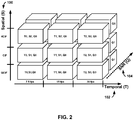
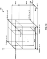
- FIG. 2 is a conceptual illustration showing an example of scalability in three different dimensions.
- scalabilities are enabled in three dimensions.
- the scalabilities are enabled in a spatial (S) dimension 100, a temporal (T) dimension 102, and a signal-to-noise ratio (SNR) or quality (Q) dimension 104.
- SNR signal-to-noise ratio
- Q quality dimension 104.
- frame rates with 7.5 Hz (T0), 15 Hz (T1) or 30 Hz (T2), for example may be supported by temporal scalability.
- S0 When spatial scalability is supported, different resolutions such as QCIF (S0), CIF (S1) and 4CIF (S2), for example, are enabled in the spatial dimension 100.
- SNR layers (Q1) For each specific spatial resolution and frame rate, SNR layers (Q1) can be added in the SNR dimension 104 to improve the picture quality.
- an extractor tool may be used to adapt the actual delivered content according to application requirements, which are dependent e.g., on the clients or the transmission channel.
- each cubic contains pictures with the same frame rate (temporal level), spatial resolution, and SNR layers.
- Better representation may be achieved by adding cubes (i.e., pictures) in any of dimensions 100, 102 or 104. Combined scalability is supported when there are two, three or even more scalabilities enabled.
- the pictures with the lowest spatial and SNR layer are compatible with the single layer video codec, and the pictures at the lowest temporal level form the temporal base layer, which may be enhanced with pictures at higher temporal levels.
- the base layer several spatial and/or SNR enhancement layers may be added to provide spatial and/or quality scalabilities.
- Each spatial or SNR enhancement layer itself may be temporally scalable, with the same temporal scalability structure as the base layer.
- the lower layer it depends on may be referred as the base layer of that specific spatial or SNR enhancement layer.
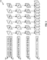
- FIG. 3 is a conceptual illustration showing an example structure 110 of a scalable video coding bitstream.
- the bitstream structure 110 includes a layer 0 112 that includes pictures or slices 10, P4 and P8, and a layer 1 114 that includes pictures or slices B2, B6 and B10.
- bitstream structure 110 includes a layer 2 116 and a layer 3 117 that each includes pictures 0, 2, 4, 6, 8 and 10, and a layer 4 118 that includes pictures 0 through 11.
- a base layer has the lowest spatial and quality layer (i.e., pictures in layer 0 112 and layer 1114 with QCIF resolution). Among them, those pictures of the lowest temporal level form the temporal base layer, as shown in layer 0 112 of FIG. 3 .
- the temporal base layer (layer 0) 112 can be enhanced with pictures of a higher temporal level, e.g., layer 1 114 with frame rate of 15 Hz or layer 4 118 with frame rate of 30 Hz.
- each spatial or SNR enhancement layer itself may be temporally scalable, with the same temporal scalability structure as the base layer 112, 114.
- an enhancement layer may enhance both spatial resolution and frame rate.
- layer 4 118 provides a 4CIF resolution enhancement layer, which further increases the frame rate from 15 Hz to 30 Hz.
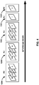
- FIG. 4 is a conceptual illustration showing example scalable video coding access units 120A-120E ("access units 120") in bitstream order.
- the coded pictures or slices in the same time instance are successive in the bitstream order and form one access unit in the context of a scalable video coding standard, such as the SVC extension to H.264 or SHVC.
- the access units 120 then follow the decoding order, which could be different from the display order and determined, for example, by the temporal prediction relationship between access units 120.
- access unit 120A includes picture 10 from layer 0112, picture 0 from layer 2 116, picture 0 from layer 3 117, and picture 0 from layer 4 118.
- Access unit 120B includes picture P4 from layer 0 112, picture 4 from layer 2 116, picture 4 from layer 3 117, and picture 4 from layer 4 118.
- Access unit 120C includes picture B2 from layer 1 114, picture 2 from layer 2 116, picture 2 from layer 3 117, and picture 2 from layer 4 118.
- Access unit 120D includes picture 1 from layer 4 118, and access unit 120E includes picture 3 from layer 4118.
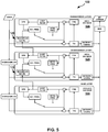
- FIG. 5 is a block diagram illustrating an example 3-layer SHVC encoder 122.
- SHVC encoder 122 includes a base layer encoder 124, a first enhancement layer encoder 125 and a second enhancement layer encoder 126.
- high-level syntax only SHVC, there are no new block level coding tools when compared to HEVC single layer coding.
- SHVC only slice and above level syntax changes and picture level operation, such as picture filtering or up-sampling, are allowed.
- up-sampled co-located reference layer pictures for a lower/base layer may be generated and stored in a reference buffer for a higher/enhancement layer so that inter-layer prediction may be achieved in the same way as inter-frame prediction within a single layer.
- a resampled inter-layer reference (ILR) picture 128 is generated from a reference picture in base layer encoder 124 and stored in first enhancement layer encoder 125.
- a resampled ILR picture 129 is generated from a reference picture in first enhancement layer encoder 125 and stored in second enhancement layer encoder 126.
- the ILR picture is marked as a long term reference picture for the enhancement layer.
- the motion vector difference associated with an inter-layer reference picture is constrained to zero.
- UHDTV ultra-high definition television
- HD uses the BT.709 recommendation, ITU-R Recommendation BT.709 "Parameter values for the HDTV standards for production and international programme exchange" Dec. 2010
- UHDTV will use the BT.2020 recommendation, ITU-R Recommendation BT.2020 "Parameter values for UHDTV systems for production and international programme exchange” April 2012
- a color gamut comprises a complete range of colors that can be reproduced for an image, e.g., in a picture, slice, block or layer of video data.
- a key difference between these systems is that the color gamut of UHDTV is significantly larger than HD. It is asserted that UHDTV will provide a more life-like or realistic viewing experience, which is consistent with other UHDTV characteristics, such as high resolution.
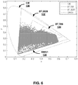
- FIG. 6 is a graph illustrating an example color gamut of a sample video sequence 130.
- the SWG1 sample video sequence 130 is indicated as a cluster of dots within a line outline of the UHD color gamut BT.2020 132.
- an outline of the HD color gamut BT.709 134 and an outline of the International Commission on Illumination (CIE)-XYZ linear color space 136 overlays the SWG1 sample video sequence 130.
- CIE International Commission on Illumination
- FIG. 7 is a block diagram illustrating conversion from HD color gamut BT.709 134 to UHD color gamut BT.2020 132.
- Both the HD color gamut BT.709 134 and the UHD color gamut BT.2020 132 define representations of color pixels in luma and chroma components (e.g., YCbCr or YUV).
- Each color gamut defines conversion to and from the CIE-XYZ linear color space 136.
- This common intermediate color space may be used to define the conversion of the luma and chroma values in the HD color gamut BT.709 134 to corresponding luma and chroma values in the UHD color gamut BT.2020 132.
- JCTVC-L0334 Geneva, CH, 14-23 Jan. 2013 (hereinafter referred to as "JCTVC-L0334").
- a base layer coding loop 142 performs video coding of pictures that include color data in a first color gamut, e.g., BT.709
- an enhancement layer coding loop 146 performs video coding of pictures that include color data in a second color gamut, e.g., BT.2020.
- Color prediction processing unit 144 performs color prediction to map or convert color data of a base layer reference picture in the first color gamut to the second color gamut, and generates an inter-layer reference picture for the enhancement layer based on the mapped color data of the base layer reference picture.
- the prediction parameters knot[c], offset[c], gain1 [c], and gain2[c] may be encoded in the bitstream.
- FIG. 9 is a conceptual illustration showing an example 3D lookup table 150 for color gamut scalability.
- a 3D lookup table based color prediction model is proposed in P. Bordes, P. Andrivon, F. Hiron, "AHG14: Color Gamut Scalable Video Coding using 3D LUT: New Results," JCTVC-N0168, Vienna, Austria, Jul. 2013 (hereinafter referred to as "JCTVC-N0168").
- the principle of the 3D lookup table for color gamut scalability is depicted in FIG. 9 .
- the 3D lookup table 150 can be considered as a subsampling of a first 3D color space, e.g., HD color gamut BT.709, where each vertex is associated with a color triplet (y, u, v) corresponding to second 3D color space (i.e., predicted) values, e.g., UHD color gamut BT.2020).
- a first 3D color space e.g., HD color gamut BT.709
- second 3D color space i.e., predicted
- the first color gamut may be partitioned into octants or cuboids in each color dimension (i.e., Y, U, and V), and the vertices of the octants are associated with the color triplet corresponding to the second color gamut and used to populate 3D lookup table 150.
- the number of vertices or segments in each color dimension indicates the size of 3D lookup table.
- FIG. 9(a) illustrates the vertices or intersecting lattice points of the octants in each color dimension.
- FIG. 9(b) illustrates the different color values associated with each of the vertices. As illustrated, in FIG. 9(a) each color dimension has four vertices and in FIG. 9(b) each color dimension includes four color values.
- a mapping function may be defined for each color component based on the 3D lookup table.
- Y E represents the luma pixel value in the enhancement layer
- (Y B , U B , V B ) represents a base layer pixel value
- LUT Y , LUT U , LUT V and LUT C represent the 3D lookup table for each color component Y, U, V, and a constant.
- Similar mapping functions may be defined for a first chroma (U) pixel value and a second chroma (V) pixel value in the enhancement layer.
- 3D lookup table based color gamut scalability results in good coding performance.
- the size of the 3D lookup table may be concern, however, since the 3D lookup table is typically stored in cache memory in a hardware implementation.
- a 3D lookup table with a large table size may result in high computational complexity and a high signaling cost.
- the 3D lookup tables are always symmetric such that the 3D lookup tables have a same size for the luma component, the first chroma component and the second chroma component.
- the 3D lookup tables are always balanced such that a size of each dimension of the 3D lookup tables is always the same. This results in large table sizes with high computational complexity and high signaling costs.
- table sizes may be up to 9x9x9 or 17x17x17.
- the first method includes generating an asymmetric 3D lookup table such that the luma (Y) and chroma (U and V) components have different sizes.
- the 3D lookup table may have a larger size, i.e., more segments, for the luma component than for each of the first and second chroma components.
- the chroma components may use a coarser lookup table and the luma component may use a more refined lookup table.
- the 3D lookup table may have a larger size for one or both of the chroma components than for the luma component
- the 3D lookup table based color prediction is a kind of 3D piecewise linear prediction.
- the more segments used in each color dimension (i.e., Y, U, and V) of the 3D lookup table the higher the color prediction accuracy.
- a large number of segments, however, may lead to a high signaling cost and high computational complexity (i.e., larger table size).
- the chroma signal may be less important and easier to predict In this case, it may be better to have a high-resolution lookup table for the luma (Y) component and have low-resolution lookup tables for each of the first chroma (U) component and the second chroma (V) component.
- a video coder such as video encoder 20 and/or video decoder 30, may generate the asymmetric 3D lookup table using a different number of segments for the luma dimension of the 3D lookup table than for the first chroma dimension and the second chroma dimension of the 3D lookup table.
- video encoder 20 and/or video decoder 30 may generate the 3D lookup table to have a larger size, i.e., more segments, for the luma component than for each of the first and second chroma components.
- the 3D lookup table may have a size up to 8x2x2.
- the table sizes for the 3D lookup table may be signaled in a bitstream such as in a video parameter set (VPS), sequence parameter set (SPS), picture parameter set (PPS), slice header or related extensions.
- VPS video parameter set
- SPS sequence parameter set
- PPS picture parameter set
- slice header or related extensions.
- each of the 3D lookup tables may have the same size MxNxK, in which the size (M) of the luma dimension of the 3D lookup table is different than the size (N) of the first chroma dimension of the 3D lookup table and the size (K) of the second chroma dimension of the 3D lookup table.
- each of the 3D lookup tables may have the same size of 8x2x2.
- each of the 3D lookup tables may have the same size of 9x6x6.
- a luma component 3D lookup table may have a first size, e.g., MxMxM or MxNxK, that is different than a second size of a first chroma component 3D lookup table (LUT U ), e.g., NxNxN, and a third size of a second chroma component 3D lookup table (LUT V ), e.g., KxKxK.
- the size of the LUT Y may be larger than the sizes of LUT U and LUT V .
- the sizes of LUT U and LUT V may be the same or different from each other.
- LUT Y may have the size 8x2x2, and each of LUT U and LUT V may have the size 2x2x2.
- LUT Y may have the size 9x9x9 or 9x6x6, and each of LUT U and LUT V may have the size 9x3x3 or 3x3x3.
- the precision of the 3D lookup table may be dependent on the associated color component.
- a first precision value of the luma component 3D lookup table may be different than a second precision value of both the first and second chroma component 3D lookup tables.
- the first precision value of the luma component 3D lookup table may be higher than the second precision value of the chroma component 3D lookup tables.
- the first precision value may be 8-bit for the luma component and the second precision value may be 6-bit for the chroma components.
- an additional shift may be applied in order to meet a target bit depth of the enhancement layer.
- the use of different precision values from a default precision value for 3D lookup tables based on the associated color component may be indicated in the VPS, SPS, PPS, slice header or related extensions.
- the 3D lookup table proposed in JCTVC-N0168 is always balanced such that the size of each dimension of the 3D lookup table is always same.
- the more segments used in each color dimension (i.e. Y, U, and V) of the 3D lookup table the better the color prediction efficiency.
- a large number of segments may lead to a high signaling cost and high computational complexity (i.e., larger table size).
- each color component in a first color gamut usually has higher correlation with the same color component in a second color gamut, it may be more helpful to improve the prediction efficiency by using more segments, i.e. using a larger size, for the table dimension when the associated color component is used as a table index for the 3D lookup table.
- the size of the table dimension may be smaller when a different color component is used as a table index for the 3D lookup table.
- a video coder such as video encoder 20 and/or video decoder 30, may generate the unbalanced 3D lookup table using more segments for the dimension of the 3D lookup table associated with the color component used as a table index for the 3D lookup table.
- the luma component 3D lookup table may have a larger luma dimension than a first chroma dimension and a second chroma dimension based on the luma component being used as a table index for the luma component 3D lookup table.
- the LUT Y may have the size MxNxN, where M > N. The sizes of the first and second chroma component 3D lookup tables may be similarly determined.
- the LUT U may have the size NxMxN based on the first chroma component being used at the table index
- the LUT v may have the size NxNxM based on the second chroma component being used at the table index. In this way, the total size of each of the tables may be reduced while maintaining good coding performance with higher resolution for the color component used as the table index.
- an 8x2x2 table may be used for the Y component
- a 2x8x2 table may be used for the U component
- a 2x2x8 table may be used for the V component.
- a 9x3x3 table may be used for the Y component
- a 3x9x3 table may be used for the U component
- a 3x3x9 table may be used for the V component.
- the table sizes for the 3D lookup table may be signaled in a bitstream such as in the VPS, SPS, PPS, slice header or related extensions.
- a bitstream such as in the VPS, SPS, PPS, slice header or related extensions.
- M and N may be signaled to indicate the table sizes.
- default values may be set for M and N so that no signaling of the table size is needed. For example, N may be set to a value of 3 or a value of 2 by default.
- FIG. 11 is a block diagram illustrating an example of video encoder 20 that may implement techniques for using 3D lookup table based color gamut scalability in multi-layer video coding.
- Video encoder 20 may perform intra- and inter-coding of video blocks within video slices.
- Intra-coding relies on spatial prediction to reduce or remove spatial redundancy in video within a given video frame or picture.
- Inter-coding relies on temporal prediction to reduce or remove temporal redundancy in video within adjacent frames or pictures of a video sequence.
- Intra-mode (I mode) may refer to any of several spatial based coding modes.
- Inter-modes, such as uni-directional prediction (P mode) or bi-prediction (B mode) may refer to any of several temporal-based coding modes.
- video encoder 20 receives a current video block within a video frame to be encoded.
- video encoder 20 includes mode select unit 40, a video data memory 41, decoded picture buffer 64, summer 50, transform processing unit 52, quantization unit 54, and entropy encoding unit 56.
- Mode select unit 40 includes motion compensation unit 44, motion estimation unit 42, intra-prediction unit 46, partition unit 48, and color prediction processing unit 66.
- video encoder 20 also includes inverse quantization unit 58, inverse transform processing unit 60, and summer 62.
- a deblocking filter (not shown in FIG. 11 ) may also be included to filter block boundaries to remove blockiness artifacts from reconstructed video.
- the deblocking filter would typically filter the output of summer 62. Additional filters (in loop or post loop) may also be used in addition to the deblocking filter. Such filters are not shown for brevity, but if desired, may filter the output of summer 50 (as an in-loop filter).
- Video data memory 41 may store video data to be encoded by the components of video encoder 20.
- the video data stored in video data memory 41 may be obtained, for example, from video source 18.
- Decoded picture buffer 64 may be a reference picture memory that stores reference video data for use in encoding video data by video encoder 20, e.g., in intra- or inter-coding modes.
- Video data memory 41 and decoded picture buffer 64 may be formed by any of a variety of memory devices, such as dynamic random access memory (DRAM), including synchronous DRAM (SDRAM), magnetoresistive RAM (MRAM), resistive RAM (RRAM), or other types of memory devices.
- Video data memory 41 and decoded picture buffer 64 may be provided by the same memory device or separate memory devices.
- video data memory 41 may be on-chip with other components of video encoder 20, or off-chip relative to those components.
- video encoder 20 receives a video frame or slice to be coded.
- the frame or slice may be divided into multiple video blocks.
- Motion estimation unit 42 and motion compensation unit 44 perform inter-predictive coding of the received video block relative to one or more blocks in one or more reference frames to provide temporal prediction.
- Intra-prediction unit 46 may alternatively perform intra-predictive coding of the received video block relative to one or more neighboring blocks in the same frame or slice as the block to be coded to provide spatial prediction.
- Video encoder 20 may perform multiple coding passes, e.g., to select an appropriate coding mode for each block of video data.
- partition unit 48 may partition blocks of video data into sub-blocks, based on evaluation of previous partitioning schemes in previous coding passes. For example, partition unit 48 may initially partition a frame or slice into LCUs, and partition each of the LCUs into sub-CUs based on rate-distortion analysis (e.g., rate-distortion optimization). Mode select unit 40 may further produce a quadtree data structure indicative of partitioning of an LCU into sub-CUs. Leaf-node CUs of the quadtree may include one or more PUs and one or more TUs.
- Mode select unit 40 may select one of the coding modes, intra or inter, e.g., based on error results, and provides the resulting intra- or inter-coded block to summer 50 to generate residual block data and to summer 62 to reconstruct the encoded block for use as a reference frame. Mode select unit 40 also provides syntax elements, such as motion vectors, intra-mode indicators, partition information, and other such syntax information, to entropy encoding unit 56.
- video encoder 20 may calculate values for sub-integer pixel positions of reference pictures stored in decoded picture buffer 64. For example, video encoder 20 may interpolate values of one-quarter pixel positions, one-eighth pixel positions, or other fractional pixel positions of the reference picture. Therefore, motion estimation unit 42 may perform a motion search relative to the full pixel positions and fractional pixel positions and output a motion vector with fractional pixel precision.
- Intra-prediction unit 46 may intra-predict a current block, as an alternative to the inter-prediction performed by motion estimation unit 42 and motion compensation unit 44, as described above. In particular, intra-prediction unit 46 may determine an intra-prediction mode to use to encode a current block. In some examples, intra-prediction unit 46 may encode a current block using various intra-prediction modes, e.g., during separate encoding passes, and intra-prediction unit 46 (or mode select unit 40, in some examples) may select an appropriate intra-prediction mode to use from the tested modes.
- Video encoder 20 forms a residual video block by subtracting the prediction data from mode select unit 40 from the original video block being coded.
- Summer 50 represents the component or components that perform this subtraction operation.
- Transform processing unit 52 applies a transform, such as a discrete cosine transform (DCT) or a conceptually similar transform, to the residual block, producing a video block comprising residual transform coefficient values.
- Transform processing unit 52 may perform other transforms which are conceptually similar to DCT. Wavelet transforms, integer transforms, sub-band transforms or other types of transforms could also be used.
- transform processing unit 52 applies the transform to the residual block, producing a block of residual transform coefficients.
- the transform may convert the residual information from a pixel value domain to a transform domain, such as a frequency domain.
- Transform processing unit 52 may send the resulting transform coefficients to quantization unit 54.
- Quantization unit 54 quantizes the transform coefficients to further reduce bit rate. The quantization process may reduce the bit depth associated with some or all of the coefficients. The degree of quantization may be modified by adjusting a quantization parameter.
- quantization unit 54 may then perform a scan of the matrix including the quantized transform coefficients. Alternatively, entropy encoding unit 56 may perform the scan.
- entropy encoding unit 56 entropy codes the quantized transform coefficients.
- entropy encoding unit 56 may perform context adaptive variable length coding (CAVLC), context adaptive binary arithmetic coding (CABAC), syntax-based context-adaptive binary arithmetic coding (SBAC), probability interval partitioning entropy (PIPE) coding or another entropy coding technique.
- context may be based on neighboring blocks.
- the encoded bitstream may be transmitted to another device (e.g., video decoder 30) or archived for later transmission or retrieval.
- Inverse quantization unit 58 and inverse transform processing unit 60 apply inverse quantization and inverse transformation, respectively, to reconstruct the residual block in the pixel domain, e.g., for later use as a reference block.
- Motion compensation unit 44 may calculate a reference block by adding the residual block to a predictive block of one of the frames of decoded picture buffer 64. Motion compensation unit 44 may also apply one or more interpolation filters to the reconstructed residual block to calculate sub-integer pixel values for use in motion estimation.
- Summer 62 adds the reconstructed residual block to the motion compensated prediction block produced by motion compensation unit 44 to produce a reconstructed video block for storage in decoded picture buffer 64.
- the reconstructed video block may be used by motion estimation unit 42 and motion compensation unit 44 as a reference block to inter-code a block in a subsequent video frame.
- video encoder 20 is configured to perform 3D lookup table based color gamut scalability when encoding multi-layer video data.
- Video encoder 20 may predict and encode multi-layer video data in accordance any of the SHVC extension, the MV-HEVC extension, and the 3D-HEVC extension, or other multi-layer video coding extensions.
- color prediction processing unit 66 of video encoder 20 may generate inter-layer reference pictures used to predict video blocks in a picture of a higher layer of the video data when a color gamut for the higher layer of the video data is different than a color gamut for a lower layer of video data.
- Color prediction processing unit 66 of video encoder 20 may perform color prediction using a 3D lookup table for color gamut scalability to convert color data of a reference picture in a first color gamut for the lower layer of the video data to a second color gamut for the higher layer of the video data.
- color prediction processing unit 66 may generate a separate 3D lookup table may be generated for each of the color components, i.e., a luma component, a first chroma component and a second chroma component
- Each of the 3D lookup tables includes a luma dimension, a first chroma dimension and a second chroma dimension, and is indexed using the three independent color components.
- color prediction processing unit 66 may generate each of the 3D lookup tables to have the same size, in which a size of the luma dimension of the 3D lookup table is different than each of a size of the first chroma dimension of the 3D lookup table and a size of the second chroma dimension of the 3D lookup table. In other examples, color prediction processing unit 66 may generate a luma component 3D lookup table to have a first size that is different than each of a second size of a first chroma component 3D lookup table and a third size of a second chroma component 3D lookup table.
- color prediction processing unit 66 may generate a luma component 3D lookup table to have a different precision value than each of the first chroma component 3D lookup table and the second chroma component 3D lookup table. In some cases, to further reduce complexity, color prediction processing unit 66 may only generate a luma component 3D lookup table, perform luma component prediction using the luma component 3D lookup table, and perform first and second chroma component prediction using 1D linear mapping or piecewise linear mapping.
- color prediction processing unit 66 may generate an unbalanced 3D lookup table using more segments for the dimension of the 3D lookup table associated with the color component used as a table index for the 3D lookup table.
- the luma component 3D lookup table may have a larger luma dimension than each of a first chroma dimension and a second chroma dimension based on the luma component being used as a table index for the luma component 3D lookup table.
- the sizes of the first and second chroma component 3D lookup tables may be similarly determined based on the respective one of the first or second chroma component being used at the table index. In this way, the total size of each of the tables may be reduced while maintaining good coding performance with higher resolution for the color component used as the table index.
- color prediction processing unit 66 Upon generating the 3D lookup table, color prediction processing unit 66 performs color prediction of a reference picture for the lower layer of the video data using the 3D lookup table, and generates an inter-layer reference picture for the higher layer of the video data based on the color predicted reference picture.
- motion compensation unit 44 of video encoder 20 may operate as described above to predict video blocks in a picture of the higher layer of the video data based on the inter-layer reference pictures generated using the 3D lookup table.
- Video encoder 20 may then encode residual data of the predicted video blocks in a bitstream for transmission to video decoder 30.
- video encoder 20 may also encode one or more syntax elements indicating the size of the 3D lookup table in the bitstream, where the size is different for the luma component than for the first and second chroma components.
- Video data memory 71 and decoded picture buffer 82 may be formed by any of a variety of memory devices, such as dynamic random access memory (DRAM), including synchronous DRAM (SDRAM), magnetoresistive RAM (MRAM), resistive RAM (RRAM), or other types of memory devices. Video data memory 71 and decoded picture buffer 82 may be provided by the same memory device or separate memory devices. In various examples, video data memory 71 may be on-chip with other components of video decoder 30, or off-chip relative to those components.
- DRAM dynamic random access memory
- SDRAM synchronous DRAM
- MRAM magnetoresistive RAM
- RRAM resistive RAM
- Motion compensation unit 72 determines prediction information for a video block of the current video slice by parsing the motion vectors and other syntax elements, and uses the prediction information to produce the predictive blocks for the current video block being decoded. For example, motion compensation unit 72 uses some of the received syntax elements to determine a prediction mode (e.g., intra- or inter-prediction) used to code the video blocks of the video slice, an inter-prediction slice type (e.g., B slice or P slice), construction information for one or more of the reference picture lists for the slice, motion vectors for each inter-encoded video block of the slice, inter-prediction status for each inter-coded video block of the slice, and other information to decode the video blocks in the current video slice.
- a prediction mode e.g., intra- or inter-prediction
- an inter-prediction slice type e.g., B slice or P slice
- construction information for one or more of the reference picture lists for the slice motion vectors for each inter-encoded video block of the slice, inter-prediction status
- video decoder 30 forms a decoded video block by summing the residual blocks from inverse transform processing unit 78 with the corresponding predictive blocks generated by motion compensation unit 72.
- Summer 80 represents the component or components that perform this summation operation.
- a deblocking filter may also be applied to filter the decoded blocks in order to remove blockiness artifacts.
- Other loop filters may also be used to smooth pixel transitions, or otherwise improve the video quality.
- the decoded video blocks in a given frame or picture are then stored in decoded picture buffer 82, which stores reference pictures used for subsequent motion compensation.
- Decoded picture buffer 82 also stores decoded video for later presentation on a display device, such as display device 32 of FIG. 1 .
- Color prediction processing unit 86 of video decoder 30 may perform color prediction using a 3D lookup table for color gamut scalability to convert color data of a reference picture in a first color gamut for the lower layer of the video data to a second color gamut for the higher layer of the video data.
- color prediction processing unit 86 may generate a separate 3D lookup table may be generated for each of the color components, i.e., a luma component, a first chroma component and a second chroma component.
- Each of the 3D lookup tables includes a luma dimension, a first chroma dimension and a second chroma dimension, and is indexed using the three independent color components.
- color prediction processing unit 86 of video decoder 30 generates at least one 3D lookup table having a size that is different for the luma component than for each of the first chroma component and the second chroma component.
- video decoder 30 may decode one or more syntax elements indicating the size of the 3D lookup table in the bitstream, where the size is different for the luma component than for the first and second chroma components.
- Color prediction processing unit 86 may generate this asymmetric 3D lookup table according to the indicated size using a different number of segments for the luma dimension of the 3D lookup table.
- color prediction processing unit 86 may generate each of the 3D lookup tables to have the same size, in which a size of the luma dimension of the 3D lookup table is different than each of a size of the first chroma dimension of the 3D lookup table and a size of the second chroma dimension of the 3D lookup table. In other examples, color prediction processing unit 86 may generate a luma component 3D lookup table to have a first size that is different than each of a second size of a first chroma component 3D lookup table and a third size of a second chroma component 3D lookup table.
- color prediction processing unit 86 may generate an unbalanced 3D lookup table using more segments for the dimension of the 3D lookup table associated with the color component used as a table index for the 3D lookup table.
- the luma component 3D lookup table may have a larger luma dimension than each of a first chroma dimension and a second chroma dimension based on the luma component being used as a table index for the luma component 3D lookup table.
- the sizes of the first and second chroma component 3D lookup tables may be similarly determined based on the respective one of the first or second chroma component being used at the table index. In this way, the total size of each of the tables may be reduced while maintaining good coding performance with higher resolution for the color component used as the table index.
- a lower layer of video data e.g., a base layer
- a higher layer of the video data e.g., an enhancement layer
- a video decoder may generate inter-layer reference pictures for the higher layer of the video data as up-sampled versions of co-located reference pictures for the lower layer of the video data.
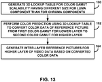
- color prediction processing unit 86 generates at least one 3D lookup table for color gamut scalability having a different size for a luma component than for each of a first chroma component and a second chroma component (180).
- Entropy decoding unit 70 may decode one or more syntax elements indicating the size of the at least one 3D lookup table, where the size is different for the luma component than for each of the first and second chroma components.
- Color prediction processing unit 86 may generate this asymmetric 3D lookup table according to the indicated size by using a different number of segments for the luma dimension of the 3D lookup table than for the first and second chroma components of the 3D lookup table.
- color prediction processing unit 86 may generate the 3D lookup table to have a larger size, i.e., more segments, for the luma component than for each of the first and second chroma components.
- the 3D lookup table may have a size up to 8x2x2. In this way, the total size of the table may be reduced while maintaining good coding performance with higher resolution for the luma component than for the first and second chroma components.
- Color prediction processing unit 86 may generate a separate 3D lookup table for each of the color components, i.e., a luma (Y) component, a first chroma (U) component and a second chroma (V) component.
- Each of the 3D lookup tables includes a luma (Y) dimension, a first chroma (U) dimension and a second chroma (V) dimension, and is indexed using the three independent color components (Y, U, V).
- color prediction processing unit 86 may generate a luma component 3D lookup table (LUT Y ) to have a first size, e.g., MxMxM or MxNxK, that is different than each of a second size of a first chroma component 3D lookup table (LUT U ), e.g., NxNxN, and a third size of a second chroma component 3D lookup table (LUT V ), e.g., KxKxK.
- the size of the luma component 3D lookup table may be larger than the sizes of the chroma component 3D lookup tables.
- the first and second chroma component 3D lookup tables may be the same size or different sizes.
- LUT Y may have the size 8x2x2, and each of LUT U and LUT V may have the size 2x2x2.
- color prediction processing unit 86 of video decoder 30 may generate the at least one 3D lookup table as an unbalanced 3D lookup table using more segments for the dimension of the 3D lookup table associated with the color component used as a table index for the 3D lookup table.
- the luma component 3D lookup table may have a larger luma dimension than a first chroma dimension and a second chroma dimension based on the luma component being used as a table index for the luma component 3D lookup table.
- the LUT Y may have the size MxNxN, where M > N. The sizes of the first and second chroma component 3D lookup tables may be similarly determined.
- the LUT U may have the size NxMxN based on the first chroma component being used at the table index
- the LUT V may have the size NxNxM based on the second chroma component being used at the table index. In this way, the total size of each of the tables may be reduced while maintaining good coding performance with higher resolution for the color component used as the table index.
- color prediction processing unit 86 After generating the at least one 3D lookup table, color prediction processing unit 86 performs color prediction using the at least one 3D lookup table to convert the color data of the reference picture in the first color gamut for the lower layer of the video data to the second color gamut for the higher layer of the video data (182). Color prediction processing unit 86 then generates at least one inter-layer reference picture for the higher layer of the video data based on the converted color data (184). In cases where only a luma component 3D lookup table is generated, color prediction processing unit 86 may perform luma component prediction using the luma component 3D lookup table, and perform first and second chroma component prediction using 1D linear mapping or piecewise linear mapping to generate an inter-layer reference picture. Video decoder 30 may then reconstruct predicted video blocks in a picture of the higher layer of video data based on decoded residual data and the at least one inter-layer reference picture generated using the at least one 3D lookup table.
- a video coder may refer to a video encoder or a video decoder.
- a video coding unit may refer to a video encoder or a video decoder.
- video coding may refer to video encoding or video decoding, as applicable.
- Computer-readable media may include computer-readable storage media, which corresponds to a tangible medium such as data storage media, or communication media including any medium that facilitates transfer of a computer program from one place to another, e.g., according to a communication protocol.
- Computer-readable media generally may correspond to (1) tangible computer-readable storage media which is non-transitory or (2) a communication medium such as a signal or carrier wave.
- Data storage media may be any available media that can be accessed by one or more computers or one or more processors to retrieve instructions, code and/or data structures for implementation of the techniques described in this disclosure.
- a computer program product may include a computer-readable medium.
- such computer-readable storage media can comprise RAM, ROM, EEPROM, CD-ROM or other optical disk storage, magnetic disk storage, or other magnetic storage devices, flash memory, or any other medium that can be used to store desired program code in the form of instructions or data structures and that can be accessed by a computer.
- any connection is properly termed a computer-readable medium.
- a computer-readable medium For example, if instructions are transmitted from a website, server, or other remote source using a coaxial cable, fiber optic cable, twisted pair, digital subscriber line (DSL), or wireless technologies such as infrared, radio, and microwave, then the coaxial cable, fiber optic cable, twisted pair, DSL, or wireless technologies such as infrared, radio, and microwave are included in the definition of medium.
- DSL digital subscriber line
- Disk and disc includes compact disc (CD), laser disc, optical disc, digital versatile disc (DVD), floppy disk and Blu-ray disc, where disks usually reproduce data magnetically, while discs reproduce data optically with lasers. Combinations of the above should also be included within the scope of computer-readable media.
- processors such as one or more digital signal processors (DSPs), general purpose microprocessors, application specific integrated circuits (ASICs), field programmable logic arrays (FPGAs), or other equivalent integrated or discrete logic circuitry.
- DSPs digital signal processors
- ASICs application specific integrated circuits
- FPGAs field programmable logic arrays
- processors may refer to any of the foregoing structure or any other structure suitable for implementation of the techniques described herein.
- the functionality described herein may be provided within dedicated hardware and/or software modules configured for encoding and decoding, or incorporated in a combined codec. Also, the techniques could be fully implemented in one or more circuits or logic elements.
- the techniques of this disclosure may be implemented in a wide variety of devices or apparatuses, including a wireless handset, an integrated circuit (IC) or a set of ICs (e.g., a chip set).
- IC integrated circuit
- a set of ICs e.g., a chip set.
- Various components, modules, or units are described in this disclosure to emphasize functional aspects of devices configured to perform the disclosed techniques, but do not necessarily require realization by different hardware units. Rather, as described above, various units may be combined in a codec hardware unit or provided by a collection of interoperative hardware units, including one or more processors as described above, in conjunction with suitable software and/or firmware.
Claims (6)
- Verfahren zum Verarbeiten von mehrschichtigen Videodaten, wobei das Verfahren Folgendes beinhaltet:Erzeugen einer Mehrzahl von dreidimensionalen (3D) Lookup-Tabellen für Farbraumskalierbarkeit, wobei die Mehrzahl von 3D-Lookup-Tabellen eine erste Lookup-Tabelle für eine Luma-Komponente und eine zweite Lookup-Tabelle für eine erste Chroma-Komponente und eine dritte Lookup-Tabelle für eine zweite Chroma-Komponente umfasst, wobei jede aus der ersten Lookup-Tabelle und der zweiten Lookup-Tabelle und der dritten Lookup-Tabelle 3 Dimensionen umfasst, die eine Luma-Dimension und eine erste Chroma-Dimension und eine zweite Chroma-Dimension umfassen, und wobei die 3D-Lookup-Tabelle für die Luma-Komponente größer ist als die 3D-Lookup-Tabelle für die erste Chroma-Komponente, und wobei die 3D-Lookup-Tabelle für die erste Chroma-Komponente genauso groß ist wie die 3D-Lookup-Tabelle für die zweite Chroma-Komponente, und wobei die Luma-Dimension jeder 3D-Lookup-Tabelle größer ist als die erste Chroma-Dimension und die zweite Chroma-Dimension;Codieren einer Mehrzahl von Syntaxelementen, die die Größen für die 3D-Lookup-Tabellen anzeigen;Durchführen von Farbprädiktion anhand der wenigstens einen 3D-Lookup-Tabelle, um Farbdaten eines Referenzbildes in einem ersten Farbraum für eine tiefere Schicht der Videodaten in einen zweiten Farbraum für eine höhere Schicht der Videodaten auf der Basis der codierten Syntaxelemente umzuwandeln; undErzeugen wenigstens eines Inter-Schicht-Referenzbildes für die höhere Schicht der Videodaten auf der Basis der umgewandelten Farbdaten.
- Verfahren nach Anspruch 1, wobei das Erzeugen der Mehrzahl von 3D-Lookup-Tabellen ferner das Erzeugen einer Luma-Komponenten-3D-Lookup-Tabelle mit einem ersten Präzisionswert, das Erzeugen einer ersten Chroma-Komponenten-3D-Lookup-Tabelle mit einem zweiten Präzisionswert und das Erzeugen einer zweiten Chroma-Komponenten-3D-Lookup-Tabelle mit dem zweiten Präzisionswert beinhaltet, wobei sich der erste Präzisionswert vom zweiten Präzisionswert unterscheidet.
- Verfahren nach Anspruch 1, das ferner Folgendes beinhaltet:Prädizieren von Videoblöcken in einem Bild der höheren Schicht der Videodaten auf der Basis des wenigstens einen anhand der wenigstens einen 3D-Lookup-Tabelle erzeugten Inter-Schicht-Referenzbildes;Encodieren von Restdaten der prädizierten Videoblöcke in einem Bitstrom; undEncodieren von einem oder mehreren Syntaxelementen, die die Größe der wenigstens einen 3D-Lookup-Tabelle in dem Bitstrom anzeigen, wobei die ein oder mehreren Syntaxelemente anzeigen, dass sich die Größe für die Luma-Komponente von der der ersten und zweiten Chroma-Komponenten unterscheidet.
- Verfahren nach Anspruch 1, das ferner Folgendes beinhaltet:Decodieren von einem oder mehreren Syntaxelementen, die die Größe der wenigstens einen 3D-Lookup-Tabelle anzeigen, wobei die ein oder mehreren Syntaxelemente anzeigen, dass sich die Größe für die Luma-Komponente von der der ersten und zweiten Chroma-Komponente unterscheidet;Decodieren von Restdaten von prädizierten Videoblöcken; undRekonstruieren der prädizierten Videoblöcke in einem Bild der höheren Schicht der Videodaten auf der Basis der decodierten Restdaten und des wenigstens einen anhand von wenigstens einer 3D-Lookup-Tabelle erzeugten Inter-Schicht-Referenzbildes.
- Videoverarbeitungsgerät zum Verarbeiten von mehrschichtigen Videodaten, wobei das Gerät Folgendes umfasst:Mittel zum Erzeugen einer Mehrzahl von dreidimensionalen (3D) Lookup-Tabellen für Farbraumskalierbarkeit, wobei die Mehrzahl von 3D-Lookup-Tabellen eine erste Lookup-Tabelle für eine Luma-Komponente und eine zweite Lookup-Tabelle für eine erste Chroma-Komponente und eine dritte Lookup-Tabelle für eine zweite Chroma-Komponente umfasst, wobei jede aus erster Lookup-Tabelle und zweiter Lookup-Tabelle und dritter Lookup-Tabelle 3 Dimensionen umfasst, die eine Luma-Dimension und eine erste Chroma-Dimension und eine zweite Chroma-Dimension umfassen, und wobei die 3D-Lookup-Tabelle für die Luma-Komponente größer ist als die 3D-Lookup-Tabelle für die erste Chroma-Komponente, und wobei die 3D-Lookup-Tabelle für die erste Chroma-Komponente genauso groß ist wie die 3D-Lookup-Tabelle für die zweite Chroma-Komponente, und wobei die Luma-Dimension jeder 3D-Lookup-Tabelle größer ist als die erste Chroma-Dimension und die zweite Chroma-Dimension;Mittel zum Codieren einer Mehrzahl von Syntaxelementen, die die Größen für die 3D-Lookup-Tabellen anzeigen;Mittel zum Durchführen von Farbprädiktion anhand der wenigstens einen 3D-Lookup-Tabelle, um Farbdaten eines Referenzbildes in einem ersten Farbraum für eine tiefere Schicht der Videodaten in einen zweiten Farbraum für eine höhere Schicht der Videodaten auf der Basis der codierten Syntaxelemente umzuwandeln; undMittel zum Erzeugen von wenigstens einem Inter-Schicht-Referenzbild für die höhere Schicht der Videodaten auf der Basis der umgewandelten Farbdaten.
- Computerlesbares Speichermedium, auf dem Befehle zum Verarbeiten von mehrschichtigen Videodaten gespeichert sind, die bei Ausführung bewirken, dass ein oder mehrere Prozessoren das Verfahren nach einem der Ansprüche 1 bis 4 durchführen.
Applications Claiming Priority (3)
| Application Number | Priority Date | Filing Date | Title |
|---|---|---|---|
| US201361890843P | 2013-10-14 | 2013-10-14 | |
| US14/512,177 US9948916B2 (en) | 2013-10-14 | 2014-10-10 | Three-dimensional lookup table based color gamut scalability in multi-layer video coding |
| PCT/US2014/060413 WO2015057656A1 (en) | 2013-10-14 | 2014-10-14 | Three-dimensional lookup table based color gamut scalability in multi-layer video coding |
Publications (2)
| Publication Number | Publication Date |
|---|---|
| EP3058731A1 EP3058731A1 (de) | 2016-08-24 |
| EP3058731B1 true EP3058731B1 (de) | 2019-08-07 |
Family
ID=52809631
Family Applications (1)
| Application Number | Title | Priority Date | Filing Date |
|---|---|---|---|
| EP14792941.8A Active EP3058731B1 (de) | 2013-10-14 | 2014-10-14 | Auf dreidimensionaler nachschlagetabelle basierte farbtonskalierbarkeit in mehrschichtiger videocodierung |
Country Status (10)
| Country | Link |
|---|---|
| US (1) | US9948916B2 (de) |
| EP (1) | EP3058731B1 (de) |
| JP (2) | JP2016537929A (de) |
| KR (1) | KR102276273B1 (de) |
| CN (1) | CN105659595B (de) |
| BR (1) | BR112016008224B1 (de) |
| CA (1) | CA2925909C (de) |
| ES (1) | ES2753960T3 (de) |
| HU (1) | HUE046838T2 (de) |
| WO (1) | WO2015057656A1 (de) |
Families Citing this family (21)
| Publication number | Priority date | Publication date | Assignee | Title |
|---|---|---|---|---|
| WO2013109026A1 (ko) * | 2012-01-18 | 2013-07-25 | 엘지전자 주식회사 | 엔트로피 부호화/복호화 방법 및 그 장치 |
| US9602841B2 (en) * | 2012-10-30 | 2017-03-21 | Texas Instruments Incorporated | System and method for decoding scalable video coding |
| US10531105B2 (en) | 2013-12-17 | 2020-01-07 | Qualcomm Incorporated | Signaling partition information for 3D lookup table for color gamut scalability in multi-layer video coding |
| US9756337B2 (en) | 2013-12-17 | 2017-09-05 | Qualcomm Incorporated | Signaling color values for 3D lookup table for color gamut scalability in multi-layer video coding |
| US9445111B2 (en) * | 2014-01-08 | 2016-09-13 | Sony Corporation | Image processing apparatus and image processing method |
| EP3105926B1 (de) * | 2014-02-13 | 2018-04-11 | Dolby International AB | Stückweise zwischenschichtvorhersage für signale mit verbessertem dynamikbereich |
| US10448029B2 (en) | 2014-04-17 | 2019-10-15 | Qualcomm Incorporated | Signaling bit depth values for 3D color prediction for color gamut scalability |
| JP6330507B2 (ja) * | 2014-06-19 | 2018-05-30 | ソニー株式会社 | 画像処理装置及び画像処理方法 |
| US20160217766A1 (en) * | 2015-01-23 | 2016-07-28 | Dell Products, Lp | System and Method for Sub-Pixel Color Management |
| US10257526B2 (en) * | 2015-05-01 | 2019-04-09 | Disney Enterprises, Inc. | Perceptual color transformations for wide color gamut video coding |
| MX359573B (es) | 2015-05-15 | 2018-09-24 | Hewlett Packard Development Co | Cartuchos de impresion y dispositivos de memoria que contienen tablas de color multidimensionales comprimidas. |
| US10244245B2 (en) * | 2015-06-08 | 2019-03-26 | Qualcomm Incorporated | Content-adaptive application of fixed transfer function to high dynamic range (HDR) and/or wide color gamut (WCG) video data |
| US10321162B2 (en) * | 2015-06-08 | 2019-06-11 | Qualcomm Incorporated | Derivation of color gamut scalability parameters and tables in scalable video coding |
| US10674043B2 (en) | 2016-07-08 | 2020-06-02 | Hewlett-Packard Development Company, L.P. | Color table compression |
| US9992382B2 (en) | 2016-07-08 | 2018-06-05 | Hewlett-Packard Development Company, L.P. | Color table compression |
| CA3027338C (en) | 2016-07-08 | 2019-10-22 | Hewlett-Packard Development Company, L.P. | Color look up table compression |
| US11178204B1 (en) * | 2017-02-23 | 2021-11-16 | Cox Communications, Inc. | Video processor to enhance color space and/or bit-depth |
| CN110636299B (zh) * | 2018-06-21 | 2022-06-14 | 北京字节跳动网络技术有限公司 | 用于处理视频数据的方法、装置及计算机可读记录介质 |
| CN109005408B (zh) * | 2018-08-01 | 2020-05-29 | 北京奇艺世纪科技有限公司 | 一种帧内预测方法、装置及电子设备 |
| CN109685859B (zh) * | 2018-12-24 | 2021-06-08 | 哈尔滨工业大学(深圳) | 基于3d查找表的三维颜色自动调整方法 |
| US11234023B2 (en) * | 2019-06-28 | 2022-01-25 | Microsoft Technology Licensing, Llc | Features of range asymmetric number system encoding and decoding |
Family Cites Families (16)
| Publication number | Priority date | Publication date | Assignee | Title |
|---|---|---|---|---|
| KR100547812B1 (ko) * | 2002-06-24 | 2006-01-31 | 삼성전자주식회사 | 컬러 참조테이블을 사용하여 화소데이터의 컬러모델을변환하는 장치 및 방법 |
| US7653133B2 (en) | 2003-06-10 | 2010-01-26 | Rensselaer Polytechnic Institute (Rpi) | Overlapped block motion compression for variable size blocks in the context of MCTF scalable video coders |
| US8014445B2 (en) | 2006-02-24 | 2011-09-06 | Sharp Laboratories Of America, Inc. | Methods and systems for high dynamic range video coding |
| US8761249B2 (en) | 2006-07-17 | 2014-06-24 | Thomson Licensing | Method and apparatus for encoding video color enhancement data, and method and apparatus for decoding video color enhancement data |
| CN101589625B (zh) * | 2006-10-25 | 2011-09-21 | 弗劳恩霍夫应用研究促进协会 | 质量可缩放编码 |
| US7843465B1 (en) * | 2007-05-31 | 2010-11-30 | Zoran Corporation | Method and apparatus for mapping a multi-dimensional signal from one space to another space |
| EP2051527A1 (de) * | 2007-10-15 | 2009-04-22 | Thomson Licensing | Verstärkungsschichtrestvorhersage für die Bittiefenskalierbarkeit mittel hierarchischer LUTs |
| US8208560B2 (en) | 2007-10-15 | 2012-06-26 | Intel Corporation | Bit depth enhancement for scalable video coding |
| JP2011040001A (ja) * | 2009-08-18 | 2011-02-24 | Nec Personal Products Co Ltd | 画像処理装置、画像処理方法及びプログラム |
| WO2012122425A1 (en) | 2011-03-10 | 2012-09-13 | Dolby Laboratories Licensing Corporation | Bitdepth and color scalable video coding |
| WO2012147010A1 (en) | 2011-04-28 | 2012-11-01 | Koninklijke Philips Electronics N.V. | Method and apparatus for generating an image coding signal |
| WO2015042432A1 (en) | 2013-09-20 | 2015-03-26 | Vid Scale, Inc | Systems and methods for providing 3d look-up table coding for color gamut scalability |
| CN105874793B (zh) | 2013-10-07 | 2019-10-11 | Vid拓展公司 | 用于多层视频编码的组合可分级性处理的方法和设备 |
| CN108337519B (zh) | 2013-12-13 | 2021-12-03 | Vid拓展公司 | 视频编码设备及方法 |
| US10531105B2 (en) | 2013-12-17 | 2020-01-07 | Qualcomm Incorporated | Signaling partition information for 3D lookup table for color gamut scalability in multi-layer video coding |
| US9756337B2 (en) | 2013-12-17 | 2017-09-05 | Qualcomm Incorporated | Signaling color values for 3D lookup table for color gamut scalability in multi-layer video coding |
-
2014
- 2014-10-10 US US14/512,177 patent/US9948916B2/en active Active
- 2014-10-14 EP EP14792941.8A patent/EP3058731B1/de active Active
- 2014-10-14 ES ES14792941T patent/ES2753960T3/es active Active
- 2014-10-14 BR BR112016008224-9A patent/BR112016008224B1/pt active IP Right Grant
- 2014-10-14 JP JP2016547991A patent/JP2016537929A/ja active Pending
- 2014-10-14 CN CN201480056166.3A patent/CN105659595B/zh active Active
- 2014-10-14 CA CA2925909A patent/CA2925909C/en active Active
- 2014-10-14 WO PCT/US2014/060413 patent/WO2015057656A1/en active Application Filing
- 2014-10-14 HU HUE14792941A patent/HUE046838T2/hu unknown
- 2014-10-14 KR KR1020167012232A patent/KR102276273B1/ko active IP Right Grant
-
2019
- 2019-05-08 JP JP2019088228A patent/JP6780054B2/ja active Active
Non-Patent Citations (1)
| Title |
|---|
| None * |
Also Published As
| Publication number | Publication date |
|---|---|
| KR102276273B1 (ko) | 2021-07-12 |
| BR112016008224A2 (de) | 2017-08-01 |
| CN105659595A (zh) | 2016-06-08 |
| BR112016008224B1 (pt) | 2023-04-25 |
| CN105659595B (zh) | 2019-05-31 |
| CA2925909A1 (en) | 2015-04-23 |
| US9948916B2 (en) | 2018-04-17 |
| US20150103902A1 (en) | 2015-04-16 |
| EP3058731A1 (de) | 2016-08-24 |
| WO2015057656A1 (en) | 2015-04-23 |
| KR20160071415A (ko) | 2016-06-21 |
| JP2019176483A (ja) | 2019-10-10 |
| JP6780054B2 (ja) | 2020-11-04 |
| JP2016537929A (ja) | 2016-12-01 |
| CA2925909C (en) | 2022-03-29 |
| ES2753960T3 (es) | 2020-04-15 |
| HUE046838T2 (hu) | 2020-03-30 |
Similar Documents
| Publication | Publication Date | Title |
|---|---|---|
| US10432941B2 (en) | Signaling color values for 3D lookup table for color gamut scalability in multi-layer video coding | |
| JP6780054B2 (ja) | マルチレイヤビデオコーディングにおける3次元ルックアップテーブルベースの色域スケーラビリティ | |
| EP3304903B1 (de) | Ableitung von farbtonskalierbarkeitsparametern und tabellen in der skalierbaren videocodierung | |
| US10531105B2 (en) | Signaling partition information for 3D lookup table for color gamut scalability in multi-layer video coding | |
| EP3132607B1 (de) | Signalisierung von referenz-layern für die 3d-farb-prädiktion für die farbraumskalierbarkeit |
Legal Events
| Date | Code | Title | Description |
|---|---|---|---|
| PUAI | Public reference made under article 153(3) epc to a published international application that has entered the european phase |
Free format text: ORIGINAL CODE: 0009012 |
|
| 17P | Request for examination filed |
Effective date: 20160314 |
|
| AK | Designated contracting states |
Kind code of ref document: A1 Designated state(s): AL AT BE BG CH CY CZ DE DK EE ES FI FR GB GR HR HU IE IS IT LI LT LU LV MC MK MT NL NO PL PT RO RS SE SI SK SM TR |
|
| AX | Request for extension of the european patent |
Extension state: BA ME |
|
| DAX | Request for extension of the european patent (deleted) | ||
| STAA | Information on the status of an ep patent application or granted ep patent |
Free format text: STATUS: EXAMINATION IS IN PROGRESS |
|
| 17Q | First examination report despatched |
Effective date: 20170524 |
|
| GRAP | Despatch of communication of intention to grant a patent |
Free format text: ORIGINAL CODE: EPIDOSNIGR1 |
|
| STAA | Information on the status of an ep patent application or granted ep patent |
Free format text: STATUS: GRANT OF PATENT IS INTENDED |
|
| INTG | Intention to grant announced |
Effective date: 20190226 |
|
| GRAS | Grant fee paid |
Free format text: ORIGINAL CODE: EPIDOSNIGR3 |
|
| GRAA | (expected) grant |
Free format text: ORIGINAL CODE: 0009210 |
|
| STAA | Information on the status of an ep patent application or granted ep patent |
Free format text: STATUS: THE PATENT HAS BEEN GRANTED |
|
| AK | Designated contracting states |
Kind code of ref document: B1 Designated state(s): AL AT BE BG CH CY CZ DE DK EE ES FI FR GB GR HR HU IE IS IT LI LT LU LV MC MK MT NL NO PL PT RO RS SE SI SK SM TR |
|
| REG | Reference to a national code |
Ref country code: GB Ref legal event code: FG4D |
|
| REG | Reference to a national code |
Ref country code: CH Ref legal event code: EP Ref country code: AT Ref legal event code: REF Ref document number: 1165678 Country of ref document: AT Kind code of ref document: T Effective date: 20190815 |
|
| REG | Reference to a national code |
Ref country code: DE Ref legal event code: R096 Ref document number: 602014051386 Country of ref document: DE |
|
| REG | Reference to a national code |
Ref country code: IE Ref legal event code: FG4D |
|
| REG | Reference to a national code |
Ref country code: NL Ref legal event code: FP |
|
| REG | Reference to a national code |
Ref country code: LT Ref legal event code: MG4D |
|
| PG25 | Lapsed in a contracting state [announced via postgrant information from national office to epo] |
Ref country code: PT Free format text: LAPSE BECAUSE OF FAILURE TO SUBMIT A TRANSLATION OF THE DESCRIPTION OR TO PAY THE FEE WITHIN THE PRESCRIBED TIME-LIMIT Effective date: 20191209 Ref country code: SE Free format text: LAPSE BECAUSE OF FAILURE TO SUBMIT A TRANSLATION OF THE DESCRIPTION OR TO PAY THE FEE WITHIN THE PRESCRIBED TIME-LIMIT Effective date: 20190807 Ref country code: NO Free format text: LAPSE BECAUSE OF FAILURE TO SUBMIT A TRANSLATION OF THE DESCRIPTION OR TO PAY THE FEE WITHIN THE PRESCRIBED TIME-LIMIT Effective date: 20191107 Ref country code: HR Free format text: LAPSE BECAUSE OF FAILURE TO SUBMIT A TRANSLATION OF THE DESCRIPTION OR TO PAY THE FEE WITHIN THE PRESCRIBED TIME-LIMIT Effective date: 20190807 Ref country code: LT Free format text: LAPSE BECAUSE OF FAILURE TO SUBMIT A TRANSLATION OF THE DESCRIPTION OR TO PAY THE FEE WITHIN THE PRESCRIBED TIME-LIMIT Effective date: 20190807 Ref country code: BG Free format text: LAPSE BECAUSE OF FAILURE TO SUBMIT A TRANSLATION OF THE DESCRIPTION OR TO PAY THE FEE WITHIN THE PRESCRIBED TIME-LIMIT Effective date: 20191107 |
|
| REG | Reference to a national code |
Ref country code: AT Ref legal event code: MK05 Ref document number: 1165678 Country of ref document: AT Kind code of ref document: T Effective date: 20190807 |
|
| PG25 | Lapsed in a contracting state [announced via postgrant information from national office to epo] |
Ref country code: AL Free format text: LAPSE BECAUSE OF FAILURE TO SUBMIT A TRANSLATION OF THE DESCRIPTION OR TO PAY THE FEE WITHIN THE PRESCRIBED TIME-LIMIT Effective date: 20190807 Ref country code: LV Free format text: LAPSE BECAUSE OF FAILURE TO SUBMIT A TRANSLATION OF THE DESCRIPTION OR TO PAY THE FEE WITHIN THE PRESCRIBED TIME-LIMIT Effective date: 20190807 Ref country code: GR Free format text: LAPSE BECAUSE OF FAILURE TO SUBMIT A TRANSLATION OF THE DESCRIPTION OR TO PAY THE FEE WITHIN THE PRESCRIBED TIME-LIMIT Effective date: 20191108 Ref country code: RS Free format text: LAPSE BECAUSE OF FAILURE TO SUBMIT A TRANSLATION OF THE DESCRIPTION OR TO PAY THE FEE WITHIN THE PRESCRIBED TIME-LIMIT Effective date: 20190807 Ref country code: IS Free format text: LAPSE BECAUSE OF FAILURE TO SUBMIT A TRANSLATION OF THE DESCRIPTION OR TO PAY THE FEE WITHIN THE PRESCRIBED TIME-LIMIT Effective date: 20191207 |
|
| REG | Reference to a national code |
Ref country code: HU Ref legal event code: AG4A Ref document number: E046838 Country of ref document: HU |
|
| PG25 | Lapsed in a contracting state [announced via postgrant information from national office to epo] |
Ref country code: TR Free format text: LAPSE BECAUSE OF FAILURE TO SUBMIT A TRANSLATION OF THE DESCRIPTION OR TO PAY THE FEE WITHIN THE PRESCRIBED TIME-LIMIT Effective date: 20190807 |
|
| REG | Reference to a national code |
Ref country code: ES Ref legal event code: FG2A Ref document number: 2753960 Country of ref document: ES Kind code of ref document: T3 Effective date: 20200415 |
|
| PG25 | Lapsed in a contracting state [announced via postgrant information from national office to epo] |
Ref country code: RO Free format text: LAPSE BECAUSE OF FAILURE TO SUBMIT A TRANSLATION OF THE DESCRIPTION OR TO PAY THE FEE WITHIN THE PRESCRIBED TIME-LIMIT Effective date: 20190807 Ref country code: PL Free format text: LAPSE BECAUSE OF FAILURE TO SUBMIT A TRANSLATION OF THE DESCRIPTION OR TO PAY THE FEE WITHIN THE PRESCRIBED TIME-LIMIT Effective date: 20190807 Ref country code: EE Free format text: LAPSE BECAUSE OF FAILURE TO SUBMIT A TRANSLATION OF THE DESCRIPTION OR TO PAY THE FEE WITHIN THE PRESCRIBED TIME-LIMIT Effective date: 20190807 Ref country code: AT Free format text: LAPSE BECAUSE OF FAILURE TO SUBMIT A TRANSLATION OF THE DESCRIPTION OR TO PAY THE FEE WITHIN THE PRESCRIBED TIME-LIMIT Effective date: 20190807 Ref country code: DK Free format text: LAPSE BECAUSE OF FAILURE TO SUBMIT A TRANSLATION OF THE DESCRIPTION OR TO PAY THE FEE WITHIN THE PRESCRIBED TIME-LIMIT Effective date: 20190807 |
|
| PG25 | Lapsed in a contracting state [announced via postgrant information from national office to epo] |
Ref country code: CZ Free format text: LAPSE BECAUSE OF FAILURE TO SUBMIT A TRANSLATION OF THE DESCRIPTION OR TO PAY THE FEE WITHIN THE PRESCRIBED TIME-LIMIT Effective date: 20190807 Ref country code: IS Free format text: LAPSE BECAUSE OF FAILURE TO SUBMIT A TRANSLATION OF THE DESCRIPTION OR TO PAY THE FEE WITHIN THE PRESCRIBED TIME-LIMIT Effective date: 20200224 Ref country code: SM Free format text: LAPSE BECAUSE OF FAILURE TO SUBMIT A TRANSLATION OF THE DESCRIPTION OR TO PAY THE FEE WITHIN THE PRESCRIBED TIME-LIMIT Effective date: 20190807 Ref country code: MC Free format text: LAPSE BECAUSE OF FAILURE TO SUBMIT A TRANSLATION OF THE DESCRIPTION OR TO PAY THE FEE WITHIN THE PRESCRIBED TIME-LIMIT Effective date: 20190807 Ref country code: SK Free format text: LAPSE BECAUSE OF FAILURE TO SUBMIT A TRANSLATION OF THE DESCRIPTION OR TO PAY THE FEE WITHIN THE PRESCRIBED TIME-LIMIT Effective date: 20190807 |
|
| REG | Reference to a national code |
Ref country code: CH Ref legal event code: PL |
|
| REG | Reference to a national code |
Ref country code: DE Ref legal event code: R097 Ref document number: 602014051386 Country of ref document: DE |
|
| PLBE | No opposition filed within time limit |
Free format text: ORIGINAL CODE: 0009261 |
|
| STAA | Information on the status of an ep patent application or granted ep patent |
Free format text: STATUS: NO OPPOSITION FILED WITHIN TIME LIMIT |
|
| PG2D | Information on lapse in contracting state deleted |
Ref country code: IS |
|
| PG25 | Lapsed in a contracting state [announced via postgrant information from national office to epo] |
Ref country code: LI Free format text: LAPSE BECAUSE OF NON-PAYMENT OF DUE FEES Effective date: 20191031 Ref country code: LU Free format text: LAPSE BECAUSE OF NON-PAYMENT OF DUE FEES Effective date: 20191014 Ref country code: CH Free format text: LAPSE BECAUSE OF NON-PAYMENT OF DUE FEES Effective date: 20191031 |
|
| 26N | No opposition filed |
Effective date: 20200603 |
|
| REG | Reference to a national code |
Ref country code: BE Ref legal event code: MM Effective date: 20191031 |
|
| PG25 | Lapsed in a contracting state [announced via postgrant information from national office to epo] |
Ref country code: BE Free format text: LAPSE BECAUSE OF NON-PAYMENT OF DUE FEES Effective date: 20191031 Ref country code: SI Free format text: LAPSE BECAUSE OF FAILURE TO SUBMIT A TRANSLATION OF THE DESCRIPTION OR TO PAY THE FEE WITHIN THE PRESCRIBED TIME-LIMIT Effective date: 20190807 |
|
| PG25 | Lapsed in a contracting state [announced via postgrant information from national office to epo] |
Ref country code: IE Free format text: LAPSE BECAUSE OF NON-PAYMENT OF DUE FEES Effective date: 20191014 |
|
| PG25 | Lapsed in a contracting state [announced via postgrant information from national office to epo] |
Ref country code: CY Free format text: LAPSE BECAUSE OF FAILURE TO SUBMIT A TRANSLATION OF THE DESCRIPTION OR TO PAY THE FEE WITHIN THE PRESCRIBED TIME-LIMIT Effective date: 20190807 |
|
| PG25 | Lapsed in a contracting state [announced via postgrant information from national office to epo] |
Ref country code: MT Free format text: LAPSE BECAUSE OF FAILURE TO SUBMIT A TRANSLATION OF THE DESCRIPTION OR TO PAY THE FEE WITHIN THE PRESCRIBED TIME-LIMIT Effective date: 20190807 |
|
| PG25 | Lapsed in a contracting state [announced via postgrant information from national office to epo] |
Ref country code: MK Free format text: LAPSE BECAUSE OF FAILURE TO SUBMIT A TRANSLATION OF THE DESCRIPTION OR TO PAY THE FEE WITHIN THE PRESCRIBED TIME-LIMIT Effective date: 20190807 |
|
| PGFP | Annual fee paid to national office [announced via postgrant information from national office to epo] |
Ref country code: NL Payment date: 20230919 Year of fee payment: 10 Ref country code: GB Payment date: 20230914 Year of fee payment: 10 Ref country code: FI Payment date: 20230927 Year of fee payment: 10 |
|
| PGFP | Annual fee paid to national office [announced via postgrant information from national office to epo] |
Ref country code: FR Payment date: 20230914 Year of fee payment: 10 |
|
| PGFP | Annual fee paid to national office [announced via postgrant information from national office to epo] |
Ref country code: ES Payment date: 20231108 Year of fee payment: 10 |
|
| PGFP | Annual fee paid to national office [announced via postgrant information from national office to epo] |
Ref country code: IT Payment date: 20231012 Year of fee payment: 10 Ref country code: HU Payment date: 20231004 Year of fee payment: 10 Ref country code: DE Payment date: 20230915 Year of fee payment: 10 |