EP3058623B1 - Pressure balanced connector termination - Google Patents
Pressure balanced connector termination Download PDFInfo
- Publication number
- EP3058623B1 EP3058623B1 EP14790928.7A EP14790928A EP3058623B1 EP 3058623 B1 EP3058623 B1 EP 3058623B1 EP 14790928 A EP14790928 A EP 14790928A EP 3058623 B1 EP3058623 B1 EP 3058623B1
- Authority
- EP
- European Patent Office
- Prior art keywords
- shuttle
- chamber
- power cable
- pressure
- cable assembly
- Prior art date
- Legal status (The legal status is an assumption and is not a legal conclusion. Google has not performed a legal analysis and makes no representation as to the accuracy of the status listed.)
- Active
Links
Images


Classifications
-
- H—ELECTRICITY
- H01—ELECTRIC ELEMENTS
- H01R—ELECTRICALLY-CONDUCTIVE CONNECTIONS; STRUCTURAL ASSOCIATIONS OF A PLURALITY OF MUTUALLY-INSULATED ELECTRICAL CONNECTING ELEMENTS; COUPLING DEVICES; CURRENT COLLECTORS
- H01R13/00—Details of coupling devices of the kinds covered by groups H01R12/70 or H01R24/00 - H01R33/00
- H01R13/46—Bases; Cases
- H01R13/52—Dustproof, splashproof, drip-proof, waterproof, or flameproof cases
- H01R13/523—Dustproof, splashproof, drip-proof, waterproof, or flameproof cases for use under water
Definitions
- This invention generally relates to a pressure-balanced electrical connector having a chamber filled with dielectric fluid.
- the connector systems In providing electrical power to different types of wells, the connector systems will be exposed to rapidly varying pressures, temperatures and deleterious gases, each of which can cause internal sealing arrangements in a power cable or a power connector to fail.
- Power cables which may be used for electric submersible pumps (ESP) in oil wells, are typically constructed with a copper conductor, an insulator that surrounds the copper conductor, and a lead sheath that surrounds the insulator.
- Lead-sheathed power cables are known and disclosed in, for example, U.S. Patent Nos. 4,780,574 to Neuroth and 5,760,334 to Ziemek .
- the lead material of the lead sheath protects the insulator of the power cable from damage resulting from the deleterious gases of the harsh oil well environment.
- the lead material of the lead sheath may also protect rubber sealing elements that are used to terminate these power cables. The rubber sealing elements are particularly vulnerable to explosive decompression and other types of damage caused by the gases.
- Lead is commonly used because it is substantially impermeable to gas and moisture, inexpensive, flexible, ductile and easily removable. However, many of these qualities also make the lead sheath susceptible to damage upon changes in pressure and temperature if attempts are made to rigidly attach the lead sheath to a metal shell of a connector.
- the invention described herein maintains the gas permeation protection provided by the lead material while offering a robust solution that can better withstand mechanical handling as well as changes in pressure and temperature.
- US patent application No. 2003/228783 A1 relates to a pressure-balanced electrical cable assembly using pressure compensator units according to the preamble of claim 1.
- the above-described gas permeation protection is provided by a pressure balanced chamber of dielectric fluid, such as grease, oil or silicone, surrounding the connector termination.
- dielectric fluid such as grease, oil or silicone
- a pressure-balanced electrical cable assembly includes: a connector body; an electrical conductor positioned within the connector body; an interior chamber defined within and at least in part by the connector body; a dielectric fluid medium contained within the chamber; a holder positioned within the connector body, the holder at least partially defining a boundary of the chamber, the holder including a first opening through which the electrical conductor is positioned and the holder further including a second opening; and a shuttle positioned in the second opening of the holder and delimiting at least a portion of the chamber to prevent the escapement of the dielectric fluid from the chamber.
- the shuttle is moveable in response to differences between a pressure within the chamber and a pressure outside of the chamber.
- 'proximal' refers to a position that is near a connection point 11, 111, 211 or 311
- distal' refers to a position that is distant from the connection point 11, 111, 211 or 311.
- FIGS. 1A and 1B depict a cross-sectional view of a power cable assembly.
- the power cable assembly 10 of FIG. 1A is shown exposed to external fluid pressure.
- the power cable assembly 10 generally includes a power cable sub-assembly 2 that is configured to be connected to a power cable 4 by a sleeve assembly 40.
- the power cable sub-assembly 2 comprises several interconnected components including a power cable 3 that is electrically and mechanically connected to a socket 5, and an outer sleeve 9 that surrounds the socket 5 and the terminal end of the power cable 3.
- the power cable sub-assembly 2 is configured to be connected to the power cable 4. More particularly, the socket 5 of the power cable sub-assembly 2 is configured to receive the terminal end 7 of the copper conductor 6 of the power cable 4. Power and/or signals can be transferred between the power cable sub-assembly 2 and the power cable 4 at a power connection point 11 that is defined at the intersection of the socket 5 and the terminal end 7 of the copper conductor 6.
- the power cable 4 includes the copper conductor 6, an EPDM insulative shield 24 that surrounds the copper conductor 6, and a lead barrier 26 that is molded over the EPDM insulative shield 24.
- the lead barrier 26 protects the EPDM insulative shield 24 from exposure to harmful gasses and liquids that surround the power cable 10 in use.
- the lead barrier 26 is an optional component of the power cable 4 and may be omitted.
- the power cable 4 also includes a stainless steel tube 28 that surrounds the lead barrier 26, a rubber boot seal 30 that is positioned over the ends of the EPDM insulative shield 24 and the lead barrier 26, and a compression ring 32 that is positioned over the boot seal 30.
- the tube 28, the rubber boot seal 30 and the compression ring 32 may or may not be considered as forming part of the power cable 4. Alternatively, those components may be considered as separable parts that form part of either the sleeve assembly 40 or part of the cable assembly 10.
- the tube 28 provides a smooth surface upon which a shuttle 18 can translate, as will be described in greater-detail later.
- the interior surface of the tube 28 may be adhered to the outer surface of the lead barrier 26 by a metal filled epoxy.
- One end of the tube 28 is positioned within a chamber 14 and is spaced apart from the boot seal 30. The opposite end of the tube 28 extends outside of the chamber 14.
- the boot seal 30 may be adhered to the exterior surface of either one or both of the insulative shield 24 and the lead barrier 26 by a metal filled epoxy.
- the boot seal 30 is positioned on the power cable 4 such that its proximal end face 30' is positioned flush with the proximal end face of the insulative shield 24.
- the boot seal 30 also includes an exterior shoulder upon which a flange 32' of the compression ring 32 is seated.
- the flange 32' of the compression ring 32 is sandwiched between the boot seal 30 and a flange 41 of the outer sleeve 12.
- the sleeve assembly 40 is configured to releasably connect the power cable sub-assembly 2 to the power cable 4. For that reason, the sleeve assembly 40 may also be referred to herein as a 'connector.' The sleeve assembly 40 also prevents the boot seal 30 from exposure to harmful gases and liquids that surround the power cable 10 in use.
- the sleeve assembly 40 generally includes a tubular-shaped outer sleeve 12, which is optionally composed of stainless steel, and a tubular-shaped shuttle 18, which is optionally composed of an elastomeric material, such as rubber.
- the outer surface of the shuttle 18 is sealingly positioned against an inner surface 20 of the outer sleeve 12, and the inner surface of the shuttle 18 is sealingly positioned against an outer surface of the tube 28.
- a flange 43 is disposed at the distal end of the interior surface of the outer sleeve 12 to prevent detachment of the shuttle 18 from the outer sleeve 12.
- the shuttle 18 includes a hole through which the stainless steel tube 28 of the power cable 4 passes.
- An annular chamber 14 is defined between the interior surface 20 of the outer sleeve 12 and at least a portion of the exterior surfaces of the tube 28, the boot seal 30 and the lead barrier 26.
- the annular chamber 14 is filled with dielectric silicone grease or other dielectric fluid, as depicted by bubbles, by an operator.
- One or more surfaces of the boot seal 30, lead barrier 26, compression ring 32, insulative shield 24, shuttle 18 are at least partially immersed in the dielectric fluid. The dielectric fluid prevents the ingress of harmful liquids and gases into the chamber 14.
- the chamber 14 is delimited by the shuttle 18.
- the shuttle 18 moves leftward when it is exposed to external pressure as any air pockets or compressible elements within the dielectric fluid will contract in volume (note difference in bubble size between FIGS. 1A and 1B ).
- the shuttle 18 may return to its initial position once the external pressure subsides. This is referred to as a "pressure balanced" chamber.
- the boot seal 30 and the compression ring 32 prevent escapement of the grease from the chamber 14.
- the O-ring shuttle 18 seals against the surfaces of the sleeve 12 and the tube 28 to prevent escapement of the grease from the chamber 14.
- the shuttle 18 includes a hole through which the stainless steel tube 28 of the power cable 4 passes.
- the outer surface of the shuttle 18 is positioned against the inner surface 20 of the outer sleeve 12.
- An elastomeric O-ring 31 is mounted in a channel that is formed on the interior surface of the shuttle 18.
- the O-ring 31 is positioned to bear on the exterior surface of the tube 28 to prevent the escapement of fluid at the interface between the interior surface of the shuttle 18 and the exterior surface of the tube 28.
- Another elastomeric O-ring 33 is mounted in a channel that is formed on the exterior surface of the shuttle 18.
- the O-ring 33 is positioned to bear on the interior surface of the outer sleeve 12 to prevent the escapement of fluid at the interface between the exterior surface of the shuttle 18 and the interior surface of the outer sleeve 12.
- the O-rings 31 and 33 may be replaced by C-rings that are formed of a metallic material.
- Mechanical threads 42 are provided on the interior surface of the proximal end of the outer sleeve 12 for connecting the sleeve assembly 40 with mating threads on the power cable sub-assembly 2.
- the mechanical threads 42 are configured for releasably engaging mating threads on the exterior surface of the mating sleeve 9 of the power cable sub-assembly 2.
- Item 42 may represent any connection means, such as a fastener, pin, slot, plug, socket, retainer, lock, adhesive, bolt, nut, engaging surface, engageable surface, magnet, or joint, for example.
- FIG. 2 depicts an O-ring 44 that is positioned at the interface between the terminal end of the outer sleeve 12 and a channel 46 that is defined at the proximal end of the mating sleeve 9 of the power cable sub-assembly 2.
- the O-ring 44 prevents the escapement of fluid at the interface between the sleeves 9 and 12.
- the O-ring 44 may be replaced by a metallic C-ring, if so desired.
- the shuttle 18 is positioned inside the outer sleeve 12.
- the tube 28 is mounted to the power cable 4.
- the tube 28 and the power cable 4 are then positioned through the hole in the shuttle 18.
- the rubber boot seal 30 and the compression ring 32 are mounted to the power cable 4.
- a pre-determined amount of dielectric fluid is distributed into the chamber 14.
- the threads 42 of the outer sleeve 12 of the sleeve assembly 40 are then engaged with the mating threads of the mating sleeve 9 of the power cable sub-assembly 2.
- a shoulder 41 of the outer sleeve 12 bears against the distal end of the compression ring 32, which bears against the boot seal 30, thereby compressing the proximal end face of the boot seal 30 against the proximal end face of the socket 5 of the power cable sub-assembly 2.
- the terminal end 7 of the copper conductor 6 of the power cable 4 seats in the recess of the socket 5 of the power cable sub-assembly 2, thereby creating a power connection between the power cable sub-assembly 2 and the power cable 4.
- the proximal ends of both the boot seal 30 and the insulative shield 24 bear against (but are disconnected from) the terminal end of the socket 5 of the power cable sub-assembly 2.
- the power cable assembly 10 is ready for use, and the power cable assembly 10 may be immersed in an oil well, or other environment.
- the sleeve assembly 40 may be sold and distributed along with the power cable 4. That assembly may be supplied with or without a supply of dielectric fluid.
- the sleeve assembly 40 may also be sold and distributed as a kit for retrofitting an existing power cable assembly.
- the kit would include, at a minimum, the outer sleeve 12 and the shuttle 18.
- the kit may also include the tube 28, the rubber boot seal 30, the compression ring 32 and/or a supply of dielectric fluid.
- FIG. 3A depicts a cross-sectional view of another power cable assembly 110 having multiple conductors 106.
- FIG. 3B depicts the power cable assembly 110 of FIG. 3A exposed to external pressure.
- Many of the details of the power cable assembly 10 also apply to the power cable assembly 110, and only the differences between those power cable assemblies will be described hereinafter.
- the power cable assembly 110 generally includes a power cable sub-assembly 104 that is configured to be connected to an insulator 102 (or a mating power cable) by a sleeve assembly 140.
- the power cable 104 includes a plurality of discrete conductors 106 (three shown).
- the power cable 104 also includes a tube 128 that surrounds the conductors 106.
- the tube 128 provides a smooth surface upon which a first shuttle 118a can translate, as will be described in greater detail later.
- the interior surface of the tube 128 may be adhered to the conductors 106 by a metal filled epoxy, for example.
- One end of the tube 128 is positioned within a chamber 114a, and the opposite end of the tube 128 extends outside of the chamber 114a.
- the sleeve assembly 140 is configured to releasably connect the power cable 104 to the insulator 102. For that reason, the sleeve assembly 140 may also be referred to herein as a 'connector.' The sleeve assembly 140 also shields the conductors 106 from exposure to harmful gases and liquids that surround the power cable assembly 110 in use.
- the sleeve assembly 140 generally includes a two-piece tubular-shaped outer sleeve 112a and 112b (referred to collectively as outer sleeve 112), each of which is optionally composed of stainless steel, and two tubular-shaped shuttles 118a and 118b, which are optionally composed of an elastomeric material such as rubber.
- the shuttles 118a and 118b are positioned against an inner surface 120 of the outer sleeve 112. Angled surface 145 of the outer sleeve 112a prevents detachment of the shuttle 118a from the outer sleeve 112. Stops 143a and 143b are disposed along the outer sleeve 112b to prevent detachment of the shuttle 118b from the outer sleeve 112.
- the sleeve assembly 140 includes two fluid filled chambers 114a and 114b (referred to collectively as chambers 114) and two shuttles 118a and 118b (referred to collectively as shuttles 118) for the purpose of redundancy.
- the shuttle 118a includes a hole through which the tube 128 of the power cable 104 passes.
- the shuttle 118a slides along the surface of the tube 128 in response to pressures emanating external to the power cable assembly 110, as evidenced by comparing FIGS. 3A and 3B .
- the other shuttle 118b includes several holes, and a grommet 147 that is fixedly positioned in each hole.
- the number of holes and grommets corresponds to the number of conductors 106.
- Each conductor 106 of the cable 104 passes through an opening in one of the grommets 147, as shown.
- the grommets 147 of the shuttle 118b slide along the surface of the individual conductors 106 in response to pressures emanating external to the power cable assembly 110, as evidenced by comparing FIGS. 3A and 3B .
- the grommets 147 translate along with the shuttle 118b in response to external pressure.
- One chamber 114a is defined between the shuttles 118a and 118b, and the other chamber 114b is defined between the shuttle 118b and the insulator 102.
- the annular chambers 114a and 114b are each filled with dielectric silicone grease or other dielectric fluid, as depicted by bubbles.
- the conductors 106 are at least partially immersed in the dielectric fluid. The dielectric fluid prevents the ingress of harmful liquids and gases into the chambers 114a and 114b.
- the shuttles 118a and 118b move rightward when the shuttle 118a is exposed to external pressure as any air pockets or compressible elements within the dielectric fluid will contract in volume (note difference in bubble size between FIGS. 3A and 3B ).
- the shuttles 118a and 118b may return to their initial positions in FIG. 3A once the external pressure subsides. This is referred to as a "pressure balanced" chamber.
- two shuttles 118 and two chambers 114 are provided for the purpose of redundancy. In the event that the first shuttle 118a fails, thereby resulting in contamination of the chamber 114a, a second failure would have to occur for the contamination to reach the other chamber 114b.
- the grommets 147 are fixed to the conductors 106 such that grommets 147 and the shuttle 118b can not translate over the conductors 106; and a moveable seal (not shown) is positioned over the seal 118b. The moveable seal would translate over the seal 118b in response to external pressure.
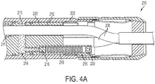
- FIG. 4A depicts a cross-sectional view of a power cable assembly 210 having multiple conductors 206 (three, for example), according to an exemplary embodiment of the invention. Many of the details of the power cable assembly 10 also apply to the power cable assembly 210, and the primary differences between those power cable assemblies will be described hereinafter.
- the cable assembly 210 includes a connector body 202 defining an interior space 213.
- the connector body 202 may also be referred to herein as a sleeve, conduit, tube or shell.
- a pressure balanced chamber 216 (referred to hereinafter as chamber 216) is defined within the interior space 213.
- the chamber 216 has a substantial cylindrical shape, and also partially extends within the proximal end of the shuttle tube assemblies 215, as best shown in FIG. 4A .
- the chamber 216 is defined at a location between the connection point 211 and the shuttle tube and cable holder 220.
- the proximal face 220a of the shuttle tube and cable holder 220 forms the distal boundary wall of the chamber 216.
- the chamber 216 is filled with a dielectric fluid medium.
- the dielectric fluid medium may be gas impermeable. Air bubbles are depicted in the chamber 216 in FIG. 4A .
- FIG. 4B depicts the shuttle tube and cable holder 220 (referred to hereinafter as holder 220) of the power cable assembly 210.
- the holder 220 of the power cable assembly 210 is positioned within the interior space of the connector body 202.
- the holder 220 comprises a cylindrical body having a proximal face 220a, a distal face 220b, and a revolved outer surface extending between the faces.
- a series of openings 212 (three, for example) are defined through the body of the holder 220 to accommodate respective conductors 206.
- the openings 212 are spaced in a radial direction from the longitudinal axis of the holder 220 and are spaced in a circumferential direction about the holder 220 (e.g., by 120 degrees). The spacing may be even in the radial and circumferential directions.
- the cable assembly 210 may include any number of conductors 206 and corresponding openings 212.
- a single electrical conductor 206 is positioned in each opening 212.
- an O-ring may be positioned on the circumference of each conductor 206 to prevent the passage of fluid at the interface between the exterior revolved surface of the conductor 206 and the interior revolved surface of the opening 212 through which the conductor 206 is positioned.
- the openings 219 are separate from and disconnected from the openings 212.
- the openings 212 and 219 are alternately positioned in a circumferential direction about the holder 220, such that each opening 219 is positioned between adjacent openings 212, and vice versa.
- An O-ring 203 is positioned on the circumference of the holder 220 to prevent the passage of fluid at the interface between the exterior revolved surface of the holder 220 and the interior revolved surface of the connector body 202.
- each shuttle tube assembly 215 generally includes a tube 217 mounted within an opening 219 defined in the holder 220, a moveable shuttle 218 positioned within the interior of the tube 217 that is biased by a spring 221, and a plug 230 that is fixedly mounted to the distal end of the tube 217.
- the hollow tube 217 of each shuttle tube assembly 215 is fixedly mounted within the opening 219 of the holder 220.
- the distal end of the hollow tube 217 protrudes from the distal end 220b of the holder 220.
- the hollow tube 217 includes a shoulder 225 that bears on an interior shoulder of the opening 219 of the holder 220.
- the shoulder 225 marks the separation between the proximal interior region 223a and the distal interior region 223b of the tube 217.
- the proximal interior region 223a forms part of the chamber 216 that contains the dielectric medium.
- the movable shuttle 218 of each shuttle tube assembly 215 comprises a cylindrical shaped solid body.
- the shuttle 218 is positioned within the distal interior region 223b of the hollow tube 217.
- An O-ring is positioned on the circumference of the movable shuttle 218 to prevent the passage of fluid at the interface between the exterior revolved surface of the shuttle 218 and the interior revolved surface of the tube 217.
- a spring 221 biases the shuttle 218 toward the chamber 216.
- the shuttle 218 is capable of translating within the distal interior region 223b of the hollow tube 217 between the shoulder 225 and the plug 230.
- each shuttle tube assembly 215 is fixedly mounted to the distal end of the tube 217.
- a passage 232 is defined through the plug 230 to permit the passage of fluid within the tube 217, such that the distal end face of the shuttle 218 is exposed to fluids or gasses within either the well environment or atmosphere, for example.
- the proximal end face of the shuttle 218 is exposed to the dielectric medium that is contained within the portion of the chamber 216 that extends into the proximal interior region 223a of the tube 217.
- the proximal end face of the shuttle 218 at least partially delimits, i.e., forms the boundary of, the chamber 216.
- the proximal end face of the shuttle 218 is exposed to the dielectric medium, whereas the distal end face of the shuttle 218 is not exposed to the dielectric medium.
- the distal end face of the shuttle 218 may be exposed to either the well environment or atmosphere, for example.
- the shuttle 218 In operation, when the dielectric medium within the pressure balanced chamber 216 expands or contracts due to temperature and/or pressure, the shuttle 218 translates within the tube 217 in response to differences between a pressure within the chamber 216 and a pressure within the distal interior region 223b of the tube 217. Translation of the shuttle 218 is limited between the shoulder 225 and the plug 218.
- the dielectric medium provides a dielectric barrier, which may be gas impermeable, that shields elastomers (not shown) that are located proximal of the chamber 216 and creates the dielectric isolation of the connector system.
- the shuttles 218 of the power cable assembly 210 are not moveably positioned over the conductors 206, or any other component, of the cable assembly 210. Separating the shuttles 218 from the other components of the cable assembly 210 eliminates the possibility that the shuttle 218 could bind on another component.
- FIG. 5 depicts a cross-sectional view of a power cable assembly. Many of the details of the power cable assembly 10 apply to the power cable assembly, and the primary differences between those power cable assemblies will be described hereinafter.
- the power cable assembly has a substantially symmetrical design and generally includes a single-conductor power cable 303 that is connected to another single-conductor power cable 304 by a double-ended socket 305.
- the double-ended socket 305 transfers power and/or signals between the power cables 303 and 304 at the power connection point 311.
- Each power cable 303 and 304 includes a copper conductor 306, a pin 307 that is fixedly mounted to the proximal end of the conductor 306, an insulative shield 324 that surrounds the copper conductor 306, and a lead barrier 326 that is positioned over the insulative shield 324.
- the lead barrier 326 protects the insulative shield 324 from exposure to harmful gasses and liquids that surround the power cable 303 in use.
- the lead barrier 326 is an optional component of the power cables 303 and 304 and may be omitted.
- the power cable assembly also includes a tube 328 that surrounds each lead barrier 326.
- the tube 328 may be composed of stainless steel, for example.
- An attached flange 330 is positioned over the proximal end of each tube 328.
- the attached flange 330 is also sandwiched between a distal end of a sleeve 315 and an internal shoulder formed on a connector shell 312a.
- the tubes 328 and the attached flange 330 may or may not be considered as forming part of the respective power cables 303 and 304. Alternatively, those components may be considered as separable parts that form part of the power cable assembly.
- the double-ended socket 305 is positioned within a dielectric insulative sleeve 313.
- the dielectric insulative sleeve 313 has a hollow cylindrical body. One end of the dielectric insulative sleeve 313 is captivated by the flange 330 of the power cable 304, and the opposite end of the sleeve 313 partially surrounds and overlaps another dielectric insulative sleeve 315.
- the sleeve 315 also has a hollow cylindrical body. The sleeve 315 is captivated by the attached flange 330 of the power cable 303.
- the dielectric insulative sleeves 313 and 315 may be composed of any dielectric insulative material.
- the dielectric insulative sleeve 313 is positioned within a male to male connector 340.
- the connector 340 has a hollow cylindrical body including male threads that are defined at opposite ends thereof.
- the connector shell 312a that is associated with the power cable 303 includes female threads at its proximal end that are threadedly connected to one threaded end of the connector 340.
- the connector shell 312b associated with the power cable 304 includes female threads at its proximal end that are threadedly connected to the opposite threaded end of the connector 340.
- the power cable assembly includes two pressure balanced chambers 314 that are each delimited by a moveable shuttle 318. Although only the chamber 314 and the shuttle 318 that are associated with the power cable 303 will be described hereinafter, it should be understood that the chamber 314 and the shuttle 318 that are associated with the power cable 304 are structurally and functionally equivalent to their counterparts associated with the power cable 303.
- annular space 301 is formed between the revolved surfaces of the connector shell 312a and the tube 328.
- a tubular-shaped shuttle 318 is positioned within the annular space 301, and is sealingly compressed between an inner surface of the connector shell 312a and outer surface of the tube 328.
- the tube 328 provides a smooth surface upon which the shuttle 318 can translate.
- the shuttle 318 divides the annular space 301 between the pressure balanced chamber 314 and an annular space 319.
- the chamber 314 is filled with a dielectric fluid medium, which is depicted by bubbles in FIG. 5 . No fluid is contained within the annular space 319.
- the shuttle 318 prevents the passage of fluid between the space 319 and the chamber 314.
- the shuttle 318 associated with the power cable 303 moves rightward when it is exposed to external pressure as any air pockets or compressible elements within the dielectric fluid will contract in volume.
- the power cable assembly is shown exposed to external pressure in FIG. 5 .
- the shuttle 318 associated with the power cable 303 may return to its initial position once the external pressure subsides. It should be understood that the other shuttle 318 moves leftward when it is exposed to external pressure, and moves rightward to return to its initial position once the external pressure subsides.
- the dual pressure balanced chamber design provides redundancy if one of the shuttles 318 were to fail or become bound in place.
- the remaining shuttle 318 and pressure balanced chamber 314 would assume the pressure balancing functionality of the power cable assembly.
- the pressure balanced chambers 314 respond to rapid decompression and pressure impulses caused by the activation and deactivation of an electrical submersible pump to which the power cable assembly may be connected.
- the dielectric fluid chambers 314 either limit or prevent well fluid that has penetrated the lead barrier 326 (or other lead barrier outside of the power cable assembly) from penetrating the power connection point 311 (or another critical point) and causing a high voltage short to ground.
- the power cable assembly is particularly suitable for well temperatures above 60 degrees Celsius (500 degrees Fahrenheit) Because such high temperatures rapidly degrade elastomeric materials, the power cable assembly employs a minimal amount of elastomers as compared with the other cable embodiments that are described herein.
Landscapes
- Connector Housings Or Holding Contact Members (AREA)
- Connections By Means Of Piercing Elements, Nuts, Or Screws (AREA)
Description
- This invention generally relates to a pressure-balanced electrical connector having a chamber filled with dielectric fluid.
- In providing electrical power to different types of wells, the connector systems will be exposed to rapidly varying pressures, temperatures and deleterious gases, each of which can cause internal sealing arrangements in a power cable or a power connector to fail.
- Power cables, which may be used for electric submersible pumps (ESP) in oil wells, are typically constructed with a copper conductor, an insulator that surrounds the copper conductor, and a lead sheath that surrounds the insulator. Lead-sheathed power cables are known and disclosed in, for example,
U.S. Patent Nos. 4,780,574 to Neuroth and5,760,334 to Ziemek . The lead material of the lead sheath protects the insulator of the power cable from damage resulting from the deleterious gases of the harsh oil well environment. The lead material of the lead sheath may also protect rubber sealing elements that are used to terminate these power cables. The rubber sealing elements are particularly vulnerable to explosive decompression and other types of damage caused by the gases. - Lead is commonly used because it is substantially impermeable to gas and moisture, inexpensive, flexible, ductile and easily removable. However, many of these qualities also make the lead sheath susceptible to damage upon changes in pressure and temperature if attempts are made to rigidly attach the lead sheath to a metal shell of a connector.
- The invention described herein maintains the gas permeation protection provided by the lead material while offering a robust solution that can better withstand mechanical handling as well as changes in pressure and temperature.
-
US patent application No. 2003/228783 A1 relates to a pressure-balanced electrical cable assembly using pressure compensator units according to the preamble of claim 1. - The above-described gas permeation protection is provided by a pressure balanced chamber of dielectric fluid, such as grease, oil or silicone, surrounding the connector termination.
- According to the invention, a pressure-balanced electrical cable assembly includes: a connector body; an electrical conductor positioned within the connector body; an interior chamber defined within and at least in part by the connector body; a dielectric fluid medium contained within the chamber; a holder positioned within the connector body, the holder at least partially defining a boundary of the chamber, the holder including a first opening through which the electrical conductor is positioned and the holder further including a second opening; and a shuttle positioned in the second opening of the holder and delimiting at least a portion of the chamber to prevent the escapement of the dielectric fluid from the chamber. The shuttle is moveable in response to differences between a pressure within the chamber and a pressure outside of the chamber.
- Other aspects of the present invention will become clear from the detailed discussion below when taken into consideration with the drawings. It is to be understood that the following discussion is intended merely to illustrate the preferred embodiment of the present invention. However, the present invention is not limited to the illustrated embodiment, but is limited solely by the claims appended to this specification.
- The invention is best understood from the following detailed description when read in connection with the accompanying drawings. It is emphasized that, according to common practice, the various features of the drawing are not to scale. Included in the drawing are the following figures:
-
FIG. 1A depicts a cross-sectional view of a power cable assembly. -
FIG. 1B depicts the power cable assembly ofFIG. 1A exposed to external pressure. -
FIG. 2 depicts a detailed view of the power cable assembly ofFIG. 1B showing a connection between components of the power cable assembly. -
FIG. 3A depicts a cross-sectional view of another power cable assembly. -
FIG. 3B depicts the power cable assembly ofFIG. 3A exposed to external pressure. -
FIG. 4A depicts a cross-sectional view of another power cable assembly, according to an exemplary embodiment of the invention. -
FIG. 4B depicts a shuttle tube and cable holder of the power cable assembly ofFIG. 4A . -
FIG. 5 depicts a cross-sectional view of another power cable assembly. - The invention will next be illustrated with reference to the figures. Such figures are intended to be illustrative rather than limiting and are included herewith to facilitate explanation of the present invention. In the figures, like item numbers refer to like elements throughout. Also, in the figures, many of the components of the power cable assembly are shown in cross-section and have a cylindrical shape.
- As used herein, the term 'proximal' refers to a position that is near a
connection point connection point -
FIGS. 1A and 1B depict a cross-sectional view of a power cable assembly. InFIG. 1B , thepower cable assembly 10 ofFIG. 1A is shown exposed to external fluid pressure. Thepower cable assembly 10 generally includes apower cable sub-assembly 2 that is configured to be connected to a power cable 4 by asleeve assembly 40. - The
power cable sub-assembly 2 comprises several interconnected components including apower cable 3 that is electrically and mechanically connected to asocket 5, and anouter sleeve 9 that surrounds thesocket 5 and the terminal end of thepower cable 3. Thepower cable sub-assembly 2 is configured to be connected to the power cable 4. More particularly, thesocket 5 of thepower cable sub-assembly 2 is configured to receive the terminal end 7 of thecopper conductor 6 of the power cable 4. Power and/or signals can be transferred between thepower cable sub-assembly 2 and the power cable 4 at apower connection point 11 that is defined at the intersection of thesocket 5 and the terminal end 7 of thecopper conductor 6. - The power cable 4 includes the
copper conductor 6, an EPDMinsulative shield 24 that surrounds thecopper conductor 6, and alead barrier 26 that is molded over the EPDMinsulative shield 24. Thelead barrier 26 protects the EPDMinsulative shield 24 from exposure to harmful gasses and liquids that surround thepower cable 10 in use. Thelead barrier 26 is an optional component of the power cable 4 and may be omitted. - The power cable 4 also includes a
stainless steel tube 28 that surrounds thelead barrier 26, arubber boot seal 30 that is positioned over the ends of the EPDMinsulative shield 24 and thelead barrier 26, and a compression ring 32 that is positioned over theboot seal 30. Thetube 28, therubber boot seal 30 and the compression ring 32 may or may not be considered as forming part of the power cable 4. Alternatively, those components may be considered as separable parts that form part of either thesleeve assembly 40 or part of thecable assembly 10. - The
tube 28 provides a smooth surface upon which ashuttle 18 can translate, as will be described in greater-detail later. The interior surface of thetube 28 may be adhered to the outer surface of thelead barrier 26 by a metal filled epoxy. One end of thetube 28 is positioned within achamber 14 and is spaced apart from theboot seal 30. The opposite end of thetube 28 extends outside of thechamber 14. - The
rubber boot seal 30, which is susceptible to damage upon contact with deleterious gases emanating outside of thechamber 14, is protected by dielectric fluid that is contained within thechamber 14. Theboot seal 30 may be adhered to the exterior surface of either one or both of theinsulative shield 24 and thelead barrier 26 by a metal filled epoxy. - The
boot seal 30 is positioned on the power cable 4 such that its proximal end face 30' is positioned flush with the proximal end face of theinsulative shield 24. Theboot seal 30 also includes an exterior shoulder upon which a flange 32' of the compression ring 32 is seated. The flange 32' of the compression ring 32 is sandwiched between theboot seal 30 and aflange 41 of theouter sleeve 12. - Referring now to the features of the
sleeve assembly 40, thesleeve assembly 40 is configured to releasably connect thepower cable sub-assembly 2 to the power cable 4. For that reason, thesleeve assembly 40 may also be referred to herein as a 'connector.' Thesleeve assembly 40 also prevents theboot seal 30 from exposure to harmful gases and liquids that surround thepower cable 10 in use. - The
sleeve assembly 40 generally includes a tubular-shapedouter sleeve 12, which is optionally composed of stainless steel, and a tubular-shapedshuttle 18, which is optionally composed of an elastomeric material, such as rubber. The outer surface of theshuttle 18 is sealingly positioned against aninner surface 20 of theouter sleeve 12, and the inner surface of theshuttle 18 is sealingly positioned against an outer surface of thetube 28. Aflange 43 is disposed at the distal end of the interior surface of theouter sleeve 12 to prevent detachment of theshuttle 18 from theouter sleeve 12. Theshuttle 18 includes a hole through which thestainless steel tube 28 of the power cable 4 passes. - An
annular chamber 14 is defined between theinterior surface 20 of theouter sleeve 12 and at least a portion of the exterior surfaces of thetube 28, theboot seal 30 and thelead barrier 26. Theannular chamber 14 is filled with dielectric silicone grease or other dielectric fluid, as depicted by bubbles, by an operator. One or more surfaces of theboot seal 30,lead barrier 26, compression ring 32,insulative shield 24,shuttle 18 are at least partially immersed in the dielectric fluid. The dielectric fluid prevents the ingress of harmful liquids and gases into thechamber 14. - The
chamber 14 is delimited by theshuttle 18. In operation, as shown inFIG. 1B , theshuttle 18 moves leftward when it is exposed to external pressure as any air pockets or compressible elements within the dielectric fluid will contract in volume (note difference in bubble size betweenFIGS. 1A and 1B ). Theshuttle 18 may return to its initial position once the external pressure subsides. This is referred to as a "pressure balanced" chamber. - At the proximal end of the
sleeve assembly 40, theboot seal 30 and the compression ring 32 prevent escapement of the grease from thechamber 14. At the distal end of thesleeve assembly 40, the O-ring shuttle 18 seals against the surfaces of thesleeve 12 and thetube 28 to prevent escapement of the grease from thechamber 14. - The
shuttle 18 includes a hole through which thestainless steel tube 28 of the power cable 4 passes. The outer surface of theshuttle 18 is positioned against theinner surface 20 of theouter sleeve 12. An elastomeric O-ring 31 is mounted in a channel that is formed on the interior surface of theshuttle 18. The O-ring 31 is positioned to bear on the exterior surface of thetube 28 to prevent the escapement of fluid at the interface between the interior surface of theshuttle 18 and the exterior surface of thetube 28. Another elastomeric O-ring 33 is mounted in a channel that is formed on the exterior surface of theshuttle 18. The O-ring 33 is positioned to bear on the interior surface of theouter sleeve 12 to prevent the escapement of fluid at the interface between the exterior surface of theshuttle 18 and the interior surface of theouter sleeve 12. Alternatively, the O-rings - Mechanical threads 42 are provided on the interior surface of the proximal end of the
outer sleeve 12 for connecting thesleeve assembly 40 with mating threads on thepower cable sub-assembly 2. Specifically, the mechanical threads 42 are configured for releasably engaging mating threads on the exterior surface of themating sleeve 9 of thepower cable sub-assembly 2. Item 42 may represent any connection means, such as a fastener, pin, slot, plug, socket, retainer, lock, adhesive, bolt, nut, engaging surface, engageable surface, magnet, or joint, for example. -
FIG. 2 depicts an O-ring 44 that is positioned at the interface between the terminal end of theouter sleeve 12 and achannel 46 that is defined at the proximal end of themating sleeve 9 of thepower cable sub-assembly 2. The O-ring 44 prevents the escapement of fluid at the interface between thesleeves ring 44 may be replaced by a metallic C-ring, if so desired. - Referring back to
FIGS. 1A, 1B and 2 , and according to one exemplary method of assembling thepower cable assembly 10, theshuttle 18 is positioned inside theouter sleeve 12. Thetube 28 is mounted to the power cable 4. Thetube 28 and the power cable 4 are then positioned through the hole in theshuttle 18. Therubber boot seal 30 and the compression ring 32 are mounted to the power cable 4. Before mating thesleeves chamber 14. The threads 42 of theouter sleeve 12 of thesleeve assembly 40 are then engaged with the mating threads of themating sleeve 9 of thepower cable sub-assembly 2. Upon engaging those mechanical threads, ashoulder 41 of theouter sleeve 12 bears against the distal end of the compression ring 32, which bears against theboot seal 30, thereby compressing the proximal end face of theboot seal 30 against the proximal end face of thesocket 5 of thepower cable sub-assembly 2. - At the same time, the terminal end 7 of the
copper conductor 6 of the power cable 4 seats in the recess of thesocket 5 of thepower cable sub-assembly 2, thereby creating a power connection between thepower cable sub-assembly 2 and the power cable 4. Also, at the same time, the proximal ends of both theboot seal 30 and theinsulative shield 24 bear against (but are disconnected from) the terminal end of thesocket 5 of thepower cable sub-assembly 2. Thepower cable assembly 10 is ready for use, and thepower cable assembly 10 may be immersed in an oil well, or other environment. - The
sleeve assembly 40 may be sold and distributed along with the power cable 4. That assembly may be supplied with or without a supply of dielectric fluid. - The
sleeve assembly 40 may also be sold and distributed as a kit for retrofitting an existing power cable assembly. The kit would include, at a minimum, theouter sleeve 12 and theshuttle 18. The kit may also include thetube 28, therubber boot seal 30, the compression ring 32 and/or a supply of dielectric fluid. - It should be understood that the materials recited herein may vary, the methods by which components are formed may vary, and the ways by which the components are connected together may vary.
-
FIG. 3A depicts a cross-sectional view of anotherpower cable assembly 110 havingmultiple conductors 106.FIG. 3B depicts thepower cable assembly 110 ofFIG. 3A exposed to external pressure. Many of the details of thepower cable assembly 10 also apply to thepower cable assembly 110, and only the differences between those power cable assemblies will be described hereinafter. - The
power cable assembly 110 generally includes apower cable sub-assembly 104 that is configured to be connected to an insulator 102 (or a mating power cable) by asleeve assembly 140. Thepower cable 104 includes a plurality of discrete conductors 106 (three shown). Thepower cable 104 also includes atube 128 that surrounds theconductors 106. - The
tube 128 provides a smooth surface upon which afirst shuttle 118a can translate, as will be described in greater detail later. The interior surface of thetube 128 may be adhered to theconductors 106 by a metal filled epoxy, for example. One end of thetube 128 is positioned within achamber 114a, and the opposite end of thetube 128 extends outside of thechamber 114a. - Referring now to the features of the
sleeve assembly 140, thesleeve assembly 140 is configured to releasably connect thepower cable 104 to theinsulator 102. For that reason, thesleeve assembly 140 may also be referred to herein as a 'connector.' Thesleeve assembly 140 also shields theconductors 106 from exposure to harmful gases and liquids that surround thepower cable assembly 110 in use. - The
sleeve assembly 140 generally includes a two-piece tubular-shapedouter sleeve shuttles shuttles inner surface 120 of the outer sleeve 112.Angled surface 145 of theouter sleeve 112a prevents detachment of theshuttle 118a from the outer sleeve 112.Stops outer sleeve 112b to prevent detachment of theshuttle 118b from the outer sleeve 112. - Unlike the
sleeve assembly 40, thesleeve assembly 140 includes two fluid filledchambers shuttles - The
shuttle 118a includes a hole through which thetube 128 of thepower cable 104 passes. Theshuttle 118a slides along the surface of thetube 128 in response to pressures emanating external to thepower cable assembly 110, as evidenced by comparingFIGS. 3A and 3B . - The
other shuttle 118b includes several holes, and agrommet 147 that is fixedly positioned in each hole. The number of holes and grommets corresponds to the number ofconductors 106. Eachconductor 106 of thecable 104 passes through an opening in one of thegrommets 147, as shown. Thegrommets 147 of theshuttle 118b slide along the surface of theindividual conductors 106 in response to pressures emanating external to thepower cable assembly 110, as evidenced by comparingFIGS. 3A and 3B . Thus, thegrommets 147 translate along with theshuttle 118b in response to external pressure. - One
chamber 114a is defined between theshuttles other chamber 114b is defined between theshuttle 118b and theinsulator 102. Theannular chambers conductors 106 are at least partially immersed in the dielectric fluid. The dielectric fluid prevents the ingress of harmful liquids and gases into thechambers - In operation, as shown in
FIGS. 3B , theshuttles shuttle 118a is exposed to external pressure as any air pockets or compressible elements within the dielectric fluid will contract in volume (note difference in bubble size betweenFIGS. 3A and 3B ). Theshuttles FIG. 3A once the external pressure subsides. This is referred to as a "pressure balanced" chamber. - As noted above, two shuttles 118 and two chambers 114 are provided for the purpose of redundancy. In the event that the
first shuttle 118a fails, thereby resulting in contamination of thechamber 114a, a second failure would have to occur for the contamination to reach theother chamber 114b. - As an alternative to the arrangement shown in
FIGS. 3A and 3B , thegrommets 147 are fixed to theconductors 106 such thatgrommets 147 and theshuttle 118b can not translate over theconductors 106; and a moveable seal (not shown) is positioned over theseal 118b. The moveable seal would translate over theseal 118b in response to external pressure. -
FIG. 4A depicts a cross-sectional view of apower cable assembly 210 having multiple conductors 206 (three, for example), according to an exemplary embodiment of the invention. Many of the details of thepower cable assembly 10 also apply to thepower cable assembly 210, and the primary differences between those power cable assemblies will be described hereinafter. - The
cable assembly 210 includes aconnector body 202 defining aninterior space 213. Theconnector body 202 may also be referred to herein as a sleeve, conduit, tube or shell. A pressure balanced chamber 216 (referred to hereinafter as chamber 216) is defined within theinterior space 213. Thechamber 216 has a substantial cylindrical shape, and also partially extends within the proximal end of theshuttle tube assemblies 215, as best shown inFIG. 4A . Thechamber 216 is defined at a location between theconnection point 211 and the shuttle tube andcable holder 220. Theproximal face 220a of the shuttle tube andcable holder 220 forms the distal boundary wall of thechamber 216. Thechamber 216 is filled with a dielectric fluid medium. The dielectric fluid medium may be gas impermeable. Air bubbles are depicted in thechamber 216 inFIG. 4A . -
FIG. 4B depicts the shuttle tube and cable holder 220 (referred to hereinafter as holder 220) of thepower cable assembly 210. Theholder 220 of thepower cable assembly 210 is positioned within the interior space of theconnector body 202. Theholder 220 comprises a cylindrical body having aproximal face 220a, adistal face 220b, and a revolved outer surface extending between the faces. A series of openings 212 (three, for example) are defined through the body of theholder 220 to accommodaterespective conductors 206. Theopenings 212 are spaced in a radial direction from the longitudinal axis of theholder 220 and are spaced in a circumferential direction about the holder 220 (e.g., by 120 degrees). The spacing may be even in the radial and circumferential directions. Thecable assembly 210 may include any number ofconductors 206 andcorresponding openings 212. - A single
electrical conductor 206 is positioned in eachopening 212. Although not shown, an O-ring may be positioned on the circumference of eachconductor 206 to prevent the passage of fluid at the interface between the exterior revolved surface of theconductor 206 and the interior revolved surface of theopening 212 through which theconductor 206 is positioned. - A series of counter-bored openings 219 (three, for example) are defined through the body of the
holder 220 to accommodate respectiveshuttle tube assemblies 215. Theopenings 219 are spaced in a radial direction from the longitudinal axis of theholder 220, and are spaced in a circumferential direction about the holder 220 (e.g., by 120 degrees). The spacing may be even in the radial and circumferential directions. - The
openings 219 are separate from and disconnected from theopenings 212. Theopenings holder 220, such that eachopening 219 is positioned betweenadjacent openings 212, and vice versa. - An O-
ring 203 is positioned on the circumference of theholder 220 to prevent the passage of fluid at the interface between the exterior revolved surface of theholder 220 and the interior revolved surface of theconnector body 202. - Turning now to the features of the
shuttle tube assemblies 215, eachshuttle tube assembly 215 generally includes atube 217 mounted within anopening 219 defined in theholder 220, amoveable shuttle 218 positioned within the interior of thetube 217 that is biased by aspring 221, and aplug 230 that is fixedly mounted to the distal end of thetube 217. - The
hollow tube 217 of eachshuttle tube assembly 215 is fixedly mounted within theopening 219 of theholder 220. The distal end of thehollow tube 217 protrudes from thedistal end 220b of theholder 220. Thehollow tube 217 includes ashoulder 225 that bears on an interior shoulder of theopening 219 of theholder 220. Theshoulder 225 marks the separation between the proximalinterior region 223a and the distalinterior region 223b of thetube 217. The proximalinterior region 223a forms part of thechamber 216 that contains the dielectric medium. - The
movable shuttle 218 of eachshuttle tube assembly 215 comprises a cylindrical shaped solid body. Theshuttle 218 is positioned within the distalinterior region 223b of thehollow tube 217. An O-ring is positioned on the circumference of themovable shuttle 218 to prevent the passage of fluid at the interface between the exterior revolved surface of theshuttle 218 and the interior revolved surface of thetube 217. Aspring 221 biases theshuttle 218 toward thechamber 216. Theshuttle 218 is capable of translating within the distalinterior region 223b of thehollow tube 217 between theshoulder 225 and theplug 230. - The
plug 230 of eachshuttle tube assembly 215 is fixedly mounted to the distal end of thetube 217. Apassage 232 is defined through theplug 230 to permit the passage of fluid within thetube 217, such that the distal end face of theshuttle 218 is exposed to fluids or gasses within either the well environment or atmosphere, for example. - The proximal end face of the
shuttle 218 is exposed to the dielectric medium that is contained within the portion of thechamber 216 that extends into the proximalinterior region 223a of thetube 217. The proximal end face of theshuttle 218 at least partially delimits, i.e., forms the boundary of, thechamber 216. Thus, the proximal end face of theshuttle 218 is exposed to the dielectric medium, whereas the distal end face of theshuttle 218 is not exposed to the dielectric medium. The distal end face of theshuttle 218 may be exposed to either the well environment or atmosphere, for example. - In operation, when the dielectric medium within the pressure
balanced chamber 216 expands or contracts due to temperature and/or pressure, theshuttle 218 translates within thetube 217 in response to differences between a pressure within thechamber 216 and a pressure within the distalinterior region 223b of thetube 217. Translation of theshuttle 218 is limited between theshoulder 225 and theplug 218. The dielectric medium provides a dielectric barrier, which may be gas impermeable, that shields elastomers (not shown) that are located proximal of thechamber 216 and creates the dielectric isolation of the connector system. - Unlike the
shuttle 18 of thepower cable assembly 10, theshuttles 218 of thepower cable assembly 210 are not moveably positioned over theconductors 206, or any other component, of thecable assembly 210. Separating theshuttles 218 from the other components of thecable assembly 210 eliminates the possibility that theshuttle 218 could bind on another component. -
FIG. 5 depicts a cross-sectional view of a power cable assembly. Many of the details of thepower cable assembly 10 apply to the power cable assembly, and the primary differences between those power cable assemblies will be described hereinafter. - The power cable assembly has a substantially symmetrical design and generally includes a single-
conductor power cable 303 that is connected to another single-conductor power cable 304 by a double-endedsocket 305. The double-endedsocket 305 transfers power and/or signals between thepower cables power connection point 311. - Each
power cable copper conductor 306, apin 307 that is fixedly mounted to the proximal end of theconductor 306, aninsulative shield 324 that surrounds thecopper conductor 306, and alead barrier 326 that is positioned over theinsulative shield 324. Thelead barrier 326 protects theinsulative shield 324 from exposure to harmful gasses and liquids that surround thepower cable 303 in use. Thelead barrier 326 is an optional component of thepower cables - The power cable assembly also includes a
tube 328 that surrounds eachlead barrier 326. Thetube 328 may be composed of stainless steel, for example. An attachedflange 330 is positioned over the proximal end of eachtube 328. The attachedflange 330 is also sandwiched between a distal end of asleeve 315 and an internal shoulder formed on aconnector shell 312a. Thetubes 328 and the attachedflange 330 may or may not be considered as forming part of therespective power cables socket 305 is positioned within a dielectricinsulative sleeve 313. The dielectricinsulative sleeve 313 has a hollow cylindrical body. One end of the dielectricinsulative sleeve 313 is captivated by theflange 330 of thepower cable 304, and the opposite end of thesleeve 313 partially surrounds and overlaps another dielectricinsulative sleeve 315. Thesleeve 315 also has a hollow cylindrical body. Thesleeve 315 is captivated by the attachedflange 330 of thepower cable 303. The dielectricinsulative sleeves - The dielectric
insulative sleeve 313 is positioned within a male tomale connector 340. Theconnector 340 has a hollow cylindrical body including male threads that are defined at opposite ends thereof. Theconnector shell 312a that is associated with thepower cable 303 includes female threads at its proximal end that are threadedly connected to one threaded end of theconnector 340. Similarly, theconnector shell 312b associated with thepower cable 304 includes female threads at its proximal end that are threadedly connected to the opposite threaded end of theconnector 340. - The power cable assembly includes two pressure
balanced chambers 314 that are each delimited by amoveable shuttle 318. Although only thechamber 314 and theshuttle 318 that are associated with thepower cable 303 will be described hereinafter, it should be understood that thechamber 314 and theshuttle 318 that are associated with thepower cable 304 are structurally and functionally equivalent to their counterparts associated with thepower cable 303. - Referring now to the pressure
balanced chamber 314 associated with thepower cable 303, anannular space 301 is formed between the revolved surfaces of theconnector shell 312a and thetube 328. A tubular-shapedshuttle 318 is positioned within theannular space 301, and is sealingly compressed between an inner surface of theconnector shell 312a and outer surface of thetube 328. Thetube 328 provides a smooth surface upon which theshuttle 318 can translate. - The
shuttle 318 divides theannular space 301 between the pressurebalanced chamber 314 and anannular space 319. Thechamber 314 is filled with a dielectric fluid medium, which is depicted by bubbles inFIG. 5 . No fluid is contained within theannular space 319. Theshuttle 318 prevents the passage of fluid between thespace 319 and thechamber 314. - In operation, the
shuttle 318 associated with thepower cable 303 moves rightward when it is exposed to external pressure as any air pockets or compressible elements within the dielectric fluid will contract in volume. The power cable assembly is shown exposed to external pressure inFIG. 5 . Theshuttle 318 associated with thepower cable 303 may return to its initial position once the external pressure subsides. It should be understood that theother shuttle 318 moves leftward when it is exposed to external pressure, and moves rightward to return to its initial position once the external pressure subsides. The dual pressure balanced chamber design provides redundancy if one of theshuttles 318 were to fail or become bound in place. The remainingshuttle 318 and pressurebalanced chamber 314 would assume the pressure balancing functionality of the power cable assembly. The pressurebalanced chambers 314 respond to rapid decompression and pressure impulses caused by the activation and deactivation of an electrical submersible pump to which the power cable assembly may be connected. - Testing has shown that the
dielectric fluid chambers 314 either limit or prevent well fluid that has penetrated the lead barrier 326 (or other lead barrier outside of the power cable assembly) from penetrating the power connection point 311 (or another critical point) and causing a high voltage short to ground. - Testing has also shown that the power cable assembly is particularly suitable for well temperatures above 60 degrees Celsius (500 degrees Fahrenheit) Because such high temperatures rapidly degrade elastomeric materials, the power cable assembly employs a minimal amount of elastomers as compared with the other cable embodiments that are described herein.
- Although the invention is illustrated and described herein with reference to a specific embodiment, the invention is not intended to be limited to the details shown. Rather, various modifications may be made in the details within the scope of the claims.
Claims (10)
- A pressure-balanced electrical cable assembly comprising:a connector body (202);an electrical conductor (206) positioned within the connector body (202);an interior chamber (216) defined within and at least in part by the connector body (202);a dielectric fluid medium contained within the interior chamber (216);a holder (220) positioned within the connector body (202), the holder (220) at least partially defining a boundary of the chamber (216), the holder (220) including a first opening (212) through which the electrical conductor (206) is positioned; anda shuttle (218) for preventing the escapement of the dielectric fluid medium from the chamber (216), the shuttle (218) being moveable in response to differences between a pressure within the chamber (216) and a pressure outside of the chamber (216); wherein the shuttle (218) delimits at least a portion of the chamber (216),wherein the pressure-balanced electrical cable assembly is characterised in that:
the holder (220) further includes a second opening (219) within which the shuttle (218) is positioned. - The pressure-balanced electrical cable assembly of claim 1 further comprising a spring (221) for biasing the shuttle (218) towards the chamber (216).
- The pressure-balanced electrical cable assembly of claim 1 further comprising a plug (230) that serves as a translation stop for the shuttle (218).
- The pressure-balanced electrical cable assembly of claim 3, wherein the plug (230) includes an opening (232) that exposes the shuttle (218) to the pressure outside of the chamber (216).
- The pressure-balanced electrical cable assembly of claim 1 further comprising a plurality of shuttles (218).
- The pressure-balanced electrical cable assembly of claim 5, wherein the plurality of shuttles (218) are spaced in a circumferential direction about the connector (206).
- The pressure-balanced electrical cable assembly of claim 1 further comprising a plurality of electrical conductors (206) positioned within the connector body (202).
- The pressure-balanced electrical cable assembly of claim 7, further comprising a plurality of shuttles (218), wherein the shuttles (218) and the electrical conductors (206) are alternately positioned in a circumferential direction about the cable assembly.
- The pressure-balanced electrical cable assembly of claim 1, wherein the electrical conductor is immersed in the fluid medium.
- The pressure-balanced electrical cable assembly of claim 1 further comprising:a second connector body;a second electrical conductor positioned within the second connector body, said second electrical conductor being electrically connected to said electrical conductor;a second interior chamber defined within the second connector body and dielectric fluid medium contained within the second interior chamber; anda second shuttle delimiting at least a portion of the second chamber to prevent the escapement of dielectric fluid medium from the second chamber, the shuttle being moveable in response to differences between a pressure within the second chamber and a pressure outside of the second chamber.
Applications Claiming Priority (2)
| Application Number | Priority Date | Filing Date | Title |
|---|---|---|---|
| US14/054,137 US8816197B2 (en) | 2012-10-04 | 2013-10-15 | Pressure balanced connector termination |
| PCT/US2014/060254 WO2015057563A1 (en) | 2013-10-15 | 2014-10-13 | Pressure balanced connector termination |
Publications (2)
| Publication Number | Publication Date |
|---|---|
| EP3058623A1 EP3058623A1 (en) | 2016-08-24 |
| EP3058623B1 true EP3058623B1 (en) | 2018-07-11 |
Family
ID=51842872
Family Applications (1)
| Application Number | Title | Priority Date | Filing Date |
|---|---|---|---|
| EP14790928.7A Active EP3058623B1 (en) | 2013-10-15 | 2014-10-13 | Pressure balanced connector termination |
Country Status (5)
| Country | Link |
|---|---|
| EP (1) | EP3058623B1 (en) |
| BR (1) | BR112016007149A2 (en) |
| CA (1) | CA2927097C (en) |
| WO (1) | WO2015057563A1 (en) |
| ZA (1) | ZA201601841B (en) |
Family Cites Families (7)
| Publication number | Priority date | Publication date | Assignee | Title |
|---|---|---|---|---|
| US4142770A (en) * | 1977-12-27 | 1979-03-06 | Exxon Production Research Company | Subsea electrical connector |
| US4174875A (en) * | 1978-05-30 | 1979-11-20 | The United States Of America As Represented By The Secretary Of The Navy | Coaxial wet connector with spring operated piston |
| US4780574A (en) | 1987-04-16 | 1988-10-25 | Hubbell Incorporated | Lead sheathed power cable |
| US5760334A (en) | 1996-07-24 | 1998-06-02 | Alcatel Kabel Ag & Co. | Metallic sheath for an electric cable and method of making the same |
| GB2330702A (en) * | 1997-09-09 | 1999-04-28 | Hydro Bond Engineering Limited | Electrical and/or optical connector |
| US6796821B2 (en) * | 2002-06-06 | 2004-09-28 | Ocean Design, Inc. | Field installable cable termination assembly |
| NO325860B1 (en) * | 2006-06-30 | 2008-08-04 | Vetco Gray Scandinavia As | Connector arrangement with a penetrator in a submersible electrical assembly |
-
2014
- 2014-10-13 BR BR112016007149A patent/BR112016007149A2/en not_active Application Discontinuation
- 2014-10-13 WO PCT/US2014/060254 patent/WO2015057563A1/en active Application Filing
- 2014-10-13 EP EP14790928.7A patent/EP3058623B1/en active Active
- 2014-10-13 CA CA2927097A patent/CA2927097C/en active Active
-
2016
- 2016-03-16 ZA ZA2016/01841A patent/ZA201601841B/en unknown
Non-Patent Citations (1)
| Title |
|---|
| None * |
Also Published As
| Publication number | Publication date |
|---|---|
| EP3058623A1 (en) | 2016-08-24 |
| WO2015057563A1 (en) | 2015-04-23 |
| CA2927097C (en) | 2017-05-02 |
| BR112016007149A2 (en) | 2017-08-01 |
| ZA201601841B (en) | 2017-09-27 |
| CA2927097A1 (en) | 2015-04-23 |
Similar Documents
| Publication | Publication Date | Title |
|---|---|---|
| US8816197B2 (en) | Pressure balanced connector termination | |
| EP2771539B1 (en) | Pressure balanced connector termination | |
| EP2940242B1 (en) | Pressure-blocking feedthru | |
| US9270051B1 (en) | Wet mate connector | |
| US6796821B2 (en) | Field installable cable termination assembly | |
| US8025506B2 (en) | Harsh environment rotary joint electrical connector | |
| EP2756567B1 (en) | High temperature, high pressure subsea electrical connector system | |
| US9209549B2 (en) | Downhole cable termination systems | |
| US10938145B2 (en) | Systems and methods for sealing motor lead extensions | |
| EP3166184A1 (en) | Subsea screen connection assembly | |
| EP2865054B1 (en) | Downhole cable termination apparatus and method thereof | |
| US9520706B2 (en) | Downhole cable termination systems | |
| US9780482B2 (en) | Method of dry-mating a first connector part and a second connector part and connector assembly | |
| EP3058623B1 (en) | Pressure balanced connector termination | |
| EP3152803B1 (en) | Connector part of a connector unit |
Legal Events
| Date | Code | Title | Description |
|---|---|---|---|
| PUAI | Public reference made under article 153(3) epc to a published international application that has entered the european phase |
Free format text: ORIGINAL CODE: 0009012 |
|
| 17P | Request for examination filed |
Effective date: 20160420 |
|
| AK | Designated contracting states |
Kind code of ref document: A1 Designated state(s): AL AT BE BG CH CY CZ DE DK EE ES FI FR GB GR HR HU IE IS IT LI LT LU LV MC MK MT NL NO PL PT RO RS SE SI SK SM TR |
|
| AX | Request for extension of the european patent |
Extension state: BA ME |
|
| DAX | Request for extension of the european patent (deleted) | ||
| 17Q | First examination report despatched |
Effective date: 20170331 |
|
| GRAJ | Information related to disapproval of communication of intention to grant by the applicant or resumption of examination proceedings by the epo deleted |
Free format text: ORIGINAL CODE: EPIDOSDIGR1 |
|
| GRAP | Despatch of communication of intention to grant a patent |
Free format text: ORIGINAL CODE: EPIDOSNIGR1 |
|
| GRAP | Despatch of communication of intention to grant a patent |
Free format text: ORIGINAL CODE: EPIDOSNIGR1 |
|
| INTG | Intention to grant announced |
Effective date: 20180122 |
|
| GRAS | Grant fee paid |
Free format text: ORIGINAL CODE: EPIDOSNIGR3 |
|
| GRAA | (expected) grant |
Free format text: ORIGINAL CODE: 0009210 |
|
| AK | Designated contracting states |
Kind code of ref document: B1 Designated state(s): AL AT BE BG CH CY CZ DE DK EE ES FI FR GB GR HR HU IE IS IT LI LT LU LV MC MK MT NL NO PL PT RO RS SE SI SK SM TR |
|
| REG | Reference to a national code |
Ref country code: GB Ref legal event code: FG4D |
|
| REG | Reference to a national code |
Ref country code: CH Ref legal event code: EP |
|
| REG | Reference to a national code |
Ref country code: AT Ref legal event code: REF Ref document number: 1017895 Country of ref document: AT Kind code of ref document: T Effective date: 20180715 |
|
| REG | Reference to a national code |
Ref country code: IE Ref legal event code: FG4D |
|
| REG | Reference to a national code |
Ref country code: DE Ref legal event code: R096 Ref document number: 602014028385 Country of ref document: DE |
|
| REG | Reference to a national code |
Ref country code: NL Ref legal event code: MP Effective date: 20180711 |
|
| REG | Reference to a national code |
Ref country code: LT Ref legal event code: MG4D |
|
| REG | Reference to a national code |
Ref country code: AT Ref legal event code: MK05 Ref document number: 1017895 Country of ref document: AT Kind code of ref document: T Effective date: 20180711 |
|
| PG25 | Lapsed in a contracting state [announced via postgrant information from national office to epo] |
Ref country code: NL Free format text: LAPSE BECAUSE OF FAILURE TO SUBMIT A TRANSLATION OF THE DESCRIPTION OR TO PAY THE FEE WITHIN THE PRESCRIBED TIME-LIMIT Effective date: 20180711 |
|
| PG25 | Lapsed in a contracting state [announced via postgrant information from national office to epo] |
Ref country code: GR Free format text: LAPSE BECAUSE OF FAILURE TO SUBMIT A TRANSLATION OF THE DESCRIPTION OR TO PAY THE FEE WITHIN THE PRESCRIBED TIME-LIMIT Effective date: 20181012 Ref country code: AT Free format text: LAPSE BECAUSE OF FAILURE TO SUBMIT A TRANSLATION OF THE DESCRIPTION OR TO PAY THE FEE WITHIN THE PRESCRIBED TIME-LIMIT Effective date: 20180711 Ref country code: BG Free format text: LAPSE BECAUSE OF FAILURE TO SUBMIT A TRANSLATION OF THE DESCRIPTION OR TO PAY THE FEE WITHIN THE PRESCRIBED TIME-LIMIT Effective date: 20181011 Ref country code: NO Free format text: LAPSE BECAUSE OF FAILURE TO SUBMIT A TRANSLATION OF THE DESCRIPTION OR TO PAY THE FEE WITHIN THE PRESCRIBED TIME-LIMIT Effective date: 20181011 Ref country code: IS Free format text: LAPSE BECAUSE OF FAILURE TO SUBMIT A TRANSLATION OF THE DESCRIPTION OR TO PAY THE FEE WITHIN THE PRESCRIBED TIME-LIMIT Effective date: 20181111 Ref country code: RS Free format text: LAPSE BECAUSE OF FAILURE TO SUBMIT A TRANSLATION OF THE DESCRIPTION OR TO PAY THE FEE WITHIN THE PRESCRIBED TIME-LIMIT Effective date: 20180711 Ref country code: FI Free format text: LAPSE BECAUSE OF FAILURE TO SUBMIT A TRANSLATION OF THE DESCRIPTION OR TO PAY THE FEE WITHIN THE PRESCRIBED TIME-LIMIT Effective date: 20180711 Ref country code: LT Free format text: LAPSE BECAUSE OF FAILURE TO SUBMIT A TRANSLATION OF THE DESCRIPTION OR TO PAY THE FEE WITHIN THE PRESCRIBED TIME-LIMIT Effective date: 20180711 Ref country code: SE Free format text: LAPSE BECAUSE OF FAILURE TO SUBMIT A TRANSLATION OF THE DESCRIPTION OR TO PAY THE FEE WITHIN THE PRESCRIBED TIME-LIMIT Effective date: 20180711 Ref country code: PL Free format text: LAPSE BECAUSE OF FAILURE TO SUBMIT A TRANSLATION OF THE DESCRIPTION OR TO PAY THE FEE WITHIN THE PRESCRIBED TIME-LIMIT Effective date: 20180711 |
|
| PG25 | Lapsed in a contracting state [announced via postgrant information from national office to epo] |
Ref country code: AL Free format text: LAPSE BECAUSE OF FAILURE TO SUBMIT A TRANSLATION OF THE DESCRIPTION OR TO PAY THE FEE WITHIN THE PRESCRIBED TIME-LIMIT Effective date: 20180711 Ref country code: LV Free format text: LAPSE BECAUSE OF FAILURE TO SUBMIT A TRANSLATION OF THE DESCRIPTION OR TO PAY THE FEE WITHIN THE PRESCRIBED TIME-LIMIT Effective date: 20180711 Ref country code: HR Free format text: LAPSE BECAUSE OF FAILURE TO SUBMIT A TRANSLATION OF THE DESCRIPTION OR TO PAY THE FEE WITHIN THE PRESCRIBED TIME-LIMIT Effective date: 20180711 |
|
| REG | Reference to a national code |
Ref country code: DE Ref legal event code: R097 Ref document number: 602014028385 Country of ref document: DE |
|
| PG25 | Lapsed in a contracting state [announced via postgrant information from national office to epo] |
Ref country code: EE Free format text: LAPSE BECAUSE OF FAILURE TO SUBMIT A TRANSLATION OF THE DESCRIPTION OR TO PAY THE FEE WITHIN THE PRESCRIBED TIME-LIMIT Effective date: 20180711 Ref country code: CZ Free format text: LAPSE BECAUSE OF FAILURE TO SUBMIT A TRANSLATION OF THE DESCRIPTION OR TO PAY THE FEE WITHIN THE PRESCRIBED TIME-LIMIT Effective date: 20180711 Ref country code: ES Free format text: LAPSE BECAUSE OF FAILURE TO SUBMIT A TRANSLATION OF THE DESCRIPTION OR TO PAY THE FEE WITHIN THE PRESCRIBED TIME-LIMIT Effective date: 20180711 Ref country code: IT Free format text: LAPSE BECAUSE OF FAILURE TO SUBMIT A TRANSLATION OF THE DESCRIPTION OR TO PAY THE FEE WITHIN THE PRESCRIBED TIME-LIMIT Effective date: 20180711 Ref country code: RO Free format text: LAPSE BECAUSE OF FAILURE TO SUBMIT A TRANSLATION OF THE DESCRIPTION OR TO PAY THE FEE WITHIN THE PRESCRIBED TIME-LIMIT Effective date: 20180711 |
|
| REG | Reference to a national code |
Ref country code: DE Ref legal event code: R119 Ref document number: 602014028385 Country of ref document: DE |
|
| PLBE | No opposition filed within time limit |
Free format text: ORIGINAL CODE: 0009261 |
|
| STAA | Information on the status of an ep patent application or granted ep patent |
Free format text: STATUS: NO OPPOSITION FILED WITHIN TIME LIMIT |
|
| PG25 | Lapsed in a contracting state [announced via postgrant information from national office to epo] |
Ref country code: SK Free format text: LAPSE BECAUSE OF FAILURE TO SUBMIT A TRANSLATION OF THE DESCRIPTION OR TO PAY THE FEE WITHIN THE PRESCRIBED TIME-LIMIT Effective date: 20180711 Ref country code: SM Free format text: LAPSE BECAUSE OF FAILURE TO SUBMIT A TRANSLATION OF THE DESCRIPTION OR TO PAY THE FEE WITHIN THE PRESCRIBED TIME-LIMIT Effective date: 20180711 Ref country code: DK Free format text: LAPSE BECAUSE OF FAILURE TO SUBMIT A TRANSLATION OF THE DESCRIPTION OR TO PAY THE FEE WITHIN THE PRESCRIBED TIME-LIMIT Effective date: 20180711 |
|
| REG | Reference to a national code |
Ref country code: CH Ref legal event code: PL |
|
| 26N | No opposition filed |
Effective date: 20190412 |
|
| REG | Reference to a national code |
Ref country code: BE Ref legal event code: MM Effective date: 20181031 |
|
| PG25 | Lapsed in a contracting state [announced via postgrant information from national office to epo] |
Ref country code: LU Free format text: LAPSE BECAUSE OF NON-PAYMENT OF DUE FEES Effective date: 20181013 Ref country code: MC Free format text: LAPSE BECAUSE OF FAILURE TO SUBMIT A TRANSLATION OF THE DESCRIPTION OR TO PAY THE FEE WITHIN THE PRESCRIBED TIME-LIMIT Effective date: 20180711 |
|
| REG | Reference to a national code |
Ref country code: IE Ref legal event code: MM4A |
|
| PG25 | Lapsed in a contracting state [announced via postgrant information from national office to epo] |
Ref country code: DE Free format text: LAPSE BECAUSE OF NON-PAYMENT OF DUE FEES Effective date: 20190501 |
|
| PG25 | Lapsed in a contracting state [announced via postgrant information from national office to epo] |
Ref country code: BE Free format text: LAPSE BECAUSE OF NON-PAYMENT OF DUE FEES Effective date: 20181031 Ref country code: FR Free format text: LAPSE BECAUSE OF NON-PAYMENT OF DUE FEES Effective date: 20181031 Ref country code: SI Free format text: LAPSE BECAUSE OF FAILURE TO SUBMIT A TRANSLATION OF THE DESCRIPTION OR TO PAY THE FEE WITHIN THE PRESCRIBED TIME-LIMIT Effective date: 20180711 Ref country code: CH Free format text: LAPSE BECAUSE OF NON-PAYMENT OF DUE FEES Effective date: 20181031 Ref country code: LI Free format text: LAPSE BECAUSE OF NON-PAYMENT OF DUE FEES Effective date: 20181031 |
|
| PG25 | Lapsed in a contracting state [announced via postgrant information from national office to epo] |
Ref country code: IE Free format text: LAPSE BECAUSE OF NON-PAYMENT OF DUE FEES Effective date: 20181013 |
|
| PG25 | Lapsed in a contracting state [announced via postgrant information from national office to epo] |
Ref country code: MT Free format text: LAPSE BECAUSE OF NON-PAYMENT OF DUE FEES Effective date: 20181013 |
|
| PG25 | Lapsed in a contracting state [announced via postgrant information from national office to epo] |
Ref country code: TR Free format text: LAPSE BECAUSE OF FAILURE TO SUBMIT A TRANSLATION OF THE DESCRIPTION OR TO PAY THE FEE WITHIN THE PRESCRIBED TIME-LIMIT Effective date: 20180711 |
|
| PG25 | Lapsed in a contracting state [announced via postgrant information from national office to epo] |
Ref country code: PT Free format text: LAPSE BECAUSE OF FAILURE TO SUBMIT A TRANSLATION OF THE DESCRIPTION OR TO PAY THE FEE WITHIN THE PRESCRIBED TIME-LIMIT Effective date: 20180711 |
|
| PG25 | Lapsed in a contracting state [announced via postgrant information from national office to epo] |
Ref country code: HU Free format text: LAPSE BECAUSE OF FAILURE TO SUBMIT A TRANSLATION OF THE DESCRIPTION OR TO PAY THE FEE WITHIN THE PRESCRIBED TIME-LIMIT; INVALID AB INITIO Effective date: 20141013 Ref country code: CY Free format text: LAPSE BECAUSE OF FAILURE TO SUBMIT A TRANSLATION OF THE DESCRIPTION OR TO PAY THE FEE WITHIN THE PRESCRIBED TIME-LIMIT Effective date: 20180711 Ref country code: MK Free format text: LAPSE BECAUSE OF NON-PAYMENT OF DUE FEES Effective date: 20180711 |
|
| P01 | Opt-out of the competence of the unified patent court (upc) registered |
Effective date: 20230528 |
|
| PGFP | Annual fee paid to national office [announced via postgrant information from national office to epo] |
Ref country code: GB Payment date: 20230920 Year of fee payment: 10 |