EP3058609B1 - Electrode plate and methods for manufacturing and testing an electrode plate - Google Patents
Electrode plate and methods for manufacturing and testing an electrode plate Download PDFInfo
- Publication number
- EP3058609B1 EP3058609B1 EP14854312.7A EP14854312A EP3058609B1 EP 3058609 B1 EP3058609 B1 EP 3058609B1 EP 14854312 A EP14854312 A EP 14854312A EP 3058609 B1 EP3058609 B1 EP 3058609B1
- Authority
- EP
- European Patent Office
- Prior art keywords
- electrode plate
- frangible portions
- adjacent
- battery
- gas
- Prior art date
- Legal status (The legal status is an assumption and is not a legal conclusion. Google has not performed a legal analysis and makes no representation as to the accuracy of the status listed.)
- Active
Links
- 238000012360 testing method Methods 0.000 title claims description 30
- 238000000034 method Methods 0.000 title claims description 17
- 238000004519 manufacturing process Methods 0.000 title claims description 11
- 239000003792 electrolyte Substances 0.000 claims description 27
- 239000007789 gas Substances 0.000 claims description 19
- 229920001903 high density polyethylene Polymers 0.000 claims description 10
- 239000004700 high-density polyethylene Substances 0.000 claims description 10
- 238000007373 indentation Methods 0.000 claims description 5
- 229920000642 polymer Polymers 0.000 claims description 5
- 239000001257 hydrogen Substances 0.000 claims description 3
- 229910052739 hydrogen Inorganic materials 0.000 claims description 3
- 238000007789 sealing Methods 0.000 claims description 3
- 238000010998 test method Methods 0.000 claims description 3
- UFHFLCQGNIYNRP-UHFFFAOYSA-N Hydrogen Chemical compound [H][H] UFHFLCQGNIYNRP-UHFFFAOYSA-N 0.000 claims description 2
- 238000010586 diagram Methods 0.000 description 22
- 239000002253 acid Substances 0.000 description 9
- 230000002950 deficient Effects 0.000 description 7
- 239000000463 material Substances 0.000 description 3
- 238000001514 detection method Methods 0.000 description 2
- 230000007613 environmental effect Effects 0.000 description 2
- 238000005086 pumping Methods 0.000 description 2
- OKTJSMMVPCPJKN-UHFFFAOYSA-N Carbon Chemical compound [C] OKTJSMMVPCPJKN-UHFFFAOYSA-N 0.000 description 1
- ZRXYMHTYEQQBLN-UHFFFAOYSA-N [Br].[Zn] Chemical compound [Br].[Zn] ZRXYMHTYEQQBLN-UHFFFAOYSA-N 0.000 description 1
- ICGLOTCMOYCOTB-UHFFFAOYSA-N [Cl].[Zn] Chemical compound [Cl].[Zn] ICGLOTCMOYCOTB-UHFFFAOYSA-N 0.000 description 1
- 230000007547 defect Effects 0.000 description 1
- 230000000694 effects Effects 0.000 description 1
- 239000000446 fuel Substances 0.000 description 1
- 229910002804 graphite Inorganic materials 0.000 description 1
- 239000010439 graphite Substances 0.000 description 1
- 231100001261 hazardous Toxicity 0.000 description 1
- 150000002431 hydrogen Chemical class 0.000 description 1
- 239000004033 plastic Substances 0.000 description 1
- 229920003023 plastic Polymers 0.000 description 1
- 239000011347 resin Substances 0.000 description 1
- 229920005989 resin Polymers 0.000 description 1
- 239000000126 substance Substances 0.000 description 1
- 229910052720 vanadium Inorganic materials 0.000 description 1
- LEONUFNNVUYDNQ-UHFFFAOYSA-N vanadium atom Chemical compound [V] LEONUFNNVUYDNQ-UHFFFAOYSA-N 0.000 description 1
Images
Classifications
-
- H—ELECTRICITY
- H01—ELECTRIC ELEMENTS
- H01M—PROCESSES OR MEANS, e.g. BATTERIES, FOR THE DIRECT CONVERSION OF CHEMICAL ENERGY INTO ELECTRICAL ENERGY
- H01M8/00—Fuel cells; Manufacture thereof
- H01M8/02—Details
- H01M8/0297—Arrangements for joining electrodes, reservoir layers, heat exchange units or bipolar separators to each other
-
- G—PHYSICS
- G01—MEASURING; TESTING
- G01M—TESTING STATIC OR DYNAMIC BALANCE OF MACHINES OR STRUCTURES; TESTING OF STRUCTURES OR APPARATUS, NOT OTHERWISE PROVIDED FOR
- G01M3/00—Investigating fluid-tightness of structures
- G01M3/02—Investigating fluid-tightness of structures by using fluid or vacuum
- G01M3/04—Investigating fluid-tightness of structures by using fluid or vacuum by detecting the presence of fluid at the leakage point
- G01M3/20—Investigating fluid-tightness of structures by using fluid or vacuum by detecting the presence of fluid at the leakage point using special tracer materials, e.g. dye, fluorescent material, radioactive material
-
- H—ELECTRICITY
- H01—ELECTRIC ELEMENTS
- H01M—PROCESSES OR MEANS, e.g. BATTERIES, FOR THE DIRECT CONVERSION OF CHEMICAL ENERGY INTO ELECTRICAL ENERGY
- H01M10/00—Secondary cells; Manufacture thereof
- H01M10/04—Construction or manufacture in general
- H01M10/0486—Frames for plates or membranes
-
- H—ELECTRICITY
- H01—ELECTRIC ELEMENTS
- H01M—PROCESSES OR MEANS, e.g. BATTERIES, FOR THE DIRECT CONVERSION OF CHEMICAL ENERGY INTO ELECTRICAL ENERGY
- H01M10/00—Secondary cells; Manufacture thereof
- H01M10/36—Accumulators not provided for in groups H01M10/05-H01M10/34
- H01M10/365—Zinc-halogen accumulators
-
- H—ELECTRICITY
- H01—ELECTRIC ELEMENTS
- H01M—PROCESSES OR MEANS, e.g. BATTERIES, FOR THE DIRECT CONVERSION OF CHEMICAL ENERGY INTO ELECTRICAL ENERGY
- H01M10/00—Secondary cells; Manufacture thereof
- H01M10/42—Methods or arrangements for servicing or maintenance of secondary cells or secondary half-cells
- H01M10/4228—Leak testing of cells or batteries
-
- H—ELECTRICITY
- H01—ELECTRIC ELEMENTS
- H01M—PROCESSES OR MEANS, e.g. BATTERIES, FOR THE DIRECT CONVERSION OF CHEMICAL ENERGY INTO ELECTRICAL ENERGY
- H01M10/00—Secondary cells; Manufacture thereof
- H01M10/42—Methods or arrangements for servicing or maintenance of secondary cells or secondary half-cells
- H01M10/4285—Testing apparatus
-
- H—ELECTRICITY
- H01—ELECTRIC ELEMENTS
- H01M—PROCESSES OR MEANS, e.g. BATTERIES, FOR THE DIRECT CONVERSION OF CHEMICAL ENERGY INTO ELECTRICAL ENERGY
- H01M8/00—Fuel cells; Manufacture thereof
- H01M8/02—Details
- H01M8/0271—Sealing or supporting means around electrodes, matrices or membranes
- H01M8/0273—Sealing or supporting means around electrodes, matrices or membranes with sealing or supporting means in the form of a frame
-
- H—ELECTRICITY
- H01—ELECTRIC ELEMENTS
- H01M—PROCESSES OR MEANS, e.g. BATTERIES, FOR THE DIRECT CONVERSION OF CHEMICAL ENERGY INTO ELECTRICAL ENERGY
- H01M8/00—Fuel cells; Manufacture thereof
- H01M8/02—Details
- H01M8/0271—Sealing or supporting means around electrodes, matrices or membranes
- H01M8/028—Sealing means characterised by their material
- H01M8/0284—Organic resins; Organic polymers
-
- H—ELECTRICITY
- H01—ELECTRIC ELEMENTS
- H01M—PROCESSES OR MEANS, e.g. BATTERIES, FOR THE DIRECT CONVERSION OF CHEMICAL ENERGY INTO ELECTRICAL ENERGY
- H01M8/00—Fuel cells; Manufacture thereof
- H01M8/02—Details
- H01M8/0271—Sealing or supporting means around electrodes, matrices or membranes
- H01M8/0286—Processes for forming seals
-
- H—ELECTRICITY
- H01—ELECTRIC ELEMENTS
- H01M—PROCESSES OR MEANS, e.g. BATTERIES, FOR THE DIRECT CONVERSION OF CHEMICAL ENERGY INTO ELECTRICAL ENERGY
- H01M8/00—Fuel cells; Manufacture thereof
- H01M8/04—Auxiliary arrangements, e.g. for control of pressure or for circulation of fluids
- H01M8/04276—Arrangements for managing the electrolyte stream, e.g. heat exchange
- H01M8/04283—Supply means of electrolyte to or in matrix-fuel cells
-
- H—ELECTRICITY
- H01—ELECTRIC ELEMENTS
- H01M—PROCESSES OR MEANS, e.g. BATTERIES, FOR THE DIRECT CONVERSION OF CHEMICAL ENERGY INTO ELECTRICAL ENERGY
- H01M8/00—Fuel cells; Manufacture thereof
- H01M8/18—Regenerative fuel cells, e.g. redox flow batteries or secondary fuel cells
- H01M8/184—Regeneration by electrochemical means
- H01M8/188—Regeneration by electrochemical means by recharging of redox couples containing fluids; Redox flow type batteries
-
- H—ELECTRICITY
- H01—ELECTRIC ELEMENTS
- H01M—PROCESSES OR MEANS, e.g. BATTERIES, FOR THE DIRECT CONVERSION OF CHEMICAL ENERGY INTO ELECTRICAL ENERGY
- H01M8/00—Fuel cells; Manufacture thereof
- H01M8/20—Indirect fuel cells, e.g. fuel cells with redox couple being irreversible
-
- H—ELECTRICITY
- H01—ELECTRIC ELEMENTS
- H01M—PROCESSES OR MEANS, e.g. BATTERIES, FOR THE DIRECT CONVERSION OF CHEMICAL ENERGY INTO ELECTRICAL ENERGY
- H01M8/00—Fuel cells; Manufacture thereof
- H01M8/24—Grouping of fuel cells, e.g. stacking of fuel cells
- H01M8/2465—Details of groupings of fuel cells
- H01M8/2484—Details of groupings of fuel cells characterised by external manifolds
-
- H—ELECTRICITY
- H01—ELECTRIC ELEMENTS
- H01M—PROCESSES OR MEANS, e.g. BATTERIES, FOR THE DIRECT CONVERSION OF CHEMICAL ENERGY INTO ELECTRICAL ENERGY
- H01M10/00—Secondary cells; Manufacture thereof
- H01M10/42—Methods or arrangements for servicing or maintenance of secondary cells or secondary half-cells
- H01M10/4214—Arrangements for moving electrodes or electrolyte
-
- H—ELECTRICITY
- H01—ELECTRIC ELEMENTS
- H01M—PROCESSES OR MEANS, e.g. BATTERIES, FOR THE DIRECT CONVERSION OF CHEMICAL ENERGY INTO ELECTRICAL ENERGY
- H01M50/00—Constructional details or processes of manufacture of the non-active parts of electrochemical cells other than fuel cells, e.g. hybrid cells
- H01M50/70—Arrangements for stirring or circulating the electrolyte
-
- Y—GENERAL TAGGING OF NEW TECHNOLOGICAL DEVELOPMENTS; GENERAL TAGGING OF CROSS-SECTIONAL TECHNOLOGIES SPANNING OVER SEVERAL SECTIONS OF THE IPC; TECHNICAL SUBJECTS COVERED BY FORMER USPC CROSS-REFERENCE ART COLLECTIONS [XRACs] AND DIGESTS
- Y02—TECHNOLOGIES OR APPLICATIONS FOR MITIGATION OR ADAPTATION AGAINST CLIMATE CHANGE
- Y02E—REDUCTION OF GREENHOUSE GAS [GHG] EMISSIONS, RELATED TO ENERGY GENERATION, TRANSMISSION OR DISTRIBUTION
- Y02E60/00—Enabling technologies; Technologies with a potential or indirect contribution to GHG emissions mitigation
- Y02E60/10—Energy storage using batteries
-
- Y—GENERAL TAGGING OF NEW TECHNOLOGICAL DEVELOPMENTS; GENERAL TAGGING OF CROSS-SECTIONAL TECHNOLOGIES SPANNING OVER SEVERAL SECTIONS OF THE IPC; TECHNICAL SUBJECTS COVERED BY FORMER USPC CROSS-REFERENCE ART COLLECTIONS [XRACs] AND DIGESTS
- Y02—TECHNOLOGIES OR APPLICATIONS FOR MITIGATION OR ADAPTATION AGAINST CLIMATE CHANGE
- Y02E—REDUCTION OF GREENHOUSE GAS [GHG] EMISSIONS, RELATED TO ENERGY GENERATION, TRANSMISSION OR DISTRIBUTION
- Y02E60/00—Enabling technologies; Technologies with a potential or indirect contribution to GHG emissions mitigation
- Y02E60/30—Hydrogen technology
- Y02E60/50—Fuel cells
-
- Y—GENERAL TAGGING OF NEW TECHNOLOGICAL DEVELOPMENTS; GENERAL TAGGING OF CROSS-SECTIONAL TECHNOLOGIES SPANNING OVER SEVERAL SECTIONS OF THE IPC; TECHNICAL SUBJECTS COVERED BY FORMER USPC CROSS-REFERENCE ART COLLECTIONS [XRACs] AND DIGESTS
- Y02—TECHNOLOGIES OR APPLICATIONS FOR MITIGATION OR ADAPTATION AGAINST CLIMATE CHANGE
- Y02P—CLIMATE CHANGE MITIGATION TECHNOLOGIES IN THE PRODUCTION OR PROCESSING OF GOODS
- Y02P70/00—Climate change mitigation technologies in the production process for final industrial or consumer products
- Y02P70/50—Manufacturing or production processes characterised by the final manufactured product
Definitions
- the present invention relates to electrode plates.
- the invention relates to an electrode plate for a flowing electrolyte battery and methods for manufacturing and testing such a plate.
- Lead-acid batteries Batteries used in stand alone power supply systems are commonly lead-acid batteries.
- lead-acid batteries have limitations in terms of performance and environmental safety. For example, typical lead-acid batteries often have very short lifetimes in hot climate conditions, especially when they are occasionally fully discharged. Lead-acid batteries are also environmentally hazardous, since lead is a major component of lead-acid batteries and can cause serious environmental problems during manufacturing and disposal.
- Flowing electrolyte batteries such as zinc-bromine batteries, zinc-chlorine batteries, and vanadium flow batteries, offer a potential to overcome the above mentioned limitations of lead-acid batteries.
- the useful lifetime of flowing electrolyte batteries is not affected by deep discharge applications, and the energy to weight ratio of flowing electrolyte batteries is up to six times higher than that of lead-acid batteries.
- a flowing electrolyte battery like a lead acid battery, comprises a stack of cells that produce a total voltage higher than that of individual cells. But unlike a lead acid battery, cells in a flowing electrolyte battery are hydraulically connected through an electrolyte circulation path.
- the cell stack often comprises a stack of electrode plates separated by separator plates to define a plurality of half cells.
- the half cells each comprise an electrode plate, an adjacent separator plate and a capillary tube.
- the half cells are generally rectangular in top plan view, but have a cut-away region at corners of the electrode plate to accommodate a manifold for pumping electrolyte into and out of the battery.
- due to an often complex shape formed by the cut-away regions testing of individual electrode plates before they are assembled into a battery can be difficult.
- that application also did not disclose an effective means for testing the individual separators before final assembly.
- the present invention resides in an electrode plate for a flowing electrolyte battery, wherein the electrode plate includes one or more frangible portions connected to the electrode plate, wherein an interface between the one or more frangible portions and a remainder of the electrode plate includes a groove or a series of small indentations, and wherein the remainder of the electrode plate defines a cut-away space that complements a shape of a manifold of the battery.
- the one or more frangible portions are located adjacent one or more corners of the electrode plate.
- the electrode plate is planar and includes a top surface and a bottom surface.
- an edge of a periphery of the bottom surface is substantially flat for sealing against a seal of a test rig.
- the groove is formed in a top surface of the electrode plate.
- the frangible portions are defined in a polymer frame of the electrode plate.
- the polymer is High-Density Polyethylene (HDPE).
- HDPE High-Density Polyethylene
- the present invention includes a method of manufacturing and testing an electrode plate and assembling a battery cell stack for a flowing electrolyte battery, the method comprising:forming one or more frangible portions in the electrode plate, wherein an interface between the one or more frangible portions and a remainder of the electrode plate includes a groove or a series of small indentations;providing a seal around a periphery of the electrode plate, wherein the periphery extends across the one or more frangible portions; applying a gas adjacent a surface on a first side of the electrode plate; detecting whether there is a presence of the gas adjacent a surface on a second side of the electrode plate; removing the one or more frangible portions from the electrode plate to define one or more cut-away regions; positioning the electrode plate in the battery cell stack; and attaching one or more manifolds to the battery cell stack adjacent the one or more cut-away regions.
- the gas is applied adjacent a top surface of the electrode plate and further comprising evacuating adjacent a bottom surface of the electrode plate.
- the gas is hydrogen.
- evacuating adjacent a bottom surface of the electrode plate is performed using a vacuum pump.
- the one or more frangible portions are defined in a High-Density Polyethylene (HDPE) frame of the electrode plate.
- HDPE High-Density Polyethylene
- adjectives such as first and second, left and right, front and back, top and bottom, etc., are used solely to define one element or method step from another element or method step without necessarily requiring a specific relative position or sequence that is described by the adjectives.
- Words such as “comprises” or “includes” are not used to define an exclusive set of elements or method steps. Rather, such words merely define a minimum set of elements or method steps included in a particular embodiment of the present invention.
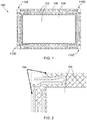
- FIG. 1 is a diagram illustrating a top view of an electrode plate 100 for a flowing electrolyte battery
- FIG. 2 is a diagram illustrating a partial bottom view of the electrode plate 100 of FIG. 1 , according to an embodiment of the present invention.
- the electrode plate 100 is planar and includes a frame 108 for housing an electrode 109.
- the electrode plate 100 includes a top surface 102 and a bottom surface 104.
- An edge 106 of a periphery of the bottom surface 104, and in particular the frame 108, is substantially flat to facilitate a good seal between the electrode plate 100 and a test jig for testing the electrode plate 100 for defects.
- the electrode plate 100 is depicted as being rectangular, it should be appreciated that other embodiments of electrode plates of the present invention may be any suitable shape.
- the frame 108 is made of a plastic material such as High-Density Polyethylene (HDPE).
- HDPE High-Density Polyethylene
- the frame 108 may be made of any material that is compatible with the flowing electrolyte and the electrode.
- the electrode plate 100 also includes frangible portions 110A, 110B, 110C, 110D formed adjacent each corner of the electrode plate 100. Although four frangible portions 110A, 110B, 110C, 110D are shown, it should be appreciated that other embodiments of electrode plates of the present invention may include one or more frangible portions. In addition, according to some embodiments, the frangible portions may be formed anywhere in the electrode plate, either along an edge of the electrode plate or at an internal section of the electrode plate.
- the frangible portions 110A, 110B, 110C, 110D are designed to be broken off, once the electrode plate 100 has been tested, to accommodate a manifold of a flowing electrolyte battery.
- An advantage of this arrangement is that it makes pre-assembly testing of the electrode plate 100 easier and more robust, as the electrode plate 100 including the frangible portions 110A, 110B, 110C, 110D defines a more regular shape including a smooth surface around its periphery to enable sealing against a test jig.
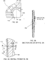
- FIG. 3A is a diagram illustrating a detailed top view of one corner of the electrode plate 100 of FIG. 1 , showing a single frangible portion 110C in more detail.
- FIG. 3B is a diagram illustrating a cross sectional view AA-AA of the corner of the electrode plate 100 of FIG. 3A.
- FIG. 3C is a diagram illustrating a detailed view of the cross section AA-AA of FIG. 3B .
- the other frangible portions 110A, 110B, 110D are similar to the frangible portion 110C.
- an interface between the frangible portion 110C and a remainder of the electrode plate 100 includes a groove 112.
- the groove 112 is a wedge shape defining an angle of approximately 30 degrees to an axis normal to the plane of the electrode plate 100. As shown, the groove 112 terminates 0.5mm from an edge of the electrode plate 100.
- the groove 112 may be any suitable shape so that the frangible portion 110C may be easily snapped off after testing of the electrode plate 100.
- the groove 112 is shown as being continuous, it should be appreciated that the groove 112 alternatively may be replaced with, for example, a series of small indentations.
- Various techniques for manufacturing frangible portions in materials such as polymers are well known in the art and can be applied to the present invention.
- An interface between the frangible portions 110A, 110B, 110C, 110D and a remainder of the electrode plate 100 is made generally smooth in order to connect to the manifold of the battery.
- the groove 112 does not extend into the bottom surface 104. Rather, the groove 112 stops approximately 0.3mm from the bottom surface 104. That enables the bottom surface 104 to maintain a seal with a test jig during testing of the electrode plate 100 and before the frangible portions 110A, 110B, 110C, 110D are broken off.
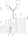
- FIG. 4 is a diagram illustrating a test jig 300 for testing the electrode plate 100, according to an embodiment of the present invention.
- the test jig 300 includes a pressure plate 310, a seal such as an o-ring 320, a vacuum plate 330, a press plate 340, a vacuum pump 350 and a gas detector 360.
- the electrode plate 100 under test is positioned in the test jig 300 between the pressure plate 310 and the vacuum plate 330.
- the pressure plate 310 applies pressure to the top surface 102 of the electrode plate 100 such that the edge 106 of the bottom surface 104 seals against the o-ring 320, which extends around the periphery of the electrode plate 100.
- a gas such as hydrogen
- a gas is pumped into a top cavity 302 formed between the pressure plate 310 and the electrode plate 100, the top cavity 302 being adjacent the top surface 102 of the electrode plate 100.
- a bottom cavity 304, adjacent the bottom surface 104 of the electrode plate 100, is then evacuated by the vacuum pump 350 which is also connected to the bottom cavity 304.
- the gas detector 360 may sound an alarm in order to signal to an operator that the electrode plate 100 is defective and should be discarded.
- the defective electrode plate 100 may be discarded automatically by the test jig 300.
- the bottom cavity 304, adjacent the bottom surface 104 of the electrode plate 100 is evacuated by the vacuum pump 350 which is also connected to the bottom cavity 304 and when the resulting vacuum reaches a set value, the pumping stops. If the electrode plate 100 is defective, for example if the electrode plate 100 has a crack or a hole, the set value of the vacuum drops and the electrode plate is identified as a faulty one. Upon detection of the pressure drop, a pressure switch can trigger an alarm in order to signal to an operator that the electrode plate 100 is defective and should be discarded. Or the defective electrode plate 100 may be discarded automatically by the test jig 300.
- a positive pressure can be used instead of a vacuum, where the positive pressure is applied in the top cavity 302 formed between the pressure plate 310 and the electrode plate 100.
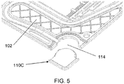
- FIG. 5 is a diagram illustrating a detailed top perspective view of the electrode plate 100 of FIG. 1 with the frangible portion 110C removed. As shown in FIG 5 , when the frangible portion 110C is removed, the electrode plate 100 defines a cut-away space 114 complementing a shape of the frangible portion 110C.
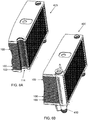
- FIG. 6A is a diagram illustrating a partial perspective view of an assembled cell stack of a flowing electrolyte battery 400, without a manifold, according to an embodiment of the present invention.
- FIG. 6B is a diagram illustrating a partial perspective view of the assembled cell stack of the flowing electrolyte battery 400 with a manifold 410, according to an embodiment of the present invention.
- the cut-away space 114 of each electrode plate 100 complements and receives the shape of the manifold 410 of the battery 400.
- electrolyte then flows to (or from) the manifold 410 and from (or to, respectively) the battery half cell cavities defined between adjacent electrode plates 100.
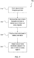
- FIG. 7 is a flow diagram illustrating a method 700 for manufacturing an electrode plate according to an embodiment of the present invention. At step 710, one or more frangible portions are formed in the electrode plate.
- the one or more frangible portions are removed from the electrode plate to define one or more cut-away regions.
- the electrode plate is positioned in a battery cell stack.
- one or more manifolds are attached to the battery cell stack adjacent the one or more cut-away regions.
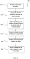
- FIG. 8 is a flow diagram illustrating a method 800 for testing an electrode plate of a flowing electrolyte battery according to an embodiment of the present invention.
- a seal is provided around a periphery of the electrode plate, wherein the periphery includes a frangible portion against which the seal is provided.
- a gas is applied adjacent a surface on a first side of the electrode plate.
- step 830 detecting whether there is a presence of the gas adjacent a surface on a second side of the electrode plate is performed. If a presence of the gas is detected, then for example it is assumed that the electrode plate is defective and the electrode plate is discarded.
- the frangible portion is removed from the electrode plate, thus defining a cut-away region of the electrode plate.
- the electrode plate is positioned in a battery cell stack.
- a manifold is attached to the cell stack adjacent the cut-away region of the electrode plate.
- advantages of some embodiments of the present invention comprise an electrode plate including a smooth, substantially flat, periphery surface integrated with a frangible portion to facilitate efficient and robust manufacture and testing of the electrode plate. After successful testing, the frangible portion is removed so that a plurality of electrode plates can interface with a manifold of a battery.
Landscapes
- Engineering & Computer Science (AREA)
- Manufacturing & Machinery (AREA)
- Chemical & Material Sciences (AREA)
- Chemical Kinetics & Catalysis (AREA)
- Electrochemistry (AREA)
- General Chemical & Material Sciences (AREA)
- Life Sciences & Earth Sciences (AREA)
- Sustainable Development (AREA)
- Sustainable Energy (AREA)
- Physics & Mathematics (AREA)
- General Physics & Mathematics (AREA)
- Fuel Cell (AREA)
- Hybrid Cells (AREA)
- Secondary Cells (AREA)
Description
- The present invention relates to electrode plates. In particular, although not exclusively, the invention relates to an electrode plate for a flowing electrolyte battery and methods for manufacturing and testing such a plate.
- Batteries used in stand alone power supply systems are commonly lead-acid batteries. However, lead-acid batteries have limitations in terms of performance and environmental safety. For example, typical lead-acid batteries often have very short lifetimes in hot climate conditions, especially when they are occasionally fully discharged. Lead-acid batteries are also environmentally hazardous, since lead is a major component of lead-acid batteries and can cause serious environmental problems during manufacturing and disposal.
- Flowing electrolyte batteries, such as zinc-bromine batteries, zinc-chlorine batteries, and vanadium flow batteries, offer a potential to overcome the above mentioned limitations of lead-acid batteries. In particular, the useful lifetime of flowing electrolyte batteries is not affected by deep discharge applications, and the energy to weight ratio of flowing electrolyte batteries is up to six times higher than that of lead-acid batteries.
- A flowing electrolyte battery, like a lead acid battery, comprises a stack of cells that produce a total voltage higher than that of individual cells. But unlike a lead acid battery, cells in a flowing electrolyte battery are hydraulically connected through an electrolyte circulation path.
- The cell stack often comprises a stack of electrode plates separated by separator plates to define a plurality of half cells. The half cells each comprise an electrode plate, an adjacent separator plate and a capillary tube. The half cells are generally rectangular in top plan view, but have a cut-away region at corners of the electrode plate to accommodate a manifold for pumping electrolyte into and out of the battery. However, due to an often complex shape formed by the cut-away regions, testing of individual electrode plates before they are assembled into a battery can be difficult.
- US Patent application publication
US 2008/081247 A1 of Nakaishi Hiroyuki [JP] et al, dated 3 April 2008 , disclosed a cell frame for a redox flow battery that prevents leakage of electrolyte out of the cell frame. However, that application did not disclose an effective means for testing of individual electrode plates. - Japanese patent application publication
JP 2005 317328 A - There is therefore a need to overcome or alleviate problems associated with manufacturing and testing electrode plates of flowing electrolyte batteries of the prior art.
- It is an object, of some embodiments of the present invention, to provide consumers with improvements and advantages over the above described prior art, and/or overcome and alleviate one or more of the above described disadvantages of the prior art, and/or provide a useful commercial choice.
- In one form, although not necessarily the only or broadest form, the present invention resides in an electrode plate for a flowing electrolyte battery, wherein the electrode plate includes one or more frangible portions connected to the electrode plate, wherein an interface between the one or more frangible portions and a remainder of the electrode plate includes a groove or a series of small indentations, and wherein the remainder of the electrode plate defines a cut-away space that complements a shape of a manifold of the battery.
- Preferably, the one or more frangible portions are located adjacent one or more corners of the electrode plate.
- Preferably, the electrode plate is planar and includes a top surface and a bottom surface.
- Preferably, an edge of a periphery of the bottom surface is substantially flat for sealing against a seal of a test rig.
- Preferably, the groove is formed in a top surface of the electrode plate.
- Preferably, the frangible portions are defined in a polymer frame of the electrode plate.
- Preferably, the polymer is High-Density Polyethylene (HDPE).
- According to another aspect, the present invention includes a method of manufacturing and testing an electrode plate and assembling a battery cell stack for a flowing electrolyte battery, the method comprising:forming one or more frangible portions in the electrode plate, wherein an interface between the one or more frangible portions and a remainder of the electrode plate includes a groove or a series of small indentations;providing a seal around a periphery of the electrode plate, wherein the periphery extends across the one or more frangible portions; applying a gas adjacent a surface on a first side of the electrode plate; detecting whether there is a presence of the gas adjacent a surface on a second side of the electrode plate; removing the one or more frangible portions from the electrode plate to define one or more cut-away regions; positioning the electrode plate in the battery cell stack; and attaching one or more manifolds to the battery cell stack adjacent the one or more cut-away regions.
- Preferably, the gas is applied adjacent a top surface of the electrode plate and further comprising evacuating adjacent a bottom surface of the electrode plate.
- Preferably, the gas is hydrogen.
- Preferably, evacuating adjacent a bottom surface of the electrode plate is performed using a vacuum pump.
- Preferably, the one or more frangible portions are defined in a High-Density Polyethylene (HDPE) frame of the electrode plate.
- To assist in understanding the invention and to enable a person skilled in the art to put the invention into practical effect, preferred embodiments of the invention are described below by way of example only with reference to the accompanying drawings, in which:
-
FIG. 1 is a diagram illustrating a top view of an electrode plate for a flowing electrolyte battery according to an embodiment of the present invention; -
FIG. 2 is a diagram illustrating a partial bottom view of the electrode plate ofFIG. 1 ; -
FIG. 3A is a diagram illustrating a detailed top view of the electrode plate ofFIG. 1 ; -
FIG. 3B is a diagram illustrating a cross sectional view AA-AA of the electrode plate ofFIG. 3A ; -
FIG. 3C is a diagram illustrating a detailed view of the cross section AA-AA ofFIG. 3B ; -
FIG. 4 is a diagram illustrating a test jig for testing the electrode plate ofFIG. 1 according to an embodiment of the present invention; -
FIG. 5 is a diagram illustrating a detailed top perspective view of the electrode plate ofFIG. 1 with a frangible portion removed; -
FIG. 6A is a diagram illustrating a partial perspective view of an assembled cell stack of a flowing electrolyte battery without a manifold, according to an embodiment of the present invention; and -
FIG. 6B is a diagram illustrating a partial perspective view of an assembled cell stack of a flowing electrolyte battery with a manifold installed, according to an embodiment of the present invention. -
FIG. 7 is a process flow diagram illustrating a method of manufacturing an electrode plate of a flowing electrolyte battery, according to an embodiment of the present invention. -
FIG. 8 is a process flow diagram illustrating a method of testing an electrode plate of a flowing electrolyte battery, according to an embodiment of the present invention. - Elements of the invention are illustrated in concise outline form in the drawings, showing only those specific details that are necessary to understanding the embodiments of the present invention, but so as not to clutter the disclosure with excessive detail that will be obvious to those of ordinary skill in the art in light of the present description.
- In this patent specification, adjectives such as first and second, left and right, front and back, top and bottom, etc., are used solely to define one element or method step from another element or method step without necessarily requiring a specific relative position or sequence that is described by the adjectives. Words such as "comprises" or "includes" are not used to define an exclusive set of elements or method steps. Rather, such words merely define a minimum set of elements or method steps included in a particular embodiment of the present invention.
-
FIG. 1 is a diagram illustrating a top view of anelectrode plate 100 for a flowing electrolyte battery, andFIG. 2 is a diagram illustrating a partial bottom view of theelectrode plate 100 ofFIG. 1 , according to an embodiment of the present invention. - Referring to
FIGs. 1 and 2 theelectrode plate 100 is planar and includes aframe 108 for housing anelectrode 109. Theelectrode plate 100 includes atop surface 102 and abottom surface 104. Anedge 106 of a periphery of thebottom surface 104, and in particular theframe 108, is substantially flat to facilitate a good seal between theelectrode plate 100 and a test jig for testing theelectrode plate 100 for defects. Although theelectrode plate 100 is depicted as being rectangular, it should be appreciated that other embodiments of electrode plates of the present invention may be any suitable shape. - In one embodiment, the
frame 108 is made of a plastic material such as High-Density Polyethylene (HDPE). However it should be appreciated that theframe 108 may be made of any material that is compatible with the flowing electrolyte and the electrode. - The
electrode plate 100, and in particular theframe 108, also includesfrangible portions electrode plate 100. Although fourfrangible portions - The
frangible portions electrode plate 100 has been tested, to accommodate a manifold of a flowing electrolyte battery. An advantage of this arrangement is that it makes pre-assembly testing of theelectrode plate 100 easier and more robust, as theelectrode plate 100 including thefrangible portions -
FIG. 3A is a diagram illustrating a detailed top view of one corner of theelectrode plate 100 ofFIG. 1 , showing a singlefrangible portion 110C in more detail.FIG. 3B is a diagram illustrating a cross sectional view AA-AA of the corner of theelectrode plate 100 ofFIG. 3A. FIG. 3C is a diagram illustrating a detailed view of the cross section AA-AA ofFIG. 3B . The otherfrangible portions frangible portion 110C. - Referring to
FIGs. 3A, 3B and 3C , an interface between thefrangible portion 110C and a remainder of theelectrode plate 100, includes agroove 112. In one embodiment thegroove 112 is a wedge shape defining an angle of approximately 30 degrees to an axis normal to the plane of theelectrode plate 100. As shown, thegroove 112 terminates 0.5mm from an edge of theelectrode plate 100. However it should be appreciated that thegroove 112 may be any suitable shape so that thefrangible portion 110C may be easily snapped off after testing of theelectrode plate 100. In addition, although thegroove 112 is shown as being continuous, it should be appreciated that thegroove 112 alternatively may be replaced with, for example, a series of small indentations. Various techniques for manufacturing frangible portions in materials such as polymers are well known in the art and can be applied to the present invention. - An interface between the
frangible portions electrode plate 100 is made generally smooth in order to connect to the manifold of the battery. In addition, thegroove 112 does not extend into thebottom surface 104. Rather, thegroove 112 stops approximately 0.3mm from thebottom surface 104. That enables thebottom surface 104 to maintain a seal with a test jig during testing of theelectrode plate 100 and before thefrangible portions - The
electrode plate 100 is tested by placing it in a test jig.FIG. 4 is a diagram illustrating atest jig 300 for testing theelectrode plate 100, according to an embodiment of the present invention. Thetest jig 300 includes apressure plate 310, a seal such as an o-ring 320, avacuum plate 330, apress plate 340, avacuum pump 350 and agas detector 360. Theelectrode plate 100 under test is positioned in thetest jig 300 between thepressure plate 310 and thevacuum plate 330. Thepressure plate 310 applies pressure to thetop surface 102 of theelectrode plate 100 such that theedge 106 of thebottom surface 104 seals against the o-ring 320, which extends around the periphery of theelectrode plate 100. - During a test, a gas, such as hydrogen, is pumped into a
top cavity 302 formed between thepressure plate 310 and theelectrode plate 100, thetop cavity 302 being adjacent thetop surface 102 of theelectrode plate 100. Abottom cavity 304, adjacent thebottom surface 104 of theelectrode plate 100, is then evacuated by thevacuum pump 350 which is also connected to thebottom cavity 304. If theelectrode plate 100 is defective, for example if theelectrode plate 100 has a crack or a hole, the gas flows from thetop cavity 302 to thebottom cavity 304 and is detected by thegas detector 360. Upon detection of the gas, thegas detector 360 may sound an alarm in order to signal to an operator that theelectrode plate 100 is defective and should be discarded. Alternatively, thedefective electrode plate 100 may be discarded automatically by thetest jig 300. Alternatively, during a test, thebottom cavity 304, adjacent thebottom surface 104 of theelectrode plate 100, is evacuated by thevacuum pump 350 which is also connected to thebottom cavity 304 and when the resulting vacuum reaches a set value, the pumping stops. If theelectrode plate 100 is defective, for example if theelectrode plate 100 has a crack or a hole, the set value of the vacuum drops and the electrode plate is identified as a faulty one. Upon detection of the pressure drop, a pressure switch can trigger an alarm in order to signal to an operator that theelectrode plate 100 is defective and should be discarded. Or thedefective electrode plate 100 may be discarded automatically by thetest jig 300. As yet another alternative, as will be understood by those having ordinary skill in the art, a positive pressure can be used instead of a vacuum, where the positive pressure is applied in thetop cavity 302 formed between thepressure plate 310 and theelectrode plate 100. - After the
electrode plate 100 has been tested, each of thefrangible portions top surface 104 of theelectrode plate 100.FIG. 5 is a diagram illustrating a detailed top perspective view of theelectrode plate 100 ofFIG. 1 with thefrangible portion 110C removed. As shown inFIG 5 , when thefrangible portion 110C is removed, theelectrode plate 100 defines a cut-awayspace 114 complementing a shape of thefrangible portion 110C. - In use, once the frangible portion 110 has been removed from the
electrode plate 100, a plurality ofelectrodes 100 are assembled together to form a flowing electrolyte battery.FIG. 6A is a diagram illustrating a partial perspective view of an assembled cell stack of a flowingelectrolyte battery 400, without a manifold, according to an embodiment of the present invention.FIG. 6B is a diagram illustrating a partial perspective view of the assembled cell stack of the flowingelectrolyte battery 400 with a manifold 410, according to an embodiment of the present invention. As shown inFIGs. 6A and 6B , the cut-awayspace 114 of eachelectrode plate 100 complements and receives the shape of themanifold 410 of thebattery 400. During use, electrolyte then flows to (or from) themanifold 410 and from (or to, respectively) the battery half cell cavities defined betweenadjacent electrode plates 100. -
FIG. 7 is a flow diagram illustrating amethod 700 for manufacturing an electrode plate according to an embodiment of the present invention. Atstep 710, one or more frangible portions are formed in the electrode plate. - At
step 720, the one or more frangible portions are removed from the electrode plate to define one or more cut-away regions. - At
step 730, the electrode plate is positioned in a battery cell stack. - At
step 740, one or more manifolds are attached to the battery cell stack adjacent the one or more cut-away regions. -
FIG. 8 is a flow diagram illustrating amethod 800 for testing an electrode plate of a flowing electrolyte battery according to an embodiment of the present invention. Atstep 810, a seal is provided around a periphery of the electrode plate, wherein the periphery includes a frangible portion against which the seal is provided. - At
step 820, a gas is applied adjacent a surface on a first side of the electrode plate. - At
step 830, detecting whether there is a presence of the gas adjacent a surface on a second side of the electrode plate is performed. If a presence of the gas is detected, then for example it is assumed that the electrode plate is defective and the electrode plate is discarded. - Assuming that a presence of the gas is not detected on the second side, or that only an acceptably low concentration of the gas is detected, then at
step 840 the frangible portion is removed from the electrode plate, thus defining a cut-away region of the electrode plate. - At
step 850, the electrode plate is positioned in a battery cell stack. - Finally, at
step 860, a manifold is attached to the cell stack adjacent the cut-away region of the electrode plate. - In summary, advantages of some embodiments of the present invention comprise an electrode plate including a smooth, substantially flat, periphery surface integrated with a frangible portion to facilitate efficient and robust manufacture and testing of the electrode plate. After successful testing, the frangible portion is removed so that a plurality of electrode plates can interface with a manifold of a battery.
Claims (12)
- An electrode plate (100) for a flowing electrolyte battery (400), wherein the electrode plate (100) includes one or more frangible portions (110A) connected to the electrode plate (100), wherein an interface between the one or more frangible portions (110A) and a remainder of the electrode plate (100) includes a groove (112) or a series of small indentations, and wherein the remainder of the electrode plate (100) defines a cut-away space (114) that complements a shape of a manifold (410) of the battery (400).
- The electrode plate (100) of claim 1, wherein the one or more frangible portions (110A) are located adjacent one or more corners of the electrode plate (100).
- The electrode plate (100) of claim 1, wherein the electrode plate (100) is planar and includes a top surface (102) and a bottom surface (104).
- The electrode plate (100) of claim 3, wherein an edge of a periphery of the bottom surface (104) is substantially flat for sealing against a seal of a test jig (300).
- The electrode plate (100) of claim 1, wherein the groove (112) is formed in a top surface (102) of the electrode plate (100).
- The electrode plate (100) of claim 1, wherein the one or more frangible portions (110A) are defined in a polymer frame (108) of the electrode plate (100).
- The electrode plate (100) of claim 6, wherein the polymer is High-Density Polyethylene (HDPE).
- A method of manufacturing and testing an electrode plate (100) and assembling a battery cell stack for a flowing electrolyte battery (400), the method comprising:forming one or more frangible portions (110A) in the electrode plate (100), wherein an interface between the one or more frangible portions (110A) and a remainder of the electrode plate (100) includes a groove (112) or a series of small indentations;providing a seal around a periphery of the electrode plate (100), wherein the periphery extends across the one or more frangible portions (110A);applying a gas adjacent a surface on a first side of the electrode plate (100);detecting whether there is a presence of the gas adjacent a surface on a second side of the electrode plate (100);removing the one or more frangible portions (110A) from the electrode plate (100) to define one or more cut-away regions (114);positioning the electrode plate (100) in the battery cell stack; andattaching one or more manifolds (410) to the battery cell stack adjacent the one or more cut-away regions (114).
- The method of claim 8, wherein the gas is applied adjacent a top surface (102) of the electrode plate (100) and further comprising evacuating adjacent a bottom surface (104) of the electrode plate (100).
- The method of claim 8, wherein the gas is hydrogen.
- The method of claim 9, wherein evacuating adjacent a bottom surface (104) of the electrode plate (100) is performed using a vacuum pump.
- The method of claim 8, wherein the one or more frangible portions (110A) are defined in a High-Density Polyethylene (HDPE) frame (108) of the electrode plate (100).
Applications Claiming Priority (2)
| Application Number | Priority Date | Filing Date | Title |
|---|---|---|---|
| AU2013903965A AU2013903965A0 (en) | 2013-10-15 | Electrode plate | |
| PCT/AU2014/000964 WO2015054721A1 (en) | 2013-10-15 | 2014-10-14 | Electrode plate and methods for manufacturing and testing an electrode plate |
Publications (3)
| Publication Number | Publication Date |
|---|---|
| EP3058609A1 EP3058609A1 (en) | 2016-08-24 |
| EP3058609A4 EP3058609A4 (en) | 2017-05-10 |
| EP3058609B1 true EP3058609B1 (en) | 2018-08-15 |
Family
ID=52827444
Family Applications (1)
| Application Number | Title | Priority Date | Filing Date |
|---|---|---|---|
| EP14854312.7A Active EP3058609B1 (en) | 2013-10-15 | 2014-10-14 | Electrode plate and methods for manufacturing and testing an electrode plate |
Country Status (6)
| Country | Link |
|---|---|
| US (1) | US9899689B2 (en) |
| EP (1) | EP3058609B1 (en) |
| JP (1) | JP6387092B2 (en) |
| CN (1) | CN105637680B (en) |
| AU (1) | AU2014336948B2 (en) |
| WO (1) | WO2015054721A1 (en) |
Families Citing this family (2)
| Publication number | Priority date | Publication date | Assignee | Title |
|---|---|---|---|---|
| KR101802749B1 (en) * | 2016-10-20 | 2017-12-28 | 주식회사 에이치투 | Flow Battery Stack including Capillary Tube |
| CN112414629A (en) * | 2020-11-22 | 2021-02-26 | 上海神力科技有限公司 | Leakage detection method for bipolar plate of fuel cell |
Family Cites Families (13)
| Publication number | Priority date | Publication date | Assignee | Title |
|---|---|---|---|---|
| BE533034A (en) * | 1953-11-04 | |||
| US5008162A (en) * | 1988-05-11 | 1991-04-16 | Klaus Tomantschger | Test cell structure |
| US5591538A (en) * | 1995-07-07 | 1997-01-07 | Zbb Technologies, Inc. | Zinc-bromine battery with non-flowing electrolyte |
| JP2000285909A (en) * | 1999-03-31 | 2000-10-13 | Mitsubishi Cable Ind Ltd | Testing device of electrode plate for lithium ion secondary battery |
| JP3682244B2 (en) * | 2001-06-12 | 2005-08-10 | 住友電気工業株式会社 | Cell frame for redox flow battery and redox flow battery |
| JP2005093215A (en) * | 2003-09-17 | 2005-04-07 | Dainippon Ink & Chem Inc | Manufacturing method of separator member for fuel cell |
| JP4830264B2 (en) * | 2004-04-28 | 2011-12-07 | Dic株式会社 | Manufacturing method of fuel cell separator |
| DE102004037575A1 (en) * | 2004-08-03 | 2006-03-16 | Daimlerchrysler Ag | Test device and test method for production-integrated, non-destructive testing, in particular of membrane-electrode assemblies for use in fuel cells |
| CN100504331C (en) * | 2004-12-16 | 2009-06-24 | 上海神力科技有限公司 | Vacuum leak detector for fuel cell membrane electrode |
| JP2007115481A (en) * | 2005-10-19 | 2007-05-10 | Nissan Motor Co Ltd | Solid oxide fuel cell board |
| US8293390B2 (en) | 2007-03-28 | 2012-10-23 | Redflow Pty Ltd | Cell stack for a flowing electrolyte battery |
| WO2010020013A1 (en) * | 2008-08-22 | 2010-02-25 | Redflow Pty Ltd | Integral manifold |
| JP2011072958A (en) * | 2009-10-01 | 2011-04-14 | Mitsubishi Heavy Ind Ltd | Inspection method and inspection device of hydrogen separation film, and method and apparatus for manufacturing hydrogen separation film module |
-
2014
- 2014-10-14 US US15/029,275 patent/US9899689B2/en active Active
- 2014-10-14 AU AU2014336948A patent/AU2014336948B2/en active Active
- 2014-10-14 CN CN201480057044.6A patent/CN105637680B/en active Active
- 2014-10-14 EP EP14854312.7A patent/EP3058609B1/en active Active
- 2014-10-14 JP JP2016524014A patent/JP6387092B2/en not_active Expired - Fee Related
- 2014-10-14 WO PCT/AU2014/000964 patent/WO2015054721A1/en active Application Filing
Non-Patent Citations (1)
| Title |
|---|
| None * |
Also Published As
| Publication number | Publication date |
|---|---|
| JP2016533620A (en) | 2016-10-27 |
| EP3058609A1 (en) | 2016-08-24 |
| US9899689B2 (en) | 2018-02-20 |
| CN105637680B (en) | 2019-09-06 |
| WO2015054721A1 (en) | 2015-04-23 |
| US20160254553A1 (en) | 2016-09-01 |
| AU2014336948A1 (en) | 2016-04-21 |
| EP3058609A4 (en) | 2017-05-10 |
| AU2014336948B2 (en) | 2018-04-12 |
| JP6387092B2 (en) | 2018-09-05 |
| CN105637680A (en) | 2016-06-01 |
Similar Documents
| Publication | Publication Date | Title |
|---|---|---|
| CN114072958B (en) | End cover assembly, battery cell, battery pack and device | |
| US10826083B2 (en) | Fuel cell assemblies with improved reactant flow | |
| EP3279990B1 (en) | Separator for fuel cells and method for producing same | |
| US20120270131A1 (en) | Fuel cell unit and fuel cell | |
| US9812728B2 (en) | Fuel-cell single cell | |
| JP4708101B2 (en) | Fuel cell voltage detection structure | |
| US11088373B2 (en) | Seal for solid polymer electrolyte fuel cell | |
| CN111630707B (en) | Coolant distribution interface for battery module housing | |
| EP3058609B1 (en) | Electrode plate and methods for manufacturing and testing an electrode plate | |
| JP2012099368A (en) | Cell stack, cell frame, redox flow battery, and cell stack manufacturing method | |
| JP6090791B2 (en) | Electrolyte membrane / electrode structure with resin frame for fuel cells | |
| WO2018105091A1 (en) | Redox flow battery | |
| US10135078B2 (en) | Current collector for fuel cell, and fuel cell stack | |
| US8709624B2 (en) | Energy storage device package | |
| JP2010170785A (en) | Fuel cell and its assembling method | |
| JP2005044658A (en) | Fuel cell stack, repairing method of fuel cell stack, and short circuit member electrically short-circuiting operation defective unit cell in fuel cell stack | |
| KR20230059516A (en) | Battery module and battery pack monitoring the insulation of pouch-type battery cells | |
| KR20230132728A (en) | Connecting tab with an integrated burst valve for a battery cell and a battery cell comprising the same | |
| KR20230082217A (en) | Pouch type secondary battery | |
| CN117727964A (en) | Galvanic pile and flow battery | |
| JP2007234389A (en) | Fuel cell and its manufacturing method |
Legal Events
| Date | Code | Title | Description |
|---|---|---|---|
| PUAI | Public reference made under article 153(3) epc to a published international application that has entered the european phase |
Free format text: ORIGINAL CODE: 0009012 |
|
| 17P | Request for examination filed |
Effective date: 20160511 |
|
| AK | Designated contracting states |
Kind code of ref document: A1 Designated state(s): AL AT BE BG CH CY CZ DE DK EE ES FI FR GB GR HR HU IE IS IT LI LT LU LV MC MK MT NL NO PL PT RO RS SE SI SK SM TR |
|
| AX | Request for extension of the european patent |
Extension state: BA ME |
|
| RAP1 | Party data changed (applicant data changed or rights of an application transferred) |
Owner name: REDFLOW R & D PTY LTD. |
|
| DAX | Request for extension of the european patent (deleted) | ||
| A4 | Supplementary search report drawn up and despatched |
Effective date: 20170412 |
|
| RIC1 | Information provided on ipc code assigned before grant |
Ipc: H01M 8/0273 20160101ALI20170404BHEP Ipc: H01M 8/04276 20160101ALI20170404BHEP Ipc: H01M 10/04 20060101ALI20170404BHEP Ipc: H01M 10/42 20060101ALI20170404BHEP Ipc: H01M 4/00 20060101AFI20170404BHEP Ipc: H01M 8/18 20060101ALI20170404BHEP Ipc: H01M 2/38 20060101ALN20170404BHEP Ipc: H01M 8/0286 20160101ALI20170404BHEP Ipc: H01M 8/20 20060101ALI20170404BHEP Ipc: H01M 10/36 20100101ALI20170404BHEP Ipc: G01M 3/02 20060101ALI20170404BHEP |
|
| STAA | Information on the status of an ep patent application or granted ep patent |
Free format text: STATUS: EXAMINATION IS IN PROGRESS |
|
| 17Q | First examination report despatched |
Effective date: 20171214 |
|
| GRAP | Despatch of communication of intention to grant a patent |
Free format text: ORIGINAL CODE: EPIDOSNIGR1 |
|
| STAA | Information on the status of an ep patent application or granted ep patent |
Free format text: STATUS: GRANT OF PATENT IS INTENDED |
|
| RIC1 | Information provided on ipc code assigned before grant |
Ipc: H01M 10/36 20100101ALI20180209BHEP Ipc: H01M 10/42 20060101ALI20180209BHEP Ipc: G01M 3/02 20060101ALI20180209BHEP Ipc: H01M 8/04276 20160101ALI20180209BHEP Ipc: H01M 8/18 20060101ALI20180209BHEP Ipc: H01M 8/0273 20160101ALI20180209BHEP Ipc: H01M 2/38 20060101ALN20180209BHEP Ipc: H01M 4/00 20060101AFI20180209BHEP Ipc: H01M 10/04 20060101ALI20180209BHEP Ipc: H01M 8/20 20060101ALI20180209BHEP Ipc: H01M 8/0286 20160101ALI20180209BHEP |
|
| INTG | Intention to grant announced |
Effective date: 20180315 |
|
| GRAS | Grant fee paid |
Free format text: ORIGINAL CODE: EPIDOSNIGR3 |
|
| GRAA | (expected) grant |
Free format text: ORIGINAL CODE: 0009210 |
|
| STAA | Information on the status of an ep patent application or granted ep patent |
Free format text: STATUS: THE PATENT HAS BEEN GRANTED |
|
| AK | Designated contracting states |
Kind code of ref document: B1 Designated state(s): AL AT BE BG CH CY CZ DE DK EE ES FI FR GB GR HR HU IE IS IT LI LT LU LV MC MK MT NL NO PL PT RO RS SE SI SK SM TR |
|
| REG | Reference to a national code |
Ref country code: CH Ref legal event code: EP Ref country code: GB Ref legal event code: FG4D Ref country code: AT Ref legal event code: REF Ref document number: 1030799 Country of ref document: AT Kind code of ref document: T Effective date: 20180815 |
|
| REG | Reference to a national code |
Ref country code: IE Ref legal event code: FG4D |
|
| REG | Reference to a national code |
Ref country code: DE Ref legal event code: R096 Ref document number: 602014030637 Country of ref document: DE |
|
| REG | Reference to a national code |
Ref country code: FR Ref legal event code: PLFP Year of fee payment: 5 |
|
| REG | Reference to a national code |
Ref country code: NL Ref legal event code: MP Effective date: 20180815 |
|
| REG | Reference to a national code |
Ref country code: LT Ref legal event code: MG4D |
|
| REG | Reference to a national code |
Ref country code: AT Ref legal event code: MK05 Ref document number: 1030799 Country of ref document: AT Kind code of ref document: T Effective date: 20180815 |
|
| PG25 | Lapsed in a contracting state [announced via postgrant information from national office to epo] |
Ref country code: LT Free format text: LAPSE BECAUSE OF FAILURE TO SUBMIT A TRANSLATION OF THE DESCRIPTION OR TO PAY THE FEE WITHIN THE PRESCRIBED TIME-LIMIT Effective date: 20180815 Ref country code: RS Free format text: LAPSE BECAUSE OF FAILURE TO SUBMIT A TRANSLATION OF THE DESCRIPTION OR TO PAY THE FEE WITHIN THE PRESCRIBED TIME-LIMIT Effective date: 20180815 Ref country code: AT Free format text: LAPSE BECAUSE OF FAILURE TO SUBMIT A TRANSLATION OF THE DESCRIPTION OR TO PAY THE FEE WITHIN THE PRESCRIBED TIME-LIMIT Effective date: 20180815 Ref country code: IS Free format text: LAPSE BECAUSE OF FAILURE TO SUBMIT A TRANSLATION OF THE DESCRIPTION OR TO PAY THE FEE WITHIN THE PRESCRIBED TIME-LIMIT Effective date: 20181215 Ref country code: GR Free format text: LAPSE BECAUSE OF FAILURE TO SUBMIT A TRANSLATION OF THE DESCRIPTION OR TO PAY THE FEE WITHIN THE PRESCRIBED TIME-LIMIT Effective date: 20181116 Ref country code: NO Free format text: LAPSE BECAUSE OF FAILURE TO SUBMIT A TRANSLATION OF THE DESCRIPTION OR TO PAY THE FEE WITHIN THE PRESCRIBED TIME-LIMIT Effective date: 20181115 Ref country code: FI Free format text: LAPSE BECAUSE OF FAILURE TO SUBMIT A TRANSLATION OF THE DESCRIPTION OR TO PAY THE FEE WITHIN THE PRESCRIBED TIME-LIMIT Effective date: 20180815 Ref country code: SE Free format text: LAPSE BECAUSE OF FAILURE TO SUBMIT A TRANSLATION OF THE DESCRIPTION OR TO PAY THE FEE WITHIN THE PRESCRIBED TIME-LIMIT Effective date: 20180815 Ref country code: NL Free format text: LAPSE BECAUSE OF FAILURE TO SUBMIT A TRANSLATION OF THE DESCRIPTION OR TO PAY THE FEE WITHIN THE PRESCRIBED TIME-LIMIT Effective date: 20180815 Ref country code: BG Free format text: LAPSE BECAUSE OF FAILURE TO SUBMIT A TRANSLATION OF THE DESCRIPTION OR TO PAY THE FEE WITHIN THE PRESCRIBED TIME-LIMIT Effective date: 20181115 |
|
| PG25 | Lapsed in a contracting state [announced via postgrant information from national office to epo] |
Ref country code: HR Free format text: LAPSE BECAUSE OF FAILURE TO SUBMIT A TRANSLATION OF THE DESCRIPTION OR TO PAY THE FEE WITHIN THE PRESCRIBED TIME-LIMIT Effective date: 20180815 Ref country code: LV Free format text: LAPSE BECAUSE OF FAILURE TO SUBMIT A TRANSLATION OF THE DESCRIPTION OR TO PAY THE FEE WITHIN THE PRESCRIBED TIME-LIMIT Effective date: 20180815 Ref country code: AL Free format text: LAPSE BECAUSE OF FAILURE TO SUBMIT A TRANSLATION OF THE DESCRIPTION OR TO PAY THE FEE WITHIN THE PRESCRIBED TIME-LIMIT Effective date: 20180815 |
|
| PG25 | Lapsed in a contracting state [announced via postgrant information from national office to epo] |
Ref country code: CZ Free format text: LAPSE BECAUSE OF FAILURE TO SUBMIT A TRANSLATION OF THE DESCRIPTION OR TO PAY THE FEE WITHIN THE PRESCRIBED TIME-LIMIT Effective date: 20180815 Ref country code: IT Free format text: LAPSE BECAUSE OF FAILURE TO SUBMIT A TRANSLATION OF THE DESCRIPTION OR TO PAY THE FEE WITHIN THE PRESCRIBED TIME-LIMIT Effective date: 20180815 Ref country code: RO Free format text: LAPSE BECAUSE OF FAILURE TO SUBMIT A TRANSLATION OF THE DESCRIPTION OR TO PAY THE FEE WITHIN THE PRESCRIBED TIME-LIMIT Effective date: 20180815 Ref country code: ES Free format text: LAPSE BECAUSE OF FAILURE TO SUBMIT A TRANSLATION OF THE DESCRIPTION OR TO PAY THE FEE WITHIN THE PRESCRIBED TIME-LIMIT Effective date: 20180815 Ref country code: EE Free format text: LAPSE BECAUSE OF FAILURE TO SUBMIT A TRANSLATION OF THE DESCRIPTION OR TO PAY THE FEE WITHIN THE PRESCRIBED TIME-LIMIT Effective date: 20180815 Ref country code: PL Free format text: LAPSE BECAUSE OF FAILURE TO SUBMIT A TRANSLATION OF THE DESCRIPTION OR TO PAY THE FEE WITHIN THE PRESCRIBED TIME-LIMIT Effective date: 20180815 |
|
| REG | Reference to a national code |
Ref country code: DE Ref legal event code: R097 Ref document number: 602014030637 Country of ref document: DE |
|
| PG25 | Lapsed in a contracting state [announced via postgrant information from national office to epo] |
Ref country code: DK Free format text: LAPSE BECAUSE OF FAILURE TO SUBMIT A TRANSLATION OF THE DESCRIPTION OR TO PAY THE FEE WITHIN THE PRESCRIBED TIME-LIMIT Effective date: 20180815 Ref country code: SK Free format text: LAPSE BECAUSE OF FAILURE TO SUBMIT A TRANSLATION OF THE DESCRIPTION OR TO PAY THE FEE WITHIN THE PRESCRIBED TIME-LIMIT Effective date: 20180815 Ref country code: SM Free format text: LAPSE BECAUSE OF FAILURE TO SUBMIT A TRANSLATION OF THE DESCRIPTION OR TO PAY THE FEE WITHIN THE PRESCRIBED TIME-LIMIT Effective date: 20180815 |
|
| REG | Reference to a national code |
Ref country code: CH Ref legal event code: PL |
|
| PLBE | No opposition filed within time limit |
Free format text: ORIGINAL CODE: 0009261 |
|
| STAA | Information on the status of an ep patent application or granted ep patent |
Free format text: STATUS: NO OPPOSITION FILED WITHIN TIME LIMIT |
|
| REG | Reference to a national code |
Ref country code: BE Ref legal event code: MM Effective date: 20181031 |
|
| PG25 | Lapsed in a contracting state [announced via postgrant information from national office to epo] |
Ref country code: MC Free format text: LAPSE BECAUSE OF FAILURE TO SUBMIT A TRANSLATION OF THE DESCRIPTION OR TO PAY THE FEE WITHIN THE PRESCRIBED TIME-LIMIT Effective date: 20180815 Ref country code: LU Free format text: LAPSE BECAUSE OF NON-PAYMENT OF DUE FEES Effective date: 20181014 |
|
| 26N | No opposition filed |
Effective date: 20190516 |
|
| REG | Reference to a national code |
Ref country code: IE Ref legal event code: MM4A |
|
| PG25 | Lapsed in a contracting state [announced via postgrant information from national office to epo] |
Ref country code: BE Free format text: LAPSE BECAUSE OF NON-PAYMENT OF DUE FEES Effective date: 20181031 Ref country code: SI Free format text: LAPSE BECAUSE OF FAILURE TO SUBMIT A TRANSLATION OF THE DESCRIPTION OR TO PAY THE FEE WITHIN THE PRESCRIBED TIME-LIMIT Effective date: 20180815 Ref country code: LI Free format text: LAPSE BECAUSE OF NON-PAYMENT OF DUE FEES Effective date: 20181031 Ref country code: CH Free format text: LAPSE BECAUSE OF NON-PAYMENT OF DUE FEES Effective date: 20181031 |
|
| PG25 | Lapsed in a contracting state [announced via postgrant information from national office to epo] |
Ref country code: IE Free format text: LAPSE BECAUSE OF NON-PAYMENT OF DUE FEES Effective date: 20181014 |
|
| PG25 | Lapsed in a contracting state [announced via postgrant information from national office to epo] |
Ref country code: MT Free format text: LAPSE BECAUSE OF NON-PAYMENT OF DUE FEES Effective date: 20181014 |
|
| PG25 | Lapsed in a contracting state [announced via postgrant information from national office to epo] |
Ref country code: TR Free format text: LAPSE BECAUSE OF FAILURE TO SUBMIT A TRANSLATION OF THE DESCRIPTION OR TO PAY THE FEE WITHIN THE PRESCRIBED TIME-LIMIT Effective date: 20180815 |
|
| PG25 | Lapsed in a contracting state [announced via postgrant information from national office to epo] |
Ref country code: PT Free format text: LAPSE BECAUSE OF FAILURE TO SUBMIT A TRANSLATION OF THE DESCRIPTION OR TO PAY THE FEE WITHIN THE PRESCRIBED TIME-LIMIT Effective date: 20180815 |
|
| PG25 | Lapsed in a contracting state [announced via postgrant information from national office to epo] |
Ref country code: MK Free format text: LAPSE BECAUSE OF NON-PAYMENT OF DUE FEES Effective date: 20180815 Ref country code: HU Free format text: LAPSE BECAUSE OF FAILURE TO SUBMIT A TRANSLATION OF THE DESCRIPTION OR TO PAY THE FEE WITHIN THE PRESCRIBED TIME-LIMIT; INVALID AB INITIO Effective date: 20141014 Ref country code: CY Free format text: LAPSE BECAUSE OF FAILURE TO SUBMIT A TRANSLATION OF THE DESCRIPTION OR TO PAY THE FEE WITHIN THE PRESCRIBED TIME-LIMIT Effective date: 20180815 |
|
| PGFP | Annual fee paid to national office [announced via postgrant information from national office to epo] |
Ref country code: GB Payment date: 20231006 Year of fee payment: 10 |
|
| PGFP | Annual fee paid to national office [announced via postgrant information from national office to epo] |
Ref country code: FR Payment date: 20231009 Year of fee payment: 10 Ref country code: DE Payment date: 20231010 Year of fee payment: 10 |