EP3058109B1 - Top submerged injection lance for enhanced submerged combustion - Google Patents
Top submerged injection lance for enhanced submerged combustion Download PDFInfo
- Publication number
- EP3058109B1 EP3058109B1 EP14795672.6A EP14795672A EP3058109B1 EP 3058109 B1 EP3058109 B1 EP 3058109B1 EP 14795672 A EP14795672 A EP 14795672A EP 3058109 B1 EP3058109 B1 EP 3058109B1
- Authority
- EP
- European Patent Office
- Prior art keywords
- lance
- pipe
- flow
- gas
- oxygen
- Prior art date
- Legal status (The legal status is an assumption and is not a legal conclusion. Google has not performed a legal analysis and makes no representation as to the accuracy of the status listed.)
- Active
Links
- 238000002347 injection Methods 0.000 title claims description 33
- 239000007924 injection Substances 0.000 title claims description 33
- 238000002485 combustion reaction Methods 0.000 title description 26
- 239000007789 gas Substances 0.000 claims description 110
- QVGXLLKOCUKJST-UHFFFAOYSA-N atomic oxygen Chemical compound [O] QVGXLLKOCUKJST-UHFFFAOYSA-N 0.000 claims description 50
- 239000001301 oxygen Substances 0.000 claims description 50
- 229910052760 oxygen Inorganic materials 0.000 claims description 50
- 239000000446 fuel Substances 0.000 claims description 45
- 238000002156 mixing Methods 0.000 claims description 25
- 230000003247 decreasing effect Effects 0.000 claims description 8
- 230000000694 effects Effects 0.000 claims description 7
- 238000003466 welding Methods 0.000 claims description 7
- 230000010006 flight Effects 0.000 claims description 4
- 230000006870 function Effects 0.000 claims description 4
- 230000007423 decrease Effects 0.000 claims description 3
- 239000002893 slag Substances 0.000 description 46
- 238000001816 cooling Methods 0.000 description 25
- 239000000463 material Substances 0.000 description 14
- 238000007664 blowing Methods 0.000 description 13
- 239000007787 solid Substances 0.000 description 13
- 239000003570 air Substances 0.000 description 12
- 238000000034 method Methods 0.000 description 12
- RYGMFSIKBFXOCR-UHFFFAOYSA-N Copper Chemical compound [Cu] RYGMFSIKBFXOCR-UHFFFAOYSA-N 0.000 description 11
- 239000011248 coating agent Substances 0.000 description 11
- 238000000576 coating method Methods 0.000 description 11
- 230000008569 process Effects 0.000 description 11
- 229910052802 copper Inorganic materials 0.000 description 9
- 239000010949 copper Substances 0.000 description 9
- 238000005516 engineering process Methods 0.000 description 9
- XLYOFNOQVPJJNP-UHFFFAOYSA-N water Substances O XLYOFNOQVPJJNP-UHFFFAOYSA-N 0.000 description 9
- 229910000831 Steel Inorganic materials 0.000 description 8
- 239000003638 chemical reducing agent Substances 0.000 description 8
- 239000010410 layer Substances 0.000 description 8
- 239000000203 mixture Substances 0.000 description 8
- 239000010959 steel Substances 0.000 description 8
- 229910052751 metal Inorganic materials 0.000 description 7
- 239000002184 metal Substances 0.000 description 7
- 238000009853 pyrometallurgy Methods 0.000 description 6
- 239000000112 cooling gas Substances 0.000 description 5
- 239000012530 fluid Substances 0.000 description 5
- IJGRMHOSHXDMSA-UHFFFAOYSA-N Atomic nitrogen Chemical compound N#N IJGRMHOSHXDMSA-UHFFFAOYSA-N 0.000 description 4
- UQSXHKLRYXJYBZ-UHFFFAOYSA-N Iron oxide Chemical compound [Fe]=O UQSXHKLRYXJYBZ-UHFFFAOYSA-N 0.000 description 4
- 238000003723 Smelting Methods 0.000 description 4
- 230000009471 action Effects 0.000 description 4
- 238000001704 evaporation Methods 0.000 description 4
- 230000008020 evaporation Effects 0.000 description 4
- 230000001965 increasing effect Effects 0.000 description 4
- 238000012545 processing Methods 0.000 description 4
- 230000008901 benefit Effects 0.000 description 3
- 239000003245 coal Substances 0.000 description 3
- 239000012141 concentrate Substances 0.000 description 3
- 239000002826 coolant Substances 0.000 description 3
- 239000012809 cooling fluid Substances 0.000 description 3
- 239000007788 liquid Substances 0.000 description 3
- 238000004519 manufacturing process Methods 0.000 description 3
- 239000011236 particulate material Substances 0.000 description 3
- 229910000851 Alloy steel Inorganic materials 0.000 description 2
- 239000004215 Carbon black (E152) Substances 0.000 description 2
- CWYNVVGOOAEACU-UHFFFAOYSA-N Fe2+ Chemical compound [Fe+2] CWYNVVGOOAEACU-UHFFFAOYSA-N 0.000 description 2
- XEEYBQQBJWHFJM-UHFFFAOYSA-N Iron Chemical compound [Fe] XEEYBQQBJWHFJM-UHFFFAOYSA-N 0.000 description 2
- 239000012159 carrier gas Substances 0.000 description 2
- 239000000919 ceramic Substances 0.000 description 2
- 239000000498 cooling water Substances 0.000 description 2
- 238000013461 design Methods 0.000 description 2
- 230000002708 enhancing effect Effects 0.000 description 2
- 239000000295 fuel oil Substances 0.000 description 2
- 238000010438 heat treatment Methods 0.000 description 2
- 229930195733 hydrocarbon Natural products 0.000 description 2
- 150000002430 hydrocarbons Chemical class 0.000 description 2
- 230000006872 improvement Effects 0.000 description 2
- 238000002844 melting Methods 0.000 description 2
- 230000008018 melting Effects 0.000 description 2
- 238000012986 modification Methods 0.000 description 2
- 230000004048 modification Effects 0.000 description 2
- 229910052757 nitrogen Inorganic materials 0.000 description 2
- 239000011253 protective coating Substances 0.000 description 2
- 230000009467 reduction Effects 0.000 description 2
- 238000007670 refining Methods 0.000 description 2
- 238000007789 sealing Methods 0.000 description 2
- 229910001220 stainless steel Inorganic materials 0.000 description 2
- 238000012546 transfer Methods 0.000 description 2
- UGFAIRIUMAVXCW-UHFFFAOYSA-N Carbon monoxide Chemical compound [O+]#[C-] UGFAIRIUMAVXCW-UHFFFAOYSA-N 0.000 description 1
- 229910000881 Cu alloy Inorganic materials 0.000 description 1
- MYMOFIZGZYHOMD-UHFFFAOYSA-N Dioxygen Chemical compound O=O MYMOFIZGZYHOMD-UHFFFAOYSA-N 0.000 description 1
- 229910000805 Pig iron Inorganic materials 0.000 description 1
- 239000000654 additive Substances 0.000 description 1
- 229910045601 alloy Inorganic materials 0.000 description 1
- 239000000956 alloy Substances 0.000 description 1
- 238000003491 array Methods 0.000 description 1
- 238000000889 atomisation Methods 0.000 description 1
- 229910002091 carbon monoxide Inorganic materials 0.000 description 1
- 239000004568 cement Substances 0.000 description 1
- 238000005524 ceramic coating Methods 0.000 description 1
- 238000006243 chemical reaction Methods 0.000 description 1
- 239000011247 coating layer Substances 0.000 description 1
- 238000005260 corrosion Methods 0.000 description 1
- 230000007797 corrosion Effects 0.000 description 1
- 230000003628 erosive effect Effects 0.000 description 1
- 238000004880 explosion Methods 0.000 description 1
- 239000003546 flue gas Substances 0.000 description 1
- 230000004907 flux Effects 0.000 description 1
- 239000002529 flux (metallurgy) Substances 0.000 description 1
- 239000001257 hydrogen Substances 0.000 description 1
- 229910052739 hydrogen Inorganic materials 0.000 description 1
- 125000004435 hydrogen atom Chemical class [H]* 0.000 description 1
- 229910052500 inorganic mineral Inorganic materials 0.000 description 1
- 230000003993 interaction Effects 0.000 description 1
- 229910052742 iron Inorganic materials 0.000 description 1
- 239000003915 liquefied petroleum gas Substances 0.000 description 1
- 238000012423 maintenance Methods 0.000 description 1
- 239000000155 melt Substances 0.000 description 1
- 150000002739 metals Chemical class 0.000 description 1
- 239000011707 mineral Substances 0.000 description 1
- 239000012768 molten material Substances 0.000 description 1
- 230000002093 peripheral effect Effects 0.000 description 1
- 239000003209 petroleum derivative Substances 0.000 description 1
- 230000001681 protective effect Effects 0.000 description 1
- 239000011241 protective layer Substances 0.000 description 1
- 238000011084 recovery Methods 0.000 description 1
- 230000008439 repair process Effects 0.000 description 1
- 239000011369 resultant mixture Substances 0.000 description 1
- 238000007493 shaping process Methods 0.000 description 1
- 238000009987 spinning Methods 0.000 description 1
- 239000010935 stainless steel Substances 0.000 description 1
- 238000009628 steelmaking Methods 0.000 description 1
- 238000005728 strengthening Methods 0.000 description 1
Images

Classifications
-
- C—CHEMISTRY; METALLURGY
- C21—METALLURGY OF IRON
- C21C—PROCESSING OF PIG-IRON, e.g. REFINING, MANUFACTURE OF WROUGHT-IRON OR STEEL; TREATMENT IN MOLTEN STATE OF FERROUS ALLOYS
- C21C5/00—Manufacture of carbon-steel, e.g. plain mild steel, medium carbon steel or cast steel or stainless steel
- C21C5/28—Manufacture of steel in the converter
- C21C5/42—Constructional features of converters
- C21C5/46—Details or accessories
- C21C5/4606—Lances or injectors
- C21C5/4613—Refractory coated lances; Immersion lances
-
- F—MECHANICAL ENGINEERING; LIGHTING; HEATING; WEAPONS; BLASTING
- F27—FURNACES; KILNS; OVENS; RETORTS
- F27B—FURNACES, KILNS, OVENS, OR RETORTS IN GENERAL; OPEN SINTERING OR LIKE APPARATUS
- F27B3/00—Hearth-type furnaces, e.g. of reverberatory type; Tank furnaces
- F27B3/10—Details, accessories, or equipment peculiar to hearth-type furnaces
- F27B3/22—Arrangements of air or gas supply devices
- F27B3/225—Oxygen blowing
-
- F—MECHANICAL ENGINEERING; LIGHTING; HEATING; WEAPONS; BLASTING
- F27—FURNACES; KILNS; OVENS; RETORTS
- F27D—DETAILS OR ACCESSORIES OF FURNACES, KILNS, OVENS, OR RETORTS, IN SO FAR AS THEY ARE OF KINDS OCCURRING IN MORE THAN ONE KIND OF FURNACE
- F27D3/00—Charging; Discharging; Manipulation of charge
- F27D3/16—Introducing a fluid jet or current into the charge
- F27D2003/162—Introducing a fluid jet or current into the charge the fluid being an oxidant or a fuel
-
- F—MECHANICAL ENGINEERING; LIGHTING; HEATING; WEAPONS; BLASTING
- F27—FURNACES; KILNS; OVENS; RETORTS
- F27D—DETAILS OR ACCESSORIES OF FURNACES, KILNS, OVENS, OR RETORTS, IN SO FAR AS THEY ARE OF KINDS OCCURRING IN MORE THAN ONE KIND OF FURNACE
- F27D3/00—Charging; Discharging; Manipulation of charge
- F27D3/16—Introducing a fluid jet or current into the charge
- F27D2003/168—Introducing a fluid jet or current into the charge through a lance
- F27D2003/169—Construction of the lance, e.g. lances for injecting particles
Definitions
- This invention relates to top submerged injecting lances for use in molten bath pyro-metallurgical operations.
- Molten bath smelting operations utilize several different arrangements for the supply of the gas.
- these operations involve direct injection into molten matte/metal. This may be by bottom blowing tuyeres as in a Bessemer type of furnace or side blowing tuyeres as in a Peirce-Smith type of converter.
- the injection of gas may be by means of a lance to provide either top blowing or submerged injection. Examples of top blowing lance injection are the KALDO and BOP steel making plants in which pure oxygen is blown from above the bath to produce steel from molten iron.
- Another example is the Mitsubishi copper process, in which injection lances cause jets of gas, such as air or oxygen-enriched air, to impinge on and penetrate the top surface of the bath, respectively to produce and to convert copper matte.
- gas such as air or oxygen-enriched air
- the lower end of the lance is submerged so that injection occurs within rather than from above a slag layer of the bath, to provide top submerged lancing (TSL) injection, a well-known example of which is the Outotec Ausmelt TSL technology that is applied to a wide range of metals processing.
- the top blowing in the Mitsubishi copper process uses a number of relatively small steel lances which have an inner pipe of about 50 mm diameter and an outer pipe of about 100 mm diameter.
- the inner pipe terminates at about the level of the furnace roof, well above the reaction zone.
- the outer pipe which is rotatable to prevent it sticking to a water-cooled collar at the furnace roof, extends down into the gas space of the furnace to position its lower end about 500-800 mm above the upper surface of the molten bath. Particulate feed entrained in air is blown through the inner pipe, while oxygen enriched air is blown through the annulus between the pipes.
- the outer pipe burns back by about 400 mm per day.
- the outer pipe therefore is slowly lowered during an operation to offset this burn back and, when required, new sections are attached to the top of the outer, consumable pipe.
- TSL lances for TSL injection are much larger than those for top blowing, such as in the Mitsubishi process described above.
- a TSL lance usually has at least an inner and an outer pipe, as assumed in the following, but may have at least one other pipe concentric with the inner and outer pipes.
- Typical large-scale TSL lances have an outer pipe diameter of 200 to 500 mm, or larger.
- the lance is much longer and extends down through the roof of a TSL reactor, which may be about 10 to 15 m tall, so that the lower end of the outer pipe is immersed to a depth of about 300 mm or more in a molten slag phase of the bath, but is protected by a coating of solidified slag formed and maintained on the outer surface of the outer pipe by the cooling action of the injected gas flow within.
- the inner pipe may terminate at about the same level as the outer pipe, or at a higher level of up to about 1000 mm above the lower end of the outer pipe. Thus, it can be the case that the lower end of only the outer pipe is submerged.
- a helical vane or other flow-shaping device may be mounted on the outer surface of the inner pipe to span the annular space between the inner and outer pipes.
- the vanes impart a strong swirling action to an air or oxygen-enriched blast along that annulus and serve to enhance the cooling effect as well as ensure that gas is mixed well with fuel and feed material supplied through the inner pipe with the mixing occurring substantially in a mixing chamber defined by the outer pipe, below the lower end of the inner pipe where the inner pipe terminates a sufficient distance above the lower end of the outer pipe.
- the outer pipe of the TSL lance wears and burns back at its lower end, but at a rate that is considerably reduced by the protective frozen slag coating than would be the case without the coating. However, this is controlled to a substantial degree by the mode of operation with TSL technology. The mode of operation makes the technology viable despite the lower end of the lance being submerged in the highly reactive and corrosive environment of the molten slag bath.
- the inner pipe of a TSL lance may be used to supply feed materials, such as concentrate, fluxes and reductant to be injected into a slag layer of the bath, or it may be used for fuel.
- An oxygen containing gas such as air or oxygen enriched air, is supplied through the annulus between the pipes.
- the lance Prior to submerged injection within the slag layer of the bath being commenced, the lance is positioned with its lower end, that is, the lower end of the outer pipe, spaced a suitable distance above the slag surface.
- Oxygen-containing gas and fuel such as fuel oil, fine coal or hydrocarbon gas, are supplied to the lance and a resultant oxygen/fuel mixture is fired to generate a flame jet that impinges onto the slag.
- This causes the slag to splash to form, on the outer lance pipe, a coating of liquid slag that is solidified by the gas stream passing through the lance to provide the solid slag coating mentioned above.
- the ongoing passage of oxygen-containing gas through the lance maintains the lower extent of the lance at a temperature at which the solidified slag coating is maintained and protects the outer pipe.
- the relative positions of the lower ends of the outer and inner pipes that is, the distance the lower end of the inner pipe is set back, if at all, from the lower end of the outer pipe, is an optimum length for a particular pyro-metallurgical operating window determined during the design.
- the optimum length can be different for different uses of TSL technology.
- a two stage batch operation for converting copper matte to blister copper with oxygen transfer through slag to matte a continuous single stage operation for converting copper matte to blister copper, a process for reduction of a lead containing slag, or a process for the smelting an iron oxide feed material for the production of pig iron, all have different respective optimum mixing chamber length.
- the length of the mixing chamber progressively falls below the optimum for the pyro-metallurgical operation as the lower end of the outer pipe slowly wears and burns back.
- the lower end of the inner pipe can become exposed to the slag, with it also being worn and subjected to burn back.
- the lower end of at least the outer pipe needs to be cut to provide a clean edge to which is welded a length of pipe of the appropriate diameter, to reestablish the optimum relative positions of the pipe lower ends to optimize smelting conditions.
- the rate at which the lower end of the outer pipe wears and burns back varies with the molten bath pyro-metallurgical operation being conducted. Factors that determine the rate include feed processing rate, operating temperature, bath fluidity and chemistry, lance flows rates, etc. In some cases the rate of corrosion wear and burn back is relatively high and can be such that in the worst instance several hours operating time can be lost in a day due to the need to interrupt processing to remove a worn lance from operation and replace it with another, whilst the worn lance taken from service is repaired. Such stoppages may occur several times in a day with each stoppage adding to non-processing time. While TSL technology offers significant benefits, including cost savings, over other technologies, any lost operating time for the replacement of lances carries a significant cost penalty.
- the proposal of Bennett et al while referred to as a lance, is more akin to a tuyere in that it injects, below the surface of molten ferrous metal, through the peripheral wall of a furnace in which the molten metal is contained.
- concentric pipes for injection extend within a ceramic sleeve while cooling water is circulated through pipes encased in the ceramic.
- provision for a cooling fluid is made only in an upper extent of the lance, while the lower extent to the submergible outlet end comprises a single pipe encased in refractory cement.
- US patent 6,565,800 to Dunne discloses a solids injection lance for injecting solid particulate material into molten material, using an unreactive carrier. That is, the lance is simply for use in conveying the particulate material into the melt, rather than as a device enabling mixing of materials and combustion.
- the lance has a central core tube through which the particulate material is blown and, in direct thermal contact with the outer surface of the core tube, a double-walled jacket through which coolant such as water can be circulated.
- the jacket extends along a part of the length of the core tube to leave a projecting length of the core tube at the outlet end of the lance.
- the lance has a length of at least 1.5 metres and from the realistic drawings, it is apparent that the outside diameter of the jacket is of the order of about 12 cm, with the internal diameter of the core tube of the order of about 4 cm.
- the jacket comprises successive lengths welded together, with the main lengths of steel and the end section nearer to the outlet end of the lance being of copper or a copper alloy.
- the projecting outlet end of the inner pipe is of stainless steel which, to facilitate replacement, is connected to the main length of the inner pipe by a screw thread engagement.
- the lance of US6,565,800 to Dunne is said to be suitable for use in the HiSmelt process for production of molten ferrous metal, with the lance enabling the injection of iron oxide feed material and carbonaceous reductant.
- the lance is exposed to hostile conditions, including operating temperatures of the order of 1400°C.
- copper has a melting point of about 1085°C and even at temperatures of about 1140°C to 1195°C, stainless steels have very little strength.
- the proposal of Dunne is suitable for use in the context of the HiSmelt process, given the high ratio of about 8:1 in cooling jacket cross-section to the cross-section of the core tube, and the small overall cross-sections involved.
- the lance of Dunne is not a TSL lance, nor is it suitable for use in TSL technology.
- lances for use in pyro-metallurgical processes based on TSL technology are provided by US patent 4,251,271 and 5,251,879 , both to Floyd and US patent 5,308,043 to Floyd et al.
- slag initially is splashed by using the lance for top blowing top blowing onto a molten slag layer, to achieve a protective coating of slag on the lance that is solidified by high velocity top blown gas that generates the splashing.
- the solid slag coating is maintained despite the lance then being lowered to submerge the lower outlet end in the slag layer to enable the required top submerged lancing injection within the slag.
- annular tip of solid alloy steel that, at the outlet end of the lance, joins the outermost and innermost of those three pipes around the circumference of the lance.
- the annular tip is cooled by injected gas and also by coolant fluid that flows across an upper end face of the tip.
- the solid form of the annular tip, and its manufacture from a suitable alloy steel, result in the tip having a good level of resistance to wear and burn back.
- the arrangement is such that a practical operating life can be achieved with the lance before it is necessary to replace the tip in order to safeguard against a risk of failure of the lance enabling cooling fluid to discharge within the molten bath.
- Top submerged lancing (TSL) injection has applied widely in pyro-metallurgical processes because of its advantages over the top-blowing lance.
- TSL smelting furnace one of the important issues is the design of the lance. Due to the aggressive nature of high temperature slag phase in which the submerged injection is conducted, as well as the usual presence of a combustion flame generated by combustion of fuel at or within the submerged end of the lance, the operational period of the top submerged lance between tip repairs can be short. Those conditions cause wear and burn-back at the outlet end of the lance, while wear can be further exacerbated by the injection of mineral concentrate in some TSL pyro-metallurgical operations.
- lances for top submerged injection have been proposed in the above-mentioned US patents 4,251,271 and 5,251,879 to Floyd as well as in our pending applications WO2013/000017 and WO2013/029092 .
- these lances include helical swirlers that are used to constrain the gas to a helical flow path in a upper part of the length of the lance, in order to facilitate mixing of the injected gas and fuel in a combustion zone within an outlet end section of the lance or at least partly beyond that end.
- the present invention relates to an improved top submerged injecting lance for use in TSL pyro-metallurgical operations.
- the lance of the present invention provides an alternative choice to the lance of US patent 5,308,043 to Floyd et al that, at least in preferred forms, can provide benefits over the lance of that patent.
- the present invention provides a lance for top submerged lancing (TSL) injection in a pyro-metallurgical operation.
- the lance has at least two substantially concentric pipes, with an annular passage for oxygen-containing gas defined between an outermost one of the pipes and a next adjacent pipe and a further passage for fuel defined within an innermost one of the pipes.
- the outermost pipe has a lower part of its length, from a submergible lower outlet end of the lance, by which the outermost pipe extends beyond an outlet end of the or each other pipe to define between the outlet end of the outermost pipe and the outlet end of the or each other pipe a chamber with which the passage for oxygen-containing gas communicates.
- the lance further includes a gas flow-modifying device that is disposed in a lower end section of the passage for oxygen-containing gas, adjacent to the chamber, and that is operable to impart an inward flow component, away from the inner surface of the outermost pipe, to oxygen-containing gas passing into and longitudinally within the chamber towards the outlet end of the lance and thereby enhance mixing of the oxygen-containing gas with fuel passing into the chamber from the passage for fuel.
- the flow-modifying device has at least one inner component of helical form , and an outer component that extends around the at least one inner component, such that the flow-modifying device constrains gas flowing through to the lower end section of the annular passage to a helical flow path, of decreasing cross-section, around the outer surface of the next adjacent pipe.
- oxygen-containing gas is supplied under pressure to a first connector at the upper end of the lance, for flow longitudinally down the length of the annular passage for oxygen-containing gas that is defined between the outermost and next adjacent pipes.
- the gas may be oxygen, air or oxygen-enriched air.
- a fuel that may be fuel oil, LPG, petroleum gas or fine particulate fuel in a carrier gas, such as coal or other solid carbonaceous fuel entrained in air or nitrogen, is supplied under pressure to a second connector at the upper end of the lance, for flow longitudinally down the passage for fuel that is defined within the innermost pipe or a passage defined between the innermost pipe and a next adjacent pipe not being the outermost pipe.
- the arrangement is such that the oxygen-containing gas and the fuel are able to mix in the chamber defined between the outlet end of the outermost pipe and the outlet end of the or each other pipe, to provide a combustible mixture able to be fired or ignited to generate a strong combustion flame that extends beyond the outlet end of the lance.
- the lance initially is suspended over a slag bath so the flame generated from the combustible mixture impinges on the slag surface to cause an external lower end section of the lance to be coated by splashed slag droplets.
- the slag is solidified by the cooling effect of the flow of oxygen-containing gas along and beyond the annular passage for oxygen-containing gas, to form a solidified slag coating that is able to be maintained even after the lance is lowered to submerge the lower end of the lance within the slag to enable the flame to generate a combustion zone within the slag.
- mixing of the oxygen-containing gas and the fuel may not be sufficient to achieve efficient combustion of the fuel, resulting in difficulty in maintaining the bath temperature by the submerged combustion and dispersal of fuel within the bath in which the fuel acts, contrary to intentions, as a reducing agent.
- the required solid slag coating can be difficult to maintain and, where that coating is lost, rapid erosion of the outermost pipe occurs.
- the cooling effect provided by the oxygen-containing gas can be inadequate for cooling the outermost pipe, while the combustion flame can pass too close to the inner surface of the outermost pipe and further exacerbate the difficulty in adequately cooling the outermost pipe.
- the flow-modifying device of the lance according to the present invention enables improved operation by facilitating mixing of the oxygen-containing gas and thereby improving the efficiency of fuel combustion, as well as acting to concentrate the combustion flame and thereby increasing the spacing of the flame from the inner surface of the outermost pipe and so assisting in maintaining the solidified slag coating.
- the lance of the invention preferably includes at least one single- or multi-start helical vane swirler in the annular passage for oxygen-containing gas.
- US patent 4,251,271 to Floyd proposes use of a lance with only one swirler for oxygen containing gas extending over a major part of the length of the annular passage.
- the lance of the present invention preferably includes at least one relatively short swirler, with there more preferably being two or more such shorter swirlers which, in their preferred multi-start form, also are referred to as sets. This is in line with current practices as the use of short swirlers or sets, rather than longer swirlers as in US 4,251,271 , results in a lower gas pressure drop between the upper and lower ends of the lance, so enabling use of a lower gas supply pressure.
- the swirlers cause spinning of the oxygen containing gas injected along the annular passage.
- the gas is forced centrifugally against the inner surface of the outermost pipe, enhancing the cooling effect provided by the gas relative to the cooling achievable without swirlers.
- this action of the swirlers is the opposite of that required for good mixing of the gas with fuel in the chamber. That is, the gas is required to move inwardly, rather than outwardly, in order to obtain efficient mixing in the chamber, and the flow-modifying device of the invention is to offset any disadvantage resulting from the action of the swirlers.
- the flow-modifying device can take a variety of forms. However, in each form, the device functions by imparting to the gas flowing longitudinally towards the chamber through the lower end section of the annular passage for oxygen-containing gas, a flow component away from the inner surface of the outermost pipe.
- the component may in effect be somewhat radial or radial and longitudinal but, in any event, preferably generates substantial turbulence or eddy currents in the oxygen-containing gas flowing into and within the chamber so that mixing of the gas and fuel is further enhanced.
- the flow-modifying device has at least one inner component of helical form, and an outer component that extends around the at least one inner component.
- the arrangement is such that the flow-modifying device constrains gas flowing through to the lower end section of the annular passage to a helical flow path, of decreasing cross-section, around the outer surface of the next innermost pipe.
- the or each inner component preferably is a helical vane, such that the flow-modifying device is a single-or multi-start helical arrangement.
- the at least one vane of the inner component may be secured at intervals, or continuously, along an inner helical edge, to the out surface of the next innermost pipe.
- the at least one vane decreases in width, radially relative to the next innermost pipe, from a maximum width at or nearer to an upper end of the vane.
- the outer component closes the outer periphery of the helical flow path outwardly from and around the next innermost pipe.
- the outer component may be of a helical form having a radially inner surface bridging around and between successive flights of the single vane.
- the outer component preferably bridges around and across successive flights of the or each vane.
- the outer component may have a stepped or tapered radially inner surface.
- the outer component has a frusto-conical inner surface, while its outer surface also may be frusto-conical or it may be of another form such as cylindrical or tapered cone.
- the or each vane comprising the at least one inner component has an upper helical surface that preferably faces an upper, inlet end of the lance and that, in radial sections, is substantially perpendicular to the longitudinal axis of the lance.
- the upper surface may be inclined, or curve, towards that axis.
- the or each vane of the flow-modifying device is secured over, such as to, the outer surface of the next adjacent pipe.
- the securement may be by welding, either continuously or intermittently along the length of each vane.
- the outer component of the flow-modifying device may comprise a sleeve or annular housing, while the or each vane may be secured to the inner surface of the sleeve or housing, again by continuous or intermittent welding.
- the components of the flow-modifying device may be of a steel, preferably one having similar thermal expansion characteristics to the steel of which the pipes of the lance are made, and preferably such that the steels are of the same composition, or are close in composition.
- the flow-modifying device of the lance of the invention includes at least one helical vane
- the swirlers are helical and may be of single- or multi-start helical form.
- the helical form is the extent of the similarity, as the swirlers and the vanes of the flow-modifying device differ significantly in overall form and in function.
- the swirlers are secured or mounted on and along the outer surface of the pipe next adjacent to the outermost pipe. Also, along their length, they have a substantially uniform width such that it substantially spans the radial width of the annular passage for oxygen-containing gas, so that the swirler device constrains substantially all of that gas to flow helically.
- vanes of the flow-modifying device also may be secured or mounted on and along the outer surface of the next adjacent pipe, they need only have a width that substantially spans the radial width of the annular passage at or towards their upper ends, with the vanes then decreasing in width.
- the vanes are to co-operate with the outer component of the flow-modifying device to define a flow path of decreasing cross-section.
- swirlers impart an outward flow component to the gas, rather than an inward flow component achieved by the combination of the vanes and the outer component of the flow-modifying device.
- the present invention provides a lance for top submerged injection that, due to the enhancement of gas flow into and through the mixing chamber defined in the lower part of the length outer pipe, provides improved mixing of the gas with fuel being injected, improved combustion of the mixture, and a stronger combustion flame that is concentrated away from the inner surface of the outer pipe. Also, the enhancements enable the protective layer of solidified slag to be better maintained, even at higher operating temperatures, or to be maintained over a longer operating period at a given temperature, providing a reduction in the operating cost for the pyro-metallurgical operation in which the lance is used by increasing the operating time between successive shut downs for lance replacement.
- a TSL lance according to the invention as with TSL lances in general, necessarily is of large dimensions.
- the lance At a location remote from the outlet end, such as adjacent to an upper or inlet end, the lance has a structure by which it can be suspended so as to hang down vertically within a TSL reactor.
- the lance may have a length as short as about 7.5 metres, such as for a small special purpose TSL reactor.
- the lance may be up to about 25 metres in length, or even greater, for a special purpose large TSL reactor. More usually, the lance ranges from about 10 to 20 metres in length.
- the next adjacent pipe, and the innermost and any other pipe for a lance with at least three substantially concentric pipes may extend to the outlet end and therefore be of substantially the same overall length as the outermost pipe.
- each pipe other than the outermost pipe may terminate a short distance from the outlet end of the outermost pipe by, for example, up to about 1000 mm.
- the lance typically has a large diameter, such as set by an internal diameter for the outermost pipe of from about 100 to 650 mm, preferably about 200 to 650 mm, and an overall diameter of from 150 to 700 mm, preferably about 250 to 550 mm.
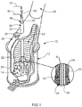
- FIG. 1 there is shown a TSL reactor or furnace 10 suitable for use in conducting a pyro-metallurgical operation, using top submerged lancing (TSL) injection with a TSL lance according to the present invention.
- the furnace 10 is shown partly cut-away to reveal its interior, as if in the course of conducting a pyro-metallurgical operation.
- the furnace 10 has a tall cylindrical base section 12 for containing a molten bath 14 comprising, or having an upper layer, of slag. Extending from the upper extent of the base section 12, the furnace 10 has an asymmetrical, frusto-conical roof 16 and, above roof 16, an off-take flue 18.
- the section 12 and roof 16 of furnace 10 typically have an outer shell 20 of steel that is lined with suitable refractory 22.
- a vertically suspended lance 24, shown in more detail in Figure 2 extends down into the base section 12 of furnace 10, through the roof 16 and close to the axis of section 12.
- the lance 24 passes through the roof portion 16 and is able to be raised or lowered by a carriage (not shown) to which the upper end of lance 24 is adapted to be connected.
- the carriage is moveable vertically on a guide structure (not shown).
- an oxygen-containing gas and a suitable fuel can be injected into the bath 14.
- the fuel may be entrained in a carrier gas, and typically is so entrained if it is a solid such as fine particulate coal.
- the fuel also may be a suitable hydrocarbon gas or liquid.
- at least part of feed material to be smelted can be charged to the furnace 10, to fall into the bath 14, via inlet port 26. Additionally or alternatively, such feed material, if in particulate fines, can be injected into the bath via an appropriate passage of lance 24. Sealing (not shown) is provided for substantially sealing around the opening in furnace portion 16 through which lance 24 passes, and at port 26. Also, furnace 10 is kept below atmospheric pressure to prevent gases from exiting from the furnace 10 other than via flue 18.
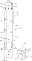
- the lance 24 shown in the axial, sectional view of Figure 2 has a concentric arrangement of an outer pipe 28 and an inner pipe 30.
- the lance 24 extends concentrically through a shroud tube 32 that terminates a substantial distance above the lower, tip end of lance 24 so that, in use of the lance, tube 32 also terminates a sufficient level above the bath 14.
- the pipes 28 and 30 may be of substantially the same length.
- the inner pipe 30 terminates above the tip end of the lance, as seen in Figure 2 , to provide a mixing and combustion chamber 34 within pipe 28, below the end of pipe 30, as required in lances in accordance with the present invention.
- Process gas that provides external cooling for the outer pipe 28 is supplied via a conduit 36 to an annular space 38 between shroud device 32 and lance 24.
- internal cooling of pipe 28 is achieved by an oxygen containing gas that is supplied via a conduit 40 for flow of the oxygen containing gas down an annular passage 42 defined between pipes 28 and 30 and communicating with chamber 34.
- Fuel can be supplied via a conduit 44 for flow into and down a passage 46 comprising the bore of pipe 30.
- Axially spaced swirlers 48 are provided in the passage between pipes 28 and 30, above the lower end of pipe 30 of lance 24.
- Each swirler 48 may be in the form of a single helical ribbon, as shown, or a system of multi-start helical ribbons. Swirling helical flow is imparted by swirlers 48 to the oxygen-containing gas passing down passage 42, and this forces the gas outwardly against the inner surface of pipe 28 and enhances cooling of pipe 28. The swirling also achieves a degree of mixing of that gas and the fuel in the mixing and combustion chamber 34.
- the swirlers 48 are mounted on the outer surface of pipe 30, such as by welding, after which pipe 28 is received as a sleeve along pipe 30 and along the swirlers 48 provided on pipe 30.
- the swirlers 48 have a width such that each has an outer helical edge closely adjacent to the inner surface of outer pips 28.
- substantially all gas passing down passage 42 is constrained to a helical flow path in passage 42 prior to entering chamber 34, and this is able to achieve a degree of mixing, in chamber 34, of the gas from passage 42 and fuel passing into chamber 34 from passage 46.
- a resultant gas/fuel mixture is fired to generate a combustion flame issuing from chamber 34 that is sufficient for the purpose of some TSL pyro-metallurgical operations.
- Not all material to comprise fuel need be combusted, as injection of some of the material into the molten bath may be required to provide a reducing agent or reductant. Where reducing agent is required in the molten bath, it is usual to designate the material as "fuel/reductant", with that part not combusted as fuel being injected within the bath and able to function as reductant.
- passage 42 and swirler device 48 may be provided between pipe 28 and an intermediate pipe that is located between pipes 28 and 30. In that arrangement, a further annular passage for particulate feed material will be defined between the intermediate pipe and pipe 30.
- the lance 24 is lowered to a position in which its lower tip end is above the initially quiescent bath 14.
- oxygen-containing gas via conduit 40 and fuel via conduit 44 are injected through the lance 24, the fuel is combusted by igniting the resultant mixture of oxygen-containing gas and fuel formed in the chamber 34 before issuing from the lower, tip-end of the lance 24.
- the materials supplied through the lance for this combustion of the fuel are supplied at a high velocity resulting in generation of a very strong combustion jet or flame that impinges on the slag surface of bath 14, thereby causing strong splashing of the slag.
- the top-submerged injection generates substantial turbulence in the slag such that splashing of the slag continues, and intimate mixing of feed material with the slag can be achieved.
- the furnace 10 then is in a condition enabling a required pyro-metallurgical process to be conducted.
- a cooling gas can be supplied via conduit 36 to the passage 38 between shroud tube 32 and outer pipe 28 of lance 24 so as to issue into a gas space 52 above the bath 14. The cooling gas further assists in cooling of the outer surface of pipe 28 of lance 24 and maintenance of the coating layer 34 of solidified slag.
- the cooling gas may be an oxygen-containing gas such as air or oxygen-enriched air to enable recovery of heat energy to the bath 14 by post-combustion of gases, such as carbon monoxide and hydrogen, evolved from bath 14 during the pyro-metallurgical operation.
- the cooling gas may be a non-oxidising gas such as nitrogen or an essentially non-oxidising, cooled process gas recovered from the flue gases.
- the lower part of the length of passage 42 is provided with a gas flow-modifying device 60.
- device 60 is disposed above chamber 34, between the outer pipe 28 and the inner pipe 30.
- the device 60 is operable to impart an inward flow component, away from the inner surface of pipe 28, to oxygen-containing gas flowing down passage 42, prior to the gas passing longitudinally into the chamber 34 and towards the lower, outlet end of lance 24.
- the device is able to enhance mixing of the gas with fuel passing into chamber 34 from passage 46 of pipe 30, relative to mixing able to be achieved solely by swirlers 48 (i.e. without device 60).
- the device 60 comprises a three-start arrangement of circumferentially spaced helical vanes 62, and a frusto-conical sleeve or cone ring 64 that extends around and seals against the outer periphery of each vane 62.
- the three vanes 62 extend longitudinally to the junction between passage 42 and the upper end of chamber 34.
- the vanes 62 in addition to extending longitudinally, also extend circumferentially around the outer surface of pipe 30, so as to be of helical form.
- Each vane 62 is of narrow strip form, and secured, such as by welding, along one of its side edges to the outer surface of pipe 34, so that its width projects from that surface.
- each of the vanes 62 narrows in width along its length from a maximum width at or nearer to its upper end. Additionally, while the vanes 62 shown are substantially flat in transverse cross-sections and perpendicular to the longitudinal axis of lance 24, as is preferred, they may be inclined or curved in such cross-sections so their upper surface faces towards that axis. However, in each arrangement for lance 24 the vanes 62, in combination with the sleeve or cone ring 64, are to assist in imparting an inward flow component, away from pipe 28, to the gas flowing through the lower part of the length of passage 42, thereby enhancing mixing of the gas with fuel received into chamber 34 from passage 46, improving fuel combustion and strengthening the flame strength. These factors also result in spacing of the flame from the inner surface of pipe 28 and thereby minimise heating of pipe 28 by the flame.
- device 60 has a solid annular cone ring 64 having a frusto-conical inner surface 66.
- surface 66 defines an annular passage 68 that decreases in radial width from a maximum at the upper end 68a to a minimum at the lower end 68b.
- the arrangement is such that ring 64, vanes 62 and pipe 30 together define a respective helical flow path of decreasing cross-section between each successive pair of vanes 62, with each flow path not only constraining the gas to helical flow paths imparting a flow component away from outer pipe 28, but also increasing the flow velocity of the gas to a maximum at lower end 68b.
- the solid cone ring 64 has a substantially cylindrical outer surface 70 that may contact or be closely adjacent to the inner surface of outer pipe 28.
- outer surface 70 of ring 64 may be spaced sufficiently from the inner surface of pipe 28 to define a narrow annular gap 72 between.
- the gap 72 preferably is sufficient to enable a minor proportion of the gas passing down passage 42 to pass between device 60 and pipe 28, thereby cooling the latter.
- gap 72 most preferably enables passage of an annular curtain of gas.
- Back pressure resulting from the decreasing cross-section of gas flow paths through device 60 acts to increase the flow velocity of gas passing through gap 72, further assisting with cooling of pipe 28.
- vanes 62 of device 60 are secured at their inner edges to pipe 30.
- cone ring 64 may be secured at its inner surface 66 to the radially-outer edges of vanes 62, such as by welding.
- ring 64 may be secured at intervals around its outer surface 70 to outer pipe 28, such as by fasteners, or by fastening straps bridging across passage 42 to locations on inner pipe 30 above device 60.
- the flow-modifying device 160 has two vanes 162 in a two-start arrangement, while device 260 of Figure 4 has eight vanes 262.
- devices 160 and 260 instead of a solid cone ring 64 as in device 60 of Figure 2 , devices 160 and 260 have a frusto-conical sleeve 164, 264. While each of sleeves 164, 264 has a frusto-conical inner surface 166, 266, the sleeves are formed of sheet metal and have a respective outer surface 170 in the case of device 160, but not shown for device 260, which is of the same form as the surface 166, 266.
- the arrangement is shown as having device 160 installed in the passage 142 between an outer pipe 128 having an inner diameter P 1 and an inner pipe 130 having an outer diameter P 2 .
- the device 160 has an overall height H 1 , with the sleeve 164 having a height H 2 , with an upper diameter D 1 and a lower diameter D 2 .
- the upper diameter D 1 of sleeve 164 is less than the inner diameter P 1 of outer pipe 128 to leave a small annular gap G 1 at the top of sleeve 164, and a relatively large annular spacing W 1 between the upper end of sleeve 164 and pipe 130.
- the frusto-conical form of sleeve 164 results in a much larger annular gap G 2 between the lower end of sleeve 164 and the inner surface of outer pipe 128 and a correspondingly lesser spacing W 2 between the lower end of sleeve 164 and the outer surface of pipe 130.
- the radial width of gap G 1 enables a minor proportion of gas passing down passage 142 to flow down over, and cool, the inner surface of pipe 128.
- the major part of the gas passes down through device 160, along flow paths between each successive pair of vanes 162.
- devices 60 of Figure 2 and device 160 of Figure 3 have multi-start arrays of vanes 62, 162, the showing of three and two vanes, respectively, is for simplicity of illustration. There preferably are at least four vanes, such as from seven to twelve.
Description
- This invention relates to top submerged injecting lances for use in molten bath pyro-metallurgical operations.
- The following discussion of the background to the invention is intended to facilitate an understanding of the invention. However, it should be appreciated that the discussion is not an acknowledgement or admission that any of the material referred to was published, known or part of the common general knowledge as at the priority date of the application.
- Molten bath smelting operations, or other pyro-metallurgical operations that require interaction between the bath and a source of oxygen-containing gas, utilize several different arrangements for the supply of the gas. In general, these operations involve direct injection into molten matte/metal. This may be by bottom blowing tuyeres as in a Bessemer type of furnace or side blowing tuyeres as in a Peirce-Smith type of converter. Alternatively, the injection of gas may be by means of a lance to provide either top blowing or submerged injection. Examples of top blowing lance injection are the KALDO and BOP steel making plants in which pure oxygen is blown from above the bath to produce steel from molten iron. Another example is the Mitsubishi copper process, in which injection lances cause jets of gas, such as air or oxygen-enriched air, to impinge on and penetrate the top surface of the bath, respectively to produce and to convert copper matte. In the case of submerged lance injection, the lower end of the lance is submerged so that injection occurs within rather than from above a slag layer of the bath, to provide top submerged lancing (TSL) injection, a well-known example of which is the Outotec Ausmelt TSL technology that is applied to a wide range of metals processing.
- With both forms of injection from above, that is, with both top blowing and TSL injection, the lance is subjected to intense prevailing bath temperatures. The top blowing in the Mitsubishi copper process uses a number of relatively small steel lances which have an inner pipe of about 50 mm diameter and an outer pipe of about 100 mm diameter. The inner pipe terminates at about the level of the furnace roof, well above the reaction zone. The outer pipe, which is rotatable to prevent it sticking to a water-cooled collar at the furnace roof, extends down into the gas space of the furnace to position its lower end about 500-800 mm above the upper surface of the molten bath. Particulate feed entrained in air is blown through the inner pipe, while oxygen enriched air is blown through the annulus between the pipes. Despite the spacing of the lower end of the outer pipe above the bath surface, and any cooling of the lance by the gases passing through it, the outer pipe burns back by about 400 mm per day. The outer pipe therefore is slowly lowered during an operation to offset this burn back and, when required, new sections are attached to the top of the outer, consumable pipe.
- The lances for TSL injection are much larger than those for top blowing, such as in the Mitsubishi process described above. A TSL lance usually has at least an inner and an outer pipe, as assumed in the following, but may have at least one other pipe concentric with the inner and outer pipes. Typical large-scale TSL lances have an outer pipe diameter of 200 to 500 mm, or larger. Also, the lance is much longer and extends down through the roof of a TSL reactor, which may be about 10 to 15 m tall, so that the lower end of the outer pipe is immersed to a depth of about 300 mm or more in a molten slag phase of the bath, but is protected by a coating of solidified slag formed and maintained on the outer surface of the outer pipe by the cooling action of the injected gas flow within. The inner pipe may terminate at about the same level as the outer pipe, or at a higher level of up to about 1000 mm above the lower end of the outer pipe. Thus, it can be the case that the lower end of only the outer pipe is submerged. In any event, a helical vane or other flow-shaping device may be mounted on the outer surface of the inner pipe to span the annular space between the inner and outer pipes. The vanes impart a strong swirling action to an air or oxygen-enriched blast along that annulus and serve to enhance the cooling effect as well as ensure that gas is mixed well with fuel and feed material supplied through the inner pipe with the mixing occurring substantially in a mixing chamber defined by the outer pipe, below the lower end of the inner pipe where the inner pipe terminates a sufficient distance above the lower end of the outer pipe.
- The outer pipe of the TSL lance wears and burns back at its lower end, but at a rate that is considerably reduced by the protective frozen slag coating than would be the case without the coating. However, this is controlled to a substantial degree by the mode of operation with TSL technology. The mode of operation makes the technology viable despite the lower end of the lance being submerged in the highly reactive and corrosive environment of the molten slag bath. The inner pipe of a TSL lance may be used to supply feed materials, such as concentrate, fluxes and reductant to be injected into a slag layer of the bath, or it may be used for fuel. An oxygen containing gas, such as air or oxygen enriched air, is supplied through the annulus between the pipes. Prior to submerged injection within the slag layer of the bath being commenced, the lance is positioned with its lower end, that is, the lower end of the outer pipe, spaced a suitable distance above the slag surface. Oxygen-containing gas and fuel, such as fuel oil, fine coal or hydrocarbon gas, are supplied to the lance and a resultant oxygen/fuel mixture is fired to generate a flame jet that impinges onto the slag. This causes the slag to splash to form, on the outer lance pipe, a coating of liquid slag that is solidified by the gas stream passing through the lance to provide the solid slag coating mentioned above. When the lance then lowered to achieve injection within the slag, the ongoing passage of oxygen-containing gas through the lance maintains the lower extent of the lance at a temperature at which the solidified slag coating is maintained and protects the outer pipe.
- With a new TSL lance, the relative positions of the lower ends of the outer and inner pipes, that is, the distance the lower end of the inner pipe is set back, if at all, from the lower end of the outer pipe, is an optimum length for a particular pyro-metallurgical operating window determined during the design. The optimum length can be different for different uses of TSL technology. Thus, in a two stage batch operation for converting copper matte to blister copper with oxygen transfer through slag to matte, a continuous single stage operation for converting copper matte to blister copper, a process for reduction of a lead containing slag, or a process for the smelting an iron oxide feed material for the production of pig iron, all have different respective optimum mixing chamber length. However, in each case, the length of the mixing chamber progressively falls below the optimum for the pyro-metallurgical operation as the lower end of the outer pipe slowly wears and burns back. Similarly, if there is zero offset between the ends of the outer and inner pipes, the lower end of the inner pipe can become exposed to the slag, with it also being worn and subjected to burn back. Thus, at intervals, the lower end of at least the outer pipe needs to be cut to provide a clean edge to which is welded a length of pipe of the appropriate diameter, to reestablish the optimum relative positions of the pipe lower ends to optimize smelting conditions.
- The rate at which the lower end of the outer pipe wears and burns back varies with the molten bath pyro-metallurgical operation being conducted. Factors that determine the rate include feed processing rate, operating temperature, bath fluidity and chemistry, lance flows rates, etc. In some cases the rate of corrosion wear and burn back is relatively high and can be such that in the worst instance several hours operating time can be lost in a day due to the need to interrupt processing to remove a worn lance from operation and replace it with another, whilst the worn lance taken from service is repaired. Such stoppages may occur several times in a day with each stoppage adding to non-processing time. While TSL technology offers significant benefits, including cost savings, over other technologies, any lost operating time for the replacement of lances carries a significant cost penalty.
- There have been proposals for fluid cooling of top blowing and TSL lances to protect them from the high temperatures encountered in pyro-metallurgical processes. Examples of fluid cooled lances for top blowing are disclosed in US patents:
-
3,223,398 to Bertram et al , -
3,269,829 to Belkin , -
3,321,139 to De Saint Martin , -
3,338,570 to Zimmer , -
3,411,716 to Stephan et al , -
3,488,044 to Shepherd , -
3,730,505 to Ramacciotti et al -
3,802,681 to Pfeifer , -
3,828,850 to McMinn et al , -
3,876,190 to Johnstone et al , -
3,889,933 to Jaquay , -
4,097,030 to Desaar , -
4,396,182 to Schaffar et al , -
4,541,617 to Okane et al ; and -
6,565,800 to Dunne . - All of these references, with the exception of
3,223,398 to Bertram et al and3,269,829 to Belkin , utilise concentric outermost pipes arranged to enable fluid flow to the outlet tip of the lance along a supply passage and back from the tip along a return passage, although Bertram et al use a variant in which such flow is limited to a nozzle portion of the lance. While Belkin provides cooling water, this passes through outlets along the length of an inner pipe to mix with oxygen supplied along an annular passage between the inner pipe and outer pipe, so as to be injected as steam with the oxygen. Heating and evaporation of the water provides cooling of the lance of Belkin, while stream generated and injected is said to return heat to the bath. -
US patents 3,521,872 to Themelis ,4,023,676 to Bennett et al and4,326,701 to Hayden, Jr. et al purport to disclose lances for submerged injection. The proposal of Themelis is similar to that ofUS 3,269,829 to Belkin . Each uses a lance cooled by adding water to the gas flow and relying on evaporation into the injected stream, an arrangement that is not the same as cooling the lance with water through heat transfer in a closed system. However, the arrangement of Themelis does not have an inner pipe and the gas and water are supplied along a single pipe in which the water is vaporized. The proposal of Bennett et al, while referred to as a lance, is more akin to a tuyere in that it injects, below the surface of molten ferrous metal, through the peripheral wall of a furnace in which the molten metal is contained. In the proposal of Bennett et al, concentric pipes for injection extend within a ceramic sleeve while cooling water is circulated through pipes encased in the ceramic. In the case of Hayden, Jr. et al, provision for a cooling fluid is made only in an upper extent of the lance, while the lower extent to the submergible outlet end comprises a single pipe encased in refractory cement. - Limitations of the prior art proposals are highlighted by Themelis. The discussion is in relation to the refining of copper by oxygen injection. While copper has a melting point of about 1085°C, it is pointed out by Themelis that refining is conducted at a superheated temperature of about 1140°C to 1195°C. At such temperatures lances of the best stainless or alloy steels have very little strength. Thus, even top blowing lances typically utilize circulated fluid cooling or, in the case of the submerged lances of Bennett and Hayden, Jr, et al, a refractory or ceramic coating. The advance of
US 3,269,829 to Belkin , and the improvement over Belkin provided by Themelis, is to utilize the powerful cooling able to be achieved by evaporation of water mixed within the injected gas. In each case, evaporation is to be achieved within, and to cool, the lance. The improvement of Themelis over Belkin is in atomization of the coolant water prior to its supply to the lance, avoiding the risks of structural failure of the lance and of an explosion caused by injection of liquid water within the molten metal. -
US patent 6,565,800 to Dunne discloses a solids injection lance for injecting solid particulate material into molten material, using an unreactive carrier. That is, the lance is simply for use in conveying the particulate material into the melt, rather than as a device enabling mixing of materials and combustion. The lance has a central core tube through which the particulate material is blown and, in direct thermal contact with the outer surface of the core tube, a double-walled jacket through which coolant such as water can be circulated. The jacket extends along a part of the length of the core tube to leave a projecting length of the core tube at the outlet end of the lance. The lance has a length of at least 1.5 metres and from the realistic drawings, it is apparent that the outside diameter of the jacket is of the order of about 12 cm, with the internal diameter of the core tube of the order of about 4 cm. The jacket comprises successive lengths welded together, with the main lengths of steel and the end section nearer to the outlet end of the lance being of copper or a copper alloy. The projecting outlet end of the inner pipe is of stainless steel which, to facilitate replacement, is connected to the main length of the inner pipe by a screw thread engagement. - The lance of
US6,565,800 to Dunne is said to be suitable for use in the HiSmelt process for production of molten ferrous metal, with the lance enabling the injection of iron oxide feed material and carbonaceous reductant. In this context, the lance is exposed to hostile conditions, including operating temperatures of the order of 1400°C. However, as indicated above with reference to Themelis, copper has a melting point of about 1085°C and even at temperatures of about 1140°C to 1195°C, stainless steels have very little strength. Perhaps the proposal of Dunne is suitable for use in the context of the HiSmelt process, given the high ratio of about 8:1 in cooling jacket cross-section to the cross-section of the core tube, and the small overall cross-sections involved. The lance of Dunne is not a TSL lance, nor is it suitable for use in TSL technology. - Examples of lances for use in pyro-metallurgical processes based on TSL technology are provided by
US patent 4,251,271 and5,251,879 , both to Floyd andUS patent 5,308,043 to Floyd et al. As detailed above, slag initially is splashed by using the lance for top blowing top blowing onto a molten slag layer, to achieve a protective coating of slag on the lance that is solidified by high velocity top blown gas that generates the splashing. The solid slag coating is maintained despite the lance then being lowered to submerge the lower outlet end in the slag layer to enable the required top submerged lancing injection within the slag. The lances ofUS patent 4,251,271 and5,251,879 , both to Floyd, operate in this way with the cooling to maintain the solid slag layer being solely by injected gas in the case ofUS patent 4,251,271 and by that gas plus gas blown through a shroud pipe in the case ofUS patent 5,251,879 . However, withUS patent 5,308,043 to Floyd et al cooling, additional to that provided by injected gas and gas blown through a shroud pipe, is provided by cooling fluid circulated through annular passages defined by the outer three pipes of the lance. This is made possible by provision of an annular tip of solid alloy steel that, at the outlet end of the lance, joins the outermost and innermost of those three pipes around the circumference of the lance. The annular tip is cooled by injected gas and also by coolant fluid that flows across an upper end face of the tip. The solid form of the annular tip, and its manufacture from a suitable alloy steel, result in the tip having a good level of resistance to wear and burn back. The arrangement is such that a practical operating life can be achieved with the lance before it is necessary to replace the tip in order to safeguard against a risk of failure of the lance enabling cooling fluid to discharge within the molten bath. - Top submerged lancing (TSL) injection has applied widely in pyro-metallurgical processes because of its advantages over the top-blowing lance. In pyro-metallurgical processes such as TSL smelting furnace, one of the important issues is the design of the lance. Due to the aggressive nature of high temperature slag phase in which the submerged injection is conducted, as well as the usual presence of a combustion flame generated by combustion of fuel at or within the submerged end of the lance, the operational period of the top submerged lance between tip repairs can be short. Those conditions cause wear and burn-back at the outlet end of the lance, while wear can be further exacerbated by the injection of mineral concentrate in some TSL pyro-metallurgical operations. Some typical lances for top submerged injection have been proposed in the above-mentioned
US patents 4,251,271 and5,251,879 to Floyd as well as in our pending applicationsWO2013/000017 andWO2013/029092 . Typically these lances include helical swirlers that are used to constrain the gas to a helical flow path in a upper part of the length of the lance, in order to facilitate mixing of the injected gas and fuel in a combustion zone within an outlet end section of the lance or at least partly beyond that end. - The present invention relates to an improved top submerged injecting lance for use in TSL pyro-metallurgical operations. The lance of the present invention provides an alternative choice to the lance of
US patent 5,308,043 to Floyd et al that, at least in preferred forms, can provide benefits over the lance of that patent. - The present invention provides a lance for top submerged lancing (TSL) injection in a pyro-metallurgical operation. The lance has at least two substantially concentric pipes, with an annular passage for oxygen-containing gas defined between an outermost one of the pipes and a next adjacent pipe and a further passage for fuel defined within an innermost one of the pipes. The outermost pipe has a lower part of its length, from a submergible lower outlet end of the lance, by which the outermost pipe extends beyond an outlet end of the or each other pipe to define between the outlet end of the outermost pipe and the outlet end of the or each other pipe a chamber with which the passage for oxygen-containing gas communicates. The lance further includes a gas flow-modifying device that is disposed in a lower end section of the passage for oxygen-containing gas, adjacent to the chamber, and that is operable to impart an inward flow component, away from the inner surface of the outermost pipe, to oxygen-containing gas passing into and longitudinally within the chamber towards the outlet end of the lance and thereby enhance mixing of the oxygen-containing gas with fuel passing into the chamber from the passage for fuel. The flow-modifying device has at least one inner component of helical form , and an outer component that extends around the at least one inner component, such that the flow-modifying device constrains gas flowing through to the lower end section of the annular passage to a helical flow path, of decreasing cross-section, around the outer surface of the next adjacent pipe.
- In use of the TSL lance of the invention, oxygen-containing gas is supplied under pressure to a first connector at the upper end of the lance, for flow longitudinally down the length of the annular passage for oxygen-containing gas that is defined between the outermost and next adjacent pipes. The gas may be oxygen, air or oxygen-enriched air. Also, a fuel that may be fuel oil, LPG, petroleum gas or fine
particulate fuel in a carrier gas, such as coal or other solid carbonaceous fuel entrained in air or nitrogen, is supplied under pressure to a second connector at the upper end of the lance, for flow longitudinally down the passage for fuel that is defined within the innermost pipe or a passage defined between the innermost pipe and a next adjacent pipe not being the outermost pipe. The arrangement is such that the oxygen-containing gas and the fuel are able to mix in the chamber defined between the outlet end of the outermost pipe and the outlet end of the or each other pipe, to provide a combustible mixture able to be fired or ignited to generate a strong combustion flame that extends beyond the outlet end of the lance. - As will be appreciated from earlier description on the Background to the Invention, the lance initially is suspended over a slag bath so the flame generated from the combustible mixture impinges on the slag surface to cause an external lower end section of the lance to be coated by splashed slag droplets. The slag is solidified by the cooling effect of the flow of oxygen-containing gas along and beyond the annular passage for oxygen-containing gas, to form a solidified slag coating that is able to be maintained even after the lance is lowered to submerge the lower end of the lance within the slag to enable the flame to generate a combustion zone within the slag. This procedure has been used widely in numerous different pyro-metallurgical processes, although difficulties are encountered in some operations. For example, mixing of the oxygen-containing gas and the fuel may not be sufficient to achieve efficient combustion of the fuel, resulting in difficulty in maintaining the bath temperature by the submerged combustion and dispersal of fuel within the bath in which the fuel acts, contrary to intentions, as a reducing agent. Also, particularly at bath temperatures close to the upper end of the temperature range for use in TSL technology, the required solid slag coating can be difficult to maintain and, where that coating is lost, rapid erosion of the outermost pipe occurs. At such higher temperatures, the cooling effect provided by the oxygen-containing gas can be inadequate for cooling the outermost pipe, while the combustion flame can pass too close to the inner surface of the outermost pipe and further exacerbate the difficulty in adequately cooling the outermost pipe. The flow-modifying device of the lance according to the present invention enables improved operation by facilitating mixing of the oxygen-containing gas and thereby improving the efficiency of fuel combustion, as well as acting to concentrate the combustion flame and thereby increasing the spacing of the flame from the inner surface of the outermost pipe and so assisting in maintaining the solidified slag coating.
- The lance of the invention preferably includes at least one single- or multi-start helical vane swirler in the annular passage for oxygen-containing gas.
US patent 4,251,271 to Floyd proposes use of a lance with only one swirler for oxygen containing gas extending over a major part of the length of the annular passage. However, the lance of the present invention preferably includes at least one relatively short swirler, with there more preferably being two or more such shorter swirlers which, in their preferred multi-start form, also are referred to as sets. This is in line with current practices as the use of short swirlers or sets, rather than longer swirlers as inUS 4,251,271 , results in a lower gas pressure drop between the upper and lower ends of the lance, so enabling use of a lower gas supply pressure. - The swirlers cause spinning of the oxygen containing gas injected along the annular passage. As a result the gas is forced centrifugally against the inner surface of the outermost pipe, enhancing the cooling effect provided by the gas relative to the cooling achievable without swirlers. However, this action of the swirlers is the opposite of that required for good mixing of the gas with fuel in the chamber. That is, the gas is required to move inwardly, rather than outwardly, in order to obtain efficient mixing in the chamber, and the flow-modifying device of the invention is to offset any disadvantage resulting from the action of the swirlers.
- The flow-modifying device can take a variety of forms. However, in each form, the device functions by imparting to the gas flowing longitudinally towards the chamber through the lower end section of the annular passage for oxygen-containing gas, a flow component away from the inner surface of the outermost pipe. The component may in effect be somewhat radial or radial and longitudinal but, in any event, preferably generates substantial turbulence or eddy currents in the oxygen-containing gas flowing into and within the chamber so that mixing of the gas and fuel is further enhanced.
- The flow-modifying device has at least one inner component of helical form, and an outer component that extends around the at least one inner component. The arrangement is such that the flow-modifying device constrains gas flowing through to the lower end section of the annular passage to a helical flow path, of decreasing cross-section, around the outer surface of the next innermost pipe. The or each inner component preferably is a helical vane, such that the flow-modifying device is a single-or multi-start helical arrangement. The at least one vane of the inner component may be secured at intervals, or continuously, along an inner helical edge, to the out surface of the next innermost pipe. Preferably, the at least one vane decreases in width, radially relative to the next innermost pipe, from a maximum width at or nearer to an upper end of the vane. The outer component closes the outer periphery of the helical flow path outwardly from and around the next innermost pipe. Where there is only a single inner component, the outer component may be of a helical form having a radially inner surface bridging around and between successive flights of the single vane. However, the outer component preferably bridges around and across successive flights of the or each vane. Where required to bridge across successive flights, the outer component may have a stepped or tapered radially inner surface. In a preferred form, the outer component has a frusto-conical inner surface, while its outer surface also may be frusto-conical or it may be of another form such as cylindrical or tapered cone.
- The or each vane comprising the at least one inner component has an upper helical surface that preferably faces an upper, inlet end of the lance and that, in radial sections, is substantially perpendicular to the longitudinal axis of the lance. However, other arrangements are possible in that the upper surface may be inclined, or curve, towards that axis.
- Most preferably the or each vane of the flow-modifying device is secured over, such as to, the outer surface of the next adjacent pipe. The securement may be by welding, either continuously or intermittently along the length of each vane. Alternatively, the outer component of the flow-modifying device may comprise a sleeve or annular housing, while the or each vane may be secured to the inner surface of the sleeve or housing, again by continuous or intermittent welding. The components of the flow-modifying device may be of a steel, preferably one having similar thermal expansion characteristics to the steel of which the pipes of the lance are made, and preferably such that the steels are of the same composition, or are close in composition.
- To the extent that the flow-modifying device of the lance of the invention includes at least one helical vane, there is some similarity between the device and swirlers. The swirlers are helical and may be of single- or multi-start helical form. However, the helical form is the extent of the similarity, as the swirlers and the vanes of the flow-modifying device differ significantly in overall form and in function. As a practical matter the swirlers are secured or mounted on and along the outer surface of the pipe next adjacent to the outermost pipe. Also, along their length, they have a substantially uniform width such that it substantially spans the radial width of the annular passage for oxygen-containing gas, so that the swirler device constrains substantially all of that gas to flow helically. However, while the vanes of the flow-modifying device also may be secured or mounted on and along the outer surface of the next adjacent pipe, they need only have a width that substantially spans the radial width of the annular passage at or towards their upper ends, with the vanes then decreasing in width. Also, the vanes are to co-operate with the outer component of the flow-modifying device to define a flow path of decreasing cross-section. Of course, there is the further major difference in that swirlers impart an outward flow component to the gas, rather than an inward flow component achieved by the combination of the vanes and the outer component of the flow-modifying device.
- The present invention provides a lance for top submerged injection that, due to the enhancement of gas flow into and through the mixing chamber defined in the lower part of the length outer pipe, provides improved mixing of the gas with fuel being injected, improved combustion of the mixture, and a stronger combustion flame that is concentrated away from the inner surface of the outer pipe. Also, the enhancements enable the protective layer of solidified slag to be better maintained, even at higher operating temperatures, or to be maintained over a longer operating period at a given temperature, providing a reduction in the operating cost for the pyro-metallurgical operation in which the lance is used by increasing the operating time between successive shut downs for lance replacement.
- The present invention will now be described with reference to the figures of the accompanying drawings, which illustrate particular preferred embodiments of the present invention, wherein:
-
Figure 1 is a schematic perspective view, partly broken away, depicting a top submerged lancing (TSL) injection reactor; -
Figure 2 illustrates one form of TSL lance according to the invention, suitable for use in a TSL reactor such as depicted inFigure 1 ; -
Figure 3 is an enlarged sectional view of components similar to those ofFigure 2 ; and -
Figure 4 is a top plan view of a modified form of the components shown inFigure 3 , taken on a line corresponding to line A-A ofFigure 3 . - Before directly addressing the drawings, it is pertinent to note that a TSL lance according to the invention, as with TSL lances in general, necessarily is of large dimensions. At a location remote from the outlet end, such as adjacent to an upper or inlet end, the lance has a structure by which it can be suspended so as to hang down vertically within a TSL reactor. The lance may have a length as short as about 7.5 metres, such as for a small special purpose TSL reactor. The lance may be up to about 25 metres in length, or even greater, for a special purpose large TSL reactor. More usually, the lance ranges from about 10 to 20 metres in length. These dimensions relate to the overall length of the lance and the outermost pipe through to the outlet end. The next adjacent pipe, and the innermost and any other pipe for a lance with at least three substantially concentric pipes, may extend to the outlet end and therefore be of substantially the same overall length as the outermost pipe. However, each pipe other than the outermost pipe may terminate a short distance from the outlet end of the outermost pipe by, for example, up to about 1000 mm. The lance typically has a large diameter, such as set by an internal diameter for the outermost pipe of from about 100 to 650 mm, preferably about 200 to 650 mm, and an overall diameter of from 150 to 700 mm, preferably about 250 to 550 mm.
- Turning now to
Figure 1 , there is shown a TSL reactor orfurnace 10 suitable for use in conducting a pyro-metallurgical operation, using top submerged lancing (TSL) injection with a TSL lance according to the present invention. Thefurnace 10 is shown partly cut-away to reveal its interior, as if in the course of conducting a pyro-metallurgical operation. Thefurnace 10 has a tallcylindrical base section 12 for containing amolten bath 14 comprising, or having an upper layer, of slag. Extending from the upper extent of thebase section 12, thefurnace 10 has an asymmetrical, frusto-conical roof 16 and, aboveroof 16, an off-take flue 18. Thesection 12 androof 16 offurnace 10 typically have anouter shell 20 of steel that is lined with suitable refractory 22. A vertically suspendedlance 24, shown in more detail inFigure 2 , extends down into thebase section 12 offurnace 10, through theroof 16 and close to the axis ofsection 12. Thelance 24 passes through theroof portion 16 and is able to be raised or lowered by a carriage (not shown) to which the upper end oflance 24 is adapted to be connected. The carriage is moveable vertically on a guide structure (not shown). By means oflance 24, an oxygen-containing gas and a suitable fuel can be injected into thebath 14. The fuel may be entrained in a carrier gas, and typically is so entrained if it is a solid such as fine particulate coal. However, the fuel also may be a suitable hydrocarbon gas or liquid. Also, at least part of feed material to be smelted can be charged to thefurnace 10, to fall into thebath 14, viainlet port 26. Additionally or alternatively, such feed material, if in particulate fines, can be injected into the bath via an appropriate passage oflance 24. Sealing (not shown) is provided for substantially sealing around the opening infurnace portion 16 through whichlance 24 passes, and atport 26. Also,furnace 10 is kept below atmospheric pressure to prevent gases from exiting from thefurnace 10 other than viaflue 18. - The
lance 24 shown in the axial, sectional view ofFigure 2 has a concentric arrangement of anouter pipe 28 and aninner pipe 30. Thelance 24 extends concentrically through ashroud tube 32 that terminates a substantial distance above the lower, tip end oflance 24 so that, in use of the lance,tube 32 also terminates a sufficient level above thebath 14. For some pyro-metallurgical operations, thepipes inner pipe 30 terminates above the tip end of the lance, as seen inFigure 2 , to provide a mixing andcombustion chamber 34 withinpipe 28, below the end ofpipe 30, as required in lances in accordance with the present invention. As shown by the mid-region break inpipes outer pipe 28 is supplied via aconduit 36 to anannular space 38 betweenshroud device 32 andlance 24. Also, internal cooling ofpipe 28 is achieved by an oxygen containing gas that is supplied via aconduit 40 for flow of the oxygen containing gas down anannular passage 42 defined betweenpipes chamber 34. Fuel can be supplied via aconduit 44 for flow into and down apassage 46 comprising the bore ofpipe 30. - Axially spaced swirlers 48 are provided in the passage between
pipes pipe 30 oflance 24. Eachswirler 48 may be in the form of a single helical ribbon, as shown, or a system of multi-start helical ribbons. Swirling helical flow is imparted byswirlers 48 to the oxygen-containing gas passing downpassage 42, and this forces the gas outwardly against the inner surface ofpipe 28 and enhances cooling ofpipe 28. The swirling also achieves a degree of mixing of that gas and the fuel in the mixing andcombustion chamber 34. Theswirlers 48 are mounted on the outer surface ofpipe 30, such as by welding, after whichpipe 28 is received as a sleeve alongpipe 30 and along theswirlers 48 provided onpipe 30. Theswirlers 48 have a width such that each has an outer helical edge closely adjacent to the inner surface ofouter pips 28. Thus, substantially all gas passing downpassage 42 is constrained to a helical flow path inpassage 42 prior to enteringchamber 34, and this is able to achieve a degree of mixing, inchamber 34, of the gas frompassage 42 and fuel passing intochamber 34 frompassage 46. A resultant gas/fuel mixture is fired to generate a combustion flame issuing fromchamber 34 that is sufficient for the purpose of some TSL pyro-metallurgical operations. Not all material to comprise fuel need be combusted, as injection of some of the material into the molten bath may be required to provide a reducing agent or reductant. Where reducing agent is required in the molten bath, it is usual to designate the material as "fuel/reductant", with that part not combusted as fuel being injected within the bath and able to function as reductant. - While
lance 24 has only twopipes passage 42 andswirler device 48 may be provided betweenpipe 28 and an intermediate pipe that is located betweenpipes pipe 30. - On start-up with
furnace 10, thelance 24 is lowered to a position in which its lower tip end is above the initiallyquiescent bath 14. When oxygen-containing gas viaconduit 40 and fuel viaconduit 44 are injected through thelance 24, the fuel is combusted by igniting the resultant mixture of oxygen-containing gas and fuel formed in thechamber 34 before issuing from the lower, tip-end of thelance 24. The materials supplied through the lance for this combustion of the fuel are supplied at a high velocity resulting in generation of a very strong combustion jet or flame that impinges on the slag surface ofbath 14, thereby causing strong splashing of the slag. The external surface ofpipe 28 below the lower end ofshroud tube 32 becomes covered with molten slag droplets that are solidified by the cooling effect of the gases passing downpipe 28, along and beyondpassage 42. The accumulating slag forms a protective coating layer 50 (see enlarged insert A) over the outer surface ofpipe 28. If not previously commenced, a flow of the cooling gas viaconduit 38 is started, with that gas issuing from the lower end ofshroud tube 32 to further cool thepipe 28. Thelance 24 then is lowered so that the lower, tip end is submerged in the slag, to provide submerged injection and form a combustion zone within the slag by the combustion of fuel in the submerged combustion flame. The top-submerged injection generates substantial turbulence in the slag such that splashing of the slag continues, and intimate mixing of feed material with the slag can be achieved. Thefurnace 10 then is in a condition enabling a required pyro-metallurgical process to be conducted. In the course of that process, a cooling gas can be supplied viaconduit 36 to thepassage 38 betweenshroud tube 32 andouter pipe 28 oflance 24 so as to issue into agas space 52 above thebath 14. The cooling gas further assists in cooling of the outer surface ofpipe 28 oflance 24 and maintenance of thecoating layer 34 of solidified slag. The cooling gas may be an oxygen-containing gas such as air or oxygen-enriched air to enable recovery of heat energy to thebath 14 by post-combustion of gases, such as carbon monoxide and hydrogen, evolved frombath 14 during the pyro-metallurgical operation. Alternatively, the cooling gas may be a non-oxidising gas such as nitrogen or an essentially non-oxidising, cooled process gas recovered from the flue gases. - With the
lance 24 ofFigures 1 and2 , the lower part of the length ofpassage 42 is provided with a gas flow-modifyingdevice 60. As can be seen,device 60 is disposed abovechamber 34, between theouter pipe 28 and theinner pipe 30. Thedevice 60 is operable to impart an inward flow component, away from the inner surface ofpipe 28, to oxygen-containing gas flowing downpassage 42, prior to the gas passing longitudinally into thechamber 34 and towards the lower, outlet end oflance 24. In imparting such flow component to the gas, the device is able to enhance mixing of the gas with fuel passing intochamber 34 frompassage 46 ofpipe 30, relative to mixing able to be achieved solely by swirlers 48 (i.e. without device 60). - In
Figure 2 , thedevice 60 comprises a three-start arrangement of circumferentially spacedhelical vanes 62, and a frusto-conical sleeve orcone ring 64 that extends around and seals against the outer periphery of eachvane 62. The threevanes 62 extend longitudinally to the junction betweenpassage 42 and the upper end ofchamber 34. Thevanes 62, in addition to extending longitudinally, also extend circumferentially around the outer surface ofpipe 30, so as to be of helical form. Eachvane 62 is of narrow strip form, and secured, such as by welding, along one of its side edges to the outer surface ofpipe 34, so that its width projects from that surface. While only schematically illustrated, each of thevanes 62 narrows in width along its length from a maximum width at or nearer to its upper end. Additionally, while thevanes 62 shown are substantially flat in transverse cross-sections and perpendicular to the longitudinal axis oflance 24, as is preferred, they may be inclined or curved in such cross-sections so their upper surface faces towards that axis. However, in each arrangement forlance 24 thevanes 62, in combination with the sleeve orcone ring 64, are to assist in imparting an inward flow component, away frompipe 28, to the gas flowing through the lower part of the length ofpassage 42, thereby enhancing mixing of the gas with fuel received intochamber 34 frompassage 46, improving fuel combustion and strengthening the flame strength. These factors also result in spacing of the flame from the inner surface ofpipe 28 and thereby minimise heating ofpipe 28 by the flame. - In the arrangement of
Figure 2 ,device 60 has a solidannular cone ring 64 having a frusto-conicalinner surface 66. Withinner pipe 30,surface 66 defines anannular passage 68 that decreases in radial width from a maximum at theupper end 68a to a minimum at thelower end 68b. The arrangement is such thatring 64,vanes 62 andpipe 30 together define a respective helical flow path of decreasing cross-section between each successive pair ofvanes 62, with each flow path not only constraining the gas to helical flow paths imparting a flow component away fromouter pipe 28, but also increasing the flow velocity of the gas to a maximum atlower end 68b. - In the arrangement of
Figure 2 , thesolid cone ring 64 has a substantially cylindrical outer surface 70 that may contact or be closely adjacent to the inner surface ofouter pipe 28. However, as shown in the enlarged insert B inFigure 2 , outer surface 70 ofring 64 may be spaced sufficiently from the inner surface ofpipe 28 to define a narrowannular gap 72 between. Thegap 72 preferably is sufficient to enable a minor proportion of the gas passing downpassage 42 to pass betweendevice 60 andpipe 28, thereby cooling the latter. For substantial uniformity of cooling ofpipe 28,gap 72 most preferably enables passage of an annular curtain of gas. Back pressure resulting from the decreasing cross-section of gas flow paths throughdevice 60 acts to increase the flow velocity of gas passing throughgap 72, further assisting with cooling ofpipe 28. - As indicated, the
vanes 62 ofdevice 60 are secured at their inner edges topipe 30. Also,cone ring 64 may be secured at itsinner surface 66 to the radially-outer edges ofvanes 62, such as by welding. Alternatively, or additionally,ring 64 may be secured at intervals around its outer surface 70 toouter pipe 28, such as by fasteners, or by fastening straps bridging acrosspassage 42 to locations oninner pipe 30 abovedevice 60. - In the similar arrangements of
Figures 3 and 4 , parts corresponding to those ofFigure 2 have the same reference numeral, plus 100 and 200, respectively. InFigure 3 , the flow-modifyingdevice 160 has twovanes 162 in a two-start arrangement, whiledevice 260 ofFigure 4 has eightvanes 262. Also, instead of asolid cone ring 64 as indevice 60 ofFigure 2 ,devices conical sleeve sleeves inner surface device 160, but not shown fordevice 260, which is of the same form as thesurface - In the
device 160 ofFigure 3 , the arrangement is shown as havingdevice 160 installed in thepassage 142 between anouter pipe 128 having an inner diameter P1 and aninner pipe 130 having an outer diameter P2. Thedevice 160 has an overall height H1, with thesleeve 164 having a height H2, with an upper diameter D1 and a lower diameter D2. The upper diameter D1 ofsleeve 164 is less than the inner diameter P1 ofouter pipe 128 to leave a small annular gap G1 at the top ofsleeve 164, and a relatively large annular spacing W1 between the upper end ofsleeve 164 andpipe 130. The frusto-conical form ofsleeve 164 results in a much larger annular gap G2 between the lower end ofsleeve 164 and the inner surface ofouter pipe 128 and a correspondingly lesser spacing W2 between the lower end ofsleeve 164 and the outer surface ofpipe 130. The radial width of gap G1 enables a minor proportion of gas passing downpassage 142 to flow down over, and cool, the inner surface ofpipe 128. The major part of the gas passes down throughdevice 160, along flow paths between each successive pair ofvanes 162. However, the downward tapering of the components ofdevice 160 results in those flow paths decreasing in cross-section to the lower, outlet end ofdevice 160, so gas flowing intochamber 134 issues at an increased flow velocity and directed towards the axis of lance 124, below the lower, outlet end ofinner pipe 130. As a result, efficient, substantially complete, mixing is achieved between the gas entering thechamber 134 frompassage 142 anddevice 160 andfuel entering chamber 134 frompipe 130. This enhanced mixing enables more efficient, substantially complete combustion of the fuel when the mixture is fired, generating a strong combustion flame that is localised belowpipe 130 and laterally spaced from the surface ofpipe 128. - While
devices 60 ofFigure 2 anddevice 160 ofFigure 3 have multi-start arrays ofvanes - Those skilled in the art will appreciate that the invention described herein is susceptible to variations and modifications other than those specifically described. It is understood that the invention includes all such variations and modifications which fall within the spirit and scope.
- Throughout the description and claims of the specification the word "comprise" and variation of the word, such as "comprising" and "comprises", is not intended to exclude other additives, components, integers or steps.
Claims (12)
- A lance for top submerged lancing (TSL) injection in a pyro-metallurgical operation, wherein
the lance has at least two substantially concentric pipes, with an annular passage for oxygen-containing gas defined between an outermost one of the pipes and a next adjacent pipe and a further passage for fuel defined within an innermost one of the pipes; the outermost pipe has a lower part of its length, from a submergible lower outlet end of the lance, by which the outermost pipe extends beyond an outlet end of the or each other pipe to define between the outlet end of the outermost pipe and the outlet end of the or each other pipe a chamber with which the passage for oxygen-containing gas communicates; and
the lance further includes a gas flow-modifying device that is disposed in a lower end section of the passage for oxygen-containing gas, adjacent to the chamber, and that is operable to impart an inward flow component, away from the inner surface of the outermost pipe, to oxygen-containing gas passing into and longitudinally within the chamber towards the outlet end of the lance and thereby enhance mixing of the oxygen-containing gas with fuel passing into the chamber from the passage for fuel, the flow-modifying device having at least one inner component of helical form , and an outer component that extends around the at least one inner component, such that the flow-modifying device constrains gas flowing through to the lower end section of the annular passage to a helical flow path, of decreasing cross-section, around the outer surface of the next adjacent pipe. - The lance of claim 1, wherein the flow-modifying device functions by imparting to the gas flowing longitudinally towards the chamber through the lower end section of the annular passage for oxygen-containing gas, a flow component away from the inner surface of the outermost pipe that in effect is somewhat radial or radial and longitudinal.
- The lance of claim 1 or 2, wherein the or each inner component is a helical vane, such that the flow-modifying device is a single or multi-start helical arrangement.
- The lance of claim 1 or 2, wherein the at least one vane of the inner component is secured at intervals, or continuously, along an inner helical edge, to the outer surface of the next innermost pipe.
- The lance of claim 1, 2, 3 or 4, wherein the at least one vane decreases in width, radially relative to the next innermost pipe, from a maximum width at or nearer to an upper end of the vane.
- The lance of any one of claims1 to 4, wherein the outer component closes the outer periphery of the helical flow path outwardly from and around the next innermost pipe.
- The lance of claim 6, wherein the outer component bridges around and across successive flights of the or each vane.
- The lance of claim 7, wherein the outer component has a frusto-conical inner surface, while its outer surface also is frusto-conical or of another form such as cylindrical.
- The lance of any one of claims 1 to 8, wherein the or each vane of the flow-modifying device is secured over, such as to, the outer surface of the next adjacent pipe, such as by welding, either continuously or intermittently, along the length of each vane.
- The lance of any one of claims 1 to 8, wherein the outer component of the flow-modifying device may comprise a sleeve or annular housing, and the or each vane is secured to the inner surface of the sleeve or housing such as by continuous or intermittent welding.
- The lance of any one of claims 1 to 10, wherein the flow-modifying device includes at least four vanes, such as from seven to twelve vanes.
- The lance of any one of claims 1 to 11, wherein the flow-modifying device is adapted to impart an inward flow component to a major proportion of gas flowing down the annular passage for oxygen-containing gas, but defines with the outermost pipe an annular gap through which a minor proportion of the gas is able to pass for flow over the inner surface of the outermost pipe.
Priority Applications (1)
| Application Number | Priority Date | Filing Date | Title |
|---|---|---|---|
| PL14795672T PL3058109T3 (en) | 2013-10-16 | 2014-10-13 | Top submerged injection lance for enhanced submerged combustion |
Applications Claiming Priority (2)
| Application Number | Priority Date | Filing Date | Title |
|---|---|---|---|
| AU2013903979A AU2013903979A0 (en) | 2013-10-16 | Top submerged injection lance for enhanced submerged combustion | |
| PCT/IB2014/065249 WO2015056143A1 (en) | 2013-10-16 | 2014-10-13 | Top submerged injection lance for enhanced submerged combustion |
Publications (2)
| Publication Number | Publication Date |
|---|---|
| EP3058109A1 EP3058109A1 (en) | 2016-08-24 |
| EP3058109B1 true EP3058109B1 (en) | 2017-03-22 |
Family
ID=51868269
Family Applications (1)
| Application Number | Title | Priority Date | Filing Date |
|---|---|---|---|
| EP14795672.6A Active EP3058109B1 (en) | 2013-10-16 | 2014-10-13 | Top submerged injection lance for enhanced submerged combustion |
Country Status (11)
| Country | Link |
|---|---|
| US (1) | US10077940B2 (en) |
| EP (1) | EP3058109B1 (en) |
| KR (1) | KR101700078B1 (en) |
| CN (1) | CN105612263B (en) |
| AU (1) | AU2014335829B2 (en) |
| CL (1) | CL2016000821A1 (en) |
| EA (1) | EA030272B1 (en) |
| ES (1) | ES2626828T3 (en) |
| PL (1) | PL3058109T3 (en) |
| WO (1) | WO2015056143A1 (en) |
| ZA (1) | ZA201602244B (en) |
Families Citing this family (5)
| Publication number | Priority date | Publication date | Assignee | Title |
|---|---|---|---|---|
| AU2013204818B2 (en) * | 2013-04-12 | 2015-02-19 | Metso Metals Oy | Molten bath temperature measurement for a top submerged lance injection installation |
| PE20181809A1 (en) * | 2015-12-09 | 2018-11-21 | Tenova South Africa Pty Ltd | METHOD OF OPERATING A TOP SUBMERGED LANCE OVEN |
| WO2017195105A1 (en) | 2016-05-10 | 2017-11-16 | Tenova South Africa (Pty) Ltd | Lance for use in a top submerged lance furnace |
| CN107043860A (en) * | 2017-05-19 | 2017-08-15 | 中国恩菲工程技术有限公司 | BOTTOM OXYGEN gun platform |
| CN112226585A (en) * | 2020-09-17 | 2021-01-15 | 孙红秀 | Steel rail welding seam heating device |
Family Cites Families (27)
| Publication number | Priority date | Publication date | Assignee | Title |
|---|---|---|---|---|
| US3240481A (en) | 1961-07-27 | 1966-03-15 | United States Steel Corp | Apparatus for adding solids and oxygen to an open hearth furnace |
| US3223398A (en) | 1963-02-20 | 1965-12-14 | Kaiser Ind Corp | Lance for use in a basic oxygen conversion process |
| US3269829A (en) | 1963-09-24 | 1966-08-30 | United States Steel Corp | Method and apparatus for introducing steam and oxygen into a bath of molten steel |
| BE648779A (en) | 1963-10-23 | 1964-10-01 | ||
| FR84791E (en) * | 1963-11-25 | 1965-04-16 | Siderurgie Fse Inst Rech | Adjustable insufflation lance for fine particles in suspension |
| US3397878A (en) * | 1965-11-19 | 1968-08-20 | Union Carbide Corp | Under-bath tuyere |
| GB1130845A (en) | 1966-04-13 | 1968-10-16 | Noranda Mines Ltd | Method and apparatus for controlling the temperature of metal lances in molten baths |
| US3411716A (en) | 1966-05-11 | 1968-11-19 | United States Steel Corp | Oxygen lance for steelmaking furnaces |
| US3488044A (en) | 1967-05-01 | 1970-01-06 | Nat Steel Corp | Apparatus for refining metal |
| US3876190A (en) | 1969-06-25 | 1975-04-08 | Commw Ind Gases | Method and apparatus for feeding particulate materials to furnaces and the like |
| US3730505A (en) | 1970-07-01 | 1973-05-01 | Centro Speriment Metallurg | Double delivery lance for refining the steel in the converter processes |
| FR2131674A5 (en) | 1971-04-10 | 1972-11-10 | Messer Griesheim Gmbh | |
| US3828850A (en) | 1973-07-12 | 1974-08-13 | Black Sivalls & Bryson Inc | High temperature material introduction apparatus |
| US3889933A (en) | 1974-02-28 | 1975-06-17 | Int Nickel Canada | Metallurgical lance |
| BE849582R (en) | 1976-01-07 | 1977-04-15 | Rene Desaar | POCKET CAST IRON DESULFURATION LANCE |
| US4023676A (en) | 1976-09-20 | 1977-05-17 | Armco Steel Corporation | Lance structure and method for oxygen refining of molten metal |
| GB1599366A (en) | 1977-05-09 | 1981-09-30 | Commw Scient Ind Res Org | Submerged injection of gas into liquid pyro-metallurgical bath |
| FR2432552A1 (en) * | 1978-08-03 | 1980-02-29 | Siderurgie Fse Inst Rech | Immersion lance consisting of two concentric tubes - esp. for injecting powder into molten iron or steel and using two tubes with the same outlet bore dia. |
| US4326701A (en) | 1979-09-29 | 1982-04-27 | Kaiser Steel Corporation | Lance apparatus |
| FR2496699B1 (en) | 1980-12-22 | 1985-06-21 | Siderurgie Fse Inst Rech | BLOWING NOZZLE FOR OXIDIZING GAS, ESPECIALLY OXYGEN, FOR THE TREATMENT OF FUSED METALS |
| JPS58185707A (en) | 1982-04-23 | 1983-10-29 | Sumitomo Metal Ind Ltd | Refining method of steel |
| SG45386A1 (en) | 1989-09-29 | 1998-01-16 | Ausmelt Ltd | Top submerged injection with a shrouded lance |
| IN181041B (en) | 1991-09-20 | 1998-04-18 | Ausmelt Ltd | |
| AUPQ783100A0 (en) | 2000-05-30 | 2000-06-22 | Technological Resources Pty Limited | Apparatus for injecting solid particulate material into a vessel |
| US9528766B2 (en) | 2011-06-30 | 2016-12-27 | Outotec Oyj | Top submerged injecting lances |
| PL2751297T3 (en) | 2011-09-02 | 2017-07-31 | Outotec Oyj | Lances for top submerged injection |
| EA025696B1 (en) * | 2011-11-30 | 2017-01-30 | Ототек Оюй | Fluid cooled lance for top submerged injection |
-
2014
- 2014-10-13 EP EP14795672.6A patent/EP3058109B1/en active Active
- 2014-10-13 PL PL14795672T patent/PL3058109T3/en unknown
- 2014-10-13 CN CN201480055842.5A patent/CN105612263B/en active Active
- 2014-10-13 WO PCT/IB2014/065249 patent/WO2015056143A1/en active Application Filing
- 2014-10-13 EA EA201690484A patent/EA030272B1/en not_active IP Right Cessation
- 2014-10-13 AU AU2014335829A patent/AU2014335829B2/en active Active
- 2014-10-13 ES ES14795672.6T patent/ES2626828T3/en active Active
- 2014-10-13 US US15/028,624 patent/US10077940B2/en active Active
- 2014-10-13 KR KR1020167009313A patent/KR101700078B1/en active IP Right Grant
-
2016
- 2016-04-05 ZA ZA2016/02244A patent/ZA201602244B/en unknown
- 2016-04-08 CL CL2016000821A patent/CL2016000821A1/en unknown
Non-Patent Citations (1)
| Title |
|---|
| None * |
Also Published As
| Publication number | Publication date |
|---|---|
| CN105612263A (en) | 2016-05-25 |
| CN105612263B (en) | 2019-02-19 |
| ES2626828T3 (en) | 2017-07-26 |
| ZA201602244B (en) | 2017-05-31 |
| CL2016000821A1 (en) | 2016-10-07 |
| KR101700078B1 (en) | 2017-01-26 |
| WO2015056143A1 (en) | 2015-04-23 |
| KR20160047583A (en) | 2016-05-02 |
| US10077940B2 (en) | 2018-09-18 |
| PL3058109T3 (en) | 2017-08-31 |
| EA201690484A1 (en) | 2016-09-30 |
| EA030272B1 (en) | 2018-07-31 |
| US20160265848A1 (en) | 2016-09-15 |
| EP3058109A1 (en) | 2016-08-24 |
| AU2014335829B2 (en) | 2016-12-15 |
Similar Documents
| Publication | Publication Date | Title |
|---|---|---|
| EP2786083B1 (en) | Fluid cooled lances for top submerged injection | |
| EP2726803B1 (en) | Top submerged injecting lances | |
| EP2751297B1 (en) | Lances for top submerged injection | |
| EP3058109B1 (en) | Top submerged injection lance for enhanced submerged combustion | |
| AU2014335829A1 (en) | Top submerged injection lance for enhanced submerged combustion | |
| CN112239798B (en) | Tuyere for basic oxygen converter | |
| WO2015056142A1 (en) | Top submerged injection lance for enhanced heat transfer | |
| NZ624378B2 (en) | Fluid cooled lances for top submerged injection |
Legal Events
| Date | Code | Title | Description |
|---|---|---|---|
| PUAI | Public reference made under article 153(3) epc to a published international application that has entered the european phase |
Free format text: ORIGINAL CODE: 0009012 |
|
| 17P | Request for examination filed |
Effective date: 20160429 |
|
| AK | Designated contracting states |
Kind code of ref document: A1 Designated state(s): AL AT BE BG CH CY CZ DE DK EE ES FI FR GB GR HR HU IE IS IT LI LT LU LV MC MK MT NL NO PL PT RO RS SE SI SK SM TR |
|
| AX | Request for extension of the european patent |
Extension state: BA ME |
|
| GRAP | Despatch of communication of intention to grant a patent |
Free format text: ORIGINAL CODE: EPIDOSNIGR1 |
|
| STAA | Information on the status of an ep patent application or granted ep patent |
Free format text: STATUS: GRANT OF PATENT IS INTENDED |
|
| DAX | Request for extension of the european patent (deleted) | ||
| INTG | Intention to grant announced |
Effective date: 20161111 |
|
| GRAS | Grant fee paid |
Free format text: ORIGINAL CODE: EPIDOSNIGR3 |
|
| GRAA | (expected) grant |
Free format text: ORIGINAL CODE: 0009210 |
|
| STAA | Information on the status of an ep patent application or granted ep patent |
Free format text: STATUS: THE PATENT HAS BEEN GRANTED |
|
| AK | Designated contracting states |
Kind code of ref document: B1 Designated state(s): AL AT BE BG CH CY CZ DE DK EE ES FI FR GB GR HR HU IE IS IT LI LT LU LV MC MK MT NL NO PL PT RO RS SE SI SK SM TR |
|
| REG | Reference to a national code |
Ref country code: GB Ref legal event code: FG4D |
|
| REG | Reference to a national code |
Ref country code: CH Ref legal event code: EP |
|
| REG | Reference to a national code |
Ref country code: AT Ref legal event code: REF Ref document number: 877836 Country of ref document: AT Kind code of ref document: T Effective date: 20170415 |
|
| REG | Reference to a national code |
Ref country code: IE Ref legal event code: FG4D |
|
| REG | Reference to a national code |
Ref country code: DE Ref legal event code: R096 Ref document number: 602014007957 Country of ref document: DE |
|
| REG | Reference to a national code |
Ref country code: SE Ref legal event code: TRGR |
|
| REG | Reference to a national code |
Ref country code: ES Ref legal event code: FG2A Ref document number: 2626828 Country of ref document: ES Kind code of ref document: T3 Effective date: 20170726 Ref country code: NL Ref legal event code: MP Effective date: 20170322 |
|
| PG25 | Lapsed in a contracting state [announced via postgrant information from national office to epo] |
Ref country code: HR Free format text: LAPSE BECAUSE OF FAILURE TO SUBMIT A TRANSLATION OF THE DESCRIPTION OR TO PAY THE FEE WITHIN THE PRESCRIBED TIME-LIMIT Effective date: 20170322 Ref country code: GR Free format text: LAPSE BECAUSE OF FAILURE TO SUBMIT A TRANSLATION OF THE DESCRIPTION OR TO PAY THE FEE WITHIN THE PRESCRIBED TIME-LIMIT Effective date: 20170623 Ref country code: NO Free format text: LAPSE BECAUSE OF FAILURE TO SUBMIT A TRANSLATION OF THE DESCRIPTION OR TO PAY THE FEE WITHIN THE PRESCRIBED TIME-LIMIT Effective date: 20170622 Ref country code: LT Free format text: LAPSE BECAUSE OF FAILURE TO SUBMIT A TRANSLATION OF THE DESCRIPTION OR TO PAY THE FEE WITHIN THE PRESCRIBED TIME-LIMIT Effective date: 20170322 Ref country code: FI Free format text: LAPSE BECAUSE OF FAILURE TO SUBMIT A TRANSLATION OF THE DESCRIPTION OR TO PAY THE FEE WITHIN THE PRESCRIBED TIME-LIMIT Effective date: 20170322 |
|
| REG | Reference to a national code |
Ref country code: LT Ref legal event code: MG4D |
|
| PG25 | Lapsed in a contracting state [announced via postgrant information from national office to epo] |
Ref country code: RS Free format text: LAPSE BECAUSE OF FAILURE TO SUBMIT A TRANSLATION OF THE DESCRIPTION OR TO PAY THE FEE WITHIN THE PRESCRIBED TIME-LIMIT Effective date: 20170322 Ref country code: LV Free format text: LAPSE BECAUSE OF FAILURE TO SUBMIT A TRANSLATION OF THE DESCRIPTION OR TO PAY THE FEE WITHIN THE PRESCRIBED TIME-LIMIT Effective date: 20170322 |
|
| PG25 | Lapsed in a contracting state [announced via postgrant information from national office to epo] |
Ref country code: NL Free format text: LAPSE BECAUSE OF FAILURE TO SUBMIT A TRANSLATION OF THE DESCRIPTION OR TO PAY THE FEE WITHIN THE PRESCRIBED TIME-LIMIT Effective date: 20170322 |
|
| REG | Reference to a national code |
Ref country code: FR Ref legal event code: PLFP Year of fee payment: 4 |
|
| PG25 | Lapsed in a contracting state [announced via postgrant information from national office to epo] |
Ref country code: RO Free format text: LAPSE BECAUSE OF FAILURE TO SUBMIT A TRANSLATION OF THE DESCRIPTION OR TO PAY THE FEE WITHIN THE PRESCRIBED TIME-LIMIT Effective date: 20170322 Ref country code: EE Free format text: LAPSE BECAUSE OF FAILURE TO SUBMIT A TRANSLATION OF THE DESCRIPTION OR TO PAY THE FEE WITHIN THE PRESCRIBED TIME-LIMIT Effective date: 20170322 Ref country code: IT Free format text: LAPSE BECAUSE OF FAILURE TO SUBMIT A TRANSLATION OF THE DESCRIPTION OR TO PAY THE FEE WITHIN THE PRESCRIBED TIME-LIMIT Effective date: 20170322 Ref country code: CZ Free format text: LAPSE BECAUSE OF FAILURE TO SUBMIT A TRANSLATION OF THE DESCRIPTION OR TO PAY THE FEE WITHIN THE PRESCRIBED TIME-LIMIT Effective date: 20170322 Ref country code: SK Free format text: LAPSE BECAUSE OF FAILURE TO SUBMIT A TRANSLATION OF THE DESCRIPTION OR TO PAY THE FEE WITHIN THE PRESCRIBED TIME-LIMIT Effective date: 20170322 |
|
| PG25 | Lapsed in a contracting state [announced via postgrant information from national office to epo] |
Ref country code: IS Free format text: LAPSE BECAUSE OF FAILURE TO SUBMIT A TRANSLATION OF THE DESCRIPTION OR TO PAY THE FEE WITHIN THE PRESCRIBED TIME-LIMIT Effective date: 20170722 Ref country code: SM Free format text: LAPSE BECAUSE OF FAILURE TO SUBMIT A TRANSLATION OF THE DESCRIPTION OR TO PAY THE FEE WITHIN THE PRESCRIBED TIME-LIMIT Effective date: 20170322 Ref country code: PT Free format text: LAPSE BECAUSE OF FAILURE TO SUBMIT A TRANSLATION OF THE DESCRIPTION OR TO PAY THE FEE WITHIN THE PRESCRIBED TIME-LIMIT Effective date: 20170724 |
|
| REG | Reference to a national code |
Ref country code: DE Ref legal event code: R097 Ref document number: 602014007957 Country of ref document: DE |
|
| PLBE | No opposition filed within time limit |
Free format text: ORIGINAL CODE: 0009261 |
|
| STAA | Information on the status of an ep patent application or granted ep patent |
Free format text: STATUS: NO OPPOSITION FILED WITHIN TIME LIMIT |
|
| PG25 | Lapsed in a contracting state [announced via postgrant information from national office to epo] |
Ref country code: DK Free format text: LAPSE BECAUSE OF FAILURE TO SUBMIT A TRANSLATION OF THE DESCRIPTION OR TO PAY THE FEE WITHIN THE PRESCRIBED TIME-LIMIT Effective date: 20170322 |
|
| PGFP | Annual fee paid to national office [announced via postgrant information from national office to epo] |
Ref country code: FR Payment date: 20171024 Year of fee payment: 4 |
|
| 26N | No opposition filed |
Effective date: 20180102 |
|
| PG25 | Lapsed in a contracting state [announced via postgrant information from national office to epo] |
Ref country code: SI Free format text: LAPSE BECAUSE OF FAILURE TO SUBMIT A TRANSLATION OF THE DESCRIPTION OR TO PAY THE FEE WITHIN THE PRESCRIBED TIME-LIMIT Effective date: 20170322 |
|
| PGFP | Annual fee paid to national office [announced via postgrant information from national office to epo] |
Ref country code: BG Payment date: 20171027 Year of fee payment: 4 |
|
| PG25 | Lapsed in a contracting state [announced via postgrant information from national office to epo] |
Ref country code: MC Free format text: LAPSE BECAUSE OF FAILURE TO SUBMIT A TRANSLATION OF THE DESCRIPTION OR TO PAY THE FEE WITHIN THE PRESCRIBED TIME-LIMIT Effective date: 20170322 |
|
| REG | Reference to a national code |
Ref country code: CH Ref legal event code: PL |
|
| REG | Reference to a national code |
Ref country code: IE Ref legal event code: MM4A |
|
| PG25 | Lapsed in a contracting state [announced via postgrant information from national office to epo] |
Ref country code: LI Free format text: LAPSE BECAUSE OF NON-PAYMENT OF DUE FEES Effective date: 20171031 Ref country code: CH Free format text: LAPSE BECAUSE OF NON-PAYMENT OF DUE FEES Effective date: 20171031 Ref country code: LU Free format text: LAPSE BECAUSE OF NON-PAYMENT OF DUE FEES Effective date: 20171013 |
|
| PG25 | Lapsed in a contracting state [announced via postgrant information from national office to epo] |
Ref country code: MT Free format text: LAPSE BECAUSE OF NON-PAYMENT OF DUE FEES Effective date: 20171013 |
|
| PG25 | Lapsed in a contracting state [announced via postgrant information from national office to epo] |
Ref country code: IE Free format text: LAPSE BECAUSE OF NON-PAYMENT OF DUE FEES Effective date: 20171013 |
|
| GBPC | Gb: european patent ceased through non-payment of renewal fee |
Effective date: 20181013 |
|
| PG25 | Lapsed in a contracting state [announced via postgrant information from national office to epo] |
Ref country code: HU Free format text: LAPSE BECAUSE OF FAILURE TO SUBMIT A TRANSLATION OF THE DESCRIPTION OR TO PAY THE FEE WITHIN THE PRESCRIBED TIME-LIMIT; INVALID AB INITIO Effective date: 20141013 |
|
| PG25 | Lapsed in a contracting state [announced via postgrant information from national office to epo] |
Ref country code: FR Free format text: LAPSE BECAUSE OF NON-PAYMENT OF DUE FEES Effective date: 20181031 Ref country code: BG Free format text: LAPSE BECAUSE OF NON-PAYMENT OF DUE FEES Effective date: 20190430 |
|
| PG25 | Lapsed in a contracting state [announced via postgrant information from national office to epo] |
Ref country code: GB Free format text: LAPSE BECAUSE OF NON-PAYMENT OF DUE FEES Effective date: 20181013 Ref country code: CY Free format text: LAPSE BECAUSE OF FAILURE TO SUBMIT A TRANSLATION OF THE DESCRIPTION OR TO PAY THE FEE WITHIN THE PRESCRIBED TIME-LIMIT Effective date: 20170322 |
|
| PG25 | Lapsed in a contracting state [announced via postgrant information from national office to epo] |
Ref country code: MK Free format text: LAPSE BECAUSE OF FAILURE TO SUBMIT A TRANSLATION OF THE DESCRIPTION OR TO PAY THE FEE WITHIN THE PRESCRIBED TIME-LIMIT Effective date: 20170322 |
|
| REG | Reference to a national code |
Ref country code: AT Ref legal event code: UEP Ref document number: 877836 Country of ref document: AT Kind code of ref document: T Effective date: 20170322 |
|
| PG25 | Lapsed in a contracting state [announced via postgrant information from national office to epo] |
Ref country code: TR Free format text: LAPSE BECAUSE OF FAILURE TO SUBMIT A TRANSLATION OF THE DESCRIPTION OR TO PAY THE FEE WITHIN THE PRESCRIBED TIME-LIMIT Effective date: 20170322 |
|
| PG25 | Lapsed in a contracting state [announced via postgrant information from national office to epo] |
Ref country code: AL Free format text: LAPSE BECAUSE OF FAILURE TO SUBMIT A TRANSLATION OF THE DESCRIPTION OR TO PAY THE FEE WITHIN THE PRESCRIBED TIME-LIMIT Effective date: 20170322 |
|
| REG | Reference to a national code |
Ref country code: AT Ref legal event code: MM01 Ref document number: 877836 Country of ref document: AT Kind code of ref document: T Effective date: 20191013 |
|
| PG25 | Lapsed in a contracting state [announced via postgrant information from national office to epo] |
Ref country code: AT Free format text: LAPSE BECAUSE OF NON-PAYMENT OF DUE FEES Effective date: 20191013 |
|
| PGFP | Annual fee paid to national office [announced via postgrant information from national office to epo] |
Ref country code: ES Payment date: 20201228 Year of fee payment: 7 |
|
| REG | Reference to a national code |
Ref country code: ES Ref legal event code: FD2A Effective date: 20230207 |
|
| REG | Reference to a national code |
Ref country code: DE Ref legal event code: R081 Ref document number: 602014007957 Country of ref document: DE Owner name: METSO OUTOTEC FINLAND OY, FI Free format text: FORMER OWNER: OUTOTEC (FINLAND) OY, ESPOO, FI |
|
| PGFP | Annual fee paid to national office [announced via postgrant information from national office to epo] |
Ref country code: PL Payment date: 20221004 Year of fee payment: 9 Ref country code: BE Payment date: 20221019 Year of fee payment: 9 |
|
| PG25 | Lapsed in a contracting state [announced via postgrant information from national office to epo] |
Ref country code: ES Free format text: LAPSE BECAUSE OF NON-PAYMENT OF DUE FEES Effective date: 20211014 |
|
| REG | Reference to a national code |
Ref country code: BE Ref legal event code: PD Owner name: METSO MINERALS OY; FI Free format text: DETAILS ASSIGNMENT: CHANGE OF OWNER(S), MERGE; FORMER OWNER NAME: OUTOTEC (FINLAND) OY Effective date: 20230131 Ref country code: BE Ref legal event code: HC Owner name: METSO OUTOTEC FINLAND OY; FI Free format text: DETAILS ASSIGNMENT: CHANGE OF OWNER(S), CHANGE OF OWNER(S) NAME; FORMER OWNER NAME: METSO MINERALS OY Effective date: 20230131 |
|
| REG | Reference to a national code |
Ref country code: BE Ref legal event code: PD Owner name: METSO OUTOTEC METALS OY; FI Free format text: DETAILS ASSIGNMENT: CHANGE OF OWNER(S), OTHER; FORMER OWNER NAME: OUTOTEC (FINLAND) OY Effective date: 20231013 Ref country code: BE Ref legal event code: HC Owner name: METSO METALS OY; FI Free format text: DETAILS ASSIGNMENT: CHANGE OF OWNER(S), CHANGE OF OWNER(S) NAME; FORMER OWNER NAME: METSO MINERALS OY Effective date: 20231013 |
|
| PGFP | Annual fee paid to national office [announced via postgrant information from national office to epo] |
Ref country code: SE Payment date: 20231019 Year of fee payment: 10 Ref country code: DE Payment date: 20231020 Year of fee payment: 10 |
|
| PGFP | Annual fee paid to national office [announced via postgrant information from national office to epo] |
Ref country code: BE Payment date: 20231019 Year of fee payment: 10 |