EP3057340B1 - Unité de microphone partenaire et système auditif comprenant une unité de microphone partenaire - Google Patents
Unité de microphone partenaire et système auditif comprenant une unité de microphone partenaire Download PDFInfo
- Publication number
- EP3057340B1 EP3057340B1 EP16154994.4A EP16154994A EP3057340B1 EP 3057340 B1 EP3057340 B1 EP 3057340B1 EP 16154994 A EP16154994 A EP 16154994A EP 3057340 B1 EP3057340 B1 EP 3057340B1
- Authority
- EP
- European Patent Office
- Prior art keywords
- signal
- unit
- partner
- input
- microphone unit
- Prior art date
- Legal status (The legal status is an assumption and is not a legal conclusion. Google has not performed a legal analysis and makes no representation as to the accuracy of the status listed.)
- Active
Links
Images


Classifications
-
- H—ELECTRICITY
- H04—ELECTRIC COMMUNICATION TECHNIQUE
- H04R—LOUDSPEAKERS, MICROPHONES, GRAMOPHONE PICK-UPS OR LIKE ACOUSTIC ELECTROMECHANICAL TRANSDUCERS; DEAF-AID SETS; PUBLIC ADDRESS SYSTEMS
- H04R25/00—Deaf-aid sets, i.e. electro-acoustic or electro-mechanical hearing aids; Electric tinnitus maskers providing an auditory perception
- H04R25/55—Deaf-aid sets, i.e. electro-acoustic or electro-mechanical hearing aids; Electric tinnitus maskers providing an auditory perception using an external connection, either wireless or wired
- H04R25/554—Deaf-aid sets, i.e. electro-acoustic or electro-mechanical hearing aids; Electric tinnitus maskers providing an auditory perception using an external connection, either wireless or wired using a wireless connection, e.g. between microphone and amplifier or using Tcoils
-
- H—ELECTRICITY
- H04—ELECTRIC COMMUNICATION TECHNIQUE
- H04R—LOUDSPEAKERS, MICROPHONES, GRAMOPHONE PICK-UPS OR LIKE ACOUSTIC ELECTROMECHANICAL TRANSDUCERS; DEAF-AID SETS; PUBLIC ADDRESS SYSTEMS
- H04R27/00—Public address systems
-
- H—ELECTRICITY
- H04—ELECTRIC COMMUNICATION TECHNIQUE
- H04R—LOUDSPEAKERS, MICROPHONES, GRAMOPHONE PICK-UPS OR LIKE ACOUSTIC ELECTROMECHANICAL TRANSDUCERS; DEAF-AID SETS; PUBLIC ADDRESS SYSTEMS
- H04R25/00—Deaf-aid sets, i.e. electro-acoustic or electro-mechanical hearing aids; Electric tinnitus maskers providing an auditory perception
- H04R25/40—Arrangements for obtaining a desired directivity characteristic
- H04R25/405—Arrangements for obtaining a desired directivity characteristic by combining a plurality of transducers
-
- H—ELECTRICITY
- H04—ELECTRIC COMMUNICATION TECHNIQUE
- H04R—LOUDSPEAKERS, MICROPHONES, GRAMOPHONE PICK-UPS OR LIKE ACOUSTIC ELECTROMECHANICAL TRANSDUCERS; DEAF-AID SETS; PUBLIC ADDRESS SYSTEMS
- H04R25/00—Deaf-aid sets, i.e. electro-acoustic or electro-mechanical hearing aids; Electric tinnitus maskers providing an auditory perception
- H04R25/40—Arrangements for obtaining a desired directivity characteristic
- H04R25/407—Circuits for combining signals of a plurality of transducers
-
- H—ELECTRICITY
- H04—ELECTRIC COMMUNICATION TECHNIQUE
- H04R—LOUDSPEAKERS, MICROPHONES, GRAMOPHONE PICK-UPS OR LIKE ACOUSTIC ELECTROMECHANICAL TRANSDUCERS; DEAF-AID SETS; PUBLIC ADDRESS SYSTEMS
- H04R3/00—Circuits for transducers, loudspeakers or microphones
- H04R3/005—Circuits for transducers, loudspeakers or microphones for combining the signals of two or more microphones
-
- H—ELECTRICITY
- H04—ELECTRIC COMMUNICATION TECHNIQUE
- H04R—LOUDSPEAKERS, MICROPHONES, GRAMOPHONE PICK-UPS OR LIKE ACOUSTIC ELECTROMECHANICAL TRANSDUCERS; DEAF-AID SETS; PUBLIC ADDRESS SYSTEMS
- H04R2201/00—Details of transducers, loudspeakers or microphones covered by H04R1/00 but not provided for in any of its subgroups
- H04R2201/40—Details of arrangements for obtaining desired directional characteristic by combining a number of identical transducers covered by H04R1/40 but not provided for in any of its subgroups
-
- H—ELECTRICITY
- H04—ELECTRIC COMMUNICATION TECHNIQUE
- H04R—LOUDSPEAKERS, MICROPHONES, GRAMOPHONE PICK-UPS OR LIKE ACOUSTIC ELECTROMECHANICAL TRANSDUCERS; DEAF-AID SETS; PUBLIC ADDRESS SYSTEMS
- H04R2225/00—Details of deaf aids covered by H04R25/00, not provided for in any of its subgroups
- H04R2225/43—Signal processing in hearing aids to enhance the speech intelligibility
-
- H—ELECTRICITY
- H04—ELECTRIC COMMUNICATION TECHNIQUE
- H04R—LOUDSPEAKERS, MICROPHONES, GRAMOPHONE PICK-UPS OR LIKE ACOUSTIC ELECTROMECHANICAL TRANSDUCERS; DEAF-AID SETS; PUBLIC ADDRESS SYSTEMS
- H04R2225/00—Details of deaf aids covered by H04R25/00, not provided for in any of its subgroups
- H04R2225/51—Aspects of antennas or their circuitry in or for hearing aids
-
- H—ELECTRICITY
- H04—ELECTRIC COMMUNICATION TECHNIQUE
- H04R—LOUDSPEAKERS, MICROPHONES, GRAMOPHONE PICK-UPS OR LIKE ACOUSTIC ELECTROMECHANICAL TRANSDUCERS; DEAF-AID SETS; PUBLIC ADDRESS SYSTEMS
- H04R2225/00—Details of deaf aids covered by H04R25/00, not provided for in any of its subgroups
- H04R2225/55—Communication between hearing aids and external devices via a network for data exchange
-
- H—ELECTRICITY
- H04—ELECTRIC COMMUNICATION TECHNIQUE
- H04R—LOUDSPEAKERS, MICROPHONES, GRAMOPHONE PICK-UPS OR LIKE ACOUSTIC ELECTROMECHANICAL TRANSDUCERS; DEAF-AID SETS; PUBLIC ADDRESS SYSTEMS
- H04R2420/00—Details of connection covered by H04R, not provided for in its groups
- H04R2420/07—Applications of wireless loudspeakers or wireless microphones
-
- H—ELECTRICITY
- H04—ELECTRIC COMMUNICATION TECHNIQUE
- H04R—LOUDSPEAKERS, MICROPHONES, GRAMOPHONE PICK-UPS OR LIKE ACOUSTIC ELECTROMECHANICAL TRANSDUCERS; DEAF-AID SETS; PUBLIC ADDRESS SYSTEMS
- H04R2430/00—Signal processing covered by H04R, not provided for in its groups
- H04R2430/20—Processing of the output signals of the acoustic transducers of an array for obtaining a desired directivity characteristic
- H04R2430/23—Direction finding using a sum-delay beam-former
Definitions
- the present application relates to a partner microphone unit comprising a wireless transmitter and to hearing system for augmenting a target sound source (picked up by the partner microphone unit).
- the disclosure relates specifically to a partner microphone unit configured to pick up target sound from a target sound source, the target sound s comprising a voice of a person.
- the application furthermore relates to a hearing system comprising a partner microphone unit and a hearing device.
- Embodiments of the disclosure may e.g. be useful in applications such as hearing aids, headsets, ear phones, active ear protection systems. Embodiments of the disclosure may further be useful in applications such as teleconferencing systems, public address systems, karaoke systems, classroom amplification systems, etc.
- partner microphones typically consist of a single microphone with wireless transmission capabilities.
- the partner microphone is attached to a target person of interest, the microphone picks of the voice signal of this person and wirelessly transmits it to one or more hearing devices of a user. Placing in this way a wireless microphone close to a sound source of interest makes communication in challenging environments easier.
- the term 'partner microphone' is to be understood in relation to a user wearing a hearing device, e.g. a hearing aid, and for whom the person wearing the 'partner microphone' is seen as a communication partner.
- the term 'partner microphone' is in the present context taken to mean a microphone that is attached to a person that act as a communication partner for a person wearing a hearing device. Apart from this use-related indication, the term 'partner' is not intended to indicate any particular technical meaning or limitation of the 'partner microphone unit' (the term 'partner' may thus be omitted without any intended change in the meaning).
- a partner microphone system consisting of a) two or more microphones, b) signal processing capabilities, and c) wireless transmission capabilities.
- the features of the claimed partner microphone system are disclosed by claim 1.
- the purpose of this improved partner microphone system is identical to those of today: to pick up and wirelessly transmit a target signal to a user of a hearing device, e.g. a hearing aid.
- the target-signal-to-noise ratio of the signal picked up by the microphones may still be less than desired, for example in a car or plane cabin situation.
- a beamformer - noise reduction system may be employed in the partner-microphone system to retrieve the target voice signal from the noise background and in this way increase the SNR, before the target voice signal is wirelessly transmitted to the user of the hearing device. Any spatial noise reduction system works best if the position of the target source relative to the microphones is known.
- the target signal is (assumed to be) located in the frontal direction, i.e., in the direction of the microphone axis (between two closely spaced microphones) of a behind-the-ear hearing aid.
- the microphone axis of the partner microphone system may not be fixed: Firstly, the partner microphone system may be attached casually so that it does not "point" directly to the wearer's mouth, and secondly, the partner microphone system is attached to a variable surface (e.g. clothes) on the chest of the wearer, so that the position/direction of the clip relative to the wearer's mouth may change over time. A consequence of this is that the beamformer-noise reduction system works less good, and in worst case the SNR is decreased rather than increased.
- the (two or more) microphones of the partner microphone system are used to pick up the partner microphone wearers' voice, process the (potentially noisy microphone signals) to retrieve the underlying voice signal, and transmit the retrieved voice signal wirelessly to the hearing aid user.
- the wireless partner microphone system we construct a dedicated beamformer-noise reduction system, to retrieve the target voice signal.
- WO2014055312A1 deals with accessories for a telephone.
- the accessories include at least one earphone configured to receive from the telephone incoming audio signals for rendering by the at least one earphone; and at least one microphone array comprising a plurality of microphones used to generate outgoing audio signals for (i) processing by a signal processor and (ii) transmission by the telephone.
- EP2701145A1 describes a beamformer noise reduction system comprising a target aiming and a target cancelling beamformer and a post filter.
- EP1863320A1 deals with a system for providing hearing assistance to a user, comprising a microphone arrangement for capturing audio signals, a transmission unit for transmitting the audio signals via a wireless link to a receiver unit to be worn by the user, a gain control unit located in the receiver unit for setting the gain applied to the audio signals, and means worn at or in the user's ear for stimulating the hearing of the user according to the audio signals from the gain control unit.
- An object of the present application is provide an improved quality of a target signal.
- a partner microphone unit :
- an object of the application is achieved by a partner microphone unit configured to pick up sound from a target sound source, the sound s comprising a voice of a person as defined in claim 1.
- the fixed beamformer is determined in an off-line procedure prior to normal use of the partner microphone, where the partner microphone is mounted on a dummy model or on the intended user in a realistic position and orientation relative to the mouth of the dummy model or person.
- the multi-input beamformer filtering unit comprises an adaptive beamformer.
- the multi-input beamformer filtering unit comprises an MVDR beamformer.
- the multi-input unit noise reduction system may be a multi-microphone noise reduction system.
- 'another device' comprises a hearing device, e.g. a hearing aid.
- 'another device' in the meaning 'the other device' previously referred to and to which the microphone unit is adapted to transmit the estimate S of the target sound comprises a hearing device, e.g. a hearing aid.
- the other device comprises an (intermediate) auxiliary device between the partner microphone unit and a hearing device, e.g. an audio gateway or a remote control or a communication device (e.g. a SmartPhone).
- the multi-input noise reduction system is configured to be adaptive.
- the partner microphone unit comprises a voice activity detector for estimating whether or not or with which probability a voice of the person is present in the current sound from the environment and is configured to provide a voice activity control signal indicative thereof, or is configured to receive such voice activity control signal from another device (e.g. from the 'another device', e.g. the hearing device (e.g. a hearing aid), or from a telephone).
- a voice activity detector for estimating whether or not or with which probability a voice of the person is present in the current sound from the environment and is configured to provide a voice activity control signal indicative thereof, or is configured to receive such voice activity control signal from another device (e.g. from the 'another device', e.g. the hearing device (e.g. a hearing aid), or from a telephone).
- voice activity detection may be implemented in any appropriate way known in the art.
- the hearing system might be arranged to provide that at least two of the input units comprise a level detector for detecting an input level of the sound picked up by the microphones of the input units in question, and wherein the voice activity detector is configured to base the voice activity control signal on the difference between the input levels of the respective electric input signals of the microphones.
- the partner microphone unit is oriented as intended relative to the target sound
- the input level determined by a given input unit will be higher the closer to the target source is to the microphone of the input units. Based thereon, it can be estimated whether the target sound (the person's voice) is currently present or not (e.g.
- the partner microphone comprises a microphone array with three of more microphones (not arranged on a straight line)
- the partner microphone unit is configured to use the individual levels detected by the individual microphones when the target sound is active, to determine an orientation of the partner microphone unit relative to the target sound source. Thereby an estimate of the current look vector may be determined.
- the partner microphone is adapted to be worn by a person.
- the partner microphone unit comprises a configurable neck strap for wearing the partner microphone around the neck (e.g. on the chest) of the person, and for adjusting the distance between the mouth of the person and the location of the microphone units of the partner microphone.
- the partner microphone unit might comprise a clip or similar functional unit for attaching the partner microphone unit to a piece of cloth of the person, e.g. a shirt or jacket or a tie.
- the partner microphone unit might comprise a configurable support member, allowing the partner microphone to be positioned on a support surface so that the input units have a configurable position (and/or direction) relative to the target sound source (e.g. the person's mouth).
- the partner microphone unit might be configured to have a preferred direction defined by the physical arrangement of the multitude of input units so that - when the partner microphone unit is arranged on the person with its preferred direction pointing towards the target sound source (typically the person's mouth) at least one of the microphones of the input units is closer to the target sound source than any of the other microphones.
- the multi-input unit noise reduction system is configured to estimate a noise power spectral density of disturbing background noise when the voice of the person is not present.
- the estimate of noise power spectral density is used to more efficiently reduce noise components in (and thereby improve) the estimate of the target signal.
- the multi-input unit noise reduction system is configured to update inter-microphone noise covariance matrices when the person's voice is not present (i.e. when the person is silent). Thereby the shape of the beam pattern is adapted to provide maximum spatial noise reduction.
- the partner microphone unit comprises a memory comprising a predefined reference look vector defining a reference spatial direction from the partner microphone unit to the target sound source.
- the predefined look vector is defined in an off-line procedure before use of the partner microphone.
- Default beamformer weights are e.g. determined in an offline calibration process conducted in a sound studio with a head-and-torso-simulator (HATS, Head and Torso Simulator 4128C from Brüel & Kj ⁇ r Sound & Vibration Measurement A/S) with play-back of voice signals from the dummy head's mouth, and a partner microphone unit mounted in a default position on the "chest" of the dummy head.
- the default beamformer weights are stored in the memory, e.g. together with the reference look vector.
- optimal minimum-variance distortion-less response (MVDR) beamformer weights may be found, which are hardwired, i.e. stored in memory, in the partner microphone unit.
- the multi-channel variable beamformer filtering unit comprises an MVDR filter providing filter weights w mvdr (k,m), said filter weights w mvdr (k,m) being based on a look vector d (k,m) and an inter-input unit covariance matrix R vv (k,m) for the noise signal.
- the multi-input unit noise reduction system is configured to adaptively estimate a current look vector d(k,m) of the beamformer filtering unit for a target signal originating from a target signal source located at a specific location relative to the person wearing the partner microphone unit.
- the specific location relative to the person is the location of the person's mouth.
- the vector element d i (k,m) is typically a complex number for a specific frequency ( k ) and time unit ( m ).
- the multi-input unit noise reduction system is configured to update the look vector when the target sound is present or present with a probability larger than a predefined value (e.g. 60%).
- the spatial direction of the beamformer e.g. technically, represented by the so-called look-vector, is preferably updated when the target sound (the person's voice) is present.
- This adaptation is intended to compensate for a variation in the position of the microphone unit (across time and from person to person) and for differences in physical characteristics (e.g., head and shoulder characteristics) of the user of the partner microphone unit.
- the look vector is only updated, when the target sound is present and when the level of the noise components of the environment sound is relatively low, e.g. below a predefined absolute or relative level (i.e.
- the partner microphone unit comprises a noise level estimator or a signal to noise ratio estimator or is configured to receive such information form another device, when needed, e.g. on demand, e.g. before a currently determined look vector is accepted and used in the beamformer (and stored in the memory).
- the partner microphone unit is configured to limit the update of the look vector by comparing currently determined beamformer weights corresponding to a current look vector with the default weights corresponding to the reference look vector, and to constrain or neglect the currently determined beamformer weights if these differ from the default weights more than a predefined absolute or relative amount.
- the partner microphone unit comprising a memory comprises predefined inter-microphone noise covariance matrices of the partner microphone unit.
- the partner microphone unit is located as intended relative to a target sound source and a typical (expected) noise source/distribution is applied, e.g. an isotropically distributed (diffuse) noise.
- predefined inter-microphone noise covariance matrices are determined in an off-line procedure before use of the partner microphone unit, preferably conducted in a sound studio with a head-and-torso-simulator (HATS, Head and Torso Simulator 4128C from Brüel & Kj ⁇ r Sound & Vibration Measurement A/S).
- HATS head-and-torso-simulator
- the partner microphone unit is configured to control the update of the noise power spectral density of disturbing background noise by comparing currently determined inter-microphone noise covariance matrices with the reference inter-microphone noise covariance matrices, and to constrain or neglect the update of the noise power spectral density of disturbing background noise if the currently determined inter-microphone noise covariance matrices differ from the reference inter-microphone noise covariance matrices by more than a predefined absolute or relative amount.
- the adaptation of the beamformer is restrained from 'running away' in an uncontrolled manner.
- the multi-channel noise reduction system comprises a single channel noise reduction unit operationally coupled to the beamformer filtering unit and configured for reducing residual noise in the beamformed signal and providing the estimate S of the target signal s.
- An aim of the single channel post filtering process is to suppress noise components from the target direction (which has not been suppressed by the spatial filtering process (e.g. an MVDR beamforming process). It is a further aim to suppress noise components during which the target signal is present or dominant as well as when the target signal is absent.
- the single channel post filtering process is based on an estimate of a target signal to noise ratio for each time-frequency tile (m,k).
- the estimate of the target signal to noise ratio for each time-frequency tile (m,k) is determined from the beamformed signal and a target-cancelled signal.
- the hearing device and/or the partner microphone unit comprises an antenna and transceiver circuitry for wirelessly receiving a direct electric input signal from another device, e.g. a communication device or another hearing device.
- the hearing device comprises a (possibly standardized) electric interface (e.g. in the form of a connector) for receiving a wired direct electric input signal from another device, e.g. a communication device (e.g. a telephone) or another hearing device.
- the direct electric input signal represents or comprises an audio signal and/or a control signal and/or an information signal.
- the hearing device and/or the partner microphone unit comprises demodulation circuitry for demodulating the received direct electric input to provide the direct electric input signal representing an audio signal and/or a control signal e.g. for setting an operational parameter (e.g. volume) and/or a processing parameter of the hearing device.
- the wireless link established by a transmitter and antenna and transceiver circuitry of the hearing device can be of any type.
- the wireless link is used under power constraints.
- the wireless link is a link based on near-field communication, e.g. an inductive link based on an inductive coupling between antenna coils of transmitter and receiver parts.
- the wireless link is based on far-field, electromagnetic radiation.
- the wireless link is based on a standardized or proprietary technology.
- the wireless link is based on Bluetooth technology (e.g. Bluetooth Low-Energy technology).
- the hearing device and the partner microphone unit are portable devices, e.g. devices comprising a local energy source, e.g. a battery, e.g. a rechargeable battery.
- a local energy source e.g. a battery, e.g. a rechargeable battery.
- the hearing device and/or the partner microphone unit comprises a forward or signal path between an input transducer (microphone system and/or direct electric input (e.g. a wireless receiver)) and an output transducer.
- the signal processing unit is located in the forward path.
- the signal processing unit is adapted to provide a frequency dependent gain according to a user's particular needs.
- the hearing device comprises an analysis path comprising functional components for analyzing the input signal (e.g. determining a level, a modulation, a type of signal, an acoustic feedback estimate, etc.).
- some or all signal processing of the analysis path and/or the signal path is conducted in the frequency domain.
- some or all signal processing of the analysis path and/or the signal path is conducted in the time domain.
- the hearing device(s) and/or the partner microphone unit comprise an analogue-to-digital (AD) converter to digitize an analogue input with a predefined sampling rate, e.g. 20 kHz.
- the hearing devices comprise a digital-to-analogue (DA) converter to convert a digital signal to an analogue output signal, e.g. for being presented to a user via an output transducer.
- AD analogue-to-digital
- DA digital-to-analogue
- the hearing device and/or the partner microphone unit comprise(s) a TF-conversion unit for providing a time-frequency representation of an input signal.
- the time-frequency representation comprises an array or map of corresponding complex or real values of the signal in question in a particular time and frequency range.
- the TF conversion unit comprises a filter bank for filtering a (time varying) input signal and providing a number of (time varying) output signals each comprising a distinct frequency range of the input signal.
- the TF conversion unit comprises a Fourier transformation unit for converting a time variant input signal to a (time variant) signal in the frequency domain.
- the frequency range considered by the hearing device from a minimum frequency f min to a maximum frequency f max comprises a part of the typical human audible frequency range from 20 Hz to 20 kHz, e.g. a part of the range from 20 Hz to 12 kHz.
- the hearing device and/or the partner microphone unit comprises a level detector (LD) for determining the level of an input signal (e.g. on a band level and/or of the full (wide band) signal).
- the input level of the electric microphone signal picked up from the user's acoustic environment is e.g. a classifier of the environment.
- the level detector is adapted to classify a current acoustic environment of the user according to a number of different (e.g. average) signal levels, e.g. as a HIGH-LEVEL or LOW-LEVEL environment.
- the hearing device and/or the partner microphone unit comprise a voice detector (VD) for determining whether or not an input signal comprises a voice signal (at a given point in time).
- a voice signal is in the present context taken to include a speech signal from a human being. It may also include other forms of utterances generated by the human speech system (e.g. singing).
- the voice detector unit is adapted to classify a current acoustic environment of the user as a VOICE or NO-VOICE environment. This has the advantage that time segments of the electric microphone signal comprising human utterances (e.g. speech) in the user's environment can be identified, and thus separated from time segments only comprising other sound sources (e.g. artificially generated noise).
- the voice detector is adapted to detect as a VOICE also the user's own voice. Alternatively, the voice detector is adapted to exclude a user's own voice from the detection of a VOICE.
- the hearing device and/or the partner microphone unit comprises an own voice detector for detecting whether a given input sound (e.g. a voice) originates from the voice of the user of the system.
- a given input sound e.g. a voice
- the microphone system of the hearing device is adapted to be able to differentiate between a user's own voice and another person's voice and possibly from NON-voice sounds.
- the hearing device and/or the partner microphone unit further comprise other relevant functionality for the application in question, e.g. compression, feedback reduction, etc.
- a partner microphone unit as described above, in the 'detailed description of embodiments' and in the claims, is moreover provided.
- use of a partner microphone unit in a hearing aid system to pick up and reduce noise in a voice of a speaker or communication partner and to transmit the noise reduced signal to a hearing device worn by a user is furthermore provided.
- a hearing system :
- a hearing system comprising a partner microphone unit as described above, in the detailed description below and in the claims and a hearing device is furthermore provided.
- the hearing device comprises antenna and transceiver circuitry for establishing a communication link to and receiving an audio signal comprising an estimate of the target sound s comprising a voice of a person from the partner microphone unit.
- the hearing device comprises an input transducer for picking up sound from the environment of the hearing device and providing an electric hearing device input signal, a signal processing unit for applying one or more processing algorithms to the electric hearing device input signal and providing a processed hearing device signal, and an output unit for providing stimuli perceived by a user as sound based on the processed hearing device signal or a signal originating therefrom, and an analysis unit configured to analyse the audio signal received from the partner microphone unit, and to generate one or more control signals for controlling said one or more processing algorithms.
- the one or more processing algorithms comprises a transient reduction algorithm and a compression and amplification algorithm. The signal path from the input unit to the output unit defines a forward path of the hearing device.
- a forward path is defined in the hearing device from an input transducer to an output unit and wherein the forward path comprises a selection of mixing unit allowing the audio signal received from the partner microphone unit to be added to or combined with a signal of the forward path or to be switched into the forward path instead of a signal picked up by the input transducer.
- the hearing device comprises a delay unit configured to delay the audio signal received from the partner microphone unit with a predefined or dynamically determined delay time.
- the hearing device comprises a control unit for receiving said estimate S of the target sound s comprising the person's voice from the partner microphone and configured to dynamically control transient reduction or maximum gain of the electric hearing device input signal or a signal originating therefrom.
- the hearing device is adapted to provide a frequency dependent gain and/or a level dependent compression and/or a transposition (with or without frequency compression) of one or frequency ranges to one or more other frequency ranges, e.g. to compensate for a hearing impairment of a user.
- the hearing device comprises a signal processing unit for enhancing the input signals and providing a processed output signal.
- the hearing device comprises an output unit for providing a stimulus perceived by the user as an acoustic signal based on a processed electric signal.
- the output unit comprises a number of electrodes of a cochlear implant or a vibrator of a bone conducting hearing device.
- the output unit comprises an output transducer.
- the output transducer comprises a receiver (loudspeaker) for providing the stimulus as an acoustic signal to the user.
- the output transducer comprises a vibrator for providing the stimulus as mechanical vibration of a skull bone to the user (e.g. in a bone-attached or bone-anchored hearing device).
- the hearing device comprises an input transducer for converting an input sound to an electric input signal.
- the hearing device comprises a directional microphone system adapted to enhance a target acoustic source among a multitude of acoustic sources in the local environment of the user wearing the hearing device.
- the directional system is adapted to detect (such as adaptively detect) from which direction a particular part of the microphone signal originates. This can be achieved in various different ways as e.g. described in the prior art.
- the hearing system comprises a multitude of partner microphones as described above, in the detailed description below and in the claims.
- the hearing system comprises two partner microphones.
- the hearing system comprises four or more partner microphones.
- the hearing system further comprises an auxiliary device.
- the hearing system is adapted to establish a communication link between the hearing device and the auxiliary device to provide that information (e.g. control and status signals, possibly audio signals) can be exchanged or forwarded from one to the other.
- information e.g. control and status signals, possibly audio signals
- the auxiliary device is or comprises an audio gateway device adapted for receiving a multitude of audio signals (e.g. from an entertainment device, e.g. a TV or a music player, a telephone apparatus, e.g. a mobile telephone or a computer, e.g. a PC) and adapted for selecting and/or combining an appropriate one of the received audio signals (or combination of signals) for transmission to the hearing device.
- the auxiliary device is or comprises a remote control for controlling functionality and operation of the hearing device(s).
- the auxiliary device is or comprises a cellular telephone, e.g. a SmartPhone.
- the function of a remote control is implemented in a SmartPhone, the SmartPhone possibly running an APP allowing to control the functionality of the audio processing device via the SmartPhone.
- the hearing device(s), and the partner microphone(s) comprises an appropriate wireless interface to the auxiliary device (e.g. a SmartPhone), e.g. based on Bluetooth or some other standardized or proprietary scheme).
- the hearing device comprises a listening device, e.g. a hearing aid, e.g. a hearing instrument, e.g. a hearing instrument adapted for being located at the ear or fully or partially in the ear canal of a user, e.g. a headset, an earphone, an ear protection device or a combination thereof.
- a listening device e.g. a hearing aid, e.g. a hearing instrument, e.g. a hearing instrument adapted for being located at the ear or fully or partially in the ear canal of a user, e.g. a headset, an earphone, an ear protection device or a combination thereof.
- a 'hearing device' refers to a device, such as e.g. a hearing instrument or an active ear-protection device or other audio processing device, which is adapted to improve, augment and/or protect the hearing capability of a user by receiving acoustic signals from the user's surroundings, generating corresponding audio signals, possibly modifying the audio signals and providing the possibly modified audio signals as audible signals to at least one of the user's ears.
- a 'hearing device' further refers to a device such as an earphone or a headset adapted to receive audio signals electronically, possibly modifying the audio signals and providing the possibly modified audio signals as audible signals to at least one of the user's ears.
- Such audible signals may e.g.
- acoustic signals radiated into the user's outer ears acoustic signals transferred as mechanical vibrations to the user's inner ears through the bone structure of the user's head and/or through parts of the middle ear as well as electric signals transferred directly or indirectly to the cochlear nerve of the user.
- the hearing device may be configured to be worn in any known way, e.g. as a unit arranged behind the ear with a tube leading radiated acoustic signals into the ear canal or with a loudspeaker arranged close to or in the ear canal, as a unit entirely or partly arranged in the pinna and/or in the ear canal, as a unit attached to a fixture implanted into the skull bone, as an entirely or partly implanted unit, etc.
- the hearing device may comprise a single unit or several units communicating electronically with each other.
- a hearing device comprises an input transducer for receiving an acoustic signal from a user's surroundings and providing a corresponding input audio signal and/or a receiver for electronically (i.e. wired or wirelessly) receiving an input audio signal, a signal processing circuit for processing the input audio signal and an output means for providing an audible signal to the user in dependence on the processed audio signal.
- an amplifier may constitute the signal processing circuit.
- the output means may comprise an output transducer, such as e.g. a loudspeaker for providing an airborne acoustic signal or a vibrator for providing a structure-borne or liquid-borne acoustic signal.
- the output means may comprise one or more output electrodes for providing electric signals.
- the vibrator may be adapted to provide a structure-borne acoustic signal transcutaneously or percutaneously to the skull bone.
- the vibrator may be implanted in the middle ear and/or in the inner ear.
- the vibrator may be adapted to provide a structure-borne acoustic signal to a middle-ear bone and/or to the cochlea.
- the vibrator may be adapted to provide a liquid-borne acoustic signal to the cochlear liquid, e.g. through the oval window.
- the output electrodes may be implanted in the cochlea or on the inside of the skull bone and may be adapted to provide the electric signals to the hair cells of the cochlea, to one or more hearing nerves, to the auditory cortex and/or to other parts of the cerebral cortex.
- a 'hearing system' refers to a system comprising one or two hearing devices
- a 'binaural hearing system' refers to a system comprising one or two hearing devices and being adapted to cooperatively provide audible signals to both of the user's ears.
- Hearing systems or binaural hearing systems may further comprise 'auxiliary devices', which communicate with the hearing devices and affect and/or benefit from the function of the hearing devices.
- Auxiliary devices may be e.g. remote controls, audio gateway devices, mobile phones, public-address systems, car audio systems or music players.
- Hearing devices, hearing systems or binaural hearing systems may e.g. be used for compensating for a hearing-impaired person's loss of hearing capability, augmenting or protecting a normal-hearing person's hearing capability and/or conveying electronic audio signals to a person.
- the electronic hardware may include microprocessors, microcontrollers, digital signal processors (DSPs), field programmable gate arrays (FPGAs), programmable logic devices (PLDs), gated logic, discrete hardware circuits, and other suitable hardware configured to perform the various functionality described throughout this disclosure.
- Computer program shall be construed broadly to mean instructions, instruction sets, code, code segments, program code, programs, subprograms, software modules, applications, software applications, software packages, routines, subroutines, objects, executables, threads of execution, procedures, functions, etc., whether referred to as software, firmware, middleware, microcode, hardware description language, or otherwise.
- FIG. 1A and 1B shows two exemplary use scenarios of a hearing system according to the present disclosure comprising a partner microphone unit (PMIC) and a pair of (left and right) hearing devices (HD l , HD r ).
- the left and right hearing devices e.g. forming part of a binaural hearing aid system
- the partner microphone is worn by a communication partner or a speaker (TLK), whom the user wishes to engage in discussion with and/or listen to.
- the partner microphone (PMIC) may be a unit worn by a person (TLK) that at a given time only intends to communicate with the user (U).
- the partner microphone may form part of a larger system (e.g. a public address system), where the speaker's voice is transmitted to the user and possible other users of hearing devices, and possibly acoustically broadcast via loudspeakers as well.
- the partner microphone according to the present disclosure may be used in either situation.
- the multi-input microphone system of the partner microphone is configured to focus on the target sound source (the voice of the wearer) and hence direct its sensitivity towards its wearer's mouth, cf. (ideally) cone-formed beam (BEAM) from the partner microphone unit to the mouth of the speaker (TLK).
- BEAM cone-formed beam
- the target signal thus picked up is transmitted to the left and right hearing devices (HD l , HD r ) worn by the user (U).
- FIG. 1A and FIG. 1B illustrate two possible scenarios of the transmission path from the partner microphone unit to the left and right hearing devices (HD l , HD r ).
- FIG. 1A shows a hearing system comprising a partner microphone (PMIC), a pair of haring devices (HD l , HD r ) and (intermediate) auxiliary device (AD).
- the solid arrows indicate the path of an audio signal (PS) containing the voice of the person (TLK) wearing the partner microphone unit from the partner microphone unit (PMIC) to the auxiliary device (AD) and on to the left and right hearing devices (HD l , HD r ).
- the (intermediate) auxiliary device (AD) may be a mere relay station or may contain various functionality, e.g. provide a translation from one link protocol or technology to another (e.g. from a far-field transmission technology, e.g.
- Bluetooth to a near-field transmission technology (e.g. inductive), e.g. based on NFC or ZigBee or a proprietary protocol.
- a near-field transmission technology e.g. inductive
- NFC near-field transmission technology
- ZigBee ZigBee
- the two links may be based on the same transmission technology, e.g. Bluetooth or similar standardized or proprietary scheme.
- FIG. 1B shows a hearing system comprising a partner microphone (PMIC), and a pair of haring devices (HD l , HD r ).
- the solid arrows indicate the direct path of an audio signal (PS) containing the voice of the person (TLK) wearing the partner microphone unit (PMIC) from the partner microphone unit to the left and right hearing devices (HD l , HD r ).
- the hearing system is configured to allow an audio link to be established between the partner microphone unit (PMIC) and the left and right hearing devices (HD l , HD r ).
- the partner microphone unit comprises antenna and transceiver circuitry to allow (at least) the transmission of audio signals (PS), and the left and right hearing devices (HD l , HD r ) comprises antenna and transceiver circuitry to allow (at least) the reception of audio signals (PS) from the partner microphone unit (PMIC).
- This link may e.g. be based on far-field communication, e.g. according to a standardized (e.g. Bluetooth or Bluetooth Low Energy) or proprietary scheme.
- FIG. 2 shows a block diagram of a multi-input beamformer-noise reduction system (NRS) of a partner microphone unit (PMIC) according to the present disclosure.
- NRS multi-input beamformer-noise reduction system
- PMIC partner microphone unit
- FIG. 2 shows a conceptual diagram of such a system.
- the multi-input noise reduction system may comprise a fixed beameformer with beam directed at an average person's mouth, when the partner microphone is positioned in a predefined position, e.g. on the chest of the person.
- an adaptive beamformer - single-channel noise reduction (SC-NR) system is provided in the partner microphone unit.
- the beamformer is adaptive in two ways: Firstly, when the partner-microphone wearer is silent, as e.g. detected by a VAD algorithm in the partner-microphone system, or in the hearing device, or another device, cf. optional connection via antenna and transceiver circuitry indicated in FIG. 2 by symbol ANT, e.g. based on voice activity from the far-end speaker, which is easily detected in the microphone unit (or in the hearing device or in the telephone).
- ANT antenna and transceiver circuitry indicated in FIG. 2 by symbol ANT, e.g. based on voice activity from the far-end speaker, which is easily detected in the microphone unit (or in the hearing device or in the telephone).
- inter-microphone noise covariance matrices may be updated to adapt the shape of the beampattern to allow for maximum spatial noise reduction.
- the beamformers' spatial direction (technically, represented by the so-called look-vector), is updated; this adaptation compensates for variation in partner-microphone position (across time and from wearer to wearer) and for differences in physical characteristics (e.g., head and shoulder characteristics) of the wearer of the partner microphone.
- Beamformer designs exist which are independent of the exact microphone locations, in the sense that they aim at retrieving the target signal in a minimum mean-square sense or in a minimum-variance distortionless response sense independent of the microphone geometry. In other words, the beamformer "does the best job possible" for any microphone configuration, but some microphone locations are obviously better than other.
- the SC-NR system which may (or may not) be present, is adaptive to the level of the residual noise in the beamformer output; for acoustic situations, where the beamformer already rejected much of the ambient noise, the SNR in the beamformer output is already significantly improved, and the SC-NR system may be essentially transparent.
- the SC-NR system may suppress time-frequency regions of the signal, where the SNR is low, to improve the quality of the voice signal to be transmitted to a user of hearing device(s).
- the VAD algorithm may use the advantage that the partner microphone is located close to the target talker. If the microphone array is pointing towards the talker's mouth, the sound intensity level will be highest at the microphone closest to the mouth. This level difference may be used to determine when the talker is active.
- default beamformer weights are determined in an offline calibration process conducted in a sound studio with a head-and-torso-simulator (HATS, Head and Torso Simulator 4128C from Brüel & KjaerTM Sound & Vibration Measurement A/S) with play-back of voice signals from the dummy head's mouth, and a clip mounted in a default position on the "chest" of the dummy head.
- HATS head-and-torso-simulator
- 4128C from Brüel & KjaerTM Sound & Vibration Measurement A/S
- MVDR minimum-variance distortion-less response
- the adaptive beamformer - single-channel noise reduction (SC-NR) system allows a departure from the default beamformer weights, to take into account differences between the actual situation (with a real human user in a real (not acoustically ideal) room and a potentially with casual position of the microphone unit relative to the user's mouth) and the default situation (with the dummy in the sound studio and an ideally positioned partner microphone unit).
- the adaptation process may be supervised by comparing the adapted beamformer weights with the default weights, and potentially constrain the adapted beamformer weights (or fully dispense with the currently determined beamformer weights) if these differ too much from the default weights.
- the noise-reduced voice signal of the partner-mic. wearer is transmitted wirelessly to the hearing aid user, see FIG. 3 and 4 below.
- FIG. 3 shows an exemplary block diagram of an embodiment of a hearing system according to the present disclosure comprising a partner microphone unit and a hearing device.
- FIG. 3 shows an exemplary block diagram of an embodiment of a hearing system according to the present disclosure comprising a partner microphone unit and a hearing device.
- FIG. 3 shows a hearing system comprising a hearing device (HD) adapted for being located at or in an ear of a user, or adapted for being fully or partially implanted in the head of the user, and a separate partner microphone unit (PMIC) adapted for being located at a person other than the user of the hearing devices and picking up a voice of the person.
- HD hearing device
- PMIC separate partner microphone unit
- M is larger than or equal to two.
- input units IU 1 and IU M are shown to comprise respective input transducers IT 1 and IT M (e.g.
- All M input units may be identical to IU 1 and IU M or may be individualized, e.g. to comprise individual normalization or equalization filters and/or wired or wireless transceivers.
- one or more of the input units comprises a wired or wireless transceiver configured to receive an audio signal from another device, allowing to provide inputs from input transducers spatially separated from the partner microphone unit.
- the 3 further comprises a single channel noise reduction unit (SC-NR) operationally coupled to the beamformer filtering unit (BF) and configured for reducing residual noise in the beamformed signal Y and providing the estimate ⁇ of the target signal (the partner person's voice).
- the partner microphone unit may further comprise a signal processing unit (SPU) for further processing the estimate ⁇ of the target signal and provide a further processed signal p ⁇ .
- the partner microphone unit further comprises antenna and transceiver circuitry ANT, RF-Rx/Tx) for transmitting said estimate ⁇ (or further processed signal p ⁇ ) of the partner microphone user's voice to another device, e.g. a hearing device (her indicated by reference 'to HD , essentially comprising signal PSP , 'partner speech').
- the partner microphone unit (PMIC) further comprises a control unit (CONT) configured to provide that the multi-input beamformer filtering unit is adaptive.
- the control unit (CONT) comprises a memory (MEM) storing reference values of a look vector (d) of the beamformer (and possibly also reference values of the noise-covariance matrices C w (k)).
- the control unit (CONT) further comprises a voice activity detector (VAD) and/or is adapted to receive information (estimates) about current voice activity of the user of the partner microphone unit. Voice activity information is used to control the timing of the update of the noise reduction system and hence to provide adaptivity.
- VAD voice activity detector
- the hearing device (HD) comprises an input transducer, e.g. microphone (MIC), for converting an input sound to an electric input signal INm.
- the hearing device may comprise a directional microphone system (e.g. a multi-input beamformer and noise reduction system as discussed in connection with the partner microphone unit, not shown in the embodiment of FIG. 3 ) adapted to enhance a target acoustic source in the user's environment among a multitude of acoustic sources in the local environment of the user wearing the hearing device (HD), e.g. the partner's voice.
- the hearing device (HD) further comprises an antenna (ANT) and transceiver circuitry (Rx/Tx) for wirelessly receiving a direct electric input signal from another device, e.g. a communication device, or as here from the partner microphone unit, as indicated by reference ' From PMIC ' and signal PSP (partner-speech) referring to the scenarios of FIG. 1A and 1B .
- ANT antenna
- Rx/Tx transceiver circuitry
- the transceiver circuitry comprises appropriate demodulation circuitry for demodulating the received direct electric input to provide the direct electric input signal INw representing an audio signal (and/or a control signal).
- the hearing device (HD) further comprises a selection and/or mixing unit (SEL-MIX) allowing to select one of the electric input signals (INw, INm) or to provide an appropriate (e.g. weighted) mixture as a resulting input signal RIN.
- the selection and/or mixing unit (SEL-MIX) is controlled by detection and control unit (DET) via signal MOD determining a mode of operation of the hearing device (in particular controlling the SEL-MIX-unit).
- the detection and control unit (DET) may e.g. comprise a detector for identifying the mode of operation (e.g. for detecting that the user is engaged in a conversation with or listening to a particular person wearing a partner microphone unit) or is configured to receive such information, e.g. from an external sensor and/or from a user interface.
- the hearing device comprises a signal processing unit (SPU) for processing the resulting input signal RIN and is e.g. adapted to provide a frequency dependent gain and/or a level dependent compression and/or a transposition (with or without frequency compression) of one or frequency ranges to one or more other frequency ranges, e.g. to compensate for a hearing impairment of a user.
- the signal processing unit (SPU) provides a processed signal PRS.
- the hearing device further comprises an output unit for providing a stimulus OUT configured to be perceived by the user as an acoustic signal based on a processed electric signal PRS.
- the output transducer comprises a loudspeaker (SP) for providing the stimulus OUT as an acoustic signal to the user (here indicated by reference ' to U ' and signal PSP' (partner-speech) referring to the scenarios of FIG. 1A and 1B .
- the hearing device may alternatively or additionally comprise a number of electrodes of a cochlear implant or a vibrator of a bone conducting hearing device.
- FIG. 3 may e.g. exemplify the scenario of FIG. 1B .
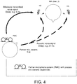
- FIG. 4 shows a typical situation where an acoustically propagated target signal is received later than a wirelessly transmitted target signal at the hearing aid user.
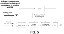
- FIG. 5 shows an example block diagram of a hearing device receiving a target signal via a wireless link as well as via an acoustic propagation path.
- the wirelessly received signal is e.g. used for improved transient detection (block Transient Reduction ) and level estimation (block Compression and amplification ).
- the hearing-loss compensation (HLC) block in any hearing aid applies a frequency-dependent and time-varying gain to the input sound signal.
- the HLC gain in a particular frequency-band is a function of the signal power in the frequency-band at the playback time.
- having "future" signal regions available allows a more accurate estimation of the signal power in a particular frequency region, which in turn allows a more accurate estimate of the HLC gain to be applied.
- connection or “coupled” as used herein may include wirelessly connected or coupled.
- the term “and/or” includes any and all combinations of one or more of the associated listed items. The steps of any disclosed method is not limited to the exact order stated herein, unless expressly stated otherwise.
Claims (16)
- Unité de microphone partenaire (PMIC) conçue pour capter le son d'une source de son cible, le son comprenant une voix de personne (TLK), l'unité de microphone partenaire (PMIC) comprenant• une antenne et un circuit d'émetteur-récepteur (ANT, RF-Rx/Tx) pour établir une liaison audio avec un autre dispositif,• une pluralité d'unités d'entrée IUi , i = 1, 2, ..., M, M étant supérieur ou égal à deux, chaque unité d'entrée comprenant un microphone pour capter le son en provenance de l'environnement de l'unité de microphone partenaire (PMIC) et conçu pour fournir des signaux d'entrée électriques correspondants (X1, ..., XM), chaque signal d'entrée électrique comprenant une composante de signal cible et une composante de signal de bruit ;• un détecteur d'activité vocale (VAD) pour estimer si oui ou non ou avec quelle probabilité, une voix de la personne est présente dans le son actuel en provenance de l'environnement et pour fournir un signal de commande d'activité vocale indicatif de ce dernier, ou est conçu pour recevoir un tel signal de commande d'activité vocale provenant d'un autre dispositif ;• CARACTERISEE EN CE QUE l'unité de microphone partenaire comprend en outre un système de réduction de bruit d'unité à multi-entrées (NRS) pour fournir une estimation Ŝ du son s comprenant la voix de la personne, le système de réduction de bruit d'unité à multi-entrées (NRS) comprenant une unité de filtrage de formateur de faisceau à multi-entrées (BF) couplée de manière opérationnelle à ladite pluralité d'unités d'entrée IUi , i = 1, M, et conçue pour déterminer des poids de filtre afin de fournir un signal formé en faisceau (Y), les composantes de signal provenant d'autres directions qu'une direction de la source sonore étant atténuées, tandis que les composantes du signal provenant de la direction de la source sonore sont laissées non-atténuées ou sont moins atténuées par rapport aux composantes de signal provenant desdites autres directions ;où l'unité de filtrage de formateur de faisceau à multi-entrées (BF) comprend un formateur de faisceau adaptatif, et
où le système de réduction de bruit d'unité à multi-entrées (NRS) est conçu pour• estimer une densité spectrale de puissance de bruit d'un bruit de fond perturbateur lorsque la voix de la personne (TLK) n'est pas présente, ou est présente avec une probabilité inférieure à un niveau prédéfini, ou pour recevoir cette estimation en provenance d'un autre dispositif, et• estimer de manière adaptative un vecteur d'aspect actuel d(k, m) de l'unité de filtrage de formateur de faisceau (BF) pour un son provenant d'une source sonore située à un emplacement spécifique par rapport à la personne (TLK) portant l'unité de microphone partenaire (PMIC), où l'emplacement spécifique par rapport à la personne (TLK) est l'emplacement de la bouche de la personne. - Unité de microphone partenaire selon la revendication 1, dans laquelle l'unité de filtrage du formateur de faisceau à multi-entrées comprend un formateur de faisceau MVDR.
- Unité de microphone partenaire (PMIC) selon la revendication 1 ou 2, dans laquelle l'unité de filtrage de formateur de faisceau variable à multicanaux (BF) comprend un filtre MVDR fournissant des poids de filtre wmvdr(k, m), lesdits poids de filtre wmvdr(k, m) étant basés sur un vecteur d'aspect d(k, m) et une matrice de covariance d'unité inter-entrée pour le signal de bruit, le vecteur d'aspect d(k, m) étant un vecteur à M dimensions comprenant des éléments (i = 1, 2, ..., M), le ième élément d i(k, m) définissant une fonction de transfert acoustique allant de la source sonore cible à un emplacement donné par rapport aux unités d'entrée de l'unité de microphone partenaire jusqu'à la ième unité d'entrée, ou la fonction de transfert acoustique relative allant de la ième unité d'entrée jusqu'à une unité d'entrée de référence.
- Unité de microphone partenaire (PMIC) selon l'une quelconque des revendications 1 à 3, dans laquelle au moins deux des unités d'entrée comprennent un détecteur de niveau pour détecter un niveau d'entrée du son capté par les microphones des unités d'entrée en question, et dans laquelle le détecteur d'activité vocale (VAD) est conçu pour baser le signal de commande d'activité vocale sur la différence entre les niveaux d'entrée des signaux d'entrée électriques respectifs des microphones.
- Unité de microphone partenaire (PMIC) selon l'une quelconque des revendications 1 à 4, conçue pour être portée par une personne (TLK).
- Unité de microphone partenaire (PMIC) selon l'une quelconque des revendications 1 à 5, comprenant une mémoire (MEM) comprenant un vecteur d'aspect de référence prédéfini définissant une direction spatiale de référence allant de l'unité de microphone partenaire (PMIC) jusqu'à la source sonore cible.
- Unité de microphone partenaire (PMIC) selon l'une quelconque des revendications 1 à 6, dans laquelle le système de réduction de bruit d'unité à multi-entrées (NRS) est conçu pour mettre à jour un vecteur d'aspect ( d ) lorsque le son cible est présent ou présent avec probabilité supérieure à une valeur prédéfinie.
- Unité de microphone partenaire (PMIC) selon la revendication 7, conçue pour limiter ladite mise à jour du vecteur d'aspect ( d ) en comparant des poids de formateur de faisceau déterminés actuellement correspondant à un vecteur d'aspect actuel avec des poids par défaut correspondant au vecteur d'aspect de référence, et pour limiter ou négliger les poids de formateur de faisceau déterminés actuellement s'ils diffèrent des poids par défaut de plus d'une quantité prédéfinie absolue ou relative.
- Unité de microphone partenaire (PMIC) selon l'une quelconque des revendications 1 à 8, comprenant une mémoire (MEM) qui comprend des matrices de covariance de bruit inter-microphone de référence prédéfinies de l'unité de microphone partenaire (PMIC).
- Unité de microphone partenaire (PMIC) selon la revendication 9, conçue pour commander la mise à jour de la densité spectrale de puissance de bruit d'un bruit de fond perturbateur en comparant les matrices de covariance de bruit inter-microphone déterminées actuellement (Cw) avec les matrices de covariance de bruit inter-microphone de référence, et pour limiter ou négliger la mise à jour de la densité spectrale de puissance de bruit d'un bruit de fond perturbateur si les matrices de covariance de bruit inter-microphone déterminées actuellement diffèrent des matrices de covariance de bruit inter-microphone de référence de plus d'une valeur absolue ou relative prédéfinie .
- Unité de microphone partenaire (PMIC) selon l'une quelconque des revendications 1 à 10, comprenant un élément de fixation pour attacher ladite unité de microphone partenaire à l'utilisateur.
- Unité de microphone partenaire (PMIC) selon l'une quelconque des revendications 1 à 11, conçue pour transmettre l'estimation Ŝ du son s comprenant la voix de la personne à un autre dispositif, par exemple un dispositif auditif (HD).
- Système auditif comprenant une unité de microphone partenaire (PMIC) selon l'une quelconque des revendications 1 à 12 et un dispositif auditif (HD), par exemple une aide auditive, où le dispositif auditif (HD) comprend une antenne et un circuit d'émetteur-récepteur (ANT, Rx/Tx) pour établir une liaison de communication avec et recevoir un signal audio (PS) comprenant une estimation du son s comprenant une voix de la personne (TLK) en provenance de ladite unité de microphone partenaire (PMIC).
- Système auditif selon la revendication 13, où le dispositif auditif (HD) comprend un transducteur d'entrée (MIC) pour capter un son provenant de l'environnement du dispositif auditif (HD) et pour fournir un signal d'entrée de dispositif auditif électrique (INm), une unité de traitement de signal (SPU) pour appliquer un ou plusieurs algorithmes de traitement au signal d'entrée de dispositif auditif électrique (INm), ou à un signal issu de celui-ci (RIN), et pour fournir un signal de dispositif auditif traité (PRS), et une unité de sortie (OU) pour fournir des stimuli (OUT) perçus par un utilisateur (U) en tant que son basé sur le signal de dispositif auditive traité (PRS) ou un signal issu de celui-ci, et une unité d'analyse conçue pour analyser le signal audio reçu de l'unité de microphone partenaire (PMIC), et pour générer un ou plusieurs signaux de commande pour commander ledit un ou plusieurs algorithmes de traitement.
- Système auditif selon la revendication 13 ou 14, où le dispositif auditif (HD) comprend une aide auditive conçue pour fournir un gain dépendant de la fréquence, et/ou une compression dépendant du niveau, et/ou une transposition d'une ou de plusieurs gammes de fréquences à une ou plusieurs autres gammes de fréquences, pour compenser une déficience auditive d'un utilisateur (U).
- Utilisation d'une unité de microphone partenaire selon l'une quelconque des revendications 1 à 12 dans un système auditif selon l'une quelconque des revendications 13 à 15, conçue pour capter et réduire un bruit dans une voix d'un interlocuteur ou d'un partenaire de communication et pour transmettre le signal de bruit réduit à un dispositif auditif porté par un utilisateur.
Priority Applications (1)
| Application Number | Priority Date | Filing Date | Title |
|---|---|---|---|
| EP16154994.4A EP3057340B1 (fr) | 2015-02-13 | 2016-02-10 | Unité de microphone partenaire et système auditif comprenant une unité de microphone partenaire |
Applications Claiming Priority (2)
| Application Number | Priority Date | Filing Date | Title |
|---|---|---|---|
| EP15154949 | 2015-02-13 | ||
| EP16154994.4A EP3057340B1 (fr) | 2015-02-13 | 2016-02-10 | Unité de microphone partenaire et système auditif comprenant une unité de microphone partenaire |
Publications (2)
| Publication Number | Publication Date |
|---|---|
| EP3057340A1 EP3057340A1 (fr) | 2016-08-17 |
| EP3057340B1 true EP3057340B1 (fr) | 2019-05-22 |
Family
ID=52589234
Family Applications (1)
| Application Number | Title | Priority Date | Filing Date |
|---|---|---|---|
| EP16154994.4A Active EP3057340B1 (fr) | 2015-02-13 | 2016-02-10 | Unité de microphone partenaire et système auditif comprenant une unité de microphone partenaire |
Country Status (4)
| Country | Link |
|---|---|
| US (2) | US9832576B2 (fr) |
| EP (1) | EP3057340B1 (fr) |
| CN (1) | CN105898662B (fr) |
| DK (1) | DK3057340T3 (fr) |
Families Citing this family (26)
| Publication number | Priority date | Publication date | Assignee | Title |
|---|---|---|---|---|
| EP3468229A1 (fr) * | 2017-10-06 | 2019-04-10 | Oticon A/s | Instrument à unité de détection à distance d'objets |
| US10244300B2 (en) | 2014-04-30 | 2019-03-26 | Oticon A/S | Instrument with remote object detection unit |
| EP3101919B1 (fr) * | 2015-06-02 | 2020-02-19 | Oticon A/s | Système auditif pair à pair |
| US10231062B2 (en) * | 2016-05-30 | 2019-03-12 | Oticon A/S | Hearing aid comprising a beam former filtering unit comprising a smoothing unit |
| DK3285501T3 (da) * | 2016-08-16 | 2020-02-17 | Oticon As | Høresystem, der omfatter et høreapparat og en mikrofonenhed til at opfange en brugers egen stemme |
| DK3306956T3 (da) * | 2016-10-05 | 2019-10-28 | Oticon As | En binaural stråleformerfiltreringsenhed, et høresystem og en høreanordning |
| EP3913930A1 (fr) * | 2016-12-08 | 2021-11-24 | GN Hearing A/S | Dispositifs auditifs, dispositifs d'accessoires utilisateur et procédé de mise à jour d'une configuration de dispositif auditif |
| EP3373603B1 (fr) * | 2017-03-09 | 2020-07-08 | Oticon A/s | Dispositif auditif comprenant un récepteur de son sans fil |
| DE102017215823B3 (de) * | 2017-09-07 | 2018-09-20 | Sivantos Pte. Ltd. | Verfahren zum Betrieb eines Hörgerätes |
| WO2019082060A1 (fr) * | 2017-10-23 | 2019-05-02 | Cochlear Limited | Assistance avancée pour communication assistée par prothèse |
| CN111295895B (zh) | 2017-10-23 | 2021-10-15 | 科利耳有限公司 | 一种身体穿戴装置、多用途装置和方法 |
| EP3534624B1 (fr) * | 2018-02-28 | 2024-04-17 | Sivantos Pte. Ltd. | Procédé de fonctionnement d'un dispositif de correction auditive |
| DE102018203907A1 (de) * | 2018-02-28 | 2019-08-29 | Sivantos Pte. Ltd. | Verfahren zum Betrieb eines Hörgerätes |
| DK3582513T3 (da) * | 2018-06-12 | 2022-01-31 | Oticon As | Høreanordning omfattende adaptiv lydkildefrekvensreduktion |
| KR101942506B1 (ko) * | 2018-07-16 | 2019-01-28 | 주식회사 프린트플랜 | 음원 보조 인식 장치 |
| NL2021308B1 (en) * | 2018-07-16 | 2020-01-24 | Hazelebach & Van Der Ven Holding B V | Methods for a voice processing system |
| US11373653B2 (en) * | 2019-01-19 | 2022-06-28 | Joseph Alan Epstein | Portable speech recognition and assistance using non-audio or distorted-audio techniques |
| EP3694229A1 (fr) * | 2019-02-08 | 2020-08-12 | Oticon A/s | Dispositif auditif comprenant un système de réduction du bruit |
| DE102019219510B3 (de) | 2019-12-12 | 2020-12-17 | Sivantos Pte. Ltd. | Verfahren, bei welchem zwei Hörgeräte miteinander gekoppelt werden, sowie Hörgerät |
| US11513765B2 (en) * | 2020-01-10 | 2022-11-29 | Airoha Technology Corp. | Bluetooth audio device, Bluetooth audio system and operating method thereof |
| DE102020201615B3 (de) * | 2020-02-10 | 2021-08-12 | Sivantos Pte. Ltd. | Hörsystem mit mindestens einem im oder am Ohr des Nutzers getragenen Hörinstrument sowie Verfahren zum Betrieb eines solchen Hörsystems |
| EP3866489B1 (fr) | 2020-02-13 | 2023-11-22 | Sonova AG | Appariement de dispositifs auditifs avec un algorithme d'apprentissage machine |
| CN113099371B (zh) * | 2021-04-15 | 2022-08-12 | 西安音悦电子科技有限公司 | 一种新型无线助听器系统以及自助替换耳机实现方法 |
| CN113099370A (zh) * | 2021-04-15 | 2021-07-09 | 西安音悦电子科技有限公司 | 一种新型智能助听器系统以及多场景使用方法 |
| EP4161103A1 (fr) * | 2021-09-29 | 2023-04-05 | Oticon A/s | Réseau de microphones à distance pour prothèse auditive |
| CN117041847B (zh) * | 2023-09-29 | 2023-12-22 | 舒耳美(张家港)高科技有限公司 | 用于助听器中自适应传声器匹配方法及系统 |
Family Cites Families (16)
| Publication number | Priority date | Publication date | Assignee | Title |
|---|---|---|---|---|
| KR100884968B1 (ko) * | 2003-12-24 | 2009-02-23 | 노키아 코포레이션 | 상보적 노이즈 분리 필터를 이용한 효율적 빔포밍 방법 |
| US8068619B2 (en) * | 2006-05-09 | 2011-11-29 | Fortemedia, Inc. | Method and apparatus for noise suppression in a small array microphone system |
| DK1863320T3 (da) * | 2006-06-01 | 2011-01-24 | Phonak Ag | Fremgangsmåde til indstilling af et høreapparatsystem |
| US7738666B2 (en) * | 2006-06-01 | 2010-06-15 | Phonak Ag | Method for adjusting a system for providing hearing assistance to a user |
| US20100150387A1 (en) * | 2007-01-10 | 2010-06-17 | Phonak Ag | System and method for providing hearing assistance to a user |
| DK2088802T3 (da) * | 2008-02-07 | 2013-10-14 | Oticon As | Fremgangsmåde til estimering af lydsignalers vægtningsfunktion i et høreapparat |
| CN101510426B (zh) * | 2009-03-23 | 2013-03-27 | 北京中星微电子有限公司 | 一种噪声消除方法及系统 |
| CN101593522B (zh) * | 2009-07-08 | 2011-09-14 | 清华大学 | 一种全频域数字助听方法和设备 |
| KR101782050B1 (ko) * | 2010-09-17 | 2017-09-28 | 삼성전자주식회사 | 비등간격으로 배치된 마이크로폰을 이용한 음질 향상 장치 및 방법 |
| EP2563045B1 (fr) * | 2011-08-23 | 2014-07-23 | Oticon A/s | Procédé et système d'écoute binaurale pour maximiser l'effet d'oreille meilleure. |
| EP3462452A1 (fr) * | 2012-08-24 | 2019-04-03 | Oticon A/s | Estimation de bruit destinée à être utilisée avec réduction de bruit et annulation d'écho dans une communication personnelle |
| US9107001B2 (en) * | 2012-10-02 | 2015-08-11 | Mh Acoustics, Llc | Earphones having configurable microphone arrays |
| US8965016B1 (en) * | 2013-08-02 | 2015-02-24 | Starkey Laboratories, Inc. | Automatic hearing aid adaptation over time via mobile application |
| DK2835986T3 (en) * | 2013-08-09 | 2018-01-08 | Oticon As | Hearing aid with input transducer and wireless receiver |
| US9800981B2 (en) * | 2014-09-05 | 2017-10-24 | Bernafon Ag | Hearing device comprising a directional system |
| CN106797519B (zh) * | 2014-10-02 | 2020-06-09 | 索诺瓦公司 | 在自组织网络和对应系统中在用户之间提供听力辅助的方法 |
-
2016
- 2016-02-10 EP EP16154994.4A patent/EP3057340B1/fr active Active
- 2016-02-10 DK DK16154994.4T patent/DK3057340T3/da active
- 2016-02-12 US US15/042,944 patent/US9832576B2/en active Active
- 2016-02-15 CN CN201610086210.6A patent/CN105898662B/zh active Active
-
2017
- 2017-10-24 US US15/792,434 patent/US10129663B2/en active Active
Non-Patent Citations (1)
| Title |
|---|
| None * |
Also Published As
| Publication number | Publication date |
|---|---|
| EP3057340A1 (fr) | 2016-08-17 |
| CN105898662A (zh) | 2016-08-24 |
| US20160241975A1 (en) | 2016-08-18 |
| DK3057340T3 (da) | 2019-08-19 |
| US9832576B2 (en) | 2017-11-28 |
| US20180048969A1 (en) | 2018-02-15 |
| CN105898662B (zh) | 2020-07-17 |
| US10129663B2 (en) | 2018-11-13 |
Similar Documents
| Publication | Publication Date | Title |
|---|---|---|
| US10129663B2 (en) | Partner microphone unit and a hearing system comprising a partner microphone unit | |
| US9860656B2 (en) | Hearing system comprising a separate microphone unit for picking up a users own voice | |
| EP3285501B1 (fr) | Système auditif comprenant un dispositif auditif et une unité de microphone servant à capter la voix d'un utilisateur | |
| US20230269549A1 (en) | Hearing aid device for hands free communication | |
| EP3101919B1 (fr) | Système auditif pair à pair | |
| EP3051844B1 (fr) | Système auditif binauriculaire | |
| US11564043B2 (en) | Hearing device and a hearing system comprising a multitude of adaptive two channel beamformers | |
| US9986346B2 (en) | Binaural hearing system and a hearing device comprising a beamformer unit | |
| US11510017B2 (en) | Hearing device comprising a microphone adapted to be located at or in the ear canal of a user | |
| US11259127B2 (en) | Hearing device adapted to provide an estimate of a user's own voice |
Legal Events
| Date | Code | Title | Description |
|---|---|---|---|
| PUAI | Public reference made under article 153(3) epc to a published international application that has entered the european phase |
Free format text: ORIGINAL CODE: 0009012 |
|
| AK | Designated contracting states |
Kind code of ref document: A1 Designated state(s): AL AT BE BG CH CY CZ DE DK EE ES FI FR GB GR HR HU IE IS IT LI LT LU LV MC MK MT NL NO PL PT RO RS SE SI SK SM TR |
|
| AX | Request for extension of the european patent |
Extension state: BA ME |
|
| STAA | Information on the status of an ep patent application or granted ep patent |
Free format text: STATUS: REQUEST FOR EXAMINATION WAS MADE |
|
| 17P | Request for examination filed |
Effective date: 20170217 |
|
| RBV | Designated contracting states (corrected) |
Designated state(s): AL AT BE BG CH CY CZ DE DK EE ES FI FR GB GR HR HU IE IS IT LI LT LU LV MC MK MT NL NO PL PT RO RS SE SI SK SM TR |
|
| STAA | Information on the status of an ep patent application or granted ep patent |
Free format text: STATUS: EXAMINATION IS IN PROGRESS |
|
| 17Q | First examination report despatched |
Effective date: 20180525 |
|
| GRAP | Despatch of communication of intention to grant a patent |
Free format text: ORIGINAL CODE: EPIDOSNIGR1 |
|
| STAA | Information on the status of an ep patent application or granted ep patent |
Free format text: STATUS: GRANT OF PATENT IS INTENDED |
|
| INTG | Intention to grant announced |
Effective date: 20181212 |
|
| GRAS | Grant fee paid |
Free format text: ORIGINAL CODE: EPIDOSNIGR3 |
|
| GRAA | (expected) grant |
Free format text: ORIGINAL CODE: 0009210 |
|
| STAA | Information on the status of an ep patent application or granted ep patent |
Free format text: STATUS: THE PATENT HAS BEEN GRANTED |
|
| AK | Designated contracting states |
Kind code of ref document: B1 Designated state(s): AL AT BE BG CH CY CZ DE DK EE ES FI FR GB GR HR HU IE IS IT LI LT LU LV MC MK MT NL NO PL PT RO RS SE SI SK SM TR |
|
| REG | Reference to a national code |
Ref country code: GB Ref legal event code: FG4D |
|
| REG | Reference to a national code |
Ref country code: CH Ref legal event code: EP |
|
| REG | Reference to a national code |
Ref country code: IE Ref legal event code: FG4D |
|
| REG | Reference to a national code |
Ref country code: DE Ref legal event code: R096 Ref document number: 602016014151 Country of ref document: DE |
|
| REG | Reference to a national code |
Ref country code: AT Ref legal event code: REF Ref document number: 1137551 Country of ref document: AT Kind code of ref document: T Effective date: 20190615 |
|
| REG | Reference to a national code |
Ref country code: DK Ref legal event code: T3 Effective date: 20190816 |
|
| REG | Reference to a national code |
Ref country code: NL Ref legal event code: MP Effective date: 20190522 |
|
| REG | Reference to a national code |
Ref country code: LT Ref legal event code: MG4D |
|
| PG25 | Lapsed in a contracting state [announced via postgrant information from national office to epo] |
Ref country code: PT Free format text: LAPSE BECAUSE OF FAILURE TO SUBMIT A TRANSLATION OF THE DESCRIPTION OR TO PAY THE FEE WITHIN THE PRESCRIBED TIME-LIMIT Effective date: 20190922 Ref country code: ES Free format text: LAPSE BECAUSE OF FAILURE TO SUBMIT A TRANSLATION OF THE DESCRIPTION OR TO PAY THE FEE WITHIN THE PRESCRIBED TIME-LIMIT Effective date: 20190522 Ref country code: HR Free format text: LAPSE BECAUSE OF FAILURE TO SUBMIT A TRANSLATION OF THE DESCRIPTION OR TO PAY THE FEE WITHIN THE PRESCRIBED TIME-LIMIT Effective date: 20190522 Ref country code: SE Free format text: LAPSE BECAUSE OF FAILURE TO SUBMIT A TRANSLATION OF THE DESCRIPTION OR TO PAY THE FEE WITHIN THE PRESCRIBED TIME-LIMIT Effective date: 20190522 Ref country code: AL Free format text: LAPSE BECAUSE OF FAILURE TO SUBMIT A TRANSLATION OF THE DESCRIPTION OR TO PAY THE FEE WITHIN THE PRESCRIBED TIME-LIMIT Effective date: 20190522 Ref country code: NO Free format text: LAPSE BECAUSE OF FAILURE TO SUBMIT A TRANSLATION OF THE DESCRIPTION OR TO PAY THE FEE WITHIN THE PRESCRIBED TIME-LIMIT Effective date: 20190822 Ref country code: FI Free format text: LAPSE BECAUSE OF FAILURE TO SUBMIT A TRANSLATION OF THE DESCRIPTION OR TO PAY THE FEE WITHIN THE PRESCRIBED TIME-LIMIT Effective date: 20190522 Ref country code: LT Free format text: LAPSE BECAUSE OF FAILURE TO SUBMIT A TRANSLATION OF THE DESCRIPTION OR TO PAY THE FEE WITHIN THE PRESCRIBED TIME-LIMIT Effective date: 20190522 Ref country code: NL Free format text: LAPSE BECAUSE OF FAILURE TO SUBMIT A TRANSLATION OF THE DESCRIPTION OR TO PAY THE FEE WITHIN THE PRESCRIBED TIME-LIMIT Effective date: 20190522 |
|
| PG25 | Lapsed in a contracting state [announced via postgrant information from national office to epo] |
Ref country code: RS Free format text: LAPSE BECAUSE OF FAILURE TO SUBMIT A TRANSLATION OF THE DESCRIPTION OR TO PAY THE FEE WITHIN THE PRESCRIBED TIME-LIMIT Effective date: 20190522 Ref country code: BG Free format text: LAPSE BECAUSE OF FAILURE TO SUBMIT A TRANSLATION OF THE DESCRIPTION OR TO PAY THE FEE WITHIN THE PRESCRIBED TIME-LIMIT Effective date: 20190822 Ref country code: GR Free format text: LAPSE BECAUSE OF FAILURE TO SUBMIT A TRANSLATION OF THE DESCRIPTION OR TO PAY THE FEE WITHIN THE PRESCRIBED TIME-LIMIT Effective date: 20190823 Ref country code: LV Free format text: LAPSE BECAUSE OF FAILURE TO SUBMIT A TRANSLATION OF THE DESCRIPTION OR TO PAY THE FEE WITHIN THE PRESCRIBED TIME-LIMIT Effective date: 20190522 |
|
| REG | Reference to a national code |
Ref country code: AT Ref legal event code: MK05 Ref document number: 1137551 Country of ref document: AT Kind code of ref document: T Effective date: 20190522 |
|
| PG25 | Lapsed in a contracting state [announced via postgrant information from national office to epo] |
Ref country code: AT Free format text: LAPSE BECAUSE OF FAILURE TO SUBMIT A TRANSLATION OF THE DESCRIPTION OR TO PAY THE FEE WITHIN THE PRESCRIBED TIME-LIMIT Effective date: 20190522 Ref country code: EE Free format text: LAPSE BECAUSE OF FAILURE TO SUBMIT A TRANSLATION OF THE DESCRIPTION OR TO PAY THE FEE WITHIN THE PRESCRIBED TIME-LIMIT Effective date: 20190522 Ref country code: SK Free format text: LAPSE BECAUSE OF FAILURE TO SUBMIT A TRANSLATION OF THE DESCRIPTION OR TO PAY THE FEE WITHIN THE PRESCRIBED TIME-LIMIT Effective date: 20190522 Ref country code: RO Free format text: LAPSE BECAUSE OF FAILURE TO SUBMIT A TRANSLATION OF THE DESCRIPTION OR TO PAY THE FEE WITHIN THE PRESCRIBED TIME-LIMIT Effective date: 20190522 Ref country code: CZ Free format text: LAPSE BECAUSE OF FAILURE TO SUBMIT A TRANSLATION OF THE DESCRIPTION OR TO PAY THE FEE WITHIN THE PRESCRIBED TIME-LIMIT Effective date: 20190522 |
|
| REG | Reference to a national code |
Ref country code: DE Ref legal event code: R097 Ref document number: 602016014151 Country of ref document: DE |
|
| PG25 | Lapsed in a contracting state [announced via postgrant information from national office to epo] |
Ref country code: SM Free format text: LAPSE BECAUSE OF FAILURE TO SUBMIT A TRANSLATION OF THE DESCRIPTION OR TO PAY THE FEE WITHIN THE PRESCRIBED TIME-LIMIT Effective date: 20190522 Ref country code: IT Free format text: LAPSE BECAUSE OF FAILURE TO SUBMIT A TRANSLATION OF THE DESCRIPTION OR TO PAY THE FEE WITHIN THE PRESCRIBED TIME-LIMIT Effective date: 20190522 |
|
| PLBE | No opposition filed within time limit |
Free format text: ORIGINAL CODE: 0009261 |
|
| STAA | Information on the status of an ep patent application or granted ep patent |
Free format text: STATUS: NO OPPOSITION FILED WITHIN TIME LIMIT |
|
| PG25 | Lapsed in a contracting state [announced via postgrant information from national office to epo] |
Ref country code: TR Free format text: LAPSE BECAUSE OF FAILURE TO SUBMIT A TRANSLATION OF THE DESCRIPTION OR TO PAY THE FEE WITHIN THE PRESCRIBED TIME-LIMIT Effective date: 20190522 |
|
| 26N | No opposition filed |
Effective date: 20200225 |
|
| PG25 | Lapsed in a contracting state [announced via postgrant information from national office to epo] |
Ref country code: PL Free format text: LAPSE BECAUSE OF FAILURE TO SUBMIT A TRANSLATION OF THE DESCRIPTION OR TO PAY THE FEE WITHIN THE PRESCRIBED TIME-LIMIT Effective date: 20190522 |
|
| PG25 | Lapsed in a contracting state [announced via postgrant information from national office to epo] |
Ref country code: SI Free format text: LAPSE BECAUSE OF FAILURE TO SUBMIT A TRANSLATION OF THE DESCRIPTION OR TO PAY THE FEE WITHIN THE PRESCRIBED TIME-LIMIT Effective date: 20190522 |
|
| REG | Reference to a national code |
Ref country code: BE Ref legal event code: MM Effective date: 20200229 |
|
| PG25 | Lapsed in a contracting state [announced via postgrant information from national office to epo] |
Ref country code: LU Free format text: LAPSE BECAUSE OF NON-PAYMENT OF DUE FEES Effective date: 20200210 Ref country code: MC Free format text: LAPSE BECAUSE OF FAILURE TO SUBMIT A TRANSLATION OF THE DESCRIPTION OR TO PAY THE FEE WITHIN THE PRESCRIBED TIME-LIMIT Effective date: 20190522 |
|
| PG25 | Lapsed in a contracting state [announced via postgrant information from national office to epo] |
Ref country code: IE Free format text: LAPSE BECAUSE OF NON-PAYMENT OF DUE FEES Effective date: 20200210 |
|
| PG25 | Lapsed in a contracting state [announced via postgrant information from national office to epo] |
Ref country code: BE Free format text: LAPSE BECAUSE OF NON-PAYMENT OF DUE FEES Effective date: 20200229 |
|
| PG25 | Lapsed in a contracting state [announced via postgrant information from national office to epo] |
Ref country code: MT Free format text: LAPSE BECAUSE OF FAILURE TO SUBMIT A TRANSLATION OF THE DESCRIPTION OR TO PAY THE FEE WITHIN THE PRESCRIBED TIME-LIMIT Effective date: 20190522 Ref country code: CY Free format text: LAPSE BECAUSE OF FAILURE TO SUBMIT A TRANSLATION OF THE DESCRIPTION OR TO PAY THE FEE WITHIN THE PRESCRIBED TIME-LIMIT Effective date: 20190522 |
|
| PG25 | Lapsed in a contracting state [announced via postgrant information from national office to epo] |
Ref country code: MK Free format text: LAPSE BECAUSE OF FAILURE TO SUBMIT A TRANSLATION OF THE DESCRIPTION OR TO PAY THE FEE WITHIN THE PRESCRIBED TIME-LIMIT Effective date: 20190522 Ref country code: IS Free format text: LAPSE BECAUSE OF FAILURE TO SUBMIT A TRANSLATION OF THE DESCRIPTION OR TO PAY THE FEE WITHIN THE PRESCRIBED TIME-LIMIT Effective date: 20190922 |
|
| PGFP | Annual fee paid to national office [announced via postgrant information from national office to epo] |
Ref country code: FR Payment date: 20230127 Year of fee payment: 8 Ref country code: DK Payment date: 20230127 Year of fee payment: 8 Ref country code: CH Payment date: 20230307 Year of fee payment: 8 |
|
| PGFP | Annual fee paid to national office [announced via postgrant information from national office to epo] |
Ref country code: GB Payment date: 20230127 Year of fee payment: 8 Ref country code: DE Payment date: 20230131 Year of fee payment: 8 |