EP3057173A1 - Non-reciprocal circuit - Google Patents
Non-reciprocal circuit Download PDFInfo
- Publication number
- EP3057173A1 EP3057173A1 EP14852106.5A EP14852106A EP3057173A1 EP 3057173 A1 EP3057173 A1 EP 3057173A1 EP 14852106 A EP14852106 A EP 14852106A EP 3057173 A1 EP3057173 A1 EP 3057173A1
- Authority
- EP
- European Patent Office
- Prior art keywords
- input
- ground conductor
- reciprocal circuit
- magnetic material
- output terminals
- Prior art date
- Legal status (The legal status is an assumption and is not a legal conclusion. Google has not performed a legal analysis and makes no representation as to the accuracy of the status listed.)
- Granted
Links
- 239000004020 conductor Substances 0.000 claims abstract description 186
- 239000000696 magnetic material Substances 0.000 claims abstract description 79
- 239000000758 substrate Substances 0.000 claims abstract description 47
- 239000002184 metal Substances 0.000 claims abstract description 30
- 230000008878 coupling Effects 0.000 claims description 17
- 238000010168 coupling process Methods 0.000 claims description 17
- 238000005859 coupling reaction Methods 0.000 claims description 17
- 239000011810 insulating material Substances 0.000 claims description 13
- 239000002245 particle Substances 0.000 claims description 9
- 230000002238 attenuated effect Effects 0.000 description 11
- 125000006850 spacer group Chemical group 0.000 description 6
- 230000000694 effects Effects 0.000 description 5
- 230000005540 biological transmission Effects 0.000 description 4
- 238000000034 method Methods 0.000 description 4
- 239000000853 adhesive Substances 0.000 description 2
- 230000001070 adhesive effect Effects 0.000 description 2
- 239000003990 capacitor Substances 0.000 description 2
- 229910000859 α-Fe Inorganic materials 0.000 description 1
Images


Classifications
-
- H—ELECTRICITY
- H01—ELECTRIC ELEMENTS
- H01P—WAVEGUIDES; RESONATORS, LINES, OR OTHER DEVICES OF THE WAVEGUIDE TYPE
- H01P1/00—Auxiliary devices
- H01P1/32—Non-reciprocal transmission devices
- H01P1/38—Circulators
-
- H—ELECTRICITY
- H01—ELECTRIC ELEMENTS
- H01P—WAVEGUIDES; RESONATORS, LINES, OR OTHER DEVICES OF THE WAVEGUIDE TYPE
- H01P1/00—Auxiliary devices
- H01P1/32—Non-reciprocal transmission devices
- H01P1/38—Circulators
- H01P1/383—Junction circulators, e.g. Y-circulators
- H01P1/387—Strip line circulators
-
- H—ELECTRICITY
- H03—ELECTRONIC CIRCUITRY
- H03H—IMPEDANCE NETWORKS, e.g. RESONANT CIRCUITS; RESONATORS
- H03H7/00—Multiple-port networks comprising only passive electrical elements as network components
- H03H7/004—Capacitive coupling circuits not otherwise provided for
Definitions
- the present invention relates to a non-reciprocal circuit such as a circulator or isolator mainly used for communication equipment.
- a non-reciprocal circuit such as a circulator and isolator has characteristics of transferring a signal in the transmission direction almost without attenuation, and transferring a signal in the reverse direction with large attenuation, and is sometimes used for a transmitting/receiving circuit of communication equipment.
- Patent Document 1 discloses a non-reciprocal circuit that has trifurcated microstrip lines formed on a magnetic material applied with a bias magnetic field by a permanent magnet.
- Patent Document Japanese Patent Laid-Open No.8-125411 ( FIG. 1 ).
- the conventional non-reciprocal circuit has to draw the input/output terminals to the outside of the permanent magnet, which offers a problem of increasing the size its magnetic material.
- the electrical characteristics of the input/output terminals on the magnetic material vary owing to the effect of the bias magnetic field applied by the permanent magnet. Accordingly, long input/output terminals on the magnetic material are easily affected by the setting position of the permanent magnet and the variation in the intensity of the magnetic field, which offers a problem of varying the electrical characteristics of the input/output terminals at mass production.
- the non-reciprocal circuit In addition, to connect the non-reciprocal circuit to a dielectric substrate, it requires wire connection or ribbon connection, which sometimes cannot achieve stable reflection characteristics. In addition, as for the wire connection or ribbon connection, mounting it on the substrate requires a process separate from the reflow mounting, which presents a problem of increasing the mounting cost.
- the present invention is implemented to solve the foregoing problems. Therefore it is an object of the present invention to provide a small-sized, low-cost non-reciprocal circuit with stable reflection characteristics.
- a non-reciprocal circuit in accordance with the present invention comprises: a planar magnetic material; a center conductor formed on a top surface of the magnetic material; a first ground conductor formed on the underside of the magnetic material, and having a plurality of cutouts provided around its periphery; a plurality of input/output terminals formed within portions of the cutouts provided in the first ground conductor on the underside of the magnetic material; a dielectric substrate disposed face to face with the underside of the magnetic material; a second ground conductor formed on a top surface of the dielectric substrate, and having a plurality of cutouts provided in the same places as the cutouts provided in the first ground conductor; a plurality of signal conductors formed within portions of the cutouts provided in the second ground conductor on the top surface of the dielectric substrate; a first connector to electrically connect the center conductor to the plurality of input/output terminals; a second connector to electrically connect the input/output terminals and the signal conductors facing each
- the present invention is configured in such a manner that the plurality of input/output terminals are formed within the portions of the cutouts provided in the first ground conductor on the underside of the magnetic material, and the plurality of signal conductors are formed within the portions of the cutouts provided in the second ground conductor on the top surface of the dielectric substrate, that the first connector electrically connects the center conductor with the plurality of input/output terminals, and the second connector electrically connects the input/output terminals and the signal conductors facing each other, and that the first ground conductor is electrically connected with the second ground conductor. Accordingly, it offers an advantage of being able to achieve stable reflection characteristics, and to implement a small-sized, low-cost non-reciprocal circuit with less variation of the electrical characteristics.
- FIG. 1 is an exploded perspective view showing a non-reciprocal circuit of an embodiment 1 in accordance with the present invention.
- FIG. 2 is a top view showing the magnetic material 3 in the non-reciprocal circuit of FIG. 1 ; and FIG. 3 is a bottom view showing the magnetic material 3 of the non-reciprocal circuit of FIG. 1 .
- FIG. 4 is a top view showing the dielectric substrate 7 in the non-reciprocal circuit of FIG. 1 ; and FIG. 5 is a cross-sectional view showing the non-reciprocal circuit of FIG. 1 .
- a permanent magnet 1 which is composed for a ferrite magnet, for example, is a component to apply a bias magnetic field to the magnetic material 3.
- a spacer 2 is a component to hold a permanent magnet 1 while maintaining the permanent magnet 1 and the magnetic material 3 in a contactless state.
- a center conductor 4 which is composed of a metallic conductor, for example, is formed on the top surface of the magnetic material 3.
- a ground conductor 5 which is a first ground conductor, is formed on the underside of the magnetic material 3, and has cutouts 5a, 5b and 5c provided around its periphery.
- An input/output terminal 6a is formed at a portion within the cutout 5a provided in the ground conductor 5 on the underside of the magnetic material 3.
- An input/output terminal 6b is formed at a portion within the cutout 5b provided in the ground conductor 5 on the underside of the magnetic material 3.
- An input/output terminal 6c is formed at a portion within the cutout 5c provided in the ground conductor 5 on the underside of the magnetic material 3.
- a ground conductor 8 which is a second ground conductor, is formed on the top surface of the dielectric substrate 7, and is provided with cutouts 8a, 8b and 8c that are formed at the same places with the cutouts 5a, 5b and 5c provided in the ground conductor 5.
- a signal conductor 9a is formed at a portion within the cutout 8a provided in the ground conductor 8 on the top surface of the dielectric substrate 7.
- a signal conductor 9b is formed at a portion within the cutout 8b provided in the ground conductor 8 on the top surface of the dielectric substrate 7.
- a signal conductor 9c is formed at a portion within the cutout 8c provided in the ground conductor 8 on the top surface of the dielectric substrate 7.
- a through hole 10a is provided in a manner that it passes through the magnetic material 3 so as to electrically connect the center conductor 4 to the input/output terminal 6a.
- a through hole 10b is provided in a manner that it passes through the magnetic material 3 so as to electrically connect the center conductor 4 to the input/output terminal 6b.
- a through hole 10c is provided in a manner that it passes through the magnetic material 3 so as to electrically connect the center conductor 4 to the input/output terminal 6c.
- the through holes 10a, 10b and 10c constitute a first connector.
- a metal bump 11a electrically connects the input/output terminal 6a and the signal conductor 9a facing each other.
- a metal bump 11b electrically connects the input/output terminal 6b and the signal conductor 9b facing each other.
- a metal bump 11c electrically connects the input/output terminal 6c and the signal conductor 9c facing each other. In FIG. 5 , however, the metal bump 11c, input/output terminal 6c and signal conductor 9c are not drawn.
- Metal bumps 16 electrically connect the ground conductor 5 and the ground conductor 8.
- the metal bumps 11a, 11b and 11c and the metal bumps 16 constitute a second connector.
- a ground conductor 12 which is a third ground conductor, is formed on the underside of the dielectric substrate 7.
- a carrier 14 is a component disposed on the underside of the ground conductor 12.
- An insulating material 15 is filled so as to improve the reliability of the connection between the magnetic material 3 and the dielectric substrate 7.
- the planar magnetic material 3 is disposed under the permanent magnet 1 via the spacer 2 so as to be applied with the bias magnetic field by the permanent magnet 1.
- a signal input via the input/output terminal 6a, 6b or 6c is affected by the bias magnetic field.
- the signal input to the input/output terminal 6a from the signal conductor 9a is transferred to the input/output terminal 6b almost without attenuation, and is output to the signal conductor 9b.
- a greatly attenuated signal is transferred to the input/output terminal 6c so that the greatly attenuated signal is output from the signal conductor 9c.
- a signal input to the input/output terminal 6b from the signal conductor 9b is transferred to the input/output terminal 6c almost without attenuation, and is output to the signal conductor 9c.
- a greatly attenuated signal is transferred to the input/output terminal 6a so that the greatly attenuated signal is output from the signal conductor 9a.
- a signal input to the input/output terminal 6c from the signal conductor 9c is transferred to the input/output terminal 6a almost without attenuation, and is output to the signal conductor 9a.
- a greatly attenuated signal is transferred to the input/output terminal 6b so that the greatly attenuated signal is output from the signal conductor 9b.
- the non-reciprocal circuit has characteristics of providing very little attenuation to the signal in the transmission direction, but providing large attenuation to the signal in the reverse direction.
- the through holes 10a, 10b and 10c electrically connect the center conductor 4 with the input/output terminals 6a, 6b and 6c
- the metal bumps 11a, 11b and 11c electrically connect the input/output terminals 6a, 6b and 6c and the signal conductors 9a, 9b and 9c facing each other.
- the metal bump 11c, input/output terminal 6c and signal conductor 9c are not drawn.
- metal bumps 16 electrically connect the ground conductor 5 to the ground conductor 8.
- the present embodiment 1 it is not necessary for the present embodiment 1 to pull the input/output terminals out of the outer surface of the permanent magnet as in the conventional non-reciprocal circuit, and it can form the input/output terminals 6a, 6b and 6c inside the outer surface of the permanent magnet 1 (see FIG. 3 , for example). Accordingly, it can downsize the magnetic material 3.
- the present embodiment 1 since the length of the input/output terminals on the magnetic material reduces, the present embodiment 1 becomes immune to the effect of the magnet, thereby being able to reduce the variation of the electrical characteristics at mass production.
- the present embodiment 1 does not require any wire connection or ribbon connection. Accordingly, it can achieve stable reflection characteristics (characteristics with very little reflection).
- the present embodiment 1 can carry out reflow mounting of them together with other components (chip capacitors and an IC not shown). Thus it can reduce the mounting cost.
- the present embodiment 1 is configured in such a manner that it has the input/output terminals 6a, 6b and 6c formed within the portions of the cutouts 5a, 5b and 5c provided in the ground conductor 5 on the underside of the magnetic material 3; and has the signal conductors 9a, 9b and 9c formed within the portions of the cutouts 8a, 8b and 8c of the ground conductor 8 on the top surface of the dielectric substrate 7, which cutouts 8a, 8b and 8c are provided at the same places as the cutouts 5a, 5b and 5c provided in the ground conductor 5, wherein the through holes 10a, 10b and 10c electrically connect the center conductor 4 with the input/output terminals 6a, 6b and 6c; the metal bumps 11a, 11b and 11c electrically connect the input/output terminals 6a, 6b and 6c and the signal conductors 9a, 9b and 9c facing each other; and the metal bumps 16 electrically connect the
- the signal conductors 9a, 9b and 9c formed on the top surface of the dielectric substrate 7 are a microstrip line
- the signal conductors 9a, 9b and 9c are not limited to a microstrip line.
- the signal conductors 9a, 9b and 9c can be a transmission line such as a coplanar line and a stripline.
- the present embodiment 1 shows an example having the insulating material 15 filled between the magnetic material 3 and the dielectric substrate 7 to improve the reliability of the connection between them, the insulating material 15 is not an essential component.
- the present embodiment 1 shows an example in which the permanent magnet 1 is disposed over the top surface of the magnetic material 3 via the spacer 2, it is enough for the permanent magnet 1 to be able to apply a bias magnetic field perpendicular to the plane of the magnetic material 3.
- the permanent magnet 1 can be disposed on the underside of the dielectric substrate 7.
- the carrier 14 it can be disposed on the opposite side of the permanent magnet 1 across the magnetic material 3.
- FIG. 6 is a top view showing the magnetic material 3 of a non-reciprocal circuit of an embodiment 2 in accordance with the present invention
- FIG. 7 is a bottom view showing the magnetic material 3 of the non-reciprocal circuit of the embodiment 2 in accordance with the present invention.
- FIG. 8 is a top view showing the dielectric substrate 7 of the non-reciprocal circuit of the embodiment 2 in accordance with the present invention
- FIG. 9 is a cross-sectional view showing the non-reciprocal circuit of the embodiment 2 in accordance with the present invention.
- the present embodiment 2 has the capacitive coupling (electrical connection through a capacitor comprised of the center conductor 4 and the input/output terminals 6a, 6b and 6c) electrically connect the center conductor 4 with the input/output terminals 6a, 6b and 6c.
- the present embodiment 2 connects the center conductor 4 with the input/output terminals 6a, 6b and 6c electrically through the capacitive coupling, it can not only achieve the same effect and advantages as those of the foregoing embodiment 1, but also reduce the fabricating cost because it can obviate the necessity of forming the through holes 10a, 10b and 10c in the magnetic material 3.
- the present embodiment 2 is the same as the foregoing embodiment 1. Thus its detailed description will be omitted.
- FIG. 10 is a cross-sectional view showing a non-reciprocal circuit of an embodiment 3 in accordance with the present invention.
- FIG. 10 since the same reference symbols as those of FIG. 5 designate the same or like components, their description will be omitted.
- an anisotropic conductive adhesive can be used, for example.
- the insulating material 21 constitutes a second connector.
- the foregoing embodiment 1 shows an example in which the second connector is comprised of the metal bumps 11a, 11b and 11c which electrically connect the input/output terminals 6a, 6b and 6c and the signal conductors 9a, 9b and 9c facing each other (in FIG. 5 , the metal bump 11c, the input/output terminal 6c and the signal conductor 9c are not drawn), in the present embodiment 3, the insulating material 21 with the conductive particles 22 dispersed therein electrically connects the input/output terminals 6a, 6b and 6c and the signal conductors 9a, 9b and 9c facing each other. In FIG. 10 , the input/output terminal 6c and the signal conductor 9c are not drawn.
- the present embodiment 3 which electrically connects the input/output terminals 6a, 6b and 6c and the signal conductors 9a, 9b and 9c facing each other through the insulating material 21 with the conductive particles 22 dispersed therein, can achieve the same effect and advantages as the foregoing embodiment 1.
- the circuit is shown in which the first connector is comprised of the through holes 10a, 10b and 10c which pass through the magnetic material 3, and electrically connect the center conductor 4 with the input/output terminals 6a, 6b and 6c.
- the first connector is comprised of the through holes 10a, 10b and 10c which pass through the magnetic material 3, and electrically connect the center conductor 4 with the input/output terminals 6a, 6b and 6c.
- a configuration is also possible which connects the center conductor 4 with the input/output terminals 6a, 6b and 6c electrically through the capacitive coupling.
- FIG. 11 is a cross-sectional view showing a non-reciprocal circuit which connects the center conductor 4 with the input/output terminals 6a, 6b and 6c through the capacitive coupling.
- FIG. 12 is an exploded perspective view showing a non-reciprocal circuit of an embodiment 4 in accordance with the present invention.
- FIG. 13 is a top view showing the magnetic material 3 in the non-reciprocal circuit of FIG. 12
- FIG. 14 is a bottom view showing the magnetic material 3 in the non-reciprocal circuit of FIG. 12 .
- FIG. 15 is a top view showing the dielectric substrate 7 in the non-reciprocal circuit of FIG. 12 .
- the input/output terminal 6a is provided with a stub 31a
- the input/output terminal 6b is provided with a stub 31b
- the input/output terminal 6c is provided with a stub 31c.
- the signal conductor 9a is provided with a stub 32a
- the signal conductor 9b is provided with a stub 32b
- the signal conductor 9c is provided with a stub 32c.
- the present embodiment 4 can correct impedance mismatching, thereby being able to achieve better impedance connection.
- both the input/output terminals 6a, 6b and 6c and the signal conductors 9a, 9b and 9c are provided with the stubs, if either the input/output terminals 6a, 6b and 6c or the signal conductors 9a, 9b and 9c are provided with the stubs, the impedance mismatching at the connecting portions can be corrected.
- the present embodiment 4 can also connect the center conductor 4 with the input/output terminals 6a, 6b and 6c electrically through the capacitive coupling as in the foregoing embodiment 2.
- FIG. 16 is a top view showing the magnetic material 3 when the center conductor 4 and the input/output terminals 6a, 6b and 6c are connected through the capacitive coupling; and FIG. 17 is a bottom view showing the magnetic material 3 when the center conductor 4 with the input/output terminals 6a, 6b and 6c are connected through the capacitive coupling.
- FIG. 18 is a top view showing the dielectric substrate 7 when the center conductor 4 and the input/output terminals 6a, 6b and 6c are connected through the capacitive coupling.
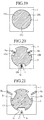
- FIG. 19 is a top view showing the magnetic material 3 of a non-reciprocal circuit of an embodiment 5 in accordance with the present invention.
- FIG. 20 is a bottom view showing the magnetic material 3 of the non-reciprocal circuit of the embodiment 5 in accordance with the present invention.
- FIG. 21 is a top view showing the dielectric substrate 7 of the non-reciprocal circuit of the embodiment 5 in accordance with the present invention
- FIG. 22 is a cross-sectional view showing the non-reciprocal circuit of the embodiment 5 in accordance with the present invention.
- a resistor 41 is connected in series with the input/output terminal 6c.
- a through hole 42 is provided in such a manner as to pass through the dielectric substrate 7 so as to electrically connect the signal conductor 9c with the ground conductor 12.
- a signal input via the input/output terminal 6a, 6b or 6c is affected by the bias magnetic field.
- the signal input to the input/output terminal 6a from the signal conductor 9a is transferred to the input/output terminal 6b almost without attenuation, and is output to the signal conductor 9b.
- a greatly attenuated signal is transferred to the input/output terminal 6c so that the greatly attenuated signal is output from the signal conductor 9c.
- the resistor 41 As for the signal input to the input/output terminal 6b from the signal conductor 9b, unless the resistor 41 is connected to the input/output terminal 6c, it will be transferred to the input/output terminal 6c almost without attenuation so as to be output to the signal conductor 9c as in the foregoing embodiment 1. However, since the resistor 41 is connected to the input/output terminal 6c in the present embodiment 5, the resistor 41 greatly attenuates the signal. Thus, the greatly attenuated signal is output from the signal conductor 9c.
- the non-reciprocal circuit has characteristics of attenuating the signal in the transmission direction very slightly, but attenuating the signal in the reverse direction greatly.
- the present embodiment 5 offers an advantage of being able to achieve stable reflection characteristics and to implement a small-sized, low-cost non-reciprocal circuit with less variation of the electrical characteristics.
- the present embodiment 5 shows the circuit in which the first connector is comprised of the through holes 10a, 10b and 10c which pass through the magnetic material 3 to connect the center conductor 4 to the input/output terminals 6a, 6b and 6c electrically
- a configuration is also possible which connects the center conductor 4 with the input/output terminals 6a, 6b and 6c electrically through the capacitive coupling as in the foregoing embodiment 2.
- the present embodiment 5 shows the circuit in which the second connector is comprised of the metal bumps 11a, 11b and 11c and the metal bumps 16, and the metal bumps 11a, 11b and 11c electrically connect the input/output terminals 6a, 6b and 6c and the signal conductors 9a, 9b and 9c facing each other (in FIG. 22 , the metal bump 11a, the input/output terminal 6a and the signal conductor 9a are not drawn), a configuration is also possible which electrically connects the input/output terminals 6a, 6b and 6c and the signal conductors 9a, 9b and 9c facing each other through the insulating material 21 with the conductive particles 22 dispersed therein as in the present embodiment 3.
- either the input/output terminals 6a, 6b and 6c or the signal conductors 9a, 9b and 9c can be provided with the stubs.
- a non-reciprocal circuit in accordance with the present invention is suitable for applications that must have stable reflection characteristics, and must provide a small-sized, low-cost circuit.
Abstract
Description
- The present invention relates to a non-reciprocal circuit such as a circulator or isolator mainly used for communication equipment.
- Generally, a non-reciprocal circuit such as a circulator and isolator has characteristics of transferring a signal in the transmission direction almost without attenuation, and transferring a signal in the reverse direction with large attenuation, and is sometimes used for a transmitting/receiving circuit of communication equipment.
- With downsizing of recent communication equipment, a smaller size non-reciprocal circuit is required.
- For example, the following
Patent Document 1 discloses a non-reciprocal circuit that has trifurcated microstrip lines formed on a magnetic material applied with a bias magnetic field by a permanent magnet. - Here, as for the input/output terminals for inputting or outputting a signal is drawn outside the outer surface of the permanent magnet.
- Patent Document:
Japanese Patent Laid-Open No.8-125411 FIG. 1 ). - With the foregoing configuration, the conventional non-reciprocal circuit has to draw the input/output terminals to the outside of the permanent magnet, which offers a problem of increasing the size its magnetic material.
- In addition, the electrical characteristics of the input/output terminals on the magnetic material vary owing to the effect of the bias magnetic field applied by the permanent magnet. Accordingly, long input/output terminals on the magnetic material are easily affected by the setting position of the permanent magnet and the variation in the intensity of the magnetic field, which offers a problem of varying the electrical characteristics of the input/output terminals at mass production.
- In addition, to connect the non-reciprocal circuit to a dielectric substrate, it requires wire connection or ribbon connection, which sometimes cannot achieve stable reflection characteristics. In addition, as for the wire connection or ribbon connection, mounting it on the substrate requires a process separate from the reflow mounting, which presents a problem of increasing the mounting cost.
- The present invention is implemented to solve the foregoing problems. Therefore it is an object of the present invention to provide a small-sized, low-cost non-reciprocal circuit with stable reflection characteristics.
- A non-reciprocal circuit in accordance with the present invention comprises: a planar magnetic material; a center conductor formed on a top surface of the magnetic material; a first ground conductor formed on the underside of the magnetic material, and having a plurality of cutouts provided around its periphery; a plurality of input/output terminals formed within portions of the cutouts provided in the first ground conductor on the underside of the magnetic material; a dielectric substrate disposed face to face with the underside of the magnetic material; a second ground conductor formed on a top surface of the dielectric substrate, and having a plurality of cutouts provided in the same places as the cutouts provided in the first ground conductor; a plurality of signal conductors formed within portions of the cutouts provided in the second ground conductor on the top surface of the dielectric substrate; a first connector to electrically connect the center conductor to the plurality of input/output terminals; a second connector to electrically connect the input/output terminals and the signal conductors facing each other among the plurality of input/output terminals and the plurality of signal conductors, and to electrically connect the first ground conductor with the second ground conductor; and a permanent magnet disposed face to face with the top surface of the magnetic material on which the center conductor is formed.
- According to the present invention, it is configured in such a manner that the plurality of input/output terminals are formed within the portions of the cutouts provided in the first ground conductor on the underside of the magnetic material, and the plurality of signal conductors are formed within the portions of the cutouts provided in the second ground conductor on the top surface of the dielectric substrate, that the first connector electrically connects the center conductor with the plurality of input/output terminals, and the second connector electrically connects the input/output terminals and the signal conductors facing each other, and that the first ground conductor is electrically connected with the second ground conductor. Accordingly, it offers an advantage of being able to achieve stable reflection characteristics, and to implement a small-sized, low-cost non-reciprocal circuit with less variation of the electrical characteristics.
-
-
FIG. 1 is an exploded perspective view showing a non-reciprocal circuit of anembodiment 1 in accordance with the present invention; -
FIG. 2 is a top view showing themagnetic material 3 in the non-reciprocal circuit ofFIG. 1 ; -
FIG. 3 is a bottom view showing themagnetic material 3 in the non-reciprocal circuit ofFIG. 1 ; -
FIG. 4 is a top view showing thedielectric substrate 7 in the non-reciprocal circuit ofFIG. 1 ; -
FIG. 5 is a cross-sectional view showing the non-reciprocal circuit ofFIG. 1 ; -
FIG. 6 is a top view showing themagnetic material 3 of a non-reciprocal circuit of anembodiment 2 in accordance with the present invention; -
FIG. 7 is a bottom view showing themagnetic material 3 of the non-reciprocal circuit of theembodiment 2 in accordance with the present invention; -
FIG. 8 is a top view showing thedielectric substrate 7 of the non-reciprocal circuit of theembodiment 2 in accordance with the present invention; -
FIG. 9 is a cross-sectional view showing the non-reciprocal circuit of theembodiment 2 in accordance with the present invention; -
FIG. 10 is a cross-sectional view showing a non-reciprocal circuit of anembodiment 3 in accordance with the present invention; -
FIG. 11 is a cross-sectional view showing a non-reciprocal circuit having itscenter conductor 4 connected to its input/output terminals -
FIG. 12 is an exploded perspective view showing a non-reciprocal circuit of anembodiment 4 in accordance with the present invention; -
FIG. 13 is a top view showing themagnetic material 3 in the non-reciprocal circuit ofFIG. 12 ; -
FIG. 14 is a bottom view showing themagnetic material 3 in the non-reciprocal circuit ofFIG. 12 ; -
FIG. 15 is a top view showing thedielectric substrate 7 in the non-reciprocal circuit ofFIG. 12 ; -
FIG. 16 is a top view showing themagnetic material 3 when thecenter conductor 4 is connected to the input/output terminals -
FIG. 17 is a bottom view showing themagnetic material 3 when thecenter conductor 4 is connected to the input/output terminals -
FIG. 18 is a top view showing thedielectric substrate 7 when thecenter conductor 4 is connected to the input/output terminals -
FIG. 19 is a top view showing themagnetic material 3 of a non-reciprocal circuit of anembodiment 5 in accordance with the present invention; -
FIG. 20 is a bottom view showing themagnetic material 3 of the non-reciprocal circuit of theembodiment 5 in accordance with the present invention; -
FIG. 21 is a top view showing thedielectric substrate 7 of the non-reciprocal circuit of theembodiment 5 in accordance with the present invention; and -
FIG. 22 is a cross-sectional view showing the non-reciprocal circuit of theembodiment 5 in accordance with the present invention. - The best mode for carrying out the invention will now be described with reference to the accompanying drawings to explain the present invention in more detail.
-
FIG. 1 is an exploded perspective view showing a non-reciprocal circuit of anembodiment 1 in accordance with the present invention. - In addition,
FIG. 2 is a top view showing themagnetic material 3 in the non-reciprocal circuit ofFIG. 1 ; andFIG. 3 is a bottom view showing themagnetic material 3 of the non-reciprocal circuit ofFIG. 1 . - In addition,
FIG. 4 is a top view showing thedielectric substrate 7 in the non-reciprocal circuit ofFIG. 1 ; andFIG. 5 is a cross-sectional view showing the non-reciprocal circuit ofFIG. 1 . - In
FIG. 1 to FIG. 5 , apermanent magnet 1, which is composed for a ferrite magnet, for example, is a component to apply a bias magnetic field to themagnetic material 3. - A
spacer 2 is a component to hold apermanent magnet 1 while maintaining thepermanent magnet 1 and themagnetic material 3 in a contactless state. - The planar
magnetic material 3, which is disposed under thepermanent magnet 1 via thespacer 2, is a component on which the bias magnetic field is applied by thepermanent magnet 1. - A
center conductor 4, which is composed of a metallic conductor, for example, is formed on the top surface of themagnetic material 3. - A
ground conductor 5, which is a first ground conductor, is formed on the underside of themagnetic material 3, and hascutouts - An input/
output terminal 6a is formed at a portion within thecutout 5a provided in theground conductor 5 on the underside of themagnetic material 3. - An input/
output terminal 6b is formed at a portion within thecutout 5b provided in theground conductor 5 on the underside of themagnetic material 3. - An input/
output terminal 6c is formed at a portion within thecutout 5c provided in theground conductor 5 on the underside of themagnetic material 3. - The
dielectric substrate 7, which is a substrate made of a dielectric, is disposed under themagnetic material 3. - A
ground conductor 8, which is a second ground conductor, is formed on the top surface of thedielectric substrate 7, and is provided withcutouts cutouts ground conductor 5. - A
signal conductor 9a is formed at a portion within thecutout 8a provided in theground conductor 8 on the top surface of thedielectric substrate 7. - A
signal conductor 9b is formed at a portion within thecutout 8b provided in theground conductor 8 on the top surface of thedielectric substrate 7. - A
signal conductor 9c is formed at a portion within thecutout 8c provided in theground conductor 8 on the top surface of thedielectric substrate 7. - A through
hole 10a is provided in a manner that it passes through themagnetic material 3 so as to electrically connect thecenter conductor 4 to the input/output terminal 6a. - A through
hole 10b is provided in a manner that it passes through themagnetic material 3 so as to electrically connect thecenter conductor 4 to the input/output terminal 6b. - A through
hole 10c is provided in a manner that it passes through themagnetic material 3 so as to electrically connect thecenter conductor 4 to the input/output terminal 6c. - Incidentally, the through
holes - A
metal bump 11a electrically connects the input/output terminal 6a and thesignal conductor 9a facing each other. - A
metal bump 11b electrically connects the input/output terminal 6b and thesignal conductor 9b facing each other. - A
metal bump 11c electrically connects the input/output terminal 6c and thesignal conductor 9c facing each other. InFIG. 5 , however, themetal bump 11c, input/output terminal 6c andsignal conductor 9c are not drawn. - Metal bumps 16 electrically connect the
ground conductor 5 and theground conductor 8. - Incidentally, the
metal bumps - A
ground conductor 12, which is a third ground conductor, is formed on the underside of thedielectric substrate 7. - Through
holes 13, which are provided in a manner that they pass through thedielectric substrate 7, electrically connect theground conductor 8 to theground conductor 12. Incidentally, the throughholes 13 constitute a third connector. - A
carrier 14 is a component disposed on the underside of theground conductor 12. - An insulating
material 15 is filled so as to improve the reliability of the connection between themagnetic material 3 and thedielectric substrate 7. - Next, the operation will be described.
- The planar
magnetic material 3 is disposed under thepermanent magnet 1 via thespacer 2 so as to be applied with the bias magnetic field by thepermanent magnet 1. - As a result, a signal input via the input/
output terminal - More specifically, the signal input to the input/
output terminal 6a from thesignal conductor 9a is transferred to the input/output terminal 6b almost without attenuation, and is output to thesignal conductor 9b. In contrast, a greatly attenuated signal is transferred to the input/output terminal 6c so that the greatly attenuated signal is output from thesignal conductor 9c. - Likewise, a signal input to the input/
output terminal 6b from thesignal conductor 9b is transferred to the input/output terminal 6c almost without attenuation, and is output to thesignal conductor 9c. In contrast, a greatly attenuated signal is transferred to the input/output terminal 6a so that the greatly attenuated signal is output from thesignal conductor 9a. - In addition, a signal input to the input/
output terminal 6c from thesignal conductor 9c is transferred to the input/output terminal 6a almost without attenuation, and is output to thesignal conductor 9a. In contrast, a greatly attenuated signal is transferred to the input/output terminal 6b so that the greatly attenuated signal is output from thesignal conductor 9b. - Thus, the non-reciprocal circuit has characteristics of providing very little attenuation to the signal in the transmission direction, but providing large attenuation to the signal in the reverse direction.
- In the
present embodiment 1, the input/output terminals cutouts ground conductor 5 on the underside of themagnetic material 3, and thesignal conductors cutouts ground conductor 8, which cutouts 8a, 8b and 8c are provided on the top surface of thedielectric substrate 7, at the same places as thecutouts ground conductor 5. - In addition, the through
holes center conductor 4 with the input/output terminals metal bumps output terminals signal conductors FIG. 5 , however, themetal bump 11c, input/output terminal 6c andsignal conductor 9c are not drawn. - In addition, the metal bumps 16 electrically connect the
ground conductor 5 to theground conductor 8. - Thus, it is not necessary for the
present embodiment 1 to pull the input/output terminals out of the outer surface of the permanent magnet as in the conventional non-reciprocal circuit, and it can form the input/output terminals FIG. 3 , for example). Accordingly, it can downsize themagnetic material 3. - In addition, since the length of the input/output terminals on the magnetic material reduces, the
present embodiment 1 becomes immune to the effect of the magnet, thereby being able to reduce the variation of the electrical characteristics at mass production. - In addition, since the
metal bumps output terminals signal conductors present embodiment 1 does not require any wire connection or ribbon connection. Accordingly, it can achieve stable reflection characteristics (characteristics with very little reflection). - In addition, when mounting the
magnetic material 3 and the like over thedielectric substrate 7, thepresent embodiment 1 can carry out reflow mounting of them together with other components (chip capacitors and an IC not shown). Thus it can reduce the mounting cost. - As is clear from the above, according to the
present embodiment 1, it is configured in such a manner that it has the input/output terminals cutouts ground conductor 5 on the underside of themagnetic material 3; and has thesignal conductors cutouts ground conductor 8 on the top surface of thedielectric substrate 7, which cutouts 8a, 8b and 8c are provided at the same places as thecutouts ground conductor 5, wherein the throughholes center conductor 4 with the input/output terminals metal bumps output terminals signal conductors ground conductor 5 with theground conductor 8. Accordingly, thepresent embodiment 1 offers an advantage of being able to achieve stable reflection characteristics, and to implement a small-sized, low-cost non-reciprocal circuit with less variation of the electrical characteristics. - Although the
present embodiment 1 supposes that thesignal conductors dielectric substrate 7 are a microstrip line, thesignal conductors signal conductors - In addition, although the
present embodiment 1 shows an example having the insulatingmaterial 15 filled between themagnetic material 3 and thedielectric substrate 7 to improve the reliability of the connection between them, the insulatingmaterial 15 is not an essential component. - In addition, although the
present embodiment 1 shows an example in which thepermanent magnet 1 is disposed over the top surface of themagnetic material 3 via thespacer 2, it is enough for thepermanent magnet 1 to be able to apply a bias magnetic field perpendicular to the plane of themagnetic material 3. For example, thepermanent magnet 1 can be disposed on the underside of thedielectric substrate 7. - Likewise, as for the
carrier 14, it can be disposed on the opposite side of thepermanent magnet 1 across themagnetic material 3. -
FIG. 6 is a top view showing themagnetic material 3 of a non-reciprocal circuit of anembodiment 2 in accordance with the present invention; andFIG. 7 is a bottom view showing themagnetic material 3 of the non-reciprocal circuit of theembodiment 2 in accordance with the present invention. - In addition,
FIG. 8 is a top view showing thedielectric substrate 7 of the non-reciprocal circuit of theembodiment 2 in accordance with the present invention; andFIG. 9 is a cross-sectional view showing the non-reciprocal circuit of theembodiment 2 in accordance with the present invention. - In
FIG. 6 to FIG. 9 , since the same reference symbols as those ofFIG. 2 to FIG. 5 designate the same or like components, their description will be omitted. - Although the foregoing
embodiment 1 shows an example in which the first connector is comprised of the throughholes magnetic material 3, which throughholes center conductor 4 with the input/output terminals present embodiment 2 has the capacitive coupling (electrical connection through a capacitor comprised of thecenter conductor 4 and the input/output terminals center conductor 4 with the input/output terminals - Even though the
present embodiment 2 connects thecenter conductor 4 with the input/output terminals embodiment 1, but also reduce the fabricating cost because it can obviate the necessity of forming the throughholes magnetic material 3. - Except that the capacitive coupling electrically connects the
center conductor 4 with the input/output terminals present embodiment 2 is the same as the foregoingembodiment 1. Thus its detailed description will be omitted. -
FIG. 10 is a cross-sectional view showing a non-reciprocal circuit of anembodiment 3 in accordance with the present invention. InFIG. 10 , since the same reference symbols as those ofFIG. 5 designate the same or like components, their description will be omitted. - An insulating
material 21, which hasconductive particles 22 dispersed therein, is filled between themagnetic material 3 and thedielectric substrate 7. As the insulatingmaterial 21 in which theconductive particles 22 are dispersed, an anisotropic conductive adhesive can be used, for example. Incidentally, the insulatingmaterial 21 constitutes a second connector. - Although the foregoing
embodiment 1 shows an example in which the second connector is comprised of themetal bumps output terminals signal conductors FIG. 5 , themetal bump 11c, the input/output terminal 6c and thesignal conductor 9c are not drawn), in thepresent embodiment 3, the insulatingmaterial 21 with theconductive particles 22 dispersed therein electrically connects the input/output terminals signal conductors FIG. 10 , the input/output terminal 6c and thesignal conductor 9c are not drawn. - The
present embodiment 3, which electrically connects the input/output terminals signal conductors material 21 with theconductive particles 22 dispersed therein, can achieve the same effect and advantages as the foregoingembodiment 1. - Here, the circuit is shown in which the first connector is comprised of the through
holes magnetic material 3, and electrically connect thecenter conductor 4 with the input/output terminals embodiment 2, a configuration is also possible which connects thecenter conductor 4 with the input/output terminals -
FIG. 11 is a cross-sectional view showing a non-reciprocal circuit which connects thecenter conductor 4 with the input/output terminals - In this case, since it can obviate the necessity of forming the through
holes magnetic material 3, it can reduce the fabricating cost. -
FIG. 12 is an exploded perspective view showing a non-reciprocal circuit of anembodiment 4 in accordance with the present invention. - In addition,
FIG. 13 is a top view showing themagnetic material 3 in the non-reciprocal circuit ofFIG. 12 , andFIG. 14 is a bottom view showing themagnetic material 3 in the non-reciprocal circuit ofFIG. 12 . - In addition,
FIG. 15 is a top view showing thedielectric substrate 7 in the non-reciprocal circuit ofFIG. 12 . - Incidentally, as for the cross-sectional structure of the non-reciprocal circuit of
FIG. 12 , it is the same as that of the non-reciprocal circuit ofFIG. 1 (seeFIG. 5 ). - In the
present embodiment 4, the input/output terminal 6a is provided with astub 31a, the input/output terminal 6b is provided with astub 31b, and the input/output terminal 6c is provided with astub 31c. - In addition, the
signal conductor 9a is provided with astub 32a, thesignal conductor 9b is provided with astub 32b, and thesignal conductor 9c is provided with astub 32c. - By providing the
stubs output terminals stubs signal conductors present embodiment 4 can correct impedance mismatching, thereby being able to achieve better impedance connection. - Here, although both the input/
output terminals signal conductors output terminals signal conductors - Incidentally, as for a connecting method between the input/output terminals and the signal conductors, and between the
ground conductor 5 and theground conductor 8, it is possible to employ a method of using the metal bumps as shown in the foregoingembodiment 1, or a method of using the adhesive with theconductive particles 22 dispersed therein as shown in the foregoingembodiment 3. - Here, although an example is shown in which the first connector is comprised of the through
holes magnetic material 3 to electrically connect thecenter conductor 4 with the input/output terminals present embodiment 4 can also connect thecenter conductor 4 with the input/output terminals embodiment 2. -
FIG. 16 is a top view showing themagnetic material 3 when thecenter conductor 4 and the input/output terminals FIG. 17 is a bottom view showing themagnetic material 3 when thecenter conductor 4 with the input/output terminals - In addition,
FIG. 18 is a top view showing thedielectric substrate 7 when thecenter conductor 4 and the input/output terminals - Since connecting the
center conductor 4 electrically with the input/output terminals holes magnetic material 3, it can reduce the fabricating cost. -
FIG. 19 is a top view showing themagnetic material 3 of a non-reciprocal circuit of anembodiment 5 in accordance with the present invention; andFIG. 20 is a bottom view showing themagnetic material 3 of the non-reciprocal circuit of theembodiment 5 in accordance with the present invention. - In addition,
FIG. 21 is a top view showing thedielectric substrate 7 of the non-reciprocal circuit of theembodiment 5 in accordance with the present invention; andFIG. 22 is a cross-sectional view showing the non-reciprocal circuit of theembodiment 5 in accordance with the present invention. - In
FIG. 19 to FIG. 22 , since the same reference symbols as those ofFIG. 2 to FIG. 5 designate the same or like components, their description will be omitted. Only, inFIG. 22 , themetal bump 11a, input/output terminal 6a andsignal conductor 9a are not drawn. - In the
present embodiment 5, aresistor 41 is connected in series with the input/output terminal 6c. - A through
hole 42 is provided in such a manner as to pass through thedielectric substrate 7 so as to electrically connect thesignal conductor 9c with theground conductor 12. - Next, the operation will be described.
- The planar
magnetic material 3 is disposed under thepermanent magnet 1 via thespacer 2 so as to be applied with the bias magnetic field by thepermanent magnet 1. - As a result, a signal input via the input/
output terminal - More specifically, the signal input to the input/
output terminal 6a from thesignal conductor 9a is transferred to the input/output terminal 6b almost without attenuation, and is output to thesignal conductor 9b. In contrast, a greatly attenuated signal is transferred to the input/output terminal 6c so that the greatly attenuated signal is output from thesignal conductor 9c. - As for the signal input to the input/
output terminal 6b from thesignal conductor 9b, unless theresistor 41 is connected to the input/output terminal 6c, it will be transferred to the input/output terminal 6c almost without attenuation so as to be output to thesignal conductor 9c as in the foregoingembodiment 1. However, since theresistor 41 is connected to the input/output terminal 6c in thepresent embodiment 5, theresistor 41 greatly attenuates the signal. Thus, the greatly attenuated signal is output from thesignal conductor 9c. - In addition, owing to the effect of the bias magnetic field, a greatly attenuated signal is transferred to the input/
output terminal 6a as in the foregoingembodiment 1 so that the greatly attenuated signal is output from thesignal conductor 9a. - Thus, the non-reciprocal circuit has characteristics of attenuating the signal in the transmission direction very slightly, but attenuating the signal in the reverse direction greatly.
- As the foregoing
embodiment 1, thepresent embodiment 5 is configured in such a manner that the input/output terminals cutouts ground conductor 5 on the underside of themagnetic material 3; thesignal conductors cutouts ground conductor 8 on the top surface of thedielectric substrate 7, which cutouts 8a, 8b and 8c are provided at the same places as thecutouts ground conductor 5; the throughholes center conductor 4 with the input/output terminals metal bumps output terminals signal conductors ground conductor 5 to the ground conductor 8 (inFIG. 22 , themetal bump 11a, input/output terminal 6a andsignal conductor 9a are not drawn). Accordingly, thepresent embodiment 5 offers an advantage of being able to achieve stable reflection characteristics and to implement a small-sized, low-cost non-reciprocal circuit with less variation of the electrical characteristics. - Although the
present embodiment 5 shows the circuit in which the first connector is comprised of the throughholes magnetic material 3 to connect thecenter conductor 4 to the input/output terminals center conductor 4 with the input/output terminals embodiment 2. - In addition, although the
present embodiment 5 shows the circuit in which the second connector is comprised of themetal bumps metal bumps output terminals signal conductors FIG. 22 , themetal bump 11a, the input/output terminal 6a and thesignal conductor 9a are not drawn), a configuration is also possible which electrically connects the input/output terminals signal conductors material 21 with theconductive particles 22 dispersed therein as in thepresent embodiment 3. - In addition, as in the foregoing
embodiment 4, either the input/output terminals signal conductors - Incidentally, it is to be understood that a free combination of the individual embodiments, variations of any components of the individual embodiments or removal of any components of the individual embodiments is possible within the scope of the present invention.
- A non-reciprocal circuit in accordance with the present invention is suitable for applications that must have stable reflection characteristics, and must provide a small-sized, low-cost circuit.
- 1 permanent magnet; 2 spacer; 3 magnetic material; 4 center conductor; 5 ground conductor (first ground conductor); 5a, 5b, 5c cutout; 6a, 6b, 6c input/output terminal; 7 dielectric substrate; 8 ground conductor (second ground conductor); 8a, 8b, 8c cutout; 9a, 9b, 9c signal conductor; 10a, 10b, 10c through hole (first connector); 11a, 11b, 11c metal bump (second connector); 12 ground conductor (third ground conductor); 13 through hole (third connector); 14 carrier; 15 insulating material; 16 metal bump (second connector); 21 insulating material (second connector) ; 22 conductive particles; 31a, 31b, 31c stub; 32a, 32b, 32c stub; 41 resistor; 42 through hole.
Claims (18)
- A non-reciprocal circuit comprising:a planar magnetic material;a center conductor formed on a top surface of the magnetic material;a first ground conductor formed on the underside of the magnetic material, and having a plurality of cutouts provided around its periphery;a plurality of input/output terminals formed within portions of the cutouts provided in the first ground conductor on the underside of the magnetic material;a dielectric substrate disposed face to face with the underside of the magnetic material;a second ground conductor formed on a top surface of the dielectric substrate, and having a plurality of cutouts provided in the same places as the cutouts provided in the first ground conductor;a plurality of signal conductors formed within portions of the cutouts provided in the second ground conductor on the top surface of the dielectric substrate;a first connector to electrically connect the center conductor to the plurality of input/output terminals;a second connector to electrically connect the input/output terminals and the signal conductors facing each other among the plurality of input/output terminals and the plurality of signal conductors, and to electrically connect the first ground conductor with the second ground conductor; anda permanent magnet disposed face to face with the top surface of the magnetic material on which the center conductor is formed.
- The non-reciprocal circuit according to claim 1, wherein
the first connector is comprised of through holes passing through the magnetic material. - The non-reciprocal circuit according to claim 1, wherein
the first connector electrically connects the center conductor to each of the plurality of input/output terminals by capacitive coupling. - The non-reciprocal circuit according to claim 1, wherein
the second connector is comprised of metal bumps. - The non-reciprocal circuit according to claim 1, wherein
the second connector is comprised of an insulating material in which conductive particles are dispersed. - The non-reciprocal circuit according to claim 1, further comprising:a carrier disposed face to face with an underside of the dielectric substrate.
- The non-reciprocal circuit according to claim 1, further comprising:a third ground conductor that is formed on the underside of the dielectric substrate and is electrically connected with the second ground conductor.
- The non-reciprocal circuit according to claim 1, wherein
at least either the plurality of input/output terminals or the plurality of signal conductors comprise a stub. - The non-reciprocal circuit according to claim 1, further comprising:a resistor connected in series with one of the plurality of input/output terminals.
- A non-reciprocal circuit comprising:a planar magnetic material;a center conductor formed on a top surface of the magnetic material;a first ground conductor formed on the underside of the magnetic material, and having a plurality of cutouts provided around its periphery;a plurality of input/output terminals formed within portions of the cutouts provided in the first ground conductor on the underside of the magnetic material;a dielectric substrate disposed face to face with the underside of the magnetic material;a second ground conductor formed on a top surface of the dielectric substrate, and having a plurality of cutouts provided in the same places as the cutouts provided in the first ground conductor;a plurality of signal conductors formed within portions of the cutouts provided in the second ground conductor on the top surface of the dielectric substrate;a first connector to electrically connect the center conductor to the plurality of input/output terminals;a second connector to electrically connect the input/output terminals and the signal conductors facing each other among the plurality of input/output terminals and the plurality of signal conductors, and to electrically connect the first ground conductor with the second ground conductor; anda permanent magnet disposed face to face with the underside of the dielectric substrate.
- The non-reciprocal circuit according to claim 10, wherein
the first connector is comprised of through holes passing through the magnetic material. - The non-reciprocal circuit according to claim 10, wherein
the first connector electrically connects the center conductor to each of the plurality of input/output terminals by capacitive coupling. - The non-reciprocal circuit according to claim 10, wherein
the second connector is comprised of metal bumps. - The non-reciprocal circuit according to claim 10, wherein
the second connector is comprised of an insulating material in which conductive particles are dispersed. - The non-reciprocal circuit according to claim 10, further comprising:a carrier disposed face to face with an underside of the dielectric substrate.
- The non-reciprocal circuit according to claim 10, further comprising:a third ground conductor that is formed on the underside of the dielectric substrate and is electrically connected with the second ground conductor.
- The non-reciprocal circuit according to claim 10, wherein
at least either the plurality of input/output terminals or the plurality of signal conductors comprise a stub. - The non-reciprocal circuit according to claim 10, further comprising:a resistor connected in series with one of the plurality of input/output terminals.
Applications Claiming Priority (2)
| Application Number | Priority Date | Filing Date | Title |
|---|---|---|---|
| JP2013213740 | 2013-10-11 | ||
| PCT/JP2014/076671 WO2015053213A1 (en) | 2013-10-11 | 2014-10-06 | Non-reciprocal circuit |
Publications (3)
| Publication Number | Publication Date |
|---|---|
| EP3057173A1 true EP3057173A1 (en) | 2016-08-17 |
| EP3057173A4 EP3057173A4 (en) | 2017-06-14 |
| EP3057173B1 EP3057173B1 (en) | 2020-05-20 |
Family
ID=52813029
Family Applications (1)
| Application Number | Title | Priority Date | Filing Date |
|---|---|---|---|
| EP14852106.5A Active EP3057173B1 (en) | 2013-10-11 | 2014-10-06 | Non-reciprocal circuit |
Country Status (4)
| Country | Link |
|---|---|
| US (1) | US9761922B2 (en) |
| EP (1) | EP3057173B1 (en) |
| JP (1) | JP6000466B2 (en) |
| WO (1) | WO2015053213A1 (en) |
Cited By (2)
| Publication number | Priority date | Publication date | Assignee | Title |
|---|---|---|---|---|
| EP3376589A4 (en) * | 2015-11-12 | 2018-11-21 | Mitsubishi Electric Corporation | Irreversible circuit element, irreversible circuit device, and method for manufacturing said element and device |
| EP3451442A4 (en) * | 2016-04-27 | 2019-04-17 | Mitsubishi Electric Corporation | Non-reciprocal circuit element and method for manufacturing same |
Families Citing this family (3)
| Publication number | Priority date | Publication date | Assignee | Title |
|---|---|---|---|---|
| WO2016151847A1 (en) * | 2015-03-26 | 2016-09-29 | 三菱電機株式会社 | Non-reciprocal circuit |
| WO2018163888A1 (en) * | 2017-03-07 | 2018-09-13 | 三菱電機株式会社 | Non-reciprocal circuit element and method for producing same |
| JP2023525554A (en) * | 2020-06-12 | 2023-06-16 | ノースロップ グラマン システムズ コーポレーション | Integrated circulator system |
Family Cites Families (11)
| Publication number | Priority date | Publication date | Assignee | Title |
|---|---|---|---|---|
| GB2266412B (en) | 1992-04-17 | 1996-07-24 | Murata Manufacturing Co | Non-reciprocal circuit elements and method thereof |
| FR2702920B1 (en) | 1993-03-18 | 1995-05-12 | Tekelec Airtronic Sa | Miniaturized electronic device, in particular device with gyromagnetic effect. |
| US5786736A (en) | 1993-06-30 | 1998-07-28 | Murata Manufacturing Co., Ltd. | Non-reciprocal circuit element |
| JPH08125411A (en) | 1994-10-25 | 1996-05-17 | Nec Corp | Mic isolator connection circuit |
| JP3125693B2 (en) | 1996-11-14 | 2001-01-22 | 株式会社村田製作所 | Non-reciprocal circuit device |
| JP4766292B2 (en) * | 2001-07-10 | 2011-09-07 | 日立金属株式会社 | Non-reciprocal circuit element |
| JP2004336709A (en) * | 2003-04-16 | 2004-11-25 | Murata Mfg Co Ltd | Nonreversible circuit element and wireless apparatus |
| JP3858853B2 (en) | 2003-06-24 | 2006-12-20 | 株式会社村田製作所 | 2-port isolator and communication device |
| JP5137125B2 (en) * | 2008-06-02 | 2013-02-06 | 国立大学法人山口大学 | Nonreciprocal circuit element that can be integrated |
| US8040199B2 (en) | 2008-07-30 | 2011-10-18 | Raytheon Company | Low profile and compact surface mount circulator on ball grid array |
| US20140320228A1 (en) * | 2011-12-15 | 2014-10-30 | Nec Corporation | Non-reciprocal circuit element, communication apparatus equipped with circuit including non-reciprocal circuit element, and manufacturing method of non-reciprocal circuit element |
-
2014
- 2014-10-06 US US15/024,596 patent/US9761922B2/en active Active
- 2014-10-06 WO PCT/JP2014/076671 patent/WO2015053213A1/en active Application Filing
- 2014-10-06 JP JP2015541565A patent/JP6000466B2/en active Active
- 2014-10-06 EP EP14852106.5A patent/EP3057173B1/en active Active
Cited By (3)
| Publication number | Priority date | Publication date | Assignee | Title |
|---|---|---|---|---|
| EP3376589A4 (en) * | 2015-11-12 | 2018-11-21 | Mitsubishi Electric Corporation | Irreversible circuit element, irreversible circuit device, and method for manufacturing said element and device |
| EP3451442A4 (en) * | 2016-04-27 | 2019-04-17 | Mitsubishi Electric Corporation | Non-reciprocal circuit element and method for manufacturing same |
| US10944143B2 (en) | 2016-04-27 | 2021-03-09 | Mitsubishi Electric Corporation | Non-reciprocal circuit element and method for manufacturing the same |
Also Published As
| Publication number | Publication date |
|---|---|
| JP6000466B2 (en) | 2016-09-28 |
| US20160211564A1 (en) | 2016-07-21 |
| US9761922B2 (en) | 2017-09-12 |
| JPWO2015053213A1 (en) | 2017-03-09 |
| WO2015053213A1 (en) | 2015-04-16 |
| EP3057173A4 (en) | 2017-06-14 |
| EP3057173B1 (en) | 2020-05-20 |
Similar Documents
| Publication | Publication Date | Title |
|---|---|---|
| US9761922B2 (en) | Non-reciprocal circuit | |
| US8797121B2 (en) | Distributed coupler with first line on substrate and second line in package supporting substrate | |
| US7365992B2 (en) | Electronic circuit package | |
| US8536956B2 (en) | Directional coupler | |
| US10263315B2 (en) | Directional coupler and communication module | |
| JP6764132B2 (en) | Optical control element module | |
| JP3269409B2 (en) | Non-reciprocal circuit device | |
| US10777493B2 (en) | Semiconductor device mounting board and semiconductor package | |
| US10051725B2 (en) | Circuit board, electronic component housing package, and electronic device | |
| JP6250225B2 (en) | Irreversible circuit | |
| CN102725906A (en) | Circuit module | |
| JP2015141959A (en) | High frequency module | |
| CN107959512B (en) | Antenna module and transceiver device for millimeter wave communication system | |
| US8472201B2 (en) | Circuit module | |
| US6366178B1 (en) | Non-reciprocal circuit device with capacitor terminals integral with the ground plate | |
| US20170133993A1 (en) | Nonreciprocal circuit element | |
| US9949361B1 (en) | Geometrically inverted ultra wide band microstrip balun | |
| EP4160811A1 (en) | Non-reciprocal circuit element and communication apparatus | |
| US8872601B2 (en) | Circuit module including a duplexer mounted on a circuit substrate having a specified second ground path | |
| JP7414147B2 (en) | Circuit boards and electronic equipment | |
| US8279017B2 (en) | Magnetic resonance type isolator | |
| US20210391633A1 (en) | Integrated circulator system | |
| WO2020208780A1 (en) | Non-reciprocal circuit | |
| CN116073100A (en) | Irreversible circuit element and communication device having the same | |
| JPH03252202A (en) | Non-reciprocal circuit element |
Legal Events
| Date | Code | Title | Description |
|---|---|---|---|
| PUAI | Public reference made under article 153(3) epc to a published international application that has entered the european phase |
Free format text: ORIGINAL CODE: 0009012 |
|
| 17P | Request for examination filed |
Effective date: 20160324 |
|
| AK | Designated contracting states |
Kind code of ref document: A1 Designated state(s): AL AT BE BG CH CY CZ DE DK EE ES FI FR GB GR HR HU IE IS IT LI LT LU LV MC MK MT NL NO PL PT RO RS SE SI SK SM TR |
|
| AX | Request for extension of the european patent |
Extension state: BA ME |
|
| DAX | Request for extension of the european patent (deleted) | ||
| A4 | Supplementary search report drawn up and despatched |
Effective date: 20170512 |
|
| RIC1 | Information provided on ipc code assigned before grant |
Ipc: H01P 1/387 20060101AFI20170508BHEP |
|
| GRAP | Despatch of communication of intention to grant a patent |
Free format text: ORIGINAL CODE: EPIDOSNIGR1 |
|
| STAA | Information on the status of an ep patent application or granted ep patent |
Free format text: STATUS: GRANT OF PATENT IS INTENDED |
|
| INTG | Intention to grant announced |
Effective date: 20191202 |
|
| GRAS | Grant fee paid |
Free format text: ORIGINAL CODE: EPIDOSNIGR3 |
|
| GRAA | (expected) grant |
Free format text: ORIGINAL CODE: 0009210 |
|
| STAA | Information on the status of an ep patent application or granted ep patent |
Free format text: STATUS: THE PATENT HAS BEEN GRANTED |
|
| AK | Designated contracting states |
Kind code of ref document: B1 Designated state(s): AL AT BE BG CH CY CZ DE DK EE ES FI FR GB GR HR HU IE IS IT LI LT LU LV MC MK MT NL NO PL PT RO RS SE SI SK SM TR |
|
| REG | Reference to a national code |
Ref country code: GB Ref legal event code: FG4D |
|
| REG | Reference to a national code |
Ref country code: CH Ref legal event code: EP |
|
| REG | Reference to a national code |
Ref country code: DE Ref legal event code: R096 Ref document number: 602014065766 Country of ref document: DE |
|
| REG | Reference to a national code |
Ref country code: AT Ref legal event code: REF Ref document number: 1273221 Country of ref document: AT Kind code of ref document: T Effective date: 20200615 |
|
| REG | Reference to a national code |
Ref country code: LT Ref legal event code: MG4D |
|
| REG | Reference to a national code |
Ref country code: NL Ref legal event code: MP Effective date: 20200520 |
|
| PG25 | Lapsed in a contracting state [announced via postgrant information from national office to epo] |
Ref country code: LT Free format text: LAPSE BECAUSE OF FAILURE TO SUBMIT A TRANSLATION OF THE DESCRIPTION OR TO PAY THE FEE WITHIN THE PRESCRIBED TIME-LIMIT Effective date: 20200520 Ref country code: NO Free format text: LAPSE BECAUSE OF FAILURE TO SUBMIT A TRANSLATION OF THE DESCRIPTION OR TO PAY THE FEE WITHIN THE PRESCRIBED TIME-LIMIT Effective date: 20200820 Ref country code: SE Free format text: LAPSE BECAUSE OF FAILURE TO SUBMIT A TRANSLATION OF THE DESCRIPTION OR TO PAY THE FEE WITHIN THE PRESCRIBED TIME-LIMIT Effective date: 20200520 Ref country code: GR Free format text: LAPSE BECAUSE OF FAILURE TO SUBMIT A TRANSLATION OF THE DESCRIPTION OR TO PAY THE FEE WITHIN THE PRESCRIBED TIME-LIMIT Effective date: 20200821 Ref country code: IS Free format text: LAPSE BECAUSE OF FAILURE TO SUBMIT A TRANSLATION OF THE DESCRIPTION OR TO PAY THE FEE WITHIN THE PRESCRIBED TIME-LIMIT Effective date: 20200920 Ref country code: FI Free format text: LAPSE BECAUSE OF FAILURE TO SUBMIT A TRANSLATION OF THE DESCRIPTION OR TO PAY THE FEE WITHIN THE PRESCRIBED TIME-LIMIT Effective date: 20200520 Ref country code: PT Free format text: LAPSE BECAUSE OF FAILURE TO SUBMIT A TRANSLATION OF THE DESCRIPTION OR TO PAY THE FEE WITHIN THE PRESCRIBED TIME-LIMIT Effective date: 20200921 |
|
| PG25 | Lapsed in a contracting state [announced via postgrant information from national office to epo] |
Ref country code: RS Free format text: LAPSE BECAUSE OF FAILURE TO SUBMIT A TRANSLATION OF THE DESCRIPTION OR TO PAY THE FEE WITHIN THE PRESCRIBED TIME-LIMIT Effective date: 20200520 Ref country code: HR Free format text: LAPSE BECAUSE OF FAILURE TO SUBMIT A TRANSLATION OF THE DESCRIPTION OR TO PAY THE FEE WITHIN THE PRESCRIBED TIME-LIMIT Effective date: 20200520 Ref country code: LV Free format text: LAPSE BECAUSE OF FAILURE TO SUBMIT A TRANSLATION OF THE DESCRIPTION OR TO PAY THE FEE WITHIN THE PRESCRIBED TIME-LIMIT Effective date: 20200520 Ref country code: BG Free format text: LAPSE BECAUSE OF FAILURE TO SUBMIT A TRANSLATION OF THE DESCRIPTION OR TO PAY THE FEE WITHIN THE PRESCRIBED TIME-LIMIT Effective date: 20200820 |
|
| REG | Reference to a national code |
Ref country code: AT Ref legal event code: MK05 Ref document number: 1273221 Country of ref document: AT Kind code of ref document: T Effective date: 20200520 |
|
| PG25 | Lapsed in a contracting state [announced via postgrant information from national office to epo] |
Ref country code: AL Free format text: LAPSE BECAUSE OF FAILURE TO SUBMIT A TRANSLATION OF THE DESCRIPTION OR TO PAY THE FEE WITHIN THE PRESCRIBED TIME-LIMIT Effective date: 20200520 Ref country code: NL Free format text: LAPSE BECAUSE OF FAILURE TO SUBMIT A TRANSLATION OF THE DESCRIPTION OR TO PAY THE FEE WITHIN THE PRESCRIBED TIME-LIMIT Effective date: 20200520 |
|
| PG25 | Lapsed in a contracting state [announced via postgrant information from national office to epo] |
Ref country code: CZ Free format text: LAPSE BECAUSE OF FAILURE TO SUBMIT A TRANSLATION OF THE DESCRIPTION OR TO PAY THE FEE WITHIN THE PRESCRIBED TIME-LIMIT Effective date: 20200520 Ref country code: ES Free format text: LAPSE BECAUSE OF FAILURE TO SUBMIT A TRANSLATION OF THE DESCRIPTION OR TO PAY THE FEE WITHIN THE PRESCRIBED TIME-LIMIT Effective date: 20200520 Ref country code: RO Free format text: LAPSE BECAUSE OF FAILURE TO SUBMIT A TRANSLATION OF THE DESCRIPTION OR TO PAY THE FEE WITHIN THE PRESCRIBED TIME-LIMIT Effective date: 20200520 Ref country code: IT Free format text: LAPSE BECAUSE OF FAILURE TO SUBMIT A TRANSLATION OF THE DESCRIPTION OR TO PAY THE FEE WITHIN THE PRESCRIBED TIME-LIMIT Effective date: 20200520 Ref country code: DK Free format text: LAPSE BECAUSE OF FAILURE TO SUBMIT A TRANSLATION OF THE DESCRIPTION OR TO PAY THE FEE WITHIN THE PRESCRIBED TIME-LIMIT Effective date: 20200520 Ref country code: AT Free format text: LAPSE BECAUSE OF FAILURE TO SUBMIT A TRANSLATION OF THE DESCRIPTION OR TO PAY THE FEE WITHIN THE PRESCRIBED TIME-LIMIT Effective date: 20200520 Ref country code: SM Free format text: LAPSE BECAUSE OF FAILURE TO SUBMIT A TRANSLATION OF THE DESCRIPTION OR TO PAY THE FEE WITHIN THE PRESCRIBED TIME-LIMIT Effective date: 20200520 Ref country code: EE Free format text: LAPSE BECAUSE OF FAILURE TO SUBMIT A TRANSLATION OF THE DESCRIPTION OR TO PAY THE FEE WITHIN THE PRESCRIBED TIME-LIMIT Effective date: 20200520 |
|
| REG | Reference to a national code |
Ref country code: DE Ref legal event code: R097 Ref document number: 602014065766 Country of ref document: DE |
|
| PG25 | Lapsed in a contracting state [announced via postgrant information from national office to epo] |
Ref country code: PL Free format text: LAPSE BECAUSE OF FAILURE TO SUBMIT A TRANSLATION OF THE DESCRIPTION OR TO PAY THE FEE WITHIN THE PRESCRIBED TIME-LIMIT Effective date: 20200520 Ref country code: SK Free format text: LAPSE BECAUSE OF FAILURE TO SUBMIT A TRANSLATION OF THE DESCRIPTION OR TO PAY THE FEE WITHIN THE PRESCRIBED TIME-LIMIT Effective date: 20200520 |
|
| PLBE | No opposition filed within time limit |
Free format text: ORIGINAL CODE: 0009261 |
|
| STAA | Information on the status of an ep patent application or granted ep patent |
Free format text: STATUS: NO OPPOSITION FILED WITHIN TIME LIMIT |
|
| 26N | No opposition filed |
Effective date: 20210223 |
|
| PG25 | Lapsed in a contracting state [announced via postgrant information from national office to epo] |
Ref country code: SI Free format text: LAPSE BECAUSE OF FAILURE TO SUBMIT A TRANSLATION OF THE DESCRIPTION OR TO PAY THE FEE WITHIN THE PRESCRIBED TIME-LIMIT Effective date: 20200520 |
|
| REG | Reference to a national code |
Ref country code: CH Ref legal event code: PL |
|
| PG25 | Lapsed in a contracting state [announced via postgrant information from national office to epo] |
Ref country code: LU Free format text: LAPSE BECAUSE OF NON-PAYMENT OF DUE FEES Effective date: 20201006 Ref country code: MC Free format text: LAPSE BECAUSE OF FAILURE TO SUBMIT A TRANSLATION OF THE DESCRIPTION OR TO PAY THE FEE WITHIN THE PRESCRIBED TIME-LIMIT Effective date: 20200520 |
|
| REG | Reference to a national code |
Ref country code: BE Ref legal event code: MM Effective date: 20201031 |
|
| PG25 | Lapsed in a contracting state [announced via postgrant information from national office to epo] |
Ref country code: LI Free format text: LAPSE BECAUSE OF NON-PAYMENT OF DUE FEES Effective date: 20201031 Ref country code: BE Free format text: LAPSE BECAUSE OF NON-PAYMENT OF DUE FEES Effective date: 20201031 Ref country code: CH Free format text: LAPSE BECAUSE OF NON-PAYMENT OF DUE FEES Effective date: 20201031 |
|
| PG25 | Lapsed in a contracting state [announced via postgrant information from national office to epo] |
Ref country code: IE Free format text: LAPSE BECAUSE OF NON-PAYMENT OF DUE FEES Effective date: 20201006 |
|
| PG25 | Lapsed in a contracting state [announced via postgrant information from national office to epo] |
Ref country code: TR Free format text: LAPSE BECAUSE OF FAILURE TO SUBMIT A TRANSLATION OF THE DESCRIPTION OR TO PAY THE FEE WITHIN THE PRESCRIBED TIME-LIMIT Effective date: 20200520 Ref country code: MT Free format text: LAPSE BECAUSE OF FAILURE TO SUBMIT A TRANSLATION OF THE DESCRIPTION OR TO PAY THE FEE WITHIN THE PRESCRIBED TIME-LIMIT Effective date: 20200520 Ref country code: CY Free format text: LAPSE BECAUSE OF FAILURE TO SUBMIT A TRANSLATION OF THE DESCRIPTION OR TO PAY THE FEE WITHIN THE PRESCRIBED TIME-LIMIT Effective date: 20200520 |
|
| PG25 | Lapsed in a contracting state [announced via postgrant information from national office to epo] |
Ref country code: MK Free format text: LAPSE BECAUSE OF FAILURE TO SUBMIT A TRANSLATION OF THE DESCRIPTION OR TO PAY THE FEE WITHIN THE PRESCRIBED TIME-LIMIT Effective date: 20200520 |
|
| REG | Reference to a national code |
Ref country code: DE Ref legal event code: R084 Ref document number: 602014065766 Country of ref document: DE |
|
| P01 | Opt-out of the competence of the unified patent court (upc) registered |
Effective date: 20230512 |
|
| PGFP | Annual fee paid to national office [announced via postgrant information from national office to epo] |
Ref country code: GB Payment date: 20230831 Year of fee payment: 10 |
|
| PGFP | Annual fee paid to national office [announced via postgrant information from national office to epo] |
Ref country code: FR Payment date: 20230911 Year of fee payment: 10 |
|
| PGFP | Annual fee paid to national office [announced via postgrant information from national office to epo] |
Ref country code: DE Payment date: 20230830 Year of fee payment: 10 |