EP3056844A1 - Refrigerator - Google Patents
Refrigerator Download PDFInfo
- Publication number
- EP3056844A1 EP3056844A1 EP16155000.9A EP16155000A EP3056844A1 EP 3056844 A1 EP3056844 A1 EP 3056844A1 EP 16155000 A EP16155000 A EP 16155000A EP 3056844 A1 EP3056844 A1 EP 3056844A1
- Authority
- EP
- European Patent Office
- Prior art keywords
- wall
- refrigerator
- door
- front panel
- hole
- Prior art date
- Legal status (The legal status is an assumption and is not a legal conclusion. Google has not performed a legal analysis and makes no representation as to the accuracy of the status listed.)
- Withdrawn
Links
- 239000011521 glass Substances 0.000 claims abstract description 15
- 238000007789 sealing Methods 0.000 claims description 3
- 230000008014 freezing Effects 0.000 description 17
- 238000007710 freezing Methods 0.000 description 17
- 239000000853 adhesive Substances 0.000 description 10
- 230000001070 adhesive effect Effects 0.000 description 10
- 238000005192 partition Methods 0.000 description 5
- 239000000463 material Substances 0.000 description 4
- 239000002390 adhesive tape Substances 0.000 description 3
- 239000006261 foam material Substances 0.000 description 3
- 238000005187 foaming Methods 0.000 description 3
- XLYOFNOQVPJJNP-UHFFFAOYSA-N water Substances O XLYOFNOQVPJJNP-UHFFFAOYSA-N 0.000 description 3
- 230000003466 anti-cipated effect Effects 0.000 description 2
- 238000007599 discharging Methods 0.000 description 2
- 230000009286 beneficial effect Effects 0.000 description 1
- 239000003086 colorant Substances 0.000 description 1
- 238000010276 construction Methods 0.000 description 1
- 239000000428 dust Substances 0.000 description 1
- 238000000034 method Methods 0.000 description 1
- 239000003973 paint Substances 0.000 description 1
- 230000002093 peripheral effect Effects 0.000 description 1
- 239000005341 toughened glass Substances 0.000 description 1
Images



Classifications
-
- F—MECHANICAL ENGINEERING; LIGHTING; HEATING; WEAPONS; BLASTING
- F25—REFRIGERATION OR COOLING; COMBINED HEATING AND REFRIGERATION SYSTEMS; HEAT PUMP SYSTEMS; MANUFACTURE OR STORAGE OF ICE; LIQUEFACTION SOLIDIFICATION OF GASES
- F25D—REFRIGERATORS; COLD ROOMS; ICE-BOXES; COOLING OR FREEZING APPARATUS NOT OTHERWISE PROVIDED FOR
- F25D23/00—General constructional features
- F25D23/12—Arrangements of compartments additional to cooling compartments; Combinations of refrigerators with other equipment, e.g. stove
- F25D23/126—Water cooler
-
- F—MECHANICAL ENGINEERING; LIGHTING; HEATING; WEAPONS; BLASTING
- F25—REFRIGERATION OR COOLING; COMBINED HEATING AND REFRIGERATION SYSTEMS; HEAT PUMP SYSTEMS; MANUFACTURE OR STORAGE OF ICE; LIQUEFACTION SOLIDIFICATION OF GASES
- F25D—REFRIGERATORS; COLD ROOMS; ICE-BOXES; COOLING OR FREEZING APPARATUS NOT OTHERWISE PROVIDED FOR
- F25D23/00—General constructional features
- F25D23/02—Doors; Covers
Definitions
- the present invention relates to a refrigerator, more particularly to a house-hold or commercial refrigerator.
- a multifunctional refrigerator For example, such a refrigerator is conventionally well-known, on whose door a dispenser is arranged such that ice and water stored in the refrigerator can be taken off via the dispenser without opening the door of the refrigerator.
- the appearance of the door of the refrigerator is critical in consideration of the whole appearance of the refrigerator, factors such as material and color etc. of the front panel at the front surface of the refrigerator door should be specially taken into account by a designer.
- the front panel for the door of the refrigerator is formed of a metallic sheet which is bonded with foam material in foaming procedure of the door of the refrigerator.
- the refrigerator manufactory can change color/texture of the metallic sheet by applying paints having different colors/made of different materials on the metallic sheet such that the appearance of the refrigerator can be various as desired.
- the front panel of the refrigerator is made from glass plate. Due to specialty of glass, this kind of refrigerator is usually affected by consumer.
- the glass panel of the refrigerator has to be provided at a location other than the vicinity of the dispenser such that the glass panel cannot be disturbed by the dispenser.
- individual glass panels are arranged above and below the dispenser respectively and at locations other than the vicinity of the dispenser (especially not at both sides of it).
- This arrangement can cause that regions of the front surface of the refrigerator door which are above and below and around the dispenser are made of various materials such that these regions can hardly be in a same plane. Therefore, in the vicinity of the dispenser, the front surface of the refrigerator door looks being divided visually.
- the glass panels above and below the dispenser being separated from each other may increase the assembling cost of the refrigerator door.
- the present invention aims to overcome at least one of the above-mentioned problems and thus to provide an improved refrigerator.
- a refrigerator which comprises a door and a dispenser mounted on the door, the door comprises a front panel forming at least a part of the door's front surface, the front panel has a through-hole which at least partially corresponds to the dispenser, characterized in that the front panel is a glass plate and comprises an upper region above the through-hole, a lower region below the through-hole and side regions which are located between the upper region and the lower region and which connect with the upper region and the lower region.
- the front surface of the refrigerator's door which surrounds the dispenser can be made of glass panel as the front surface of the remaining portion of the door does such that it is anticipated that the front panel of refrigerator is constructed by a glass panel to achieve a neat and simple appearance.
- the front panel has a one-pieced structure. Therefore, portions of the front panel can be seamlessly connected. This reduces gap which will be inevitably existed between different portions of the front panel, and thus a neat and simple appearance of the refrigerator can be achieved.
- the sum of the longitudinal lengths of the upper portion, the lower region and one of the side regions is substantially equal to the longitudinal height of the door in value.
- the front surface of the door is substantially formed by the front panel.
- the lateral size of each of the side regions is at least 5 cm, for example 7 to 8 cm.
- the upper region, the lower region and the side regions are integrated with each other, it is particularly preferable since the risk of breaking off of the front panel around the through-hole can be reduced. The breaking off may be caused by insufficient strength of the front panel due to the existence of the though-hole.
- the door comprises a first wall forming a back surface of the door, a second wall separated at a predetermined interval from the first wall and a thermally insulated layer accommodated between the first wall and the second wall, and the front panel is attached at the front side of the second wall.
- a gap is formed in a front and back direction between the front panel and the second wall.
- the door comprises a shelter element for shielding the gap along the through-hole. Therefore, the gap between the front panel and the second wall is shielded from a dispensing chamber for the dispenser. This can facilitate preventing foreign matter from entering into the gap between the front panel and the second wall, and more particularly can facilitate obtaining a neat appearance.
- the dispenser comprises a dispenser housing, and the shelter element is formed by the dispenser housing.
- the dispenser comprises a dispensing chamber for accommodating at least a part of an additional device. At least a portion of the chamber's wall defining the dispensing chamber extends forwards into the through-hole.
- the chamber wall extending into the through-hole can shield the end face of the second wall and the gap between the second wall and the front panel.
- the gap and the end face of the second wall which are not in favor of the refrigerator's appearance are shielded by the chamber wall, which can facilitate reducing additional components.
- a refrigerator comprises a door, which comprises a front panel forming at least a part of the door's front surface, the front panel having a through-hole, whose lateral width is at least a half of the lateral width of the front panel, characterized in that the front panel is made of glass and comprises an upper region above the through-hole, a lower region below the through-hole and side regions which each are located at a corresponding side of the through-hole and which connect with the upper region and the lower region.
- the door has a dispensing chamber for accommodating at least a part of an additional device. At least a portion of the through-hole is constructed as an access to the dispensing chamber.
- the door comprises a table-forming door which can be used to selectively open or close the through-hole.
- the refrigerator comprises a control panel which is at least partially accommodated in the through-hole.
- the front panel has a one-pieced structure, and the front surface of the door is substantially formed by the front panel.
- a refrigerator 1 comprises a refrigerator body 18.
- the refrigerator body 18 defines a freezing compartment (not shown) and a refrigerating compartment (not shown) which are arranged side-by-side.
- the refrigerator further comprises a freezing compartment door 2 and a refrigerating compartment door 2' which are connected to the refrigerator body 18.
- the freezing compartment door 2 and the refrigerating compartment door 2' each are pivotally connected to a corresponding side of the refrigerator body 18 such that the freezing compartment and the refrigerating compartment can be opened or closed selectively.
- the freezing compartment door 2 and the refrigerating compartment door 2' each are provided with a handle 19 thereon such that a user can easily open or close the corresponding door.
- the freezing compartment door 2 is provided with a dispenser 3.
- the dispenser 3 is provided so that ice and/or water stored in the refrigerator 1 can be discharged even in case of the freezing compartment door 2 being not opened.
- the present invention is not limited to this.
- the dispenser 3 is provided on the refrigerating compartment door 2'.
- the dispenser 3 has a dispensing chamber 4 which is opened at its front end to receive an additional device such as a cup.
- the dispenser 4 is recessed backwards at a depth from the front surface of the freezing compartment door 2.
- the refrigerator 1 comprises a control panel 17 arranged on the door 2.
- the control panel 17 is arranged directly adjacent to and above the dispensing chamber 4.
- the control panel 17 comprises a display screen 20 and a plurality of switch devices 21.
- the display screen 20 is used to display information such as operating status and/or setting parameter of the refrigerator 1.
- the switch devices 21 are located below the display screen 20 such that the switch devices 21 are closer to the dispensing chamber 4 than the display screen 21.
- a user can carry out operations such as water dispensing, flake ice dispensing and ice cake dispensing and can turn on a lighting device for illuminating the dispensing chamber 4.
- the freezing compartment door 2 comprises a first wall 10 forming a back surface of the freezing compartment door 2 and a front panel 5 forming a front surface of the freezing compartment door 2.
- the first wall 10 faces toward the freezing compartment when the freezing compartment door 2 is closed.
- the freezing compartment door 2 further comprises a second wall 11 located between the first wall 10 and the front panel 5.
- the second wall 11 is preferably made of metallic sheet.
- the thermally insulated layer 12 is preferably formed by foaming of thermally insulated foam material.
- the dispenser 3 comprises a dispenser housing 26, which dispenser housing defines a concave chamber 27 recessed in a front and back direction.
- the front end opening of the concave chamber 27 is in a substantially quadrangle shape.
- the second wall 11 is provided with an opening 23 corresponding with the concave chamber 27. The position and the size of the opening 23 substantially correspond to those of the front end opening of the concave chamber 27.
- the concave chamber 27 is divided into an upper portion and a lower portion by a partition wall 28. More particularly, a portion of the concave chamber 27 which is below the partition wall 28 is opened at its front end such that a dispensing chamber 4 is formed to receive an additional device. A portion of the concave chamber 27 which is above the partition wall 28 is closed by the control panel 17. An ice discharging opening 30 is provided on the partition wall 28 such that ice stored in the freezing compartment is entered into the portion of the concave chamber 27 which is above the partition wall 28 via an ice transporting chute 29 and then is entered into the dispensing chamber 4 via the ice discharging opening 30. When it is not necessary to transport ice, the ice transporting passage 29 is closed by a closure element 44.
- the dispenser housing 26 comprises a mounting edge 31 which is matably attached to the second wall 11.
- the front surface of the mounting edge 31 is pressed against the inner surface of the second wall 11 along the opening 23.
- a sealing device is provided between the front surface of the mounting edge 31 and the rear surface of the second wall 11 so as to prevent foam material from escaping during foaming.
- Such a sealing device is preferably formed by adhesive tape, which facilitates the dispenser housing 26 being secured on the inner surface of the second wall 11.
- the dispenser housing 26 comprises a connecting slot 32 arranged around the concave chamber 27.
- the second wall 11 comprises a connecting flange 32 extending backwards from the edge of the opening 23.
- the connecting flange 33 is inserted into the connecting slot 32 such that the dispenser housing 26 is secured on the second wall 11.
- the dispenser housing 26 does not project beyond the front side of the second wall 11, and thus partially overlaps with the front surface of the second wall 11.
- the front panel 5 can be tightly pressed against the front side of the second wall 11. The front panel 5 is explained as follow.
- the front panel 5 is made of tempered glass and comprises a through-hole 6 adapted for the dispenser 3.
- the size and the position of the through-hole 6 substantially correspond to those of the front end opening of the concave chamber 27.
- the upper portion of the through-hole 6 is closed by the control panel 17, and the lower portion of the through-hole 6 is constructed as an access to the dispensing chamber 4.
- the front panel 5 is preferably bonded to the front surface of the second wall 11 by means of adhesive means, which specially facilitates the front surface of the front wall 5 being completely exposed outwards.
- the adhesive means is a double-face adhesive tape which can implement strong adhesion.
- the adhesive means comprises a fist adhesive section 24 arranged at the peripheral edge of the front panel 5 and a second adhesive section 25 arranged along the edge region of the through-hole 6.
- the first adhesive section 24 and the second adhesive section 25 each comprise a plurality of bar-shaped adhesive tapes which preferably adhere with each other to form a closed-loop adhesive frame, which can prevent foreign matter such as dust from entering between the front panel 5 and the second wall 11.
- the front panel 5 is divided into an upper region 7 above the through-hole 6, a lower region 8 below the through-hole 6 and side regions 9a and 9b which each are at a corresponding one of both sides of the through-hole 6 and which connects with the upper region 7 and the lower region 8.
- the front panel 5 has an outline in oblong shape.
- the widths of the upper region 7 and the lower region 8 are at least substantially identical with the width of the freezing compartment 2.
- the sum of the longitudinal lengths of the lower region 7, the upper region 8 and one of the side regions 9a and 9b is substantially equal to the longitudinal height of the door 2 in value. Therefore, the front surface of the second wall 11 can be completely covered by the front panel 5.
- the front panel 5 has a one-pieced structure such that the upper region 7, the lower region 8 and the side regions 9a and 9b connect with each other without any gap. This can facilitate reducing any possible gap on the front surface of the freezing compartment such that a neat and perfect appearance of the refrigerator can be anticipated.
- the lateral width of the through-hole 6 is at least a half of the width of the front panel 5.
- the side regions 9a and 9b are symmetrical with respect to the longitudinal center axis of the front panel 5.
- the lateral sizes of the side regions 9a and 9b are larger than 5 cm, for example larger than 7 ⁇ 8 cm.
- the width of the front panel 5 is 40 cm
- the width of the through-hole 6 is 24 cm
- the width of each of the side regions 9a and 9b is 8 cm.
- the lateral sizes of the side regions 9a and 9b are different from each other.
- Small holes 41 are provided on the front panel 5 to mount a handle 19 therein.
- a front end of a handle mounting portion 42 secured on the second wall 11 projects into a corresponding one of the small holes 41 so as to be connected with a connecting root 43 of the handle 19.
- a gap 13 is formed between the front panel 5 and the second wall 11 in a front and back direction.
- the interval in the front and back direction of the gap 13 is substantially identical to the thickness of each of the fist adhesive section 24 after being pressed and the second adhesive section 25 after being pressed.
- the gap 13 is about 1 mm in size.
- the end of a chamber wall 15 of the dispenser housing 26 for defining the concave chamber 27 extends beyond the second wall 11 and projects into the through-hole 6 such that the end of the chamber wall 15 forms a shelter element 14 used to isolate the second wall 11 and the gap 13from the concave chamber 27. Since the dispensing chamber 4 is formed of a portion of the concave chamber 27, the second wall 11 and the gap 13 are not exposed in the dispensing chamber 4. Preferably, the dispensing chamber wall 15 extends into the through-hole 6 and not beyond the front surface of the front panel 5.
- FIG. 5 shows a schematic perspective view of a refrigerator 1' according to another embodiment of the present invention.
- the refrigerator 1' comprises a refrigerating compartment door 34 which is provided with a table-forming opening 35.
- the table-forming opening 35 is provided through the refrigerating compartment door 34 in a front and back direction.
- the table-forming opening 35 is selectively closed or opened by a table-forming door 16 provided on the refrigerating compartment door 34.
- the front surface of the refrigerating compartment door 34 is formed by a front panel 36.
- the front panel 36 is made of glass and has a one-pieced structure.
- a through-hole 37 is formed on the front panel 36 and its position and size substantially correspond to those of the table-forming opening 35.
- the lateral width of the through-hole 37 is larger than a half of the total width of the front panel 36.
- the front panel 36 comprises an upper region 38 above the through-hole 36, a lower region 39 below the through-hole 37 and side regions 40a and 40b which each are located at a corresponding one of both sides of the through-hole 36 and which connect with the upper region 38 and the lower region 39.
- the front surface of the refrigerating compartment door 34 which comprises the surrounding area of the table-forming opening 35 can be made of only a piece of glass panel. This facilitates to solve the technical problem that material is not unified and connect seams are excessive in a case that the refrigerating compartment door 34 provided with the table-forming door 16 is made of glass panel.
Landscapes
- Engineering & Computer Science (AREA)
- Chemical & Material Sciences (AREA)
- Combustion & Propulsion (AREA)
- Physics & Mathematics (AREA)
- Mechanical Engineering (AREA)
- Thermal Sciences (AREA)
- General Engineering & Computer Science (AREA)
- Refrigerator Housings (AREA)
Abstract
Description
- The present invention relates to a refrigerator, more particularly to a house-hold or commercial refrigerator.
- Recently, consumer has increased requirement for a multifunctional refrigerator. For example, such a refrigerator is conventionally well-known, on whose door a dispenser is arranged such that ice and water stored in the refrigerator can be taken off via the dispenser without opening the door of the refrigerator.
- Furthermore, since the appearance of the door of the refrigerator is critical in consideration of the whole appearance of the refrigerator, factors such as material and color etc. of the front panel at the front surface of the refrigerator door should be specially taken into account by a designer. Conventionally, the front panel for the door of the refrigerator is formed of a metallic sheet which is bonded with foam material in foaming procedure of the door of the refrigerator. The refrigerator manufactory can change color/texture of the metallic sheet by applying paints having different colors/made of different materials on the metallic sheet such that the appearance of the refrigerator can be various as desired. Besides, it is also known in the prior art that the front panel of the refrigerator is made from glass plate. Due to specialty of glass, this kind of refrigerator is usually affected by consumer.
- However, in the prior art, in a case that a refrigerator is provided with a dispenser, the glass panel of the refrigerator has to be provided at a location other than the vicinity of the dispenser such that the glass panel cannot be disturbed by the dispenser. For example, individual glass panels are arranged above and below the dispenser respectively and at locations other than the vicinity of the dispenser (especially not at both sides of it). This arrangement can cause that regions of the front surface of the refrigerator door which are above and below and around the dispenser are made of various materials such that these regions can hardly be in a same plane. Therefore, in the vicinity of the dispenser, the front surface of the refrigerator door looks being divided visually. Furthermore, the glass panels above and below the dispenser being separated from each other may increase the assembling cost of the refrigerator door.
- The present invention aims to overcome at least one of the above-mentioned problems and thus to provide an improved refrigerator.
- Therefore, according to an aspect of the present invention, a refrigerator is provided, which comprises a door and a dispenser mounted on the door, the door comprises a front panel forming at least a part of the door's front surface, the front panel has a through-hole which at least partially corresponds to the dispenser, characterized in that the front panel is a glass plate and comprises an upper region above the through-hole, a lower region below the through-hole and side regions which are located between the upper region and the lower region and which connect with the upper region and the lower region.
- Therefore, the front surface of the refrigerator's door which surrounds the dispenser can be made of glass panel as the front surface of the remaining portion of the door does such that it is anticipated that the front panel of refrigerator is constructed by a glass panel to achieve a neat and simple appearance.
- Further individual or combined technical features are explained in the following claims and they are regarded as possessing the characteristics of the present invention.
- According to a particularly preferred embodiment of the present invention, the front panel has a one-pieced structure. Therefore, portions of the front panel can be seamlessly connected. This reduces gap which will be inevitably existed between different portions of the front panel, and thus a neat and simple appearance of the refrigerator can be achieved.
- According to a particularly preferred embodiment of the present invention, the sum of the longitudinal lengths of the upper portion, the lower region and one of the side regions is substantially equal to the longitudinal height of the door in value. Particularly and preferably, the front surface of the door is substantially formed by the front panel.
- According to a preferred embodiment of the present invention, the lateral size of each of the side regions is at least 5 cm, for example 7 to 8 cm. When the upper region, the lower region and the side regions are integrated with each other, it is particularly preferable since the risk of breaking off of the front panel around the through-hole can be reduced. The breaking off may be caused by insufficient strength of the front panel due to the existence of the though-hole.
- According to a preferred embodiment of the present invention, the door comprises a first wall forming a back surface of the door, a second wall separated at a predetermined interval from the first wall and a thermally insulated layer accommodated between the first wall and the second wall, and the front panel is attached at the front side of the second wall.
- According to a preferred embodiment of the present invention, a gap is formed in a front and back direction between the front panel and the second wall. The door comprises a shelter element for shielding the gap along the through-hole. Therefore, the gap between the front panel and the second wall is shielded from a dispensing chamber for the dispenser. This can facilitate preventing foreign matter from entering into the gap between the front panel and the second wall, and more particularly can facilitate obtaining a neat appearance.
- According to a particularly preferred embodiment of the present invention, the dispenser comprises a dispenser housing, and the shelter element is formed by the dispenser housing.
- According to a particularly preferred embodiment of the present invention, the dispenser comprises a dispensing chamber for accommodating at least a part of an additional device. At least a portion of the chamber's wall defining the dispensing chamber extends forwards into the through-hole. In one aspect, the chamber wall extending into the through-hole can shield the end face of the second wall and the gap between the second wall and the front panel. In another aspect, the gap and the end face of the second wall which are not in favor of the refrigerator's appearance are shielded by the chamber wall, which can facilitate reducing additional components.
- According to another aspect of the present invention, a refrigerator is provided. The refrigerator comprises a door, which comprises a front panel forming at least a part of the door's front surface, the front panel having a through-hole, whose lateral width is at least a half of the lateral width of the front panel, characterized in that the front panel is made of glass and comprises an upper region above the through-hole, a lower region below the through-hole and side regions which each are located at a corresponding side of the through-hole and which connect with the upper region and the lower region.
- In a particularly preferred embodiment of the present invention, the door has a dispensing chamber for accommodating at least a part of an additional device. At least a portion of the through-hole is constructed as an access to the dispensing chamber. In another preferred embodiment, the door comprises a table-forming door which can be used to selectively open or close the through-hole.
- In a preferred embodiment, the refrigerator comprises a control panel which is at least partially accommodated in the through-hole.
- Particularly and preferably, the front panel has a one-pieced structure, and the front surface of the door is substantially formed by the front panel.
- The construction of the present invention and other objectives and beneficial effects of the present invention will be well understood by the following description of preferred embodiments in accompany with the drawings.
- In order that the present invention can be understood, preferred embodiments of the present invention are explained in accompany with the drawings which together with the description is used to interpret the principle of the present invention. In the drawings:
-
Figure 1 shows a schematic perspective view of a refrigerator according to a preferred embodiment of the present invention; -
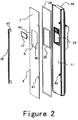
Figure 2 shows a schematic exploded view of a door of the refrigerator according to the preferred embodiment of the present invention; -
Figure 3 shows a partially sectional view of the door of the refrigerator according to the preferred embodiment of the present invention; -
Figure 4 shows a detailed view of the part "A" infigure 3 ; and -
Figure 5 shows a schematic front view of the refrigerator according to the preferred embodiment of the present invention. - Refer to figures, especially
figure 1 . Arefrigerator 1 comprises arefrigerator body 18. In this embodiment, therefrigerator body 18 defines a freezing compartment (not shown) and a refrigerating compartment (not shown) which are arranged side-by-side. The refrigerator further comprises a freezingcompartment door 2 and a refrigerating compartment door 2' which are connected to therefrigerator body 18. The freezingcompartment door 2 and the refrigerating compartment door 2' each are pivotally connected to a corresponding side of therefrigerator body 18 such that the freezing compartment and the refrigerating compartment can be opened or closed selectively. The freezingcompartment door 2 and the refrigerating compartment door 2' each are provided with ahandle 19 thereon such that a user can easily open or close the corresponding door. - The freezing
compartment door 2 is provided with adispenser 3. Thedispenser 3 is provided so that ice and/or water stored in therefrigerator 1 can be discharged even in case of the freezingcompartment door 2 being not opened. However, the present invention is not limited to this. For instance, in an alternative embodiment, it is also possible that thedispenser 3 is provided on the refrigerating compartment door 2'. - In this embodiment, the
dispenser 3 has a dispensingchamber 4 which is opened at its front end to receive an additional device such as a cup. Thedispenser 4 is recessed backwards at a depth from the front surface of the freezingcompartment door 2. - The
refrigerator 1 comprises acontrol panel 17 arranged on thedoor 2. In this embodiment, thecontrol panel 17 is arranged directly adjacent to and above the dispensingchamber 4. Preferably, thecontrol panel 17 comprises adisplay screen 20 and a plurality ofswitch devices 21. Thedisplay screen 20 is used to display information such as operating status and/or setting parameter of therefrigerator 1. Preferably, theswitch devices 21 are located below thedisplay screen 20 such that theswitch devices 21 are closer to the dispensingchamber 4 than thedisplay screen 21. In this embodiment, for example, by means of manipulation of a corresponding one of theswitch devices 21, a user can carry out operations such as water dispensing, flake ice dispensing and ice cake dispensing and can turn on a lighting device for illuminating the dispensingchamber 4. - As shown in
figures 2 and3 , the freezingcompartment door 2 comprises afirst wall 10 forming a back surface of the freezingcompartment door 2 and afront panel 5 forming a front surface of the freezingcompartment door 2. Thefirst wall 10 faces toward the freezing compartment when the freezingcompartment door 2 is closed. The freezingcompartment door 2 further comprises asecond wall 11 located between thefirst wall 10 and thefront panel 5. Thesecond wall 11 is preferably made of metallic sheet. - There is an interval between the
second wall 11 and thefirst wall 10 such that a space is formed between thesecond wall 11 and thefirst wall 10 to accommodate a thermally insulatedlayer 12. The thermally insulatedlayer 12 is preferably formed by foaming of thermally insulated foam material. - The
dispenser 3 comprises adispenser housing 26, which dispenser housing defines aconcave chamber 27 recessed in a front and back direction. The front end opening of theconcave chamber 27 is in a substantially quadrangle shape. Thesecond wall 11 is provided with anopening 23 corresponding with theconcave chamber 27. The position and the size of theopening 23 substantially correspond to those of the front end opening of theconcave chamber 27. - The
concave chamber 27 is divided into an upper portion and a lower portion by apartition wall 28. More particularly, a portion of theconcave chamber 27 which is below thepartition wall 28 is opened at its front end such that a dispensingchamber 4 is formed to receive an additional device. A portion of theconcave chamber 27 which is above thepartition wall 28 is closed by thecontrol panel 17. An ice discharging opening 30 is provided on thepartition wall 28 such that ice stored in the freezing compartment is entered into the portion of theconcave chamber 27 which is above thepartition wall 28 via anice transporting chute 29 and then is entered into the dispensingchamber 4 via the ice discharging opening 30. When it is not necessary to transport ice, theice transporting passage 29 is closed by aclosure element 44. - As shown in
figure 4 , thedispenser housing 26 comprises a mountingedge 31 which is matably attached to thesecond wall 11. Preferably, the front surface of the mountingedge 31 is pressed against the inner surface of thesecond wall 11 along theopening 23. Preferably, a sealing device is provided between the front surface of the mountingedge 31 and the rear surface of thesecond wall 11 so as to prevent foam material from escaping during foaming. Such a sealing device is preferably formed by adhesive tape, which facilitates thedispenser housing 26 being secured on the inner surface of thesecond wall 11. Thedispenser housing 26 comprises a connectingslot 32 arranged around theconcave chamber 27. Correspondingly, thesecond wall 11 comprises a connectingflange 32 extending backwards from the edge of theopening 23. The connectingflange 33 is inserted into the connectingslot 32 such that thedispenser housing 26 is secured on thesecond wall 11. Thedispenser housing 26 does not project beyond the front side of thesecond wall 11, and thus partially overlaps with the front surface of thesecond wall 11. Thefront panel 5 can be tightly pressed against the front side of thesecond wall 11. Thefront panel 5 is explained as follow. - The
front panel 5 is made of tempered glass and comprises a through-hole 6 adapted for thedispenser 3. The size and the position of the through-hole 6 substantially correspond to those of the front end opening of theconcave chamber 27. In this embodiment, the upper portion of the through-hole 6 is closed by thecontrol panel 17, and the lower portion of the through-hole 6 is constructed as an access to the dispensingchamber 4. - The
front panel 5 is preferably bonded to the front surface of thesecond wall 11 by means of adhesive means, which specially facilitates the front surface of thefront wall 5 being completely exposed outwards. Preferably, the adhesive means is a double-face adhesive tape which can implement strong adhesion. In this embodiment, the adhesive means comprises a fistadhesive section 24 arranged at the peripheral edge of thefront panel 5 and a secondadhesive section 25 arranged along the edge region of the through-hole 6. The firstadhesive section 24 and the secondadhesive section 25 each comprise a plurality of bar-shaped adhesive tapes which preferably adhere with each other to form a closed-loop adhesive frame, which can prevent foreign matter such as dust from entering between thefront panel 5 and thesecond wall 11. - With respect to the through-
hole 6, thefront panel 5 is divided into anupper region 7 above the through-hole 6, alower region 8 below the through-hole 6 andside regions hole 6 and which connects with theupper region 7 and thelower region 8. - The
front panel 5 has an outline in oblong shape. Preferably, the widths of theupper region 7 and thelower region 8 are at least substantially identical with the width of the freezingcompartment 2. The sum of the longitudinal lengths of thelower region 7, theupper region 8 and one of theside regions door 2 in value. Therefore, the front surface of thesecond wall 11 can be completely covered by thefront panel 5. - The
front panel 5 has a one-pieced structure such that theupper region 7, thelower region 8 and theside regions - The lateral width of the through-
hole 6 is at least a half of the width of thefront panel 5. Preferably, theside regions front panel 5. In order to ensure that thefront panel 5 has a sufficient strength, the lateral sizes of theside regions front panel 5 is 40 cm, the width of the through-hole 6 is 24 cm, the width of each of theside regions side regions -
Small holes 41 are provided on thefront panel 5 to mount ahandle 19 therein. A front end of ahandle mounting portion 42 secured on thesecond wall 11 projects into a corresponding one of thesmall holes 41 so as to be connected with a connectingroot 43 of thehandle 19. - As shown in
figures 3 and 4 , agap 13 is formed between thefront panel 5 and thesecond wall 11 in a front and back direction. The interval in the front and back direction of thegap 13 is substantially identical to the thickness of each of the fistadhesive section 24 after being pressed and the secondadhesive section 25 after being pressed. In this embodiment, thegap 13 is about 1 mm in size. - In an preferred embodiment according to the present invention, the end of a
chamber wall 15 of thedispenser housing 26 for defining theconcave chamber 27 extends beyond thesecond wall 11 and projects into the through-hole 6 such that the end of thechamber wall 15 forms ashelter element 14 used to isolate thesecond wall 11 and the gap 13from theconcave chamber 27. Since the dispensingchamber 4 is formed of a portion of theconcave chamber 27, thesecond wall 11 and thegap 13 are not exposed in the dispensingchamber 4. Preferably, the dispensingchamber wall 15 extends into the through-hole 6 and not beyond the front surface of thefront panel 5. -
Figure 5 shows a schematic perspective view of a refrigerator 1' according to another embodiment of the present invention. As shown infigure 5 , the refrigerator 1' comprises a refrigeratingcompartment door 34 which is provided with a table-formingopening 35. The table-formingopening 35 is provided through the refrigeratingcompartment door 34 in a front and back direction. The table-formingopening 35 is selectively closed or opened by a table-formingdoor 16 provided on therefrigerating compartment door 34. - The front surface of the refrigerating
compartment door 34 is formed by afront panel 36. Thefront panel 36 is made of glass and has a one-pieced structure. At a location corresponding to the table-formingopening 35, a through-hole 37 is formed on thefront panel 36 and its position and size substantially correspond to those of the table-formingopening 35. The lateral width of the through-hole 37 is larger than a half of the total width of thefront panel 36. Thefront panel 36 comprises anupper region 38 above the through-hole 36, alower region 39 below the through-hole 37 andside regions hole 36 and which connect with theupper region 38 and thelower region 39. Therefore, the front surface of the refrigeratingcompartment door 34 which comprises the surrounding area of the table-formingopening 35 can be made of only a piece of glass panel. This facilitates to solve the technical problem that material is not unified and connect seams are excessive in a case that the refrigeratingcompartment door 34 provided with the table-formingdoor 16 is made of glass panel.
Claims (15)
- A refrigerator (1) comprising a door (2) and a dispenser (3) mounted on the door (2), the door (2) comprising a front panel (5) forming at least a part of the door's front surface, the front panel (5) having a through-hole (6) at least partially corresponding to the dispenser (3), characterized in that the front panel (5) is a glass plate and comprises an upper region (7) above the through-hole (6), a lower region (8) below the through-hole (6) and side regions (9a, 9b) which are located between the upper region (7) and the lower region (8) and which connect with the upper region (7) and the lower region (8).
- The refrigerator (1) according to claim 1, characterized in that the front panel (5) has a one-pieced structure and/or that the front surface of the door (2) is substantially formed by the front panel (5).
- The refrigerator (1) according to claim 1 or 2, characterized in that the sum of the longitudinal lengths of the upper region (7), the lower region (8) and one of the side regions (9a, 9b) is substantially equal to the longitudinal height of the door (2) in value and/or that the lateral size of each of the side regions (9a, 9b) is at least 5 cm, for example 7 to 8 cm.
- The refrigerator (1) according to any one of the previous claims, characterized in that the door (2) comprises a first wall (10) forming a back surface of the door (2), a second wall (11) which is separated at a predetermined interval from the first wall (10) and a thermally insulated layer (12) accommodated between the first wall (10) and the second wall (11), and the front panel (5) is attached at the front side of the second wall (11).
- The refrigerator (1) according to claim 4, characterized in that a gap (13) is formed in a front and back direction between the front panel (5) and the second wall (11), and the door (2) comprises a shelter element (14) for shielding the gap (13) along the through-hole (6).
- The refrigerator (1) according to claim 5, characterized in that the dispenser (3) comprises a dispenser housing (26), and the shelter element (14) is formed by the dispenser housing (26), whereas preferably the dispenser housing (26) defines a concave chamber (27).
- The refrigerator (1) according to claim 6, characterized in that the dispenser housing (26) comprises a mounting edge (31) which is matably attached to the second wall (11), preferably the front surface of the mounting edge (31) is pressed against the inner surface of the second wall (11) along the opening (23).
- The refrigerator (1) according to claim 7, characterized in that a sealing device is provided between the front surface of the mounting edge (31) and the rear surface of the second wall (11).
- The refrigerator (1) according to at least one of the claims 6 - 8, characterized in that the dispenser housing (26) comprises a connecting slot (32) arranged around the concave chamber (27) and correspondingly the second wall (11) comprises a connecting flange (33) extending backwards from the edge of the opening (23).
- The refrigerator (1) according to claim 9, characterized in that the connecting flange (33) is inserted into the connecting slot (32) such that the dispenser housing (26) is secured on the second wall (11).
- The refrigerator (1) according to at least one of the claims 6 - 10, characterized in that the dispenser housing (26) does project beyond the front side of the second wall (11) and partially overlaps with the front surface of the second wall (11).
- The refrigerator (1) according to at least one of the claims 6 - 11, characterized in that an end of a chamber wall (15) of the dispenser housing (26) for defining the concave chamber (27) extends beyond the second wall (11) and projects into the through-hole (6) such that the end of the chamber wall (15) forms the shelter element (14) used to isolate the second wall (11) and the gap (13) from the concave chamber (27).
- The refrigerator (1) according to claim 12, characterized in that the chamber wall (15) extends into the through-hole (6) and not beyond the front surface of the front panel (5).
- The refrigerator (1) according to any one of the previous claims, characterized in that the dispenser (3) comprises a dispensing chamber (4) for accommodating at least a part of an additional device, and a chamber wall (15) for defining the dispensing chamber (4) extends forwards into the through-hole (6).
- The refrigerator (1) according to claim 14, characterized in that the chamber wall (15) extending into the through-hole shields the end face of the second wall (11) and the gap (13) between the second wall (11) and the front panel (5).
Applications Claiming Priority (2)
| Application Number | Priority Date | Filing Date | Title |
|---|---|---|---|
| CN200910028341.9A CN101776364B (en) | 2009-01-08 | 2009-01-08 | Refrigerator |
| EP09796758.2A EP2386049B1 (en) | 2009-01-08 | 2009-12-30 | Refrigerator |
Related Parent Applications (2)
| Application Number | Title | Priority Date | Filing Date |
|---|---|---|---|
| EP09796758.2A Division EP2386049B1 (en) | 2009-01-08 | 2009-12-30 | Refrigerator |
| EP09796758.2A Division-Into EP2386049B1 (en) | 2009-01-08 | 2009-12-30 | Refrigerator |
Publications (1)
| Publication Number | Publication Date |
|---|---|
| EP3056844A1 true EP3056844A1 (en) | 2016-08-17 |
Family
ID=42316898
Family Applications (2)
| Application Number | Title | Priority Date | Filing Date |
|---|---|---|---|
| EP16155000.9A Withdrawn EP3056844A1 (en) | 2009-01-08 | 2009-12-30 | Refrigerator |
| EP09796758.2A Active EP2386049B1 (en) | 2009-01-08 | 2009-12-30 | Refrigerator |
Family Applications After (1)
| Application Number | Title | Priority Date | Filing Date |
|---|---|---|---|
| EP09796758.2A Active EP2386049B1 (en) | 2009-01-08 | 2009-12-30 | Refrigerator |
Country Status (5)
| Country | Link |
|---|---|
| US (1) | US20110239689A1 (en) |
| EP (2) | EP3056844A1 (en) |
| CN (1) | CN101776364B (en) |
| PL (1) | PL2386049T3 (en) |
| WO (1) | WO2010079111A2 (en) |
Families Citing this family (10)
| Publication number | Priority date | Publication date | Assignee | Title |
|---|---|---|---|---|
| CN102072609B (en) * | 2011-02-14 | 2012-11-28 | 合肥美的荣事达电冰箱有限公司 | Refrigerator door body and refrigerator having same |
| CN102213531B (en) * | 2011-05-30 | 2013-05-22 | 合肥美的荣事达电冰箱有限公司 | Refrigerator door, manufacture method thereof and refrigerator with refrigerator door |
| JP2013061133A (en) * | 2011-09-14 | 2013-04-04 | Sharp Corp | Refrigerator |
| JP2013061134A (en) * | 2011-09-14 | 2013-04-04 | Sharp Corp | Refrigerator |
| CN102706078A (en) * | 2012-06-12 | 2012-10-03 | 海尔集团公司 | Refrigerator door body equipped with bar counter |
| US9851137B2 (en) * | 2012-12-06 | 2017-12-26 | Whirlpool Corporation | Utility routing for a door-mounted icemaker |
| KR20150071441A (en) * | 2013-12-18 | 2015-06-26 | 삼성전자주식회사 | Refrigerator |
| CN104457121A (en) * | 2014-12-23 | 2015-03-25 | 合肥美的电冰箱有限公司 | Distributor and refrigerator |
| DE102016221211A1 (en) * | 2016-10-27 | 2018-05-03 | BSH Hausgeräte GmbH | Refrigeration device with beverage dispenser |
| US11150004B1 (en) * | 2020-08-03 | 2021-10-19 | Electrolux Home Products, Inc. | Integrated ice chute with dispenser housing |
Citations (5)
| Publication number | Priority date | Publication date | Assignee | Title |
|---|---|---|---|---|
| JPH05322436A (en) * | 1992-05-26 | 1993-12-07 | Matsushita Refrig Co Ltd | Heat insulating door |
| WO2005045334A1 (en) * | 2003-11-06 | 2005-05-19 | Matsushita Electric Industrial Co., Ltd. | Door, refrigerator using the same, and method of producing door |
| JP2005180790A (en) * | 2003-12-19 | 2005-07-07 | Sanyo Electric Co Ltd | Refrigerator |
| JP2006046793A (en) * | 2004-08-04 | 2006-02-16 | Matsushita Electric Ind Co Ltd | Refrigerator door |
| DE102005057161A1 (en) * | 2005-11-30 | 2007-05-31 | BSH Bosch und Siemens Hausgeräte GmbH | Refrigerating appliance has sleeve through which delivery device is accessible and which projects from front side and is encompassed by encircling frame which projects from sleeve |
Family Cites Families (7)
| Publication number | Priority date | Publication date | Assignee | Title |
|---|---|---|---|---|
| JPH05126461A (en) * | 1991-11-07 | 1993-05-21 | Matsushita Refrig Co Ltd | Thermal insulation door |
| KR100488074B1 (en) * | 2003-03-22 | 2005-05-06 | 엘지전자 주식회사 | Door structure of refrigerator |
| KR20050026740A (en) * | 2003-09-06 | 2005-03-16 | 엘지전자 주식회사 | Refrigerator with dispenser |
| KR100692221B1 (en) * | 2005-09-28 | 2007-03-09 | 삼성전자주식회사 | Refrigerator & Bucket For Refrigerator |
| CN2881490Y (en) * | 2006-01-18 | 2007-03-21 | 海尔集团公司 | Refrigerator distributor with lighting device |
| DE102006018204A1 (en) * | 2006-04-19 | 2007-10-25 | BSH Bosch und Siemens Hausgeräte GmbH | Refrigeration device with output device |
| ITVA20070001A1 (en) * | 2007-01-04 | 2008-07-05 | Whirlpool Co | RECESSED REFRIGERATOR PROVIDED WITH A WATER AND BEVERAGE DISPENSER |
-
2009
- 2009-01-08 CN CN200910028341.9A patent/CN101776364B/en active Active
- 2009-12-30 WO PCT/EP2009/068013 patent/WO2010079111A2/en not_active Ceased
- 2009-12-30 US US13/133,388 patent/US20110239689A1/en not_active Abandoned
- 2009-12-30 EP EP16155000.9A patent/EP3056844A1/en not_active Withdrawn
- 2009-12-30 EP EP09796758.2A patent/EP2386049B1/en active Active
- 2009-12-30 PL PL09796758.2T patent/PL2386049T3/en unknown
Patent Citations (5)
| Publication number | Priority date | Publication date | Assignee | Title |
|---|---|---|---|---|
| JPH05322436A (en) * | 1992-05-26 | 1993-12-07 | Matsushita Refrig Co Ltd | Heat insulating door |
| WO2005045334A1 (en) * | 2003-11-06 | 2005-05-19 | Matsushita Electric Industrial Co., Ltd. | Door, refrigerator using the same, and method of producing door |
| JP2005180790A (en) * | 2003-12-19 | 2005-07-07 | Sanyo Electric Co Ltd | Refrigerator |
| JP2006046793A (en) * | 2004-08-04 | 2006-02-16 | Matsushita Electric Ind Co Ltd | Refrigerator door |
| DE102005057161A1 (en) * | 2005-11-30 | 2007-05-31 | BSH Bosch und Siemens Hausgeräte GmbH | Refrigerating appliance has sleeve through which delivery device is accessible and which projects from front side and is encompassed by encircling frame which projects from sleeve |
Also Published As
| Publication number | Publication date |
|---|---|
| US20110239689A1 (en) | 2011-10-06 |
| CN101776364B (en) | 2014-12-31 |
| CN101776364A (en) | 2010-07-14 |
| WO2010079111A2 (en) | 2010-07-15 |
| WO2010079111A3 (en) | 2010-12-09 |
| EP2386049A2 (en) | 2011-11-16 |
| PL2386049T3 (en) | 2016-09-30 |
| EP2386049B1 (en) | 2016-05-04 |
Similar Documents
| Publication | Publication Date | Title |
|---|---|---|
| EP2386049B1 (en) | Refrigerator | |
| AU2021204974B2 (en) | Refrigerator | |
| US10907884B1 (en) | Door end closure assembly with integrated user interface | |
| CN105258437B (en) | Doors for refrigerators and refrigerators | |
| US9976795B2 (en) | Refrigerator | |
| CN105333680B (en) | refrigerator | |
| CN105466119B (en) | refrigerator with door | |
| CN104422237A (en) | Refrigerator and door of the same | |
| EP2348268B1 (en) | Refrigeration appliance and manufacturing method thereof | |
| US10627152B2 (en) | Domestic refrigeration appliance having an external housing of an icemaker and a frame at the front | |
| US10288342B2 (en) | Refrigerator door with a handle groove | |
| CN203501624U (en) | Door for refrigerator and refrigerator | |
| CN201548012U (en) | Refrigeration appliance | |
| EP2466231B1 (en) | Household appliance having ice water dispenser | |
| EP2975346A1 (en) | Refrigerator | |
| EP2373941B2 (en) | Refrigerator | |
| CN218220148U (en) | Door body mechanism of dish washing machine and dish washing machine | |
| CN102620504A (en) | Refrigerating appliance and method for manufacturing same | |
| CA2484872A1 (en) | Storage bin assembly for a refrigerator | |
| KR20170019775A (en) | Refrigerator |
Legal Events
| Date | Code | Title | Description |
|---|---|---|---|
| PUAI | Public reference made under article 153(3) epc to a published international application that has entered the european phase |
Free format text: ORIGINAL CODE: 0009012 |
|
| AC | Divisional application: reference to earlier application |
Ref document number: 2386049 Country of ref document: EP Kind code of ref document: P |
|
| AK | Designated contracting states |
Kind code of ref document: A1 Designated state(s): AT BE BG CH CY CZ DE DK EE ES FI FR GB GR HR HU IE IS IT LI LT LU LV MC MK MT NL NO PL PT RO SE SI SK SM TR |
|
| 17P | Request for examination filed |
Effective date: 20170217 |
|
| RBV | Designated contracting states (corrected) |
Designated state(s): AT BE BG CH CY CZ DE DK EE ES FI FR GB GR HR HU IE IS IT LI LT LU LV MC MK MT NL NO PL PT RO SE SI SK SM TR |
|
| 17Q | First examination report despatched |
Effective date: 20180404 |
|
| STAA | Information on the status of an ep patent application or granted ep patent |
Free format text: STATUS: THE APPLICATION HAS BEEN WITHDRAWN |
|
| 18W | Application withdrawn |
Effective date: 20181012 |