EP3056765A1 - Linear motion mechanism, adjusting valve drive device, and steam turbine - Google Patents
Linear motion mechanism, adjusting valve drive device, and steam turbine Download PDFInfo
- Publication number
- EP3056765A1 EP3056765A1 EP14873062.5A EP14873062A EP3056765A1 EP 3056765 A1 EP3056765 A1 EP 3056765A1 EP 14873062 A EP14873062 A EP 14873062A EP 3056765 A1 EP3056765 A1 EP 3056765A1
- Authority
- EP
- European Patent Office
- Prior art keywords
- nut
- ball screw
- cylinder rod
- grease
- grease supply
- Prior art date
- Legal status (The legal status is an assumption and is not a legal conclusion. Google has not performed a legal analysis and makes no representation as to the accuracy of the status listed.)
- Granted
Links
Images


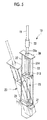


Classifications
-
- F—MECHANICAL ENGINEERING; LIGHTING; HEATING; WEAPONS; BLASTING
- F01—MACHINES OR ENGINES IN GENERAL; ENGINE PLANTS IN GENERAL; STEAM ENGINES
- F01D—NON-POSITIVE DISPLACEMENT MACHINES OR ENGINES, e.g. STEAM TURBINES
- F01D17/00—Regulating or controlling by varying flow
- F01D17/10—Final actuators
- F01D17/12—Final actuators arranged in stator parts
- F01D17/14—Final actuators arranged in stator parts varying effective cross-sectional area of nozzles or guide conduits
- F01D17/141—Final actuators arranged in stator parts varying effective cross-sectional area of nozzles or guide conduits by means of shiftable members or valves obturating part of the flow path
- F01D17/145—Final actuators arranged in stator parts varying effective cross-sectional area of nozzles or guide conduits by means of shiftable members or valves obturating part of the flow path by means of valves, e.g. for steam turbines
-
- F—MECHANICAL ENGINEERING; LIGHTING; HEATING; WEAPONS; BLASTING
- F01—MACHINES OR ENGINES IN GENERAL; ENGINE PLANTS IN GENERAL; STEAM ENGINES
- F01D—NON-POSITIVE DISPLACEMENT MACHINES OR ENGINES, e.g. STEAM TURBINES
- F01D25/00—Component parts, details, or accessories, not provided for in, or of interest apart from, other groups
- F01D25/24—Casings; Casing parts, e.g. diaphragms, casing fastenings
-
- F—MECHANICAL ENGINEERING; LIGHTING; HEATING; WEAPONS; BLASTING
- F01—MACHINES OR ENGINES IN GENERAL; ENGINE PLANTS IN GENERAL; STEAM ENGINES
- F01D—NON-POSITIVE DISPLACEMENT MACHINES OR ENGINES, e.g. STEAM TURBINES
- F01D5/00—Blades; Blade-carrying members; Heating, heat-insulating, cooling or antivibration means on the blades or the members
- F01D5/02—Blade-carrying members, e.g. rotors
-
- F—MECHANICAL ENGINEERING; LIGHTING; HEATING; WEAPONS; BLASTING
- F01—MACHINES OR ENGINES IN GENERAL; ENGINE PLANTS IN GENERAL; STEAM ENGINES
- F01D—NON-POSITIVE DISPLACEMENT MACHINES OR ENGINES, e.g. STEAM TURBINES
- F01D5/00—Blades; Blade-carrying members; Heating, heat-insulating, cooling or antivibration means on the blades or the members
- F01D5/12—Blades
-
- F—MECHANICAL ENGINEERING; LIGHTING; HEATING; WEAPONS; BLASTING
- F16—ENGINEERING ELEMENTS AND UNITS; GENERAL MEASURES FOR PRODUCING AND MAINTAINING EFFECTIVE FUNCTIONING OF MACHINES OR INSTALLATIONS; THERMAL INSULATION IN GENERAL
- F16H—GEARING
- F16H57/00—General details of gearing
- F16H57/04—Features relating to lubrication or cooling or heating
- F16H57/048—Type of gearings to be lubricated, cooled or heated
- F16H57/0497—Screw mechanisms
-
- F—MECHANICAL ENGINEERING; LIGHTING; HEATING; WEAPONS; BLASTING
- F16—ENGINEERING ELEMENTS AND UNITS; GENERAL MEASURES FOR PRODUCING AND MAINTAINING EFFECTIVE FUNCTIONING OF MACHINES OR INSTALLATIONS; THERMAL INSULATION IN GENERAL
- F16K—VALVES; TAPS; COCKS; ACTUATING-FLOATS; DEVICES FOR VENTING OR AERATING
- F16K31/00—Actuating devices; Operating means; Releasing devices
- F16K31/02—Actuating devices; Operating means; Releasing devices electric; magnetic
- F16K31/04—Actuating devices; Operating means; Releasing devices electric; magnetic using a motor
- F16K31/047—Actuating devices; Operating means; Releasing devices electric; magnetic using a motor characterised by mechanical means between the motor and the valve, e.g. lost motion means reducing backlash, clutches, brakes or return means
-
- F—MECHANICAL ENGINEERING; LIGHTING; HEATING; WEAPONS; BLASTING
- F05—INDEXING SCHEMES RELATING TO ENGINES OR PUMPS IN VARIOUS SUBCLASSES OF CLASSES F01-F04
- F05D—INDEXING SCHEME FOR ASPECTS RELATING TO NON-POSITIVE-DISPLACEMENT MACHINES OR ENGINES, GAS-TURBINES OR JET-PROPULSION PLANTS
- F05D2220/00—Application
- F05D2220/30—Application in turbines
- F05D2220/31—Application in turbines in steam turbines
-
- F—MECHANICAL ENGINEERING; LIGHTING; HEATING; WEAPONS; BLASTING
- F05—INDEXING SCHEMES RELATING TO ENGINES OR PUMPS IN VARIOUS SUBCLASSES OF CLASSES F01-F04
- F05D—INDEXING SCHEME FOR ASPECTS RELATING TO NON-POSITIVE-DISPLACEMENT MACHINES OR ENGINES, GAS-TURBINES OR JET-PROPULSION PLANTS
- F05D2260/00—Function
- F05D2260/50—Kinematic linkage, i.e. transmission of position
- F05D2260/57—Kinematic linkage, i.e. transmission of position using servos, independent actuators, etc.
-
- F—MECHANICAL ENGINEERING; LIGHTING; HEATING; WEAPONS; BLASTING
- F05—INDEXING SCHEMES RELATING TO ENGINES OR PUMPS IN VARIOUS SUBCLASSES OF CLASSES F01-F04
- F05D—INDEXING SCHEME FOR ASPECTS RELATING TO NON-POSITIVE-DISPLACEMENT MACHINES OR ENGINES, GAS-TURBINES OR JET-PROPULSION PLANTS
- F05D2270/00—Control
- F05D2270/50—Control logic embodiments
- F05D2270/58—Control logic embodiments by mechanical means, e.g. levers, gears or cams
-
- F—MECHANICAL ENGINEERING; LIGHTING; HEATING; WEAPONS; BLASTING
- F05—INDEXING SCHEMES RELATING TO ENGINES OR PUMPS IN VARIOUS SUBCLASSES OF CLASSES F01-F04
- F05D—INDEXING SCHEME FOR ASPECTS RELATING TO NON-POSITIVE-DISPLACEMENT MACHINES OR ENGINES, GAS-TURBINES OR JET-PROPULSION PLANTS
- F05D2270/00—Control
- F05D2270/60—Control system actuates means
- F05D2270/62—Electrical actuators
-
- F—MECHANICAL ENGINEERING; LIGHTING; HEATING; WEAPONS; BLASTING
- F16—ENGINEERING ELEMENTS AND UNITS; GENERAL MEASURES FOR PRODUCING AND MAINTAINING EFFECTIVE FUNCTIONING OF MACHINES OR INSTALLATIONS; THERMAL INSULATION IN GENERAL
- F16H—GEARING
- F16H25/00—Gearings comprising primarily only cams, cam-followers and screw-and-nut mechanisms
- F16H25/18—Gearings comprising primarily only cams, cam-followers and screw-and-nut mechanisms for conveying or interconverting oscillating or reciprocating motions
- F16H25/20—Screw mechanisms
- F16H25/22—Screw mechanisms with balls, rollers, or similar members between the co-operating parts; Elements essential to the use of such members
- F16H25/2204—Screw mechanisms with balls, rollers, or similar members between the co-operating parts; Elements essential to the use of such members with balls
Definitions
- the present invention relates to a linear motion mechanism, and a governing valve drive device and a steam turbine which use the linear motion mechanism.
- a steam turbine is used so as to drive a machine or the like, and includes a turbine main body having a rotor which is rotatably supported. The rotor is rotationally driven by supplying steam serving as a working fluid to the turbine main body. Steam supplied to the turbine main body or steam extracted from the turbine main body flows through a steam channel of the steam turbine. A governing valve is provided in the steam channel. By adjusting an opening degree of the governing valve, it is possible to adjust a flow rate of the steam supplied to the turbine main body.
- the governing valve is driven by an governing valve drive device.
- PTL 1 discloses a governing valve drive device which includes an electric motor, and a switching mechanism such as a ball screw or the like which converts a rotary motion of the electric motor into a linear motion of a governing valve.
- the ball screw includes a meshing portion having a contact angle in a spiral screw groove, if opening and closing operations of the governing valve are repeated for a long period, there is a problem that only a specific portion of the meshing portion of the ball screw is abraded.
- PTL 2 discloses a configuration in which grease is supplied to a ball screw nut, into which a ball screw shaft having screw grooves formed on the outer circumference surface is screwed, from the outside.
- PTL 3 disclose a configuration in which a ball screw is accommodated in a tubular housing and a grease supply pipeline for supplying grease to a ball screw nut screwed into a ball screw shaft from the outside is provided.
- the grease supply pipeline is provided inside a stator of an electric motor for rotationally driving the ball screw and integrally rotates with a rotor.
- the present invention is made in consideration of the above-described circumstances, and an object thereof is to provide a linear motion mechanism, a governing valve drive device, and a steam turbine capable of easily supplying grease and obtaining high reliability regardless of the drive type of the ball screw.
- the present invention adopts the following means to achieve the above-described object.
- the linear motion mechanism the governing valve drive device, and the steam turbine according to the present invention, it is possible to supply grease to the linear motion mechanism from the outside of the casing. Accordingly, it is possible to easily supply grease regardless of the drive type of the ball screw. As a result, it is possible to easily and reliably perform maintenance of the ball screw, and it is possible to obtain high reliability.
- Fig. 1 is a schematic view showing the entire configuration of a steam turbine 10 according to an embodiment of the present invention.
- the steam turbine 10 of the present embodiment includes a turbine main body 11, a steam channel 12 through which steam serving as a working fluid flows, a governing valve 13, a lever member 14, a governing valve drive device 15, and an electronic governor 17 which controls the governing valve drive device 15.
- the turbine main body 11 includes a tubular casing 111, a bearing 112 which is provided in the casing 111, a rotor 113 which is rotatably supported by the bearing 112 and is disposed inside the casing 111, and a speed detection sensor 114 which detects a rotating speed of the rotor 113.
- the rotor 113 includes a rotary shaft 115, and a plurality of blades 116 which are fixed to the rotary shaft 115.
- the blades 116 configured as described above are rotated by steam, and a compressor 18 is driven by the rotating force.
- the steam channel 12 is a channel which supplies steam serving as a working fluid to the turbine main body 11.
- Steam is introduced from a steam inlet port 121 on one end side of the steam channel 12.
- a steam supply port 122 on the other end side of the steam channel 12 is connected to the turbine main body 11.
- a throttle hole 123 in which the width of the channel is narrowed is provided between the steam inlet port 121 and the steam supply port 122.
- the steam channel 12 may be a channel through which steam extracted from the turbine main body 11 flows.
- the governing valve 13 adjusts an amount of the steam which is supplied to the turbine main body 11.
- the governing valve 13 includes a rod-shaped arm member 131, and an approximately hemispherical sealing member (valve element) 132 which is provided on the tip section of the arm member 131.
- a base end section of the arm member 131 is rotatably attached to an intermediate portion in a longitudinal direction of the lever member 14. Since the governing valve 13 has the above-described configuration, the arm member 131 linearly moves along the steam channel 12, and the sealing member 132 on the tip section of the arm member 131 is fitted to or separated from (in other words, opens and closes) the throttle hole 123 of the steam channel 12. Accordingly, a size of an opening between the throttle hole 123 and the sealing member 132 is changed. Therefore, a flow rate of the steam which is supplied to the turbine main body 11 via the throttle hole 123 is changed.
- the lever member 14 is a member which transmits output of the governing valve drive device 15 to the governing valve 13 and causes the sealing member 132 to advance toward and to retreat from the steam channel 12.
- a base end section (right end section in Fig. 1 ) in the longitudinal direction of the lever member 14 is rotatably supported.
- One end section of a lever-side rod 19 is rotatably attached to the tip section in the longitudinal direction of the lever member 14.
- a base end section of the arm member 131 configuring the governing valve 13 is rotatably attached to the intermediate portion in the longitudinal direction of the lever member 14.
- one end of a pull spring 20 is attached to the further tip side in the longitudinal direction of the lever member 14 relative to the attachment position of the arm member 131.
- the pull spring 20 functions as forcibly closing means for forcibly closing the governing valve 13.
- the other end of the pull spring 20 is fixed to a frame (not shown) of the steam channel 12 or the like so as to be immovable. That is, in a state where an external force is not applied to the pull spring 20, a tensile force which rotates the lever member 14 in the counterclockwise direction in Fig. 1 is applied to the lever member 14.
- the governing valve drive device 15 is a mechanism which drives the above-described governing valve 13.
- the governing valve drive device 15 includes an electric actuator 23.
- the electric actuator 23 includes a pair of brackets 21 which is installed so as to be fixed to a pedestal or the like, and a holding member 22 which is rotatably supported by the brackets 21. The electric actuator 23 is held by the holding member 22.
- Fig. 2 is a perspective view showing the vicinity of the governing valve drive device 15.
- Each of the pair of brackets 21 has an approximately L-shaped section.
- the pair of the brackets 21 is fixed to pedestals 25.
- the pedestals 25 are provided so as to be close to a bearing cover 24.
- the bearing 112 which rotatably supports the rotary shaft 115 of the rotor 113 shown in Fig. 1 is accommodated in the bearing cover 24.
- the holding member 22 has an approximately U shape in a side view. Both end sections of the approximately U shape of the holding member 22 are rotatably supported by the above-described pair of brackets 21.
- Figs. 3A and 3B are sectional views showing the internal configuration of the electric actuator 23.
- Fig. 4 is an enlarged main section view showing a configuration of a grease supply mechanism of a ball screw mechanism 27.
- the electric actuator 23 includes the ball screw mechanism (linear motion mechanism) 27 and a brake 28.
- the ball screw mechanism 27 is a mechanism which converts rotary motion of an electric motor 26 into linear motion of the lever-side rod 19.
- the ball screw mechanism 27 includes the electric motor 26, a ball screw 30 which is connected to a drive shaft of the electric motor 26 and is rotationally driven around an axis by the electric motor 26, and a piston unit 31 which advances and retreats relative to the ball screw 30 in the axial direction of the ball screw 30 according to the rotation of the ball screw 30.
- the electric motor 26 is accommodated in a motor accommodation portion 29.
- the motor accommodation portion 29 is provided on the base end section of the electric actuator 23, and the inner portion thereof is closed. Accordingly, the electric motor 26 has an explosion-proof structure which is isolated from oil existing in the vicinity of the electric motor 26.
- the ball screw 30 is a long screw member, and a female screw grooves 30m are formed on the outer circumference surface of the ball screw 30.
- One end section of the ball screw 30 is connected to the drive shaft of the electric motor 26.
- the ball screw 30 is rotationally driven by the rotation of the electric motor 26.
- the electric actuator 23 includes the brake 28 which is provided at a position on the side opposite to the ball screw 30 in a state where the electric motor 26 is interposed therebetween.
- the brake 28 is constituted of an electromagnetic disk brake. The brake 28 is operated when supply of power is cut off to stop the rotation of the electric motor 26.
- the operation of the brake 28 is controlled by the electronic governor 17 (refer to Fig. 1 ).
- the electronic governor 17 operates the brake 28. That is, the rotation of the electric motor 26 is stopped by operating the brake 28.
- the piston unit 31 reciprocates along the ball screw 30.
- the piston unit 31 includes a nut 311, a cylinder rod 312, a rod end connector 313, and an actuator-side rod 314.
- the nut 311 is an approximately annular member which is screwed into the ball screw 30. As shown in Fig. 4 , female screw grooves 311m are formed on the inner circumference surface of the nut 311.
- a plurality of balls 316 are interposed between the female screw grooves 311m on the inner circumferential surface of the nut 311 and the female screw grooves 30m on the outer circumferential surface of the ball screw 30. Since the balls 316 roll between the female screw grooves 311m and the female screw grooves 30m, the nut 311 and the ball screw 30 are relatively displaced along a center axis C direction while the nut 311 and the ball screw 30 relatively rotate around the center axis C of the ball screw 30.
- a circulation path 317 for circulating the balls 316 between one end side and the other end side of the nut 311 is formed inside the nut 311. Both end sections 317a and 317b of the circulation path 317 open to the inner circumferential surface of the nut 311 on one end side and the other end side of the nut 311.
- the cylinder rod 312 is formed in a tubular shape so as to cover the outside of the ball screw 30 such that the ball screw 30 can insert into the inner portion of the cylinder rod 312.
- a flanged portion 312f which expands toward the outer circumferential side is formed on the base end section of the cylinder rod 312.
- the cylinder rod 312 is fixed to one end surface 311f of the nut 311 by bolts 315 at a plurality of locations in the circumferential direction of the flanged portion 312f.
- the rod end connector 313 is a member which is mounted on the tip section of the cylinder rod 312.
- a female screw is formed on the inner circumferential surface on the tip side of the rod end connector 313.
- the actuator-side rod 314 is a member which extends in the extension direction of the cylinder rod 312.
- a male screw is formed on one end section in the longitudinal direction of the actuator-side rod 314.
- the male screw of the actuator-side rod 314 is screwed into the female screw of the rod end connector 313 and is fixed to the rod end connector 313.
- the ball screw 30 and the nut 311 are surrounded by a piston casing (casing) 36.
- the outer circumferential surface of the nut 311 is fixed to the inner circumferential surface of the piston casing 36, and the rotation of the nut 311 around the center axis C is restricted.
- the piston casing 36 includes a piston cap 37 which seals the piston casing 36 on the upper end (left ends in Figs. 3A and 3B ).
- a through hole 37h is formed in the piston cap 37, and the cylinder rod 312 protrudes and retracts through the through hole 37h. At this time, a tip section 312a of the cylinder rod 312 is always exposed to the outside from the piston casing 36 and the piston cap 37.
- the piston unit 31 has the above-described configuration, if the ball screw 30 is rotationally driven around the axis by the electric motor 26, as shown in Fig. 3B , the nut 311 screwed into the ball screw 30 moves in the direction along the rotation direction of the ball screw 30 along the axis. According to the movement of the nut 311, the cylinder rod 312 which is fixed to the nut 311, the rod end connector 313, and the actuator-side rod 314 also moves in the axis of the ball screw 30 along with the nut 311.
- Fig. 5 is a perspective view showing the vicinity of the electric actuator 23.
- the electric actuator 23 is fixed to the holding member 22.
- the actuator-side rod 314 is inserted into a through hole 39a of a guide plate 39 which is provided on the upper end section of the holding member 22.
- the actuator-side rod 314 is connected to the lever-side rod 19.
- the holding member 22 can rotate with a location supported by the bracket 21 as a supporting point according to the swing of the lever member 14.
- the electronic governor 17 controls the operation of the governing valve drive device 15.
- results in which a process control is performed based on a detection result of a pressure or a temperature in the compressor 18, are input to the electronic governor 17.
- the rotating speed of the blade 116 which is detected by the speed detection sensor 114 configuring the turbine main body 11 is input to the electronic governor 17.
- instruction from a user input from an operation board 34 is input to the electronic governor 17.
- the electronic governor 17 controls the operation of the governing valve drive device 15 based on each input. More specifically, the electronic governor 17 controls the operation of the electric motor 26 configuring the electric actuator 23 based on each input. Accordingly, the governing valve 13 is driven by the electric actuator 23.
- a nut-side grease supply hole 321 formed in the nut 311 and a cylinder rod-side grease supply hole 322 formed in the cylinder rod 312 are provided.
- the nut-side grease supply hole 321 includes a discharge port 323 on one end, and the discharge port 323 opens toward the outer circumferential surface of the ball screw 30 on the inner circumferential surface of the nut 311.
- the nut-side grease supply hole 321 extends in the direction along the center axis C, and the other end 321b opens to the one end surface 311f of the nut 311.
- the cylinder rod-side grease supply hole 322 includes an inlet 324 on one end, and the inlet 324 opens to the outer circumferential surface of the cylinder rod 312.
- the inlet 324 is formed at a position which is always exposed to the outside of the piston casing 36 in the cylinder rod 312.
- the other end 322b of the cylinder rod-side grease supply hole 322 opens to the flanged portion 312f of the cylinder rod 312, and communicates with the nut-side grease supply hole 321. That is, the opening on the other end 322b of the cylinder rod-side grease supply hole 322 and the opening on the other end 321b of the nut-side grease supply hole 321 are connected so as to face each other. Accordingly, the cylinder rod-side grease supply hole 322 and the nut-side grease supply hole 321 communicate with each other.
- annular seal member 325 is interposed between the flanged portion 312f and the one end surface 311f of the nut 311, and seals the vicinity of the connection portion between the cylinder rod-side grease supply hole 322 and the nut-side grease supply hole 321.
- the cylinder rod-side grease supply hole 322 communicating with the nut-side grease supply hole 321 is provided in the cylinder rod 312, and the inlet 324 through which the grease is injected to the cylinder rod-side grease supply hole 322 is formed at the position exposed to the outside of the piston casing 36. Accordingly, in the ball screw mechanism 27 in which the ball screw 30 and the nut 311 are accommodated in the piston casing 36, it is possible to supply grease from the outside of the piston casing 36. As a result, it is possible to easily and reliably perform maintenance of the ball screw 30, and it is possible to increase reliability of the ball screw mechanism 27, and the governing valve drive device 15 and the steam turbine 10 including the ball screw mechanism 27.
- Fig. 6 is an enlarged main sectional view showing the configuration of the grease supply mechanism of the ball screw mechanism 27 of the steam turbine 10 in the second embodiment.
- the nut-side grease supply hole 321 which is formed in the nut 311 and the cylinder rod-side grease supply hole 322 which is formed in the cylinder rod 312 are provided.
- a grease supply pipe 341 having flexibility formed of a rubber-based material, a soft resin-based material, a flexible metal pipe, or the like is connected to the inlet 324 of the cylinder rod-side grease supply hole 322.
- a grease supply device 342 which supplies grease from the outside is connected to the grease supply pipe 341.
- the grease supply device 342 can supply grease to the inlet 324 through the grease supply pipe 341 every predetermined operation time or the like.
- Fig. 7 is an enlarged main sectional view showing the configuration of the grease supply mechanism of the ball screw mechanism 27 of the steam turbine 10 in the third embodiment.
- the nut-side grease supply hole 321 which is formed in the nut 311 and the cylinder rod-side grease supply hole 322 which is formed in the cylinder rod 312 are provided.
- the grease supply pipe 341 is connected to the inlet 324 of the cylinder rod-side grease supply hole 322.
- the grease supply device 342 which supplies grease from the outside is connected to the grease supply pipe 341.
- a nut-side discharge hole 331 which is formed in the nut 311 and a cylinder rod-side discharge hole 332 which is formed in the cylinder rod 312 are formed.
- the nut-side discharge hole 331 has an inflow port 333 on one end, and the inflow port 333 opens toward the outer circumferential surface of the ball screw 30 at a position different from the opening position of the discharge port 323 on the one end of the nut-side grease supply hole 321.
- the inflow port 333 is formed further outside of the nut 311 relative to the end section 317b of the circulation path 317 for circulating the balls 316. If the balls 316 enter the circulation path 317 from the end section 317b, grease is extruded to the female screw grooves 30m of the ball screw 30 and is collected outside the end section 317b. Accordingly, the collected grease flows from the inflow port 333 into the nut-side grease supply hole 321 by the grease which is sequentially extruded.
- the cylinder rod-side discharge hole 332 includes an outflow port 334 on one end, and the outflow port 334 opens at a position of the outer circumferential surface of the cylinder rod 312 exposed to the outside of the piston casing 36.
- the other end 332b of the cylinder rod-side discharge hole 332 communicates with the other end 331b of the nut-side discharge hole 331 at a facing portion at which the flanged portion 312f and the one end surface 311f of the nut 311 face each other. That is, the opening on the other end 332b of the cylinder rod-side discharge hole 332 and the opening on the other end 331b of the nut-side discharge hole 331 are connected so as to face each other. Accordingly, the cylinder rod-side discharge hole 332 and the nut-side discharge hole 331 communicate with each other.
- An annular seal member 326 is interposed between the flanged portion 312f and the one end surface 311f of the nut 311, and seals the vicinity of the connection portion between the cylinder rod-side discharge hole 332 and the nut-side discharge hole 331.
- a discharge pipe 351 having flexibility is connected to the outflow port 334 of the cylinder rod-side discharge hole 332.
- a discharge device 352 such as a pump which discharges the grease from the cylinder rod-side discharge hole 332 to the outside is connected to the discharge pipe 351.
- An iron powder concentration detection device 353 which detects concentration of iron powder included in the grease discharged from the discharge pipe 351 is connected to the discharge device 352.
- the grease discharged from the discharge pipe 351 is disposed inside a measurement coil (not shown), and the concentration of the iron powder included in the grease is detected by detecting variation in inductance of the measurement coil.
- alarm information may be output by alarm sound, an alarm lamp, or the like using a controller or the like of the steam turbine 10.
- grease is supplied via the grease supply pipe 341 from the outside by the grease supply device 342, and the grease supply of the ball screw mechanism 27 is automatically performed.
- the discharge pipe 351 has flexibility, even though the nut 311 advances and retreats along the ball screw 30, it is possible to discharge excessive grease due to supply of grease in a state where the operation is continued.
- the concentration of the iron powder included in the discharged grease is detected by the iron powder concentration detection device 353, it is possible to detect occurrence of abrasion or damage of the ball screw 30 or the nut 311. Accordingly, it is possible to perform maintenance of the ball screw mechanism 27 at an appropriate timing, and it is possible to increase reliability of the ball screw mechanism 27, and the governing valve drive device 15 and the steam turbine 10 including the ball screw mechanism 27.
- the present invention is not limited to the above-described embodiments, and various modifications are applied to the above-described embodiments within a scope which does not depart from the gist of the present invention. That is, the specific shapes or configurations described in the embodiments are examples, and may be appropriately modified.
- the nut 311 is fixed, and the ball screw 30 advances and retreats with respect to the nut 311.
- the present invention is not limited to this. Even in a drive type in which the nut 311 advances and retreats along the ball screw 30, it is possible to reliably supply grease by the configurations similar to the above-described those.
- the ball screw mechanism 27 is not limited to the governing valve drive device 15 or the steam turbine 10, and may be used for various purposes.
- the entire configuration or the like of the governing valve drive device 15 or the steam turbine 10 may be appropriately modified if it is within the scope of the gist of the present invention.
- the linear motion mechanism the governing valve drive device, and the steam turbine according to the present invention, it is possible to supply grease to the linear motion mechanism from the outside of the casing. Accordingly, it is possible to easily supply grease regardless of the drive type of the ball screw. As a result, it is possible to easily and reliably perform maintenance of the ball screw, and it is possible to obtain high reliability.
Landscapes
- Engineering & Computer Science (AREA)
- General Engineering & Computer Science (AREA)
- Mechanical Engineering (AREA)
- Transmission Devices (AREA)
- Control Of Turbines (AREA)
- Mechanically-Actuated Valves (AREA)
Description
- The present invention relates to a linear motion mechanism, and a governing valve drive device and a steam turbine which use the linear motion mechanism.
- Priority is claimed on Japanese Patent Application No.
2013-261808, filed December 18, 2013 - A steam turbine is used so as to drive a machine or the like, and includes a turbine main body having a rotor which is rotatably supported. The rotor is rotationally driven by supplying steam serving as a working fluid to the turbine main body. Steam supplied to the turbine main body or steam extracted from the turbine main body flows through a steam channel of the steam turbine. A governing valve is provided in the steam channel. By adjusting an opening degree of the governing valve, it is possible to adjust a flow rate of the steam supplied to the turbine main body.
- The governing valve is driven by an governing valve drive device. For example, PTL 1 discloses a governing valve drive device which includes an electric motor, and a switching mechanism such as a ball screw or the like which converts a rotary motion of the electric motor into a linear motion of a governing valve.
- Since the ball screw includes a meshing portion having a contact angle in a spiral screw groove, if opening and closing operations of the governing valve are repeated for a long period, there is a problem that only a specific portion of the meshing portion of the ball screw is abraded.
- PTL 2 discloses a configuration in which grease is supplied to a ball screw nut, into which a ball screw shaft having screw grooves formed on the outer circumference surface is screwed, from the outside.
- PTL 3 disclose a configuration in which a ball screw is accommodated in a tubular housing and a grease supply pipeline for supplying grease to a ball screw nut screwed into a ball screw shaft from the outside is provided. In this configuration, the grease supply pipeline is provided inside a stator of an electric motor for rotationally driving the ball screw and integrally rotates with a rotor.
-
- [PTL 1] Japanese Unexamined Patent Application Publication No.
2013-72349 - [PTL 2] Japanese Patent No.
4784748 - [PTL 3] Japanese Patent No.
4005444 - In the configuration disclosed in the above-described PTL 2, it is necessary to supply grease to the ball screw nut. However, as the configuration disclosed in PTL 3, in a case where the ball screw is accommodated in the housing, in the configuration disclosed in PTL 2, much time is required so as to access the ball screw nut.
- Meanwhile, in the configuration disclosed in PTL 3, since grease is supplied via the grease supply pipeline from the outside of the housing, much time is not required. However, in the configuration disclosed in PTL 3, the grease supply pipeline, a rotary joint for integrally rotating the grease supply pipeline with the rotor, or the like is required. Accordingly, the device is complicated, cost increases, and failure in a grease supply system or the like is likely to occur.
- Moreover, in the configuration disclosed in PTL 3, although the grease supply pipeline rotates along with the rotor, the position of the grease supply pipeline in an axial direction of the ball screw is fixed along with the rotor or the housing. That is, in the configuration disclosed in PTL 3, a driving type is effective in which the ball screw nut is fixed and the ball screw shaft advances toward and retreat from the ball screw nut. However, the configuration disclosed in PTL 3 cannot be applied to the drive type in which the ball screw shaft is fixed and the ball screw nut advances and retreats along the ball screw shaft.
- The present invention is made in consideration of the above-described circumstances, and an object thereof is to provide a linear motion mechanism, a governing valve drive device, and a steam turbine capable of easily supplying grease and obtaining high reliability regardless of the drive type of the ball screw.
- The present invention adopts the following means to achieve the above-described object.
- (1) According to a first aspect of the present invention, there is provided a linear motion mechanism, including: an electric motor; a ball screw which is rotationally driven around an axis by the electric motor; a nut which is screwed into the ball screw, and advances and retreats relative to the ball screw in an axial direction of the ball screw according to rotation of the ball screw; a casing which surrounds the ball screw and the nut; a tubular cylinder rod which includes a base end section which is connected to the nut inside the casing and a tip section which is exposed to the outside of the casing, and into which the ball screw can be inserted; a nut-side grease supply hole which is formed in the nut and includes a discharge port which opens toward an outer circumferential surface of the ball screw; and a cylinder rod-side grease supply hole which is formed in the cylinder rod, and includes an inlet which opens at a position exposed to the outside of the casing on one end of the cylinder rod-side grease supply hole, and the other end thereof which communicates with the nut-side grease supply hole.
When grease is supplied to the ball screw, if the grease is injected from the inlet in the cylinder rod formed at the position exposed to the outside of the casing to the cylinder rod-side grease supply hole, the injected grease flows from the other end of the cylinder rod-side grease supply hole to the nut-side grease supply hole. The grease flowing to the nut-side grease supply hole is supplied from the discharge port of the nut-side grease supply hole toward the outer circumferential surface of the ball screw. That is, it is possible to supply grease to the linear motion mechanism, in which the ball screw and the nut are accommodated in the casing, from the outside of the casing.
In addition, it is possible to perform the grease supply in either a drive type in which the ball screw advances and retreats with respect to the nut or a drive type in which the nut advances and retreats with respect to the ball screw. - (2) According to the linear motion mechanism according to a second aspect of the present invention, the linear motion mechanism according to (1) further includes a grease supply pipe which is connected to the inlet of the cylinder rod-side grease supply hole and has flexibility, and a grease supply device which supplies a grease from the outside via the grease supply pipe.
According to this configuration, the grease supplied from the outside by the grease supply device can be injected from the inlet of the cylinder rod-side grease supply hole via the grease supply pipe. In addition, since the grease supply pipe has flexibility, even in the drive type in which the nut advances and retreats along the ball screw, it is possible to supply grease in a state where the operation is continued. - (3) According to the linear motion mechanism according to a third aspect of the present invention, the linear motion mechanism according to (1) or (2) further includes a nut-side discharge hole which is formed in the nut, and includes an inflow port, which opens toward the outer circumferential surface of the ball screw at a position different from the position of the opening of the one end of the nut-side grease supply hole, on one end of the nut-side discharge hole, and a cylinder rod-side discharge hole which is formed in the cylinder rod, and includes an outflow port which opens at a position exposed to the outside of the casing on one end of the cylinder rod-side discharge hole and the other end which communicates with the nut-side discharge hole.
According to this configuration, if grease is supplied from the outside via the cylinder rod-side grease supply hole and the nut-side grease supply hole, excessive grease is extruded from a portion between the nut and the ball screw. The extruded grease flows from the inflow port into the nut-side discharge hole. The grease flowing into the nut-side discharge hole can be discharged from the outflow port exposed to the outside of the casing through the cylinder rod-side discharge hole which communicates with the nut-side discharge hole. - (4) According to the linear motion mechanism according to a fourth aspect of the present invention, the linear motion mechanism according to (3) further includes a discharge pipe through which the grease is discharged from the cylinder rod-side discharge hole to the outside and which is connected to the outflow port of the cylinder rod-side discharge hole and has flexibility.
According to this configuration, the grease discharged from the outflow port of the cylinder rod-side discharge hole can be discharged to the outside through the discharge pipe.
Here, since the discharge pipe has flexibility, even in the drive type in which the nut advances and retreats along the ball screw, in a state where the operation is continued, it is possible to discharge excessive grease due to the supply of grease. - (5) According to the linear motion mechanism according to a fifth aspect of the present invention, the linear motion mechanism according to (4) further includes an iron powder concentration detection device which detects a concentration of iron powders included in the grease discharged from the discharge pipe.
Here, due to abrasion or damage of the ball screw or the nut, metal powder of iron or the like configuring the ball screw or the nut occurs. Accordingly, since concentration of the iron powder included in the discharged grease is detected by the iron powder concentration detection device, it is possible to detect occurrence of abrasion or damage of the ball screw or the nut. Accordingly, it is possible to perform maintenance of the linear motion mechanism at an appropriate timing, and it is possible to increase reliability of the linear motion mechanism. - (6) According to a sixth aspect of the present invention, there is provided a governing valve drive device of a governing valve which opens and closes a channel through which a working fluid flows by a valve element so as to adjust a flow rate of the working fluid, including: the valve element; and the linear motion mechanism according to any one of (1) to (5) which advances and retreats the valve element so as to open and close the channel by the valve element.
According to this configuration, it is possible to supply grease to the linear motion mechanism configuring the governing valve drive device from the outside of the casing. - (7) According to a seventh aspect of the present invention, there is provided a steam turbine, including: a turbine main body which includes a blade which is rotatably supported; a steam channel which is connected to the turbine main body and through which steam flows; a governing valve which linearly moves and opens and closes the steam channel; and the governing valve drive device according to (6) which drives the governing valve.
- According to this configuration, it is possible to supply grease to the linear motion mechanism configuring the governing valve drive device of the steam turbine from the outside of the casing.
- According to the linear motion mechanism, the governing valve drive device, and the steam turbine according to the present invention, it is possible to supply grease to the linear motion mechanism from the outside of the casing. Accordingly, it is possible to easily supply grease regardless of the drive type of the ball screw. As a result, it is possible to easily and reliably perform maintenance of the ball screw, and it is possible to obtain high reliability.
-
-
Fig. 1 is a schematic view showing the entire configuration of a steam turbine according to an embodiment of the present invention. -
Fig. 2 is a perspective view showing the vicinity of a governing valve drive device of the steam turbine. -
Fig. 3A is a sectional view showing an internal configuration of an electric actuator of the opening and closing drive mechanism, and shows a state before a nut moves along an axis. -
Fig. 3B is a sectional view showing the internal configuration of the electric actuator of the opening and closing drive mechanism, and shows a state after the nut moves along the axis. -
Fig. 4 is an enlarged main sectional view showing a configuration of a grease supply mechanism of a ball screw mechanism configuring the electric actuator in a first embodiment. -
Fig. 5 is a perspective view showing the vicinity of the electric actuator. -
Fig. 6 is an enlarged main sectional view showing a configuration of a grease supply mechanism of the ball screw mechanism in a second embodiment. -
Fig. 7 is an enlarged main sectional view showing a configuration of a grease supply mechanism of the ball screw mechanism in a third embodiment. - Hereinafter, a steam turbine according to an embodiment of the present invention will be described with reference to the drawings.
-
Fig. 1 is a schematic view showing the entire configuration of asteam turbine 10 according to an embodiment of the present invention. - As shown in
Fig. 1 , thesteam turbine 10 of the present embodiment includes a turbinemain body 11, asteam channel 12 through which steam serving as a working fluid flows, a governingvalve 13, alever member 14, a governingvalve drive device 15, and anelectronic governor 17 which controls the governingvalve drive device 15. - The turbine
main body 11 includes atubular casing 111, abearing 112 which is provided in thecasing 111, arotor 113 which is rotatably supported by thebearing 112 and is disposed inside thecasing 111, and aspeed detection sensor 114 which detects a rotating speed of therotor 113. Therotor 113 includes arotary shaft 115, and a plurality ofblades 116 which are fixed to therotary shaft 115. - The
blades 116 configured as described above are rotated by steam, and acompressor 18 is driven by the rotating force. - The
steam channel 12 is a channel which supplies steam serving as a working fluid to the turbinemain body 11. - Steam is introduced from a
steam inlet port 121 on one end side of thesteam channel 12. Asteam supply port 122 on the other end side of thesteam channel 12 is connected to the turbinemain body 11. Here, moreover, athrottle hole 123 in which the width of the channel is narrowed is provided between thesteam inlet port 121 and thesteam supply port 122. Moreover, in descriptions of the present embodiment, the case is described in which the "steam channel" according to the present invention is the channel through which the steam supplied to the turbinemain body 11 flows. However, the present invention is not limited to this, and for example, thesteam channel 12 may be a channel through which steam extracted from the turbinemain body 11 flows. - The governing
valve 13 adjusts an amount of the steam which is supplied to the turbinemain body 11. The governingvalve 13 includes a rod-shapedarm member 131, and an approximately hemispherical sealing member (valve element) 132 which is provided on the tip section of thearm member 131. A base end section of thearm member 131 is rotatably attached to an intermediate portion in a longitudinal direction of thelever member 14. Since the governingvalve 13 has the above-described configuration, thearm member 131 linearly moves along thesteam channel 12, and the sealingmember 132 on the tip section of thearm member 131 is fitted to or separated from (in other words, opens and closes) thethrottle hole 123 of thesteam channel 12. Accordingly, a size of an opening between thethrottle hole 123 and the sealingmember 132 is changed. Therefore, a flow rate of the steam which is supplied to the turbinemain body 11 via thethrottle hole 123 is changed. - The
lever member 14 is a member which transmits output of the governingvalve drive device 15 to the governingvalve 13 and causes the sealingmember 132 to advance toward and to retreat from thesteam channel 12. A base end section (right end section inFig. 1 ) in the longitudinal direction of thelever member 14 is rotatably supported. One end section of a lever-side rod 19 is rotatably attached to the tip section in the longitudinal direction of thelever member 14. Moreover, as described above, a base end section of thearm member 131 configuring the governingvalve 13 is rotatably attached to the intermediate portion in the longitudinal direction of thelever member 14. In addition, in thelever member 14, one end of apull spring 20 is attached to the further tip side in the longitudinal direction of thelever member 14 relative to the attachment position of thearm member 131. Thepull spring 20 functions as forcibly closing means for forcibly closing the governingvalve 13. The other end of thepull spring 20 is fixed to a frame (not shown) of thesteam channel 12 or the like so as to be immovable. That is, in a state where an external force is not applied to thepull spring 20, a tensile force which rotates thelever member 14 in the counterclockwise direction inFig. 1 is applied to thelever member 14. - The governing
valve drive device 15 is a mechanism which drives the above-describedgoverning valve 13. The governingvalve drive device 15 includes anelectric actuator 23. Theelectric actuator 23 includes a pair ofbrackets 21 which is installed so as to be fixed to a pedestal or the like, and a holdingmember 22 which is rotatably supported by thebrackets 21. Theelectric actuator 23 is held by the holdingmember 22. -
Fig. 2 is a perspective view showing the vicinity of the governingvalve drive device 15. - Each of the pair of
brackets 21 has an approximately L-shaped section. The pair of thebrackets 21 is fixed topedestals 25. Thepedestals 25 are provided so as to be close to abearing cover 24. - The bearing 112 which rotatably supports the
rotary shaft 115 of therotor 113 shown inFig. 1 is accommodated in thebearing cover 24. - As shown in
Figs. 1 and2 , the holdingmember 22 has an approximately U shape in a side view. Both end sections of the approximately U shape of the holdingmember 22 are rotatably supported by the above-described pair ofbrackets 21. -
Figs. 3A and3B are sectional views showing the internal configuration of theelectric actuator 23.Fig. 4 is an enlarged main section view showing a configuration of a grease supply mechanism of aball screw mechanism 27. - As shown in
Figs. 3A and3B , theelectric actuator 23 includes the ball screw mechanism (linear motion mechanism) 27 and abrake 28. - The
ball screw mechanism 27 is a mechanism which converts rotary motion of anelectric motor 26 into linear motion of the lever-side rod 19. Theball screw mechanism 27 includes theelectric motor 26, aball screw 30 which is connected to a drive shaft of theelectric motor 26 and is rotationally driven around an axis by theelectric motor 26, and apiston unit 31 which advances and retreats relative to theball screw 30 in the axial direction of theball screw 30 according to the rotation of theball screw 30. - Power is supplied to the
electric motor 26, and theelectric motor 26 rotates. Theelectric motor 26 is accommodated in amotor accommodation portion 29. Themotor accommodation portion 29 is provided on the base end section of theelectric actuator 23, and the inner portion thereof is closed. Accordingly, theelectric motor 26 has an explosion-proof structure which is isolated from oil existing in the vicinity of theelectric motor 26. - The ball screw 30 is a long screw member, and a
female screw grooves 30m are formed on the outer circumference surface of theball screw 30. One end section of theball screw 30 is connected to the drive shaft of theelectric motor 26. - The ball screw 30 is rotationally driven by the rotation of the
electric motor 26. - The
electric actuator 23 includes thebrake 28 which is provided at a position on the side opposite to theball screw 30 in a state where theelectric motor 26 is interposed therebetween. Thebrake 28 is constituted of an electromagnetic disk brake. Thebrake 28 is operated when supply of power is cut off to stop the rotation of theelectric motor 26. - The operation of the
brake 28 is controlled by the electronic governor 17 (refer toFig. 1 ). In a case where a circumferential speed of theball screw 30 exceeds a threshold value, theelectronic governor 17 operates thebrake 28. That is, the rotation of theelectric motor 26 is stopped by operating thebrake 28. - The
piston unit 31 reciprocates along theball screw 30. Thepiston unit 31 includes anut 311, acylinder rod 312, arod end connector 313, and an actuator-side rod 314. - The
nut 311 is an approximately annular member which is screwed into theball screw 30. As shown inFig. 4 ,female screw grooves 311m are formed on the inner circumference surface of thenut 311. - A plurality of
balls 316 are interposed between thefemale screw grooves 311m on the inner circumferential surface of thenut 311 and thefemale screw grooves 30m on the outer circumferential surface of theball screw 30. Since theballs 316 roll between thefemale screw grooves 311m and thefemale screw grooves 30m, thenut 311 and theball screw 30 are relatively displaced along a center axis C direction while thenut 311 and theball screw 30 relatively rotate around the center axis C of theball screw 30. - A
circulation path 317 for circulating theballs 316 between one end side and the other end side of thenut 311 is formed inside thenut 311. Bothend sections circulation path 317 open to the inner circumferential surface of thenut 311 on one end side and the other end side of thenut 311. - The
cylinder rod 312 is formed in a tubular shape so as to cover the outside of theball screw 30 such that theball screw 30 can insert into the inner portion of thecylinder rod 312. Aflanged portion 312f which expands toward the outer circumferential side is formed on the base end section of thecylinder rod 312. Thecylinder rod 312 is fixed to oneend surface 311f of thenut 311 bybolts 315 at a plurality of locations in the circumferential direction of theflanged portion 312f. - As shown in
Figs. 3A and3B , therod end connector 313 is a member which is mounted on the tip section of thecylinder rod 312. A female screw is formed on the inner circumferential surface on the tip side of therod end connector 313. - The actuator-
side rod 314 is a member which extends in the extension direction of thecylinder rod 312. A male screw is formed on one end section in the longitudinal direction of the actuator-side rod 314. The male screw of the actuator-side rod 314 is screwed into the female screw of therod end connector 313 and is fixed to therod end connector 313. - The
ball screw 30 and thenut 311 are surrounded by a piston casing (casing) 36. The outer circumferential surface of thenut 311 is fixed to the inner circumferential surface of thepiston casing 36, and the rotation of thenut 311 around the center axis C is restricted. - The
piston casing 36 includes apiston cap 37 which seals thepiston casing 36 on the upper end (left ends inFigs. 3A and3B ). A throughhole 37h is formed in thepiston cap 37, and thecylinder rod 312 protrudes and retracts through the throughhole 37h. At this time, atip section 312a of thecylinder rod 312 is always exposed to the outside from thepiston casing 36 and thepiston cap 37. - That is, since the
piston unit 31 has the above-described configuration, if theball screw 30 is rotationally driven around the axis by theelectric motor 26, as shown inFig. 3B , thenut 311 screwed into theball screw 30 moves in the direction along the rotation direction of theball screw 30 along the axis. According to the movement of thenut 311, thecylinder rod 312 which is fixed to thenut 311, therod end connector 313, and the actuator-side rod 314 also moves in the axis of theball screw 30 along with thenut 311. -
Fig. 5 is a perspective view showing the vicinity of theelectric actuator 23. - As shown in
Fig. 5 , theelectric actuator 23 is fixed to the holdingmember 22. - The actuator-
side rod 314 is inserted into a throughhole 39a of aguide plate 39 which is provided on the upper end section of the holdingmember 22. The actuator-side rod 314 is connected to the lever-side rod 19. - As shown in two-dot chain lines in
Fig. 5 , in theelectric actuator 23 which is installed as described above, the holdingmember 22 can rotate with a location supported by thebracket 21 as a supporting point according to the swing of thelever member 14. - The
electronic governor 17 controls the operation of the governingvalve drive device 15. - As shown in
Fig. 1 , results, in which a process control is performed based on a detection result of a pressure or a temperature in thecompressor 18, are input to theelectronic governor 17. In addition, the rotating speed of theblade 116 which is detected by thespeed detection sensor 114 configuring the turbinemain body 11 is input to theelectronic governor 17. In addition, instruction from a user input from anoperation board 34 is input to theelectronic governor 17. Theelectronic governor 17 controls the operation of the governingvalve drive device 15 based on each input. More specifically, theelectronic governor 17 controls the operation of theelectric motor 26 configuring theelectric actuator 23 based on each input. Accordingly, the governingvalve 13 is driven by theelectric actuator 23. - As shown in
Fig. 4 , in theball screw mechanism 27, as a grease supply mechanism, a nut-sidegrease supply hole 321 formed in thenut 311 and a cylinder rod-sidegrease supply hole 322 formed in thecylinder rod 312 are provided. - The nut-side
grease supply hole 321 includes adischarge port 323 on one end, and thedischarge port 323 opens toward the outer circumferential surface of theball screw 30 on the inner circumferential surface of thenut 311. The nut-sidegrease supply hole 321 extends in the direction along the center axis C, and theother end 321b opens to the oneend surface 311f of thenut 311. - The cylinder rod-side
grease supply hole 322 includes aninlet 324 on one end, and theinlet 324 opens to the outer circumferential surface of thecylinder rod 312. Theinlet 324 is formed at a position which is always exposed to the outside of thepiston casing 36 in thecylinder rod 312. - The
other end 322b of the cylinder rod-sidegrease supply hole 322 opens to theflanged portion 312f of thecylinder rod 312, and communicates with the nut-sidegrease supply hole 321. That is, the opening on theother end 322b of the cylinder rod-sidegrease supply hole 322 and the opening on theother end 321b of the nut-sidegrease supply hole 321 are connected so as to face each other. Accordingly, the cylinder rod-sidegrease supply hole 322 and the nut-sidegrease supply hole 321 communicate with each other. - Here, an
annular seal member 325 is interposed between theflanged portion 312f and the oneend surface 311f of thenut 311, and seals the vicinity of the connection portion between the cylinder rod-sidegrease supply hole 322 and the nut-sidegrease supply hole 321. - In this configuration, when grease is supplied to the
ball screw 30 of theball screw mechanism 27, grease is injected from theinlet 324 which is formed at the position of thecylinder rod 312 exposed to the outside of thepiston casing 36 into the cylinder rod-sidegrease supply hole 322. Accordingly, the injected grease flows from theother end 322b of the cylinder rod-sidegrease supply hole 322 to the nut-sidegrease supply hole 321. In addition, the grease is supplied from thedischarge port 323 of the nut-sidegrease supply hole 321 toward the outer circumferential surface of theball screw 30. - Therefore, according to the linear motion mechanism, the governing valve drive device, and the steam turbine of the above-described first embodiment, the cylinder rod-side
grease supply hole 322 communicating with the nut-sidegrease supply hole 321 is provided in thecylinder rod 312, and theinlet 324 through which the grease is injected to the cylinder rod-sidegrease supply hole 322 is formed at the position exposed to the outside of thepiston casing 36. Accordingly, in theball screw mechanism 27 in which theball screw 30 and thenut 311 are accommodated in thepiston casing 36, it is possible to supply grease from the outside of thepiston casing 36. As a result, it is possible to easily and reliably perform maintenance of theball screw 30, and it is possible to increase reliability of theball screw mechanism 27, and the governingvalve drive device 15 and thesteam turbine 10 including theball screw mechanism 27. - Next, a second embodiment of the
ball screw mechanism 27, the governingvalve drive device 15, and thesteam turbine 10 according to the present invention will be described. In the second embodiment described below, only the configuration of the grease supply mechanism in theball screw mechanism 27 is different from that of the first embodiment. Accordingly, the same reference numerals are assigned to the same portions as those of the first embodiment, and overlapping descriptions thereof are omitted. -
Fig. 6 is an enlarged main sectional view showing the configuration of the grease supply mechanism of theball screw mechanism 27 of thesteam turbine 10 in the second embodiment. - As shown in
Fig. 6 , similarly to the first embodiment, in theball screw mechanism 27, as the grease supply mechanism, the nut-sidegrease supply hole 321 which is formed in thenut 311 and the cylinder rod-sidegrease supply hole 322 which is formed in thecylinder rod 312 are provided. - In the
ball screw mechanism 27, agrease supply pipe 341 having flexibility formed of a rubber-based material, a soft resin-based material, a flexible metal pipe, or the like is connected to theinlet 324 of the cylinder rod-sidegrease supply hole 322. Agrease supply device 342 which supplies grease from the outside is connected to thegrease supply pipe 341. - The
grease supply device 342 can supply grease to theinlet 324 through thegrease supply pipe 341 every predetermined operation time or the like. - According to this configuration, since grease is supplied from the outside by the
grease supply device 342 and is injected from theinlet 324 of the cylinder rod-sidegrease supply hole 322 via thegrease supply pipe 341, the grease supply of theball screw mechanism 27 is automatically performed. Since thegrease supply pipe 341 has flexibility, even though thenut 311 advances and retreats along theball screw 30, thegrease supply pipe 341 can be changed according to the advancement and retreat. Accordingly, in a state where the operation is continued, it is possible to supply grease. - Therefore, in the
steam turbine 10 which is continuously operated for a long period and in which it is difficult to stop the operation so as to perform maintenance, it is possible to easily and reliably supply the grease to theball screw mechanism 27 at an appropriate timing. As a result, it is possible to easily and reliably perform maintenance of theball screw 30, and it is possible to increase reliability of theball screw mechanism 27, and the governingvalve drive device 15 and thesteam turbine 10 including theball screw mechanism 27. - Next, a third embodiment of the
ball screw mechanism 27, the governingvalve drive device 15, and thesteam turbine 10 according to the present invention will be described. In the third embodiment described below, since only the configuration of the grease supply mechanism in theball screw mechanism 27 is different from those of the first and second embodiments, the same reference numerals are assigned to the same portions, and overlapping descriptions thereof are omitted. -
Fig. 7 is an enlarged main sectional view showing the configuration of the grease supply mechanism of theball screw mechanism 27 of thesteam turbine 10 in the third embodiment. - As shown in
Fig. 7 , similarly to the second embodiment, as the grease supply mechanism of theball screw mechanism 27, the nut-sidegrease supply hole 321 which is formed in thenut 311 and the cylinder rod-sidegrease supply hole 322 which is formed in thecylinder rod 312 are provided. - In addition, in the
ball screw mechanism 27, thegrease supply pipe 341 is connected to theinlet 324 of the cylinder rod-sidegrease supply hole 322. Thegrease supply device 342 which supplies grease from the outside is connected to thegrease supply pipe 341. - Moreover, in the
ball screw mechanism 27, a nut-side discharge hole 331 which is formed in thenut 311 and a cylinder rod-side discharge hole 332 which is formed in thecylinder rod 312 are formed. - The nut-
side discharge hole 331 has aninflow port 333 on one end, and theinflow port 333 opens toward the outer circumferential surface of theball screw 30 at a position different from the opening position of thedischarge port 323 on the one end of the nut-sidegrease supply hole 321. In thenut 311, theinflow port 333 is formed further outside of thenut 311 relative to theend section 317b of thecirculation path 317 for circulating theballs 316. If theballs 316 enter thecirculation path 317 from theend section 317b, grease is extruded to thefemale screw grooves 30m of theball screw 30 and is collected outside theend section 317b. Accordingly, the collected grease flows from theinflow port 333 into the nut-sidegrease supply hole 321 by the grease which is sequentially extruded. - The cylinder rod-
side discharge hole 332 includes anoutflow port 334 on one end, and theoutflow port 334 opens at a position of the outer circumferential surface of thecylinder rod 312 exposed to the outside of thepiston casing 36. Theother end 332b of the cylinder rod-side discharge hole 332 communicates with theother end 331b of the nut-side discharge hole 331 at a facing portion at which theflanged portion 312f and the oneend surface 311f of thenut 311 face each other. That is, the opening on theother end 332b of the cylinder rod-side discharge hole 332 and the opening on theother end 331b of the nut-side discharge hole 331 are connected so as to face each other. Accordingly, the cylinder rod-side discharge hole 332 and the nut-side discharge hole 331 communicate with each other. - An
annular seal member 326 is interposed between theflanged portion 312f and the oneend surface 311f of thenut 311, and seals the vicinity of the connection portion between the cylinder rod-side discharge hole 332 and the nut-side discharge hole 331. - In addition, a
discharge pipe 351 having flexibility is connected to theoutflow port 334 of the cylinder rod-side discharge hole 332. Adischarge device 352 such as a pump which discharges the grease from the cylinder rod-side discharge hole 332 to the outside is connected to thedischarge pipe 351. - An iron powder
concentration detection device 353 which detects concentration of iron powder included in the grease discharged from thedischarge pipe 351 is connected to thedischarge device 352. - For example, in the iron powder
concentration detection device 353, the grease discharged from thedischarge pipe 351 is disposed inside a measurement coil (not shown), and the concentration of the iron powder included in the grease is detected by detecting variation in inductance of the measurement coil. Here, in a case where the concentration of the iron powder detected by the iron powderconcentration detection device 353 exceeds a predetermined reference value, alarm information may be output by alarm sound, an alarm lamp, or the like using a controller or the like of thesteam turbine 10. - Therefore, similarly to the second embodiment, according to the third embodiment, grease is supplied via the
grease supply pipe 341 from the outside by thegrease supply device 342, and the grease supply of theball screw mechanism 27 is automatically performed. - In addition, it is possible to discharge the grease, which is discharged from the
outflow port 334 of the cylinder rod-side discharge hole 332, to the outside through thedischarge pipe 351. Moreover, since the grease discharged from theoutflow port 334 is sucked by thedischarge device 352, it is possible to more rapidly discharge the grease. - In addition, since the
discharge pipe 351 has flexibility, even though thenut 311 advances and retreats along theball screw 30, it is possible to discharge excessive grease due to supply of grease in a state where the operation is continued. - In addition, since the concentration of the iron powder included in the discharged grease is detected by the iron powder
concentration detection device 353, it is possible to detect occurrence of abrasion or damage of theball screw 30 or thenut 311. Accordingly, it is possible to perform maintenance of theball screw mechanism 27 at an appropriate timing, and it is possible to increase reliability of theball screw mechanism 27, and the governingvalve drive device 15 and thesteam turbine 10 including theball screw mechanism 27. - In addition, the present invention is not limited to the above-described embodiments, and various modifications are applied to the above-described embodiments within a scope which does not depart from the gist of the present invention. That is, the specific shapes or configurations described in the embodiments are examples, and may be appropriately modified.
- For example, in the embodiments, the
nut 311 is fixed, and the ball screw 30 advances and retreats with respect to thenut 311. However, the present invention is not limited to this. Even in a drive type in which thenut 311 advances and retreats along theball screw 30, it is possible to reliably supply grease by the configurations similar to the above-described those. - Moreover, the
ball screw mechanism 27 is not limited to the governingvalve drive device 15 or thesteam turbine 10, and may be used for various purposes. - In addition, the configurations of the first to third embodiments are appropriately selected so as to be combined.
- Moreover, the entire configuration or the like of the governing
valve drive device 15 or thesteam turbine 10 may be appropriately modified if it is within the scope of the gist of the present invention. - According to the linear motion mechanism, the governing valve drive device, and the steam turbine according to the present invention, it is possible to supply grease to the linear motion mechanism from the outside of the casing. Accordingly, it is possible to easily supply grease regardless of the drive type of the ball screw. As a result, it is possible to easily and reliably perform maintenance of the ball screw, and it is possible to obtain high reliability.
-
- 10:
- steam turbine
- 11:
- turbine main body
- 12:
- steam channel
- 13:
- governing valve
- 14:
- lever member
- 15:
- governing valve drive device
- 23:
- electric actuator
- 26:
- electric motor
- 27:
- ball screw mechanism (linear motion mechanism)
- 30:
- ball screw
- 30m:
- female screw grooves
- 31:
- piston unit
- 36:
- piston casing (casing)
- 132:
- sealing member (valve element)
- 311:
- nut
- 311f:
- one end surface
- 312:
- cylinder rod
- 312a:
- tip section
- 316:
- ball
- 317:
- circulation path
- 321:
- nut-side grease supply hole
- 321b:
- other end
- 322:
- cylinder rod-side grease supply hole
- 322b:
- other end
- 323:
- discharge port
- 324:
- inlet
- 331:
- nut-side discharge hole
- 331b:
- other end
- 332:
- cylinder rod-side discharge hole
- 332b:
- other end
- 333:
- inflow port
- 334:
- outflow port
- 341:
- grease supply pipe
- 342:
- grease supply device
- 351:
- discharge pipe
- 352:
- discharge device
- 353:
- iron powder concentration detection device
Claims (7)
- A linear motion mechanism, comprising:an electric motor;a ball screw which is rotationally driven around an axis by the electric motor;a nut which is screwed into the ball screw, and advances and retreats relative to the ball screw in an axial direction of the ball screw according to rotation of the ball screw;a casing which surrounds the ball screw and the nut;a tubular cylinder rod which includes a base end section which is connected to the nut inside the casing and a tip section which is exposed to the outside of the casing, and into which the ball screw can be inserted;a nut-side grease supply hole which is formed in the nut and includes a discharge port which opens toward an outer circumferential surface of the ball screw; anda cylinder rod-side grease supply hole which is formed in the cylinder rod, and includes an inlet which opens at a position exposed to the outside of the casing on one end of the cylinder rod-side grease supply hole, and the other end thereof which communicates with the nut-side grease supply hole.
- The linear motion mechanism according to claim 1, further comprising:a grease supply pipe which is connected to the inlet of the cylinder rod-side grease supply hole and has flexibility; anda grease supply device which supplies a grease from the outside via the grease supply pipe.
- The linear motion mechanism according to claim 1 or 2, further comprising:a nut-side discharge hole which is formed in the nut, and includes an inflow port, which opens toward the outer circumferential surface of the ball screw at a position different from the position of the opening of the one end of the nut-side grease supply hole, on one end of the nut-side discharge hole; anda cylinder rod-side discharge hole which is formed in the cylinder rod, and includes an outflow port which opens at a position exposed to the outside of the casing on one end of the cylinder rod-side discharge hole and the other end which communicates with the nut-side discharge hole.
- The linear motion mechanism according to claim 3, further comprising:a discharge pipe through which the grease is discharged from the cylinder rod-side discharge hole to the outside and which is connected to the outflow port of the cylinder rod-side discharge hole and has flexibility.
- The linear motion mechanism according to claim 4, further comprising:an iron powder concentration detection device which detects a concentration of iron powders included in the grease discharged from the discharge pipe.
- A governing valve drive device of a governing valve which opens and closes a channel through which a working fluid flows by a valve element so as to adjust a flow rate of the working fluid, comprising:the valve element; andthe linear motion mechanism according to any one of claims 1 to 5 which advances and retreats the valve element so as to open and close the channel by the valve element.
- A steam turbine, comprising:a turbine main body which includes a blade which is rotatably supported;a steam channel which is connected to the turbine main body and through which steam flows;a governing valve which linearly moves and opens and closes the steam channel; anda governing valve drive device according to claim 6 which drives the governing valve.
Applications Claiming Priority (2)
| Application Number | Priority Date | Filing Date | Title |
|---|---|---|---|
| JP2013261808A JP6145398B2 (en) | 2013-12-18 | 2013-12-18 | Linear motion mechanism, regulating valve drive, steam turbine |
| PCT/JP2014/083409 WO2015093528A1 (en) | 2013-12-18 | 2014-12-17 | Linear motion mechanism, adjusting valve drive device, and steam turbine |
Publications (3)
| Publication Number | Publication Date |
|---|---|
| EP3056765A1 true EP3056765A1 (en) | 2016-08-17 |
| EP3056765A4 EP3056765A4 (en) | 2017-02-22 |
| EP3056765B1 EP3056765B1 (en) | 2018-09-05 |
Family
ID=53402873
Family Applications (1)
| Application Number | Title | Priority Date | Filing Date |
|---|---|---|---|
| EP14873062.5A Not-in-force EP3056765B1 (en) | 2013-12-18 | 2014-12-17 | Linear motion mechanism, adjusting valve drive device, and steam turbine |
Country Status (5)
| Country | Link |
|---|---|
| US (1) | US10287907B2 (en) |
| EP (1) | EP3056765B1 (en) |
| JP (1) | JP6145398B2 (en) |
| CN (1) | CN105723118B (en) |
| WO (1) | WO2015093528A1 (en) |
Families Citing this family (10)
| Publication number | Priority date | Publication date | Assignee | Title |
|---|---|---|---|---|
| JP6385006B2 (en) * | 2015-01-23 | 2018-09-05 | 三菱重工コンプレッサ株式会社 | Linear motion mechanism, valve device, and steam turbine |
| CN105156747B (en) * | 2015-07-29 | 2018-06-12 | 山东科瑞井控系统制造有限公司 | For the ball screw of heavy caliber fracturing valve |
| CN106763697A (en) * | 2017-01-06 | 2017-05-31 | 柳州长虹数控机床有限责任公司 | The automatic lubricating system of numerical-controlled lathe ball screw |
| EP3447335B1 (en) | 2017-08-25 | 2021-11-17 | Goodrich Actuation Systems Limited | Screw seal and lubrication |
| JP6972971B2 (en) * | 2017-11-28 | 2021-11-24 | 株式会社安川電機 | Control system, machine learning device, maintenance support device, and maintenance support method |
| WO2021025132A1 (en) * | 2019-08-07 | 2021-02-11 | テルモ株式会社 | Drive device and medical pump |
| CN110864122B (en) * | 2019-12-12 | 2022-02-08 | 北京华横科技有限公司 | Pressure regulating valve and hydraulic system |
| DE112021002771B4 (en) * | 2020-05-14 | 2025-07-03 | Mitsubishi Heavy Industries, Ltd. | STEAM VALVE, STEAM TURBINE EQUIPMENT AND CONNECTION SUPPORT COMPONENT OF A STEAM VALVE |
| US12460714B2 (en) * | 2020-08-24 | 2025-11-04 | Nsk Ltd. | Method and device for sealing grease into ball screw device, ball screw device, method for producing ball screw device, method for producing linear actuator, method for producing vehicle brake, and method for producing vehicle |
| EP4671567A1 (en) * | 2024-06-25 | 2025-12-31 | Ratier-Figeac SAS | Ball screw assemblies |
Family Cites Families (11)
| Publication number | Priority date | Publication date | Assignee | Title |
|---|---|---|---|---|
| DE4446605A1 (en) * | 1994-12-24 | 1996-06-27 | Abb Patent Gmbh | Valve for steam turbine |
| DE19705461C2 (en) * | 1997-02-13 | 1999-11-25 | Schmidt Feinmech | Press with dosing system |
| JP2000161461A (en) * | 1998-11-30 | 2000-06-16 | Nsk Ltd | Ball screw type linear actuator |
| JP2002122204A (en) * | 2000-10-16 | 2002-04-26 | Makino Milling Mach Co Ltd | Machine feed mechanism |
| JP2002130420A (en) * | 2000-10-18 | 2002-05-09 | Isel Co Ltd | Ball screw |
| WO2002061922A1 (en) * | 2001-01-26 | 2002-08-08 | Tol-O-Matic, Inc. | Electric actuator for rotary and linear motion |
| JP4005444B2 (en) | 2002-08-12 | 2007-11-07 | 新明和工業株式会社 | Grease greasing system for electric servo actuator for adjusting water quantity of turbine wheel |
| JP4784748B2 (en) | 2006-05-12 | 2011-10-05 | 日本精工株式会社 | Ball screw nut with oiling passage |
| DE102010045069A1 (en) * | 2010-09-10 | 2012-03-15 | Robert Bosch Gmbh | Linear movement device with lubrication system, enables/cancels sealing engagement between housing and rotor sealing surfaces by movement of rotor in longitudinal direction |
| JP5056973B2 (en) * | 2011-05-13 | 2012-10-24 | 日本精工株式会社 | Ball screw device |
| JP5863362B2 (en) * | 2011-09-28 | 2016-02-16 | 三菱重工コンプレッサ株式会社 | Steam turbine |
-
2013
- 2013-12-18 JP JP2013261808A patent/JP6145398B2/en not_active Expired - Fee Related
-
2014
- 2014-12-17 WO PCT/JP2014/083409 patent/WO2015093528A1/en not_active Ceased
- 2014-12-17 US US15/039,742 patent/US10287907B2/en active Active
- 2014-12-17 EP EP14873062.5A patent/EP3056765B1/en not_active Not-in-force
- 2014-12-17 CN CN201480061985.7A patent/CN105723118B/en not_active Expired - Fee Related
Also Published As
| Publication number | Publication date |
|---|---|
| EP3056765B1 (en) | 2018-09-05 |
| US20170002680A1 (en) | 2017-01-05 |
| EP3056765A4 (en) | 2017-02-22 |
| JP2015117776A (en) | 2015-06-25 |
| WO2015093528A1 (en) | 2015-06-25 |
| CN105723118A (en) | 2016-06-29 |
| JP6145398B2 (en) | 2017-06-14 |
| US10287907B2 (en) | 2019-05-14 |
| CN105723118B (en) | 2018-06-26 |
Similar Documents
| Publication | Publication Date | Title |
|---|---|---|
| EP3056765B1 (en) | Linear motion mechanism, adjusting valve drive device, and steam turbine | |
| EP2993308B1 (en) | Regulator valve drive mechanism and steam turbine | |
| US10458529B2 (en) | Linear motion mechanism, valve device, and steam turbine | |
| US8973600B2 (en) | Valve | |
| CN102459903A (en) | A variable-displacement lubricant pump | |
| KR20160124143A (en) | Control system and method for centrifugal compressor | |
| US20190101208A1 (en) | Ballscrew actuators | |
| CN104500417B (en) | Frequent start-preventing water pump | |
| KR102059713B1 (en) | Rotating oil union with centerline mounted displacement probe, system for measuring displacement of regulation system of variable pitch axial fan and method thereof | |
| EP3081792B1 (en) | Hard-stop position detection methods and systems | |
| US8197214B2 (en) | Compact variable pitch fan | |
| KR101060682B1 (en) | Blade angle control detection device of axial flow fan | |
| CN102620111A (en) | Apparatus for pipeline inspection and method of controlling the same | |
| US20170328233A1 (en) | Valve device and steam turbine | |
| JP2011031782A5 (en) | ||
| EP3085903A1 (en) | Adjusting valve drive mechanism and steam turbine | |
| KR101409879B1 (en) | Reactor coolant pump | |
| KR100340327B1 (en) | Compressor for turbo refrigerator with contactless sensor | |
| JP4005444B2 (en) | Grease greasing system for electric servo actuator for adjusting water quantity of turbine wheel | |
| JP6552618B2 (en) | Solenoid valve pressure switch configuration | |
| KR101856129B1 (en) | Control method of fluid fan clutch | |
| JPH0230985A (en) | Protective device for electrically driven servo-motor of hydraulic machinery |
Legal Events
| Date | Code | Title | Description |
|---|---|---|---|
| PUAI | Public reference made under article 153(3) epc to a published international application that has entered the european phase |
Free format text: ORIGINAL CODE: 0009012 |
|
| 17P | Request for examination filed |
Effective date: 20160511 |
|
| AK | Designated contracting states |
Kind code of ref document: A1 Designated state(s): AL AT BE BG CH CY CZ DE DK EE ES FI FR GB GR HR HU IE IS IT LI LT LU LV MC MK MT NL NO PL PT RO RS SE SI SK SM TR |
|
| AX | Request for extension of the european patent |
Extension state: BA ME |
|
| A4 | Supplementary search report drawn up and despatched |
Effective date: 20170125 |
|
| RIC1 | Information provided on ipc code assigned before grant |
Ipc: F16K 31/50 20060101ALI20170119BHEP Ipc: F16K 31/46 20060101ALI20170119BHEP Ipc: F16K 31/44 20060101ALI20170119BHEP Ipc: F16H 25/22 20060101ALI20170119BHEP Ipc: F01D 17/10 20060101ALI20170119BHEP Ipc: F16H 25/24 20060101AFI20170119BHEP Ipc: F01D 25/00 20060101ALI20170119BHEP |
|
| DAX | Request for extension of the european patent (deleted) | ||
| GRAP | Despatch of communication of intention to grant a patent |
Free format text: ORIGINAL CODE: EPIDOSNIGR1 |
|
| INTG | Intention to grant announced |
Effective date: 20171205 |
|
| GRAJ | Information related to disapproval of communication of intention to grant by the applicant or resumption of examination proceedings by the epo deleted |
Free format text: ORIGINAL CODE: EPIDOSDIGR1 |
|
| GRAS | Grant fee paid |
Free format text: ORIGINAL CODE: EPIDOSNIGR3 |
|
| GRAP | Despatch of communication of intention to grant a patent |
Free format text: ORIGINAL CODE: EPIDOSNIGR1 |
|
| INTC | Intention to grant announced (deleted) | ||
| INTG | Intention to grant announced |
Effective date: 20180508 |
|
| RAP1 | Party data changed (applicant data changed or rights of an application transferred) |
Owner name: MITSUBISHI HEAVY INDUSTRIES COMPRESSOR CORPORATION |
|
| GRAA | (expected) grant |
Free format text: ORIGINAL CODE: 0009210 |
|
| AK | Designated contracting states |
Kind code of ref document: B1 Designated state(s): AL AT BE BG CH CY CZ DE DK EE ES FI FR GB GR HR HU IE IS IT LI LT LU LV MC MK MT NL NO PL PT RO RS SE SI SK SM TR |
|
| REG | Reference to a national code |
Ref country code: GB Ref legal event code: FG4D |
|
| REG | Reference to a national code |
Ref country code: CH Ref legal event code: EP |
|
| REG | Reference to a national code |
Ref country code: AT Ref legal event code: REF Ref document number: 1038185 Country of ref document: AT Kind code of ref document: T Effective date: 20180915 |
|
| REG | Reference to a national code |
Ref country code: IE Ref legal event code: FG4D |
|
| REG | Reference to a national code |
Ref country code: DE Ref legal event code: R096 Ref document number: 602014032067 Country of ref document: DE |
|
| REG | Reference to a national code |
Ref country code: NL Ref legal event code: MP Effective date: 20180905 |
|
| REG | Reference to a national code |
Ref country code: LT Ref legal event code: MG4D |
|
| PG25 | Lapsed in a contracting state [announced via postgrant information from national office to epo] |
Ref country code: BG Free format text: LAPSE BECAUSE OF FAILURE TO SUBMIT A TRANSLATION OF THE DESCRIPTION OR TO PAY THE FEE WITHIN THE PRESCRIBED TIME-LIMIT Effective date: 20181205 Ref country code: LT Free format text: LAPSE BECAUSE OF FAILURE TO SUBMIT A TRANSLATION OF THE DESCRIPTION OR TO PAY THE FEE WITHIN THE PRESCRIBED TIME-LIMIT Effective date: 20180905 Ref country code: GR Free format text: LAPSE BECAUSE OF FAILURE TO SUBMIT A TRANSLATION OF THE DESCRIPTION OR TO PAY THE FEE WITHIN THE PRESCRIBED TIME-LIMIT Effective date: 20181206 Ref country code: NO Free format text: LAPSE BECAUSE OF FAILURE TO SUBMIT A TRANSLATION OF THE DESCRIPTION OR TO PAY THE FEE WITHIN THE PRESCRIBED TIME-LIMIT Effective date: 20181205 Ref country code: SE Free format text: LAPSE BECAUSE OF FAILURE TO SUBMIT A TRANSLATION OF THE DESCRIPTION OR TO PAY THE FEE WITHIN THE PRESCRIBED TIME-LIMIT Effective date: 20180905 Ref country code: RS Free format text: LAPSE BECAUSE OF FAILURE TO SUBMIT A TRANSLATION OF THE DESCRIPTION OR TO PAY THE FEE WITHIN THE PRESCRIBED TIME-LIMIT Effective date: 20180905 Ref country code: FI Free format text: LAPSE BECAUSE OF FAILURE TO SUBMIT A TRANSLATION OF THE DESCRIPTION OR TO PAY THE FEE WITHIN THE PRESCRIBED TIME-LIMIT Effective date: 20180905 |
|
| REG | Reference to a national code |
Ref country code: AT Ref legal event code: MK05 Ref document number: 1038185 Country of ref document: AT Kind code of ref document: T Effective date: 20180905 |
|
| PG25 | Lapsed in a contracting state [announced via postgrant information from national office to epo] |
Ref country code: HR Free format text: LAPSE BECAUSE OF FAILURE TO SUBMIT A TRANSLATION OF THE DESCRIPTION OR TO PAY THE FEE WITHIN THE PRESCRIBED TIME-LIMIT Effective date: 20180905 Ref country code: AL Free format text: LAPSE BECAUSE OF FAILURE TO SUBMIT A TRANSLATION OF THE DESCRIPTION OR TO PAY THE FEE WITHIN THE PRESCRIBED TIME-LIMIT Effective date: 20180905 Ref country code: LV Free format text: LAPSE BECAUSE OF FAILURE TO SUBMIT A TRANSLATION OF THE DESCRIPTION OR TO PAY THE FEE WITHIN THE PRESCRIBED TIME-LIMIT Effective date: 20180905 |
|
| PG25 | Lapsed in a contracting state [announced via postgrant information from national office to epo] |
Ref country code: AT Free format text: LAPSE BECAUSE OF FAILURE TO SUBMIT A TRANSLATION OF THE DESCRIPTION OR TO PAY THE FEE WITHIN THE PRESCRIBED TIME-LIMIT Effective date: 20180905 Ref country code: NL Free format text: LAPSE BECAUSE OF FAILURE TO SUBMIT A TRANSLATION OF THE DESCRIPTION OR TO PAY THE FEE WITHIN THE PRESCRIBED TIME-LIMIT Effective date: 20180905 Ref country code: PL Free format text: LAPSE BECAUSE OF FAILURE TO SUBMIT A TRANSLATION OF THE DESCRIPTION OR TO PAY THE FEE WITHIN THE PRESCRIBED TIME-LIMIT Effective date: 20180905 Ref country code: IS Free format text: LAPSE BECAUSE OF FAILURE TO SUBMIT A TRANSLATION OF THE DESCRIPTION OR TO PAY THE FEE WITHIN THE PRESCRIBED TIME-LIMIT Effective date: 20190105 Ref country code: EE Free format text: LAPSE BECAUSE OF FAILURE TO SUBMIT A TRANSLATION OF THE DESCRIPTION OR TO PAY THE FEE WITHIN THE PRESCRIBED TIME-LIMIT Effective date: 20180905 Ref country code: CZ Free format text: LAPSE BECAUSE OF FAILURE TO SUBMIT A TRANSLATION OF THE DESCRIPTION OR TO PAY THE FEE WITHIN THE PRESCRIBED TIME-LIMIT Effective date: 20180905 Ref country code: RO Free format text: LAPSE BECAUSE OF FAILURE TO SUBMIT A TRANSLATION OF THE DESCRIPTION OR TO PAY THE FEE WITHIN THE PRESCRIBED TIME-LIMIT Effective date: 20180905 Ref country code: ES Free format text: LAPSE BECAUSE OF FAILURE TO SUBMIT A TRANSLATION OF THE DESCRIPTION OR TO PAY THE FEE WITHIN THE PRESCRIBED TIME-LIMIT Effective date: 20180905 |
|
| PG25 | Lapsed in a contracting state [announced via postgrant information from national office to epo] |
Ref country code: PT Free format text: LAPSE BECAUSE OF FAILURE TO SUBMIT A TRANSLATION OF THE DESCRIPTION OR TO PAY THE FEE WITHIN THE PRESCRIBED TIME-LIMIT Effective date: 20190105 Ref country code: SM Free format text: LAPSE BECAUSE OF FAILURE TO SUBMIT A TRANSLATION OF THE DESCRIPTION OR TO PAY THE FEE WITHIN THE PRESCRIBED TIME-LIMIT Effective date: 20180905 Ref country code: SK Free format text: LAPSE BECAUSE OF FAILURE TO SUBMIT A TRANSLATION OF THE DESCRIPTION OR TO PAY THE FEE WITHIN THE PRESCRIBED TIME-LIMIT Effective date: 20180905 |
|
| REG | Reference to a national code |
Ref country code: DE Ref legal event code: R097 Ref document number: 602014032067 Country of ref document: DE |
|
| PLBE | No opposition filed within time limit |
Free format text: ORIGINAL CODE: 0009261 |
|
| STAA | Information on the status of an ep patent application or granted ep patent |
Free format text: STATUS: NO OPPOSITION FILED WITHIN TIME LIMIT |
|
| PG25 | Lapsed in a contracting state [announced via postgrant information from national office to epo] |
Ref country code: DK Free format text: LAPSE BECAUSE OF FAILURE TO SUBMIT A TRANSLATION OF THE DESCRIPTION OR TO PAY THE FEE WITHIN THE PRESCRIBED TIME-LIMIT Effective date: 20180905 |
|
| REG | Reference to a national code |
Ref country code: CH Ref legal event code: PL |
|
| 26N | No opposition filed |
Effective date: 20190606 |
|
| GBPC | Gb: european patent ceased through non-payment of renewal fee |
Effective date: 20181217 |
|
| PG25 | Lapsed in a contracting state [announced via postgrant information from national office to epo] |
Ref country code: SI Free format text: LAPSE BECAUSE OF FAILURE TO SUBMIT A TRANSLATION OF THE DESCRIPTION OR TO PAY THE FEE WITHIN THE PRESCRIBED TIME-LIMIT Effective date: 20180905 Ref country code: MC Free format text: LAPSE BECAUSE OF FAILURE TO SUBMIT A TRANSLATION OF THE DESCRIPTION OR TO PAY THE FEE WITHIN THE PRESCRIBED TIME-LIMIT Effective date: 20180905 Ref country code: LU Free format text: LAPSE BECAUSE OF NON-PAYMENT OF DUE FEES Effective date: 20181217 |
|
| REG | Reference to a national code |
Ref country code: IE Ref legal event code: MM4A |
|
| REG | Reference to a national code |
Ref country code: BE Ref legal event code: MM Effective date: 20181231 |
|
| PG25 | Lapsed in a contracting state [announced via postgrant information from national office to epo] |
Ref country code: FR Free format text: LAPSE BECAUSE OF NON-PAYMENT OF DUE FEES Effective date: 20181231 Ref country code: IE Free format text: LAPSE BECAUSE OF NON-PAYMENT OF DUE FEES Effective date: 20181217 |
|
| PG25 | Lapsed in a contracting state [announced via postgrant information from national office to epo] |
Ref country code: BE Free format text: LAPSE BECAUSE OF NON-PAYMENT OF DUE FEES Effective date: 20181231 |
|
| PG25 | Lapsed in a contracting state [announced via postgrant information from national office to epo] |
Ref country code: GB Free format text: LAPSE BECAUSE OF NON-PAYMENT OF DUE FEES Effective date: 20181217 Ref country code: LI Free format text: LAPSE BECAUSE OF NON-PAYMENT OF DUE FEES Effective date: 20181231 Ref country code: CH Free format text: LAPSE BECAUSE OF NON-PAYMENT OF DUE FEES Effective date: 20181231 |
|
| PG25 | Lapsed in a contracting state [announced via postgrant information from national office to epo] |
Ref country code: MT Free format text: LAPSE BECAUSE OF NON-PAYMENT OF DUE FEES Effective date: 20181217 |
|
| PG25 | Lapsed in a contracting state [announced via postgrant information from national office to epo] |
Ref country code: TR Free format text: LAPSE BECAUSE OF FAILURE TO SUBMIT A TRANSLATION OF THE DESCRIPTION OR TO PAY THE FEE WITHIN THE PRESCRIBED TIME-LIMIT Effective date: 20180905 |
|
| PG25 | Lapsed in a contracting state [announced via postgrant information from national office to epo] |
Ref country code: CY Free format text: LAPSE BECAUSE OF FAILURE TO SUBMIT A TRANSLATION OF THE DESCRIPTION OR TO PAY THE FEE WITHIN THE PRESCRIBED TIME-LIMIT Effective date: 20180905 Ref country code: HU Free format text: LAPSE BECAUSE OF FAILURE TO SUBMIT A TRANSLATION OF THE DESCRIPTION OR TO PAY THE FEE WITHIN THE PRESCRIBED TIME-LIMIT; INVALID AB INITIO Effective date: 20141217 Ref country code: MK Free format text: LAPSE BECAUSE OF NON-PAYMENT OF DUE FEES Effective date: 20180905 |
|
| PGFP | Annual fee paid to national office [announced via postgrant information from national office to epo] |
Ref country code: IT Payment date: 20231110 Year of fee payment: 10 Ref country code: DE Payment date: 20231031 Year of fee payment: 10 |
|
| REG | Reference to a national code |
Ref country code: DE Ref legal event code: R119 Ref document number: 602014032067 Country of ref document: DE |
|
| PG25 | Lapsed in a contracting state [announced via postgrant information from national office to epo] |
Ref country code: DE Free format text: LAPSE BECAUSE OF NON-PAYMENT OF DUE FEES Effective date: 20250701 |
|
| PG25 | Lapsed in a contracting state [announced via postgrant information from national office to epo] |
Ref country code: IT Free format text: LAPSE BECAUSE OF NON-PAYMENT OF DUE FEES Effective date: 20241217 |