EP3056722A1 - Turbine engine structure with oxidizer enhanced mode - Google Patents
Turbine engine structure with oxidizer enhanced mode Download PDFInfo
- Publication number
- EP3056722A1 EP3056722A1 EP16155305.2A EP16155305A EP3056722A1 EP 3056722 A1 EP3056722 A1 EP 3056722A1 EP 16155305 A EP16155305 A EP 16155305A EP 3056722 A1 EP3056722 A1 EP 3056722A1
- Authority
- EP
- European Patent Office
- Prior art keywords
- turbine engine
- engine structure
- condition
- core
- oxidizer
- Prior art date
- Legal status (The legal status is an assumption and is not a legal conclusion. Google has not performed a legal analysis and makes no representation as to the accuracy of the status listed.)
- Granted
Links
Images

Classifications
-
- F—MECHANICAL ENGINEERING; LIGHTING; HEATING; WEAPONS; BLASTING
- F02—COMBUSTION ENGINES; HOT-GAS OR COMBUSTION-PRODUCT ENGINE PLANTS
- F02K—JET-PROPULSION PLANTS
- F02K3/00—Plants including a gas turbine driving a compressor or a ducted fan
- F02K3/02—Plants including a gas turbine driving a compressor or a ducted fan in which part of the working fluid by-passes the turbine and combustion chamber
- F02K3/04—Plants including a gas turbine driving a compressor or a ducted fan in which part of the working fluid by-passes the turbine and combustion chamber the plant including ducted fans, i.e. fans with high volume, low pressure outputs, for augmenting the jet thrust, e.g. of double-flow type
- F02K3/06—Plants including a gas turbine driving a compressor or a ducted fan in which part of the working fluid by-passes the turbine and combustion chamber the plant including ducted fans, i.e. fans with high volume, low pressure outputs, for augmenting the jet thrust, e.g. of double-flow type with front fan
-
- F—MECHANICAL ENGINEERING; LIGHTING; HEATING; WEAPONS; BLASTING
- F02—COMBUSTION ENGINES; HOT-GAS OR COMBUSTION-PRODUCT ENGINE PLANTS
- F02C—GAS-TURBINE PLANTS; AIR INTAKES FOR JET-PROPULSION PLANTS; CONTROLLING FUEL SUPPLY IN AIR-BREATHING JET-PROPULSION PLANTS
- F02C7/00—Features, components parts, details or accessories, not provided for in, or of interest apart form groups F02C1/00 - F02C6/00; Air intakes for jet-propulsion plants
- F02C7/26—Starting; Ignition
- F02C7/268—Starting drives for the rotor, acting directly on the rotor of the gas turbine to be started
-
- F—MECHANICAL ENGINEERING; LIGHTING; HEATING; WEAPONS; BLASTING
- F02—COMBUSTION ENGINES; HOT-GAS OR COMBUSTION-PRODUCT ENGINE PLANTS
- F02K—JET-PROPULSION PLANTS
- F02K3/00—Plants including a gas turbine driving a compressor or a ducted fan
- F02K3/02—Plants including a gas turbine driving a compressor or a ducted fan in which part of the working fluid by-passes the turbine and combustion chamber
- F02K3/04—Plants including a gas turbine driving a compressor or a ducted fan in which part of the working fluid by-passes the turbine and combustion chamber the plant including ducted fans, i.e. fans with high volume, low pressure outputs, for augmenting the jet thrust, e.g. of double-flow type
-
- F—MECHANICAL ENGINEERING; LIGHTING; HEATING; WEAPONS; BLASTING
- F02—COMBUSTION ENGINES; HOT-GAS OR COMBUSTION-PRODUCT ENGINE PLANTS
- F02K—JET-PROPULSION PLANTS
- F02K3/00—Plants including a gas turbine driving a compressor or a ducted fan
- F02K3/08—Plants including a gas turbine driving a compressor or a ducted fan with supplementary heating of the working fluid; Control thereof
- F02K3/105—Heating the by-pass flow
- F02K3/11—Heating the by-pass flow by means of burners or combustion chambers
-
- F—MECHANICAL ENGINEERING; LIGHTING; HEATING; WEAPONS; BLASTING
- F02—COMBUSTION ENGINES; HOT-GAS OR COMBUSTION-PRODUCT ENGINE PLANTS
- F02K—JET-PROPULSION PLANTS
- F02K7/00—Plants in which the working fluid is used in a jet only, i.e. the plants not having a turbine or other engine driving a compressor or a ducted fan; Control thereof
- F02K7/10—Plants in which the working fluid is used in a jet only, i.e. the plants not having a turbine or other engine driving a compressor or a ducted fan; Control thereof characterised by having ram-action compression, i.e. aero-thermo-dynamic-ducts or ram-jet engines
- F02K7/16—Composite ram-jet/turbo-jet engines
-
- F—MECHANICAL ENGINEERING; LIGHTING; HEATING; WEAPONS; BLASTING
- F05—INDEXING SCHEMES RELATING TO ENGINES OR PUMPS IN VARIOUS SUBCLASSES OF CLASSES F01-F04
- F05D—INDEXING SCHEME FOR ASPECTS RELATING TO NON-POSITIVE-DISPLACEMENT MACHINES OR ENGINES, GAS-TURBINES OR JET-PROPULSION PLANTS
- F05D2220/00—Application
- F05D2220/10—Application in ram-jet engines or ram-jet driven vehicles
Definitions
- the present disclosure relates generally to turbine engine structures, and particularly to a turbine engine structure including an oxidizer enhanced duct burner propulsion mode.
- Turbofan engines typically include an engine core having a compressor, a combustor, and a turbine section.
- the compressor, combustor and turbine section operate cooperatively to drive rotation of a shaft.
- the shaft is connected to a fan either directly, in a direct drive configuration, or via a gearing system in a geared turbofan configuration.
- the fan drives air along a bypass flowpath and through the engine core.
- Existing turbofan engines are unable to exceed certain Mach numbers, even with the inclusion of features designed to mitigate the effects of high speeds.
- a turbine engine structure includes a turbine engine core including a core cocooning feature a fan fore of the turbine engine core, relative to fluid flow through the turbine engine structure, wherein the fan is drivably connected to the turbine engine core via a shaft, a nacelle circumferentially surrounding the turbine engine core, a bypass flowpath defined between the turbine engine core and the nacelle, and a plurality of augmenter fuel spray bars disposed in the bypass flowpath.
- the turbine engine core is configured to be open in a first condition and cocooned in a second condition, and wherein the first condition is a Mach speed of the turbine engine structure below a first predetermined threshold, and the second condition is a Mach speed of the turbine engine structure above a second predetermined threshold.
- the plurality of augmenter fuel spray bars are configured to operate as a duct burner in a third condition, wherein the third condition is a Mach speed of the turbine engine structure between the first predetermined threshold and the second predetermined threshold.
- An exemplary embodiment of any of the above exemplary embodiments further includes a jet fuel motor configured to drive a shaft, the shaft being further connected to the fan, such that the shaft is capable of driving the fan.
- the jet fuel motor is configured to operate as a starter motor.
- the jet fuel motor is configured to drive the fan at a unobstructed flow operating condition when the Mach speed of the turbine engine structure is above a predetermined threshold.
- An exemplary embodiment of any of the above exemplary embodiments further includes a controller controllably coupled to at least the engine core and the augmenter fuel spray bars and wherein the controller is configured to control the core cocooning feature.
- An exemplary embodiment of any of the above exemplary embodiments further includes an oxidizer injector configured to at least partially supplement air in the bypass flowpath with an oxidizer when the engine is operating in a second condition, the second condition is a Mach speed of the turbine engine structure above a second predetermined threshold.
- An exemplary embodiment of any of the above exemplary embodiments further includes a cooling system configured to cool at least one of non-core engine static structures and the fan using one of a jet fuel and an oxidizer.
- a turbine engine structure in another exemplary embodiment, includes an engine structure configured to operate as a turbofan engine in a first condition and configured to operate as a duct burner enhanced with oxidizer engine in a second condition.
- the first condition is a Mach speed of the turbine engine structure below a first predetermined threshold
- the second condition is a Mach speed of the turbine engine structure above a second predetermined threshold
- the engine structure is further configured to operate as a duct burner engine in a third condition.
- the third condition is a Mach speed of the turbine engine structure between a first predetermined threshold and a second predetermined threshold.
- An exemplary embodiment of any of the above exemplary embodiments further includes a jet fuel motor configured to drive an engine fan at a speed of invisibility during the second condition.
- An exemplary embodiment of any of the above exemplary embodiments further includes an oxidizer injector operable to at least partially supplement air in a bypass flowpath with an oxidizer while the engine structure is in the second condition.
- the engine structure is configured to operate as a direct drive turbofan engine in the first condition.
- a method for operating a turbine engine includes operating a turbine engine structure in a turbofan mode when the engine is in a first condition, cocooning the turbine engine structure when the turbine engine structure enters a second condition, and operating the turbine engine structure in a duct burner enhanced with oxidizer mode when the turbine engine structure is in the second condition.
- An exemplary embodiment of any of the above exemplary embodiments further includes operating the turbine engine structure in an a duct burner mode when the turbine engine structure is in a third condition.
- cocooning the turbine engine structure incudes at least partially restricting air flow into an engine core such that the engine core is not operating as a gas turbine engine.
- operating the turbine engine structure in the duct burner enhanced with oxidizer mode incudes at least partially supplementing air in a flowpath of the turbine engine structure with an oxidizer upstream of a plurality of jet fuel burners.
- FIG. 1 schematically illustrates an exemplary turbine engine structure 10.
- the turbine engine structure 10 includes a flowpath 12 that splits into a core flowpath 14 and a bypass flowpath 16.
- the core flowpath 14 passes through an engine core 20 including a compressor section 22, a combustor section 24 and a turbine section 26.
- Fore of the engine core 20 is a fan 30 that spans the flowpath 12.
- Fore of the fan 30 is an inlet that provides minimal pressure loss and a desired mass flow of the incoming air.
- the fan 30 is connected to the engine core 20 in the illustrated embodiment via a gear 32. The connection between the fan 30 and the engine core 20 allows the engine core 20 to drive rotation of the fan 30 in the flowpath 12.
- the fan 30 is directly connected to the engine core 20 via a shaft in a direct drive arrangement instead of the illustrated geared connection.
- the engine core 20 utilizes standard turbofan operations to generate thrust in combination with the fan 30 during low speed operations and take off/landing.
- variable area convergent/divergent nozzle at an exit end of the flowpath 12.
- the area ratios and absolute areas of the convergent/divergent nozzle are scheduled to optimize engine operations throughout the engine modes.
- a controller 40 controls operations of the engine core 20, as well as other operations within the turbine engine structure 10.
- the controller 40 is positioned within the engine core 20 as illustrated in Figure 1 .
- the illustrated engine core 20 includes a cooling system, providing a suitable location for housing the controller 40.
- the controller 40 can be positioned elsewhere on the turbine engine structure 10, or exterior to the turbine engine structure 10, depending on the structure and needs of a specific turbine engine structure.
- cocooning mechanisms 82,86 are configured to partially or completely cocoon the engine core 20 from the flowpath 12. Cocooning the engine core 20 includes isolating the engine core 20 from the flowpath 12 and preventing air in the flowpath 12 from entering the engine core 20. By preventing air from entering the engine core 20, turbine engine operations are halted and thrust is provided by the burning of jet fuel at the augmenter fuel spray bars 50. While cocooned, the engine core 20 is rotated by the jet fuel motor 60. Further, while cocooned, the engine core 20 is cooled by the cooling system in order to protect the engine core from heat associated with the high Mach modes of operation.
- the remaining engine static structure is cooled using either jet fuel or oxidizer.
- the fan 30 is further cooled by passing jet fuel through the fan and expelling the jet fuel from the fan blades.
- a duct burner zone is created immediately aft of the fan.
- the cocooning mechanism takes the form of a physical barrier at an inlet of the core flowpath 14 and a physical barrier at an outlet of the core flowpath 14.
- the cocooning mehcanisms 80, 82 allow air back into the engine core, and the turbine engine operations are restarted via the jet fuel motor 60.
- the engine core 20 is supported radially, relative to a nacelle 90 housing the engine core 20, by multiple struts 52 arranged circumferentially around the engine core 20. Disposed across at least some of the struts 52 are multiple augmenter fuel spray bars 50.
- the augmenter fuel spray bars 50 are arranged circumferentially around the engine core 20, as with the struts 52 and operate in conjunction with each other as a duct burner.
- the augmenter fuel spray bars 50 can be positioned in the flowpath 12 using an alternative support structure and achieve the same effect.
- Each of the augmenter fuel spray bars 50 is connected to a jet fuel repository, such as a jet fuel tank, via one or more jet fuel supply tubes 57.
- the jet fuel supply tubes 57 are connected to the jet fuel repository at an inlet 59, and are capable of supplying jet fuel to the augmenter fuel spray bars 50 and to the jet fuel motor 60.
- Jet fuel is provided from the jet fuel repository, and ignited at the augmenter fuel spray bars 50 to provide additional thrust, when the additional thrust is needed.
- the augmenter fuel spray bars 50 operate as an afterburner (alternately referred to as an augmenter or a re-heater).
- the augmenter fuel spray bars 50 are supplemented with oxidizer injected at a near location or upstream in the jet engine.
- the operations of the augmenter fuel spray bars 50 are controlled by the controller 40.
- a dedicated jet fuel burner controller can be used in place of the general engine controller 40.
- a Jet fuel motor 60 is connected to the fan 30.
- the jet fuel motor 60 is a motor that operates off jet fuel and oxidizer.
- the jet fuel motor utilizes combustion of jet fuel within an environment at least partially comprising an oxidizer agent to generate rotational movement of a shaft.
- the shaft of the jet fuel motor 60 is physically connected to the fan 30 through a gearbox.
- the jet fuel motor 60 operates as a starter motor for the turbine engine structure 10.
- the jet fuel motor 60 drives the fan to rotate it fast enough such that the delta pressure across the fan is zero or greater.
- the jet fuel motor 60 is connected to the fan 30 via a gearing system 62.
- the jet fuel motor 60 combusts jet fuel with oxidizer to generate rotational motion.
- the jet fuel motor 60 can be connected to the fan 30 directly in a direct drive fashion.
- the jet fuel motor 60 provides two primary functions during operation of the turbine engine structure 10. Initially, the jet fuel motor 60 operates as a starter motor providing initial rotational motion through the fan to the engine core 20, allowing the turbine engine structure 10 to begin operations for takeoff. Once operating, when the turbine engine structure 10 enters high speed operations where the engine 10 functions in an augmenter mode, the jet fuel motor 60 drives the fan 30 to rotate fast enough that the fan 30 does not impart drag on the air entering the flowpath 12.
- the oxidizer injectors 70 inject an oxidizer, such as Liquid Oxygen, Nitrous Oxide, a combination of the foregoing, or Hydrogen Peroxide, into the flowpath 12, thereby supplementing the air passing through the flowpath 12 with the oxidizer.
- the oxidizer allows more fuel to be combusted and reduces the ram drag proportional to the amount of fuel combusted.
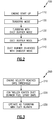
- Figure 2 is a flowchart 100 illustrating the modes of operation in which the turbine engine structure 10 can function.
- the engine 10 operates in an engine startup mode 110.
- the engine 10 continues operations during takeoff, landing, and other low speed operations in a turbofan mode 120.
- the turbofan mode 120 the engine is operating as a standard gas turbine engine.
- the turbofan mode 120 is unable to provide sufficient thrust to maintain the aircraft at speeds above a certain Mach level.
- low speed operations cannot safely exceed sonic speeds.
- the engine 10 enters a turbofan with duct burner mode 130.
- the turbofan with duct burner mode can be entered while the aircraft is on the ground just prior to take-off.
- the augmenter fuel spray bars 50 are ignited and operate the turbine engine structure 10 as a duct burning turbine engine, providing additional thrust and enabling higher Mach speeds.
- the engine 10 can safely operate at up to Mach 2.0-2.5.
- the operations in the turbofan with duct burner mode130 are described in greater detail below, with regards to Figure 3 .
- Figure 3 illustrates a flowchart 200 demonstrating transition of the engine to the mid speed operations mode 130, and operations within the turbofan with duct burner mode 130.
- the controller 40 begins ignition of the augmenter fuel spray bars 50 at block 220. Once the augmenter fuel spray bars 50 are ignited, the resultant combustion gasses are expelled through the bypass flowpath 16, increasing the thrust provided during the turbofan with duct burner mode 130. Once the augmenter fuel spray bars 50 are fully ignited, the turbine engine structure 10 is operated as an duct burning turbine engine at block 230.
- the engine core 20 continues to provide standard gas turbine engine operations, drawing air into the core flowpath 14 upstream of the augmenter fuel spray bars 50.
- the compressor section 22 compresses the air
- the combustor section 24 mixes the compressed air with a fuel, and ignites the mixture
- the resultant combustion gasses are expanded across the turbine section 26.
- the expansion of the resultant combustion gasses drives the turbine section 26 to rotate, which in turn drives a shaft.
- the gasses are exhausted from the turbine section 26, join the exhaust gasses from the afterburner and are expelled from the engine 10.
- the jet fuel from the augmenter fuel spray bars 50 is mixed with air passing through the flowpath 12 in a typical afterburner fashion. Due to the composition of the air and the materials of the engine 10, there is a condition that cannot realistically be exceeded. As a result of the limiting condition, the magnitude of thrust that can be provided in the turbofan with duct burner mode 130 limits the engine 10 to traveling at approximately Mach 2.0 - 2.5.
- the specific engine speed limit of a given engine 10 can be empirically or theoretically determined, and the engine controller 40 can utilize a predetermined speed threshold to determine when the transition from the turbofan with duct burner mode 130 to the duct burner enhanced with oxidizers mode 140 is necessary.
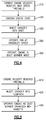
- the transition to, and operations in, the duct burner only mode 135 is illustrated in Figure 4 .
- the controller 40 cocoons the engine core 20 using the engine cocooning mechanisms 82,86 at a cocoon engine core block 320. Cocooning the engine core 320 partially or completely blocks a flow of air from said flowpath 12 into said core flowpath 14, thereby preventing air from entering the engine core 20, and preventing the engine core 20 from operating as a turbine engine.
- the jet fuel motor 60 continues to rotate the engine spool at block 340.
- the jet fuel motor 60 drives the spool such that the delta pressure across the fan is zero or greater and does not impede flow to the duct burner, such that the engine accessories (fuel pumps, oil pumps, generator, etc.) still operate and that brinelling of the engine bearings is avoided.
- this rotational speed of the fan required to achieve this state is referred to as a speed of invisibility.
- the engine 10 includes a duct burner enhanced with oxidizer mode.
- Figure 5 illustrates a flowchart demonstrating transition from a duct burning only mode to a duct burner enhanced with oxidizer mode. Initially, the engine 10 reaches a velocity threshold that is at or near the practical limit of the duct burner mode at block 410.
- the engine 10 begins injecting oxidizer into the flowpath at block 420, entering the duct burner with oxidizer enhancement mode 140.
- the oxidizer injector 70 begins injecting an oxidizing agent into the flowpath 12 at or near the augmenter fuel spray bars 50.
- the oxidizer is a combustible compound that replaces at least a portion of the air passing through the flowpath. By replacing the some of the air with the oxidizer, the engine 10 can provide the necessary thrust to operate at increased Mach numbers. In this mode, the engine 10 is operating as an oxidizer enhanced augmenter. Once the engine 10 has begun injecting oxidizer into the flowpath, the engine 10 operates as a duct burner enhanced with oxidizer at block 430.
- the oxidizer is one of liquid oxygen, nitrous oxide and hydrogen peroxide.
- the oxidizer is liquid oxygen.
- the oxidizer is a combination of liquid oxygen and nitrous oxide.
- a substantial portion of the air passing through the flowpath is replaced with the oxidizer.
- 75% - 80% of the air passing through the flowpath 12 can be replaced with the oxidizer.
- the oxidizer / air mixture is then ignited by the augmenter fuel spray bars 50, creating the heated combustion gasses.
Landscapes
- Engineering & Computer Science (AREA)
- Chemical & Material Sciences (AREA)
- Combustion & Propulsion (AREA)
- Mechanical Engineering (AREA)
- General Engineering & Computer Science (AREA)
- Structures Of Non-Positive Displacement Pumps (AREA)
- Control Of Turbines (AREA)
Abstract
Description
- The present disclosure relates generally to turbine engine structures, and particularly to a turbine engine structure including an oxidizer enhanced duct burner propulsion mode.
- Turbofan engines typically include an engine core having a compressor, a combustor, and a turbine section. The compressor, combustor and turbine section operate cooperatively to drive rotation of a shaft. The shaft is connected to a fan either directly, in a direct drive configuration, or via a gearing system in a geared turbofan configuration. The fan drives air along a bypass flowpath and through the engine core. Existing turbofan engines are unable to exceed certain Mach numbers, even with the inclusion of features designed to mitigate the effects of high speeds.
- In one exemplary embodiment, a turbine engine structure includes a turbine engine core including a core cocooning feature a fan fore of the turbine engine core, relative to fluid flow through the turbine engine structure, wherein the fan is drivably connected to the turbine engine core via a shaft, a nacelle circumferentially surrounding the turbine engine core, a bypass flowpath defined between the turbine engine core and the nacelle, and a plurality of augmenter fuel spray bars disposed in the bypass flowpath.
- In another exemplary embodiment of the above exemplary embodiment the turbine engine core is configured to be open in a first condition and cocooned in a second condition, and wherein the first condition is a Mach speed of the turbine engine structure below a first predetermined threshold, and the second condition is a Mach speed of the turbine engine structure above a second predetermined threshold.
- In another exemplary embodiment of any of the above exemplary embodiments the plurality of augmenter fuel spray bars are configured to operate as a duct burner in a third condition, wherein the third condition is a Mach speed of the turbine engine structure between the first predetermined threshold and the second predetermined threshold.
- An exemplary embodiment of any of the above exemplary embodiments further includes a jet fuel motor configured to drive a shaft, the shaft being further connected to the fan, such that the shaft is capable of driving the fan.
- In another exemplary embodiment of any of the above exemplary embodiments the jet fuel motor is configured to operate as a starter motor.
- In another exemplary embodiment of any of the above exemplary embodiments the jet fuel motor is configured to drive the fan at a unobstructed flow operating condition when the Mach speed of the turbine engine structure is above a predetermined threshold.
- An exemplary embodiment of any of the above exemplary embodiments further includes a controller controllably coupled to at least the engine core and the augmenter fuel spray bars and wherein the controller is configured to control the core cocooning feature.
- An exemplary embodiment of any of the above exemplary embodiments further includes an oxidizer injector configured to at least partially supplement air in the bypass flowpath with an oxidizer when the engine is operating in a second condition, the second condition is a Mach speed of the turbine engine structure above a second predetermined threshold.
- An exemplary embodiment of any of the above exemplary embodiments further includes a cooling system configured to cool at least one of non-core engine static structures and the fan using one of a jet fuel and an oxidizer.
- In another exemplary embodiment, a turbine engine structure includes an engine structure configured to operate as a turbofan engine in a first condition and configured to operate as a duct burner enhanced with oxidizer engine in a second condition.
- In another exemplary embodiment of any of the above exemplary embodiments the first condition is a Mach speed of the turbine engine structure below a first predetermined threshold, and the second condition is a Mach speed of the turbine engine structure above a second predetermined threshold.
- In another exemplary embodiment of any of the above exemplary embodiments the engine structure is further configured to operate as a duct burner engine in a third condition.
- In another exemplary embodiment of any of the above exemplary embodiments the third condition is a Mach speed of the turbine engine structure between a first predetermined threshold and a second predetermined threshold.
- An exemplary embodiment of any of the above exemplary embodiments further includes a jet fuel motor configured to drive an engine fan at a speed of invisibility during the second condition.
- An exemplary embodiment of any of the above exemplary embodiments further includes an oxidizer injector operable to at least partially supplement air in a bypass flowpath with an oxidizer while the engine structure is in the second condition.
- In another exemplary embodiment of any of the above exemplary embodiments the engine structure is configured to operate as a direct drive turbofan engine in the first condition.
- In another exemplary embodiment, a method for operating a turbine engine includes operating a turbine engine structure in a turbofan mode when the engine is in a first condition, cocooning the turbine engine structure when the turbine engine structure enters a second condition, and operating the turbine engine structure in a duct burner enhanced with oxidizer mode when the turbine engine structure is in the second condition.
- An exemplary embodiment of any of the above exemplary embodiments further includes operating the turbine engine structure in an a duct burner mode when the turbine engine structure is in a third condition.
- In another exemplary embodiment of any of the above exemplary embodiments cocooning the turbine engine structure incudes at least partially restricting air flow into an engine core such that the engine core is not operating as a gas turbine engine.
- In another exemplary embodiment of any of the above exemplary embodiments operating the turbine engine structure in the duct burner enhanced with oxidizer mode incudes at least partially supplementing air in a flowpath of the turbine engine structure with an oxidizer upstream of a plurality of jet fuel burners.
- These and other features of the present invention can be best understood from the following specification and drawings, the following of which is a brief description.
-
-
Figure 1 schematically illustrates an exemplary turbine engine structure. -
Figure 2 illustrates a flowchart detailing operations of the turbine engine structure ofFigure 1 . -
Figure 3 illustrates a flowchart demonstrating a transition of the engine to a turbofan duct burner mode. -
Figure 4 illustrates a flowchart demonstrating a transition of the engine to a duct burner only mode. -
Figure 5 illustrates a flowchart demonstrating transition from a duct burning only mode to a duct burner enhanced with oxidizer mode. -
Figure 1 schematically illustrates an exemplaryturbine engine structure 10. Theturbine engine structure 10 includes aflowpath 12 that splits into acore flowpath 14 and abypass flowpath 16. Thecore flowpath 14 passes through anengine core 20 including acompressor section 22, acombustor section 24 and a turbine section 26. Fore of theengine core 20 is afan 30 that spans theflowpath 12. Fore of thefan 30 is an inlet that provides minimal pressure loss and a desired mass flow of the incoming air. Thefan 30 is connected to theengine core 20 in the illustrated embodiment via agear 32. The connection between thefan 30 and theengine core 20 allows theengine core 20 to drive rotation of thefan 30 in theflowpath 12. In alternative examples, thefan 30 is directly connected to theengine core 20 via a shaft in a direct drive arrangement instead of the illustrated geared connection. Theengine core 20 utilizes standard turbofan operations to generate thrust in combination with thefan 30 during low speed operations and take off/landing. - Further, included in the
turbine engine structure 10 is a variable area convergent/divergent nozzle at an exit end of theflowpath 12. The area ratios and absolute areas of the convergent/divergent nozzle are scheduled to optimize engine operations throughout the engine modes. - A
controller 40 controls operations of theengine core 20, as well as other operations within theturbine engine structure 10. In some embodiments, thecontroller 40 is positioned within theengine core 20 as illustrated inFigure 1 . By way of example, the illustratedengine core 20 includes a cooling system, providing a suitable location for housing thecontroller 40. In alternative embodiments, thecontroller 40 can be positioned elsewhere on theturbine engine structure 10, or exterior to theturbine engine structure 10, depending on the structure and needs of a specific turbine engine structure. - Further included in the
turbine engine structure 10 arecocooning mechanisms cocooning mechanisms engine core 20 from theflowpath 12. Cocooning theengine core 20 includes isolating theengine core 20 from theflowpath 12 and preventing air in theflowpath 12 from entering theengine core 20. By preventing air from entering theengine core 20, turbine engine operations are halted and thrust is provided by the burning of jet fuel at the augmenterfuel spray bars 50. While cocooned, theengine core 20 is rotated by thejet fuel motor 60. Further, while cocooned, theengine core 20 is cooled by the cooling system in order to protect the engine core from heat associated with the high Mach modes of operation. During the high Mach modes of operation the remaining engine static structure is cooled using either jet fuel or oxidizer. In some examples, thefan 30 is further cooled by passing jet fuel through the fan and expelling the jet fuel from the fan blades. In these examples, a duct burner zone is created immediately aft of the fan. In the illustrated example, the cocooning mechanism takes the form of a physical barrier at an inlet of thecore flowpath 14 and a physical barrier at an outlet of thecore flowpath 14. In order to operate the engine in a turbine mode again, thecocooning mehcanisms 80, 82 allow air back into the engine core, and the turbine engine operations are restarted via thejet fuel motor 60. - The
engine core 20 is supported radially, relative to anacelle 90 housing theengine core 20, bymultiple struts 52 arranged circumferentially around theengine core 20. Disposed across at least some of thestruts 52 are multiple augmenterfuel spray bars 50. The augmenter fuel spray bars 50 are arranged circumferentially around theengine core 20, as with thestruts 52 and operate in conjunction with each other as a duct burner. In alternative embodiments, the augmenter fuel spray bars 50 can be positioned in theflowpath 12 using an alternative support structure and achieve the same effect. - Each of the augmenter fuel spray bars 50 is connected to a jet fuel repository, such as a jet fuel tank, via one or more jet
fuel supply tubes 57. The jetfuel supply tubes 57 are connected to the jet fuel repository at aninlet 59, and are capable of supplying jet fuel to the augmenter fuel spray bars 50 and to thejet fuel motor 60. Jet fuel is provided from the jet fuel repository, and ignited at the augmenter fuel spray bars 50 to provide additional thrust, when the additional thrust is needed. At mid speed operations, the augmenter fuel spray bars 50 operate as an afterburner (alternately referred to as an augmenter or a re-heater). At high speed operations, the augmenter fuel spray bars 50 are supplemented with oxidizer injected at a near location or upstream in the jet engine. In the example ofFigure 1 , the operations of the augmenter fuel spray bars 50 are controlled by thecontroller 40. In alternative examples, a dedicated jet fuel burner controller can be used in place of thegeneral engine controller 40. - A
Jet fuel motor 60 is connected to thefan 30. Thejet fuel motor 60 is a motor that operates off jet fuel and oxidizer. The jet fuel motor utilizes combustion of jet fuel within an environment at least partially comprising an oxidizer agent to generate rotational movement of a shaft. The shaft of thejet fuel motor 60 is physically connected to thefan 30 through a gearbox. Thejet fuel motor 60 operates as a starter motor for theturbine engine structure 10. In another mode, at high speed when theengine core 20 is cocooned, thejet fuel motor 60 drives the fan to rotate it fast enough such that the delta pressure across the fan is zero or greater. In the illustrated example, thejet fuel motor 60 is connected to thefan 30 via agearing system 62. Unlike a conventional jet fuel based starter motor, thejet fuel motor 60 combusts jet fuel with oxidizer to generate rotational motion. In alternative systems, thejet fuel motor 60 can be connected to thefan 30 directly in a direct drive fashion. - In some examples, the
jet fuel motor 60 provides two primary functions during operation of theturbine engine structure 10. Initially, thejet fuel motor 60 operates as a starter motor providing initial rotational motion through the fan to theengine core 20, allowing theturbine engine structure 10 to begin operations for takeoff. Once operating, when theturbine engine structure 10 enters high speed operations where theengine 10 functions in an augmenter mode, thejet fuel motor 60 drives thefan 30 to rotate fast enough that thefan 30 does not impart drag on the air entering theflowpath 12. Driving the fan at a condition where the pressure rise across it is approximately zero effectively renders the fan invisible for the purposes of fluid flow through theturbine engine structure 10, and both keeps the fan from interfering with high speed performance and maintains the rotation of the gearbox to drive the engine accessories (fuel pumps, oil pumps, generators, etc.) when the core is cocooned. The operating condition at which this is accomplished is referred to as an unobstructed flow operating condition for the fan. - Further included at, or near, the augmenter fuel spray bars 50 are one or
more oxidizer injectors 70. The oxidizer injectors 70 inject an oxidizer, such as Liquid Oxygen, Nitrous Oxide, a combination of the foregoing, or Hydrogen Peroxide, into theflowpath 12, thereby supplementing the air passing through theflowpath 12 with the oxidizer. The oxidizer allows more fuel to be combusted and reduces the ram drag proportional to the amount of fuel combusted. - With continued reference to the
turbine engine 10 described above and illustrated inFigure 1 ,Figure 2 is aflowchart 100 illustrating the modes of operation in which theturbine engine structure 10 can function. Initially, theengine 10 operates in anengine startup mode 110. Once theengine core 20 has been started, theengine 10 continues operations during takeoff, landing, and other low speed operations in aturbofan mode 120. In theturbofan mode 120, the engine is operating as a standard gas turbine engine. Theturbofan mode 120 is unable to provide sufficient thrust to maintain the aircraft at speeds above a certain Mach level. By way of example, in some engines, low speed operations cannot safely exceed sonic speeds. - When the aircraft needs to exceed the safe low speed operations, the
engine 10 enters a turbofan withduct burner mode 130. In other embodiments, the turbofan with duct burner mode can be entered while the aircraft is on the ground just prior to take-off. In the turbofan withduct burner mode 130, the augmenter fuel spray bars 50 are ignited and operate theturbine engine structure 10 as a duct burning turbine engine, providing additional thrust and enabling higher Mach speeds. By way of example, in one embodiment during mid speed operations, theengine 10 can safely operate at up to Mach 2.0-2.5. The operations in the turbofan with duct burner mode130 are described in greater detail below, with regards toFigure 3 . - Due to turbine engine limitations, including drag, cooling, and the like, practical implementations of duct burning turbine engines are incapable of exceeding certain Mach numbers. When a velocity in excess of the practical limitations on a turbine engine is desired, the
turbine engine 10 transitions to a higherspeed operations mode 135, where the engine operates as a duct burner only and the turbine engine operations are temporarily deactivated. Duct burner only mode operations are described in greater detail below with regards toFigure 4 . - Due to duct burner only engine limitations, including cooling, exhaust gas velocity and the like, practical limitations of duct burner only engines prevent the duct burner only engines from exceeding certain Mach numbers. When a velocity in excess of the practical limitations is desired, the engine transitions to a higher
speed operation mode 140 where the combustion duct burner in the duct burner is enhanced with oxidizer. Duct burner enhanced with oxidizer mode operations are described in greater details with regards toFigure 5 . - With continued regards to
Figures 1 and2, Figure 3 illustrates aflowchart 200 demonstrating transition of the engine to the midspeed operations mode 130, and operations within the turbofan withduct burner mode 130. Initially, when the engine speed reaches the safe threshold of standard turbine engine operations atblock 210, thecontroller 40 begins ignition of the augmenter fuel spray bars 50 atblock 220. Once the augmenter fuel spray bars 50 are ignited, the resultant combustion gasses are expelled through thebypass flowpath 16, increasing the thrust provided during the turbofan withduct burner mode 130. Once the augmenter fuel spray bars 50 are fully ignited, theturbine engine structure 10 is operated as an duct burning turbine engine atblock 230. - Simultaneous with receiving the thrust boost from the augmenter fuel spray bars 50 operating as afterburners, the
engine core 20 continues to provide standard gas turbine engine operations, drawing air into thecore flowpath 14 upstream of the augmenter fuel spray bars 50. In thecore flowpath 14, thecompressor section 22 compresses the air, thecombustor section 24 mixes the compressed air with a fuel, and ignites the mixture, and the resultant combustion gasses are expanded across the turbine section 26. The expansion of the resultant combustion gasses drives the turbine section 26 to rotate, which in turn drives a shaft. The gasses are exhausted from the turbine section 26, join the exhaust gasses from the afterburner and are expelled from theengine 10. - While operating as an afterburner, the jet fuel from the augmenter fuel spray bars 50 is mixed with air passing through the
flowpath 12 in a typical afterburner fashion. Due to the composition of the air and the materials of theengine 10, there is a condition that cannot realistically be exceeded. As a result of the limiting condition, the magnitude of thrust that can be provided in the turbofan withduct burner mode 130 limits theengine 10 to traveling at approximately Mach 2.0 - 2.5. The specific engine speed limit of a givenengine 10 can be empirically or theoretically determined, and theengine controller 40 can utilize a predetermined speed threshold to determine when the transition from the turbofan withduct burner mode 130 to the duct burner enhanced withoxidizers mode 140 is necessary. - With continued reference to
Figures 1-3 , the transition to, and operations in, the duct burner onlymode 135 is illustrated inFigure 4 . When theengine 10 reaches the velocity threshold, theengine 10 enters the duct burner onlymode 135 atblock 310. Initially, thecontroller 40 cocoons theengine core 20 using theengine cocooning mechanisms engine core block 320. Cocooning theengine core 320 partially or completely blocks a flow of air from said flowpath 12 into saidcore flowpath 14, thereby preventing air from entering theengine core 20, and preventing theengine core 20 from operating as a turbine engine. While the illustrated embodiment utilizesmechanical mechanisms engine core 20, one of skill in the art, having the benefit of this disclosure, will understand that any alternate cocooning system capable of at least partially blocking airflow into thecore flowpath 14 can function in a similar capacity. - Once the
engine core 20 is cocooned, thejet fuel motor 60 continues to rotate the engine spool atblock 340. Thejet fuel motor 60 drives the spool such that the delta pressure across the fan is zero or greater and does not impede flow to the duct burner, such that the engine accessories (fuel pumps, oil pumps, generator, etc.) still operate and that brinelling of the engine bearings is avoided. As described above, this rotational speed of the fan required to achieve this state is referred to as a speed of invisibility. - In some examples, Mach speeds higher than can practicably be achieved by a duct burner only mode are required. In such an example, the
engine 10 includes a duct burner enhanced with oxidizer mode.Figure 5 illustrates a flowchart demonstrating transition from a duct burning only mode to a duct burner enhanced with oxidizer mode. Initially, theengine 10 reaches a velocity threshold that is at or near the practical limit of the duct burner mode atblock 410. - When the threshold is reached, the
engine 10 begins injecting oxidizer into the flowpath atblock 420, entering the duct burner withoxidizer enhancement mode 140. Once the engine enters the duct burner with oxidizer enhancement mode 150, theoxidizer injector 70 begins injecting an oxidizing agent into theflowpath 12 at or near the augmenter fuel spray bars 50. The oxidizer is a combustible compound that replaces at least a portion of the air passing through the flowpath. By replacing the some of the air with the oxidizer, theengine 10 can provide the necessary thrust to operate at increased Mach numbers. In this mode, theengine 10 is operating as an oxidizer enhanced augmenter. Once theengine 10 has begun injecting oxidizer into the flowpath, theengine 10 operates as a duct burner enhanced with oxidizer atblock 430. - In some examples, the oxidizer is one of liquid oxygen, nitrous oxide and hydrogen peroxide. In the illustrated example of
Figure 1 , the oxidizer is liquid oxygen. In another example, the oxidizer is a combination of liquid oxygen and nitrous oxide. In practical operations a substantial portion of the air passing through the flowpath is replaced with the oxidizer. By way of example 75% - 80% of the air passing through theflowpath 12 can be replaced with the oxidizer. The oxidizer / air mixture is then ignited by the augmenter fuel spray bars 50, creating the heated combustion gasses. - It is further understood that any of the above described concepts can be used alone or in combination with any or all of the other above described concepts. Although an embodiment of this invention has been disclosed, a worker of ordinary skill in this art would recognize that certain modifications would come within the scope of this invention. For that reason, the following claims should be studied to determine the true scope and content of this invention.
Claims (15)
- A turbine engine structure (10) comprising:an turbine engine core (20) including a core cocooning feature (82,86);a fan (30) fore of said turbine engine core (20), relative to fluid flow through said turbine engine structure (10), wherein the fan (30) is drivably connected to said turbine engine core (20) via a shaft;a nacelle (90) circumferentially surrounding said turbine engine core (20);a bypass flowpath (16) defined between said turbine engine core (20) and said nacelle (90); anda plurality of augmenter fuel spray bars (50) disposed in said bypass flowpath (16).
- The turbine engine structure of claim 1, wherein the turbine engine core (20) is configured to be open in a first condition and cocooned in a second condition, and wherein the first condition is a Mach speed of the turbine engine structure (20) below a first predetermined threshold, and the second condition is a Mach speed of the turbine engine structure above a second predetermined threshold.
- The turbine engine structure of claim 2, wherein said plurality of augmenter fuel spray bars (50) are configured to operate as a duct burner in a third condition, wherein the third condition is a Mach speed of the turbine engine structure between the first predetermined threshold and the second predetermined threshold.
- The turbine engine structure of any preceding claim, further comprising a jet fuel motor (60) configured to drive a shaft, the shaft being further connected to said fan (30), such that said shaft is capable of driving said fan (30).
- The turbine engine structure of claim 4, wherein the jet fuel motor (60) is configured to operate as a starter motor.
- The turbine engine structure of claim 4 or 5, wherein the jet fuel motor (60) is configured to drive said fan (30) at a unobstructed flow operating condition when the Mach speed of the turbine engine structure (10) is above a predetermined threshold.
- The turbine engine structure of any preceding claim, further comprising a controller (40) controllably coupled to at least said engine core (20) and said augmenter fuel spray bars (50) and wherein the controller (40) is configured to control the core cocooning feature (82,86).
- The turbine engine structure of any preceding claim, further comprising an oxidizer injector (70) configured to at least partially supplement air in said bypass flowpath (16) with an oxidizer when said engine is operating in a second condition, the second condition is a Mach speed of the turbine engine structure above a second predetermined threshold.
- The turbine engine structure of any preceding claim, further comprising a cooling system configured to cool at least one of non-core engine static structures and said fan (30) using one of a jet fuel and an oxidizer.
- A method for operating a turbine engine (10) comprising:operating a turbine engine structure (10) in a turbofan mode (120) when the engine is in a first condition;cocooning the turbine engine structure (10) when the turbine engine structure (10) enters a second condition; andoperating the turbine engine structure (10) in a duct burner enhanced with oxidizer mode (140) when the turbine engine structure (10) is in said second condition.
- The method of claim 10, further comprising operating the turbine engine structure (10) in an a duct burner mode (135) when the turbine engine structure (10) is in a third condition.
- The method of claim 10 or 11, wherein cocooning the turbine engine structure (10) comprises at least partially restricting air flow into an engine core (20) such that said engine core (20) is not operating as a gas turbine engine.
- The method of any of claims 10 to 12, wherein operating the turbine engine structure (10) in the duct burner enhanced with oxidizer mode (140) comprises at least partially supplementing air in a flowpath of said turbine engine structure (10) with an oxidizer upstream of a plurality of jet fuel burners (50).
- A turbine engine structure (10) comprising:an engine structure (10) configured to operate as a turbofan engine (120) in a first condition and configured to operate as a duct burner enhanced with oxidizer engine (140) in a second condition.
- The turbine engine structure of claim 14, wherein the engine structure (10) is further configured to operate as a duct burner engine in a third condition, wherein the third condition is a Mach speed of the turbine engine structure (10) between a first predetermined threshold and a second predetermined threshold.
Applications Claiming Priority (1)
| Application Number | Priority Date | Filing Date | Title |
|---|---|---|---|
| US14/619,382 US11041463B1 (en) | 2015-02-11 | 2015-02-11 | Turbine engine structure with oxidizer enhanced mode |
Publications (2)
| Publication Number | Publication Date |
|---|---|
| EP3056722A1 true EP3056722A1 (en) | 2016-08-17 |
| EP3056722B1 EP3056722B1 (en) | 2019-11-20 |
Family
ID=55587009
Family Applications (1)
| Application Number | Title | Priority Date | Filing Date |
|---|---|---|---|
| EP16155305.2A Active EP3056722B1 (en) | 2015-02-11 | 2016-02-11 | Turbine engine structure with oxidizer enhanced mode |
Country Status (2)
| Country | Link |
|---|---|
| US (1) | US11041463B1 (en) |
| EP (1) | EP3056722B1 (en) |
Families Citing this family (2)
| Publication number | Priority date | Publication date | Assignee | Title |
|---|---|---|---|---|
| GB2582529B (en) * | 2020-06-25 | 2021-03-24 | Qureshi Sarah | A supersonic turbofan engine |
| US12065965B1 (en) | 2023-08-15 | 2024-08-20 | Rolls-Royce North American Technologies Inc. | Rotating detonation augmentors with adjustable throats for gas turbine engines |
Citations (4)
| Publication number | Priority date | Publication date | Assignee | Title |
|---|---|---|---|---|
| US3812672A (en) * | 1972-02-10 | 1974-05-28 | Cci Aerospace Corp | Supercharged ejector ramjet aircraft engine |
| GB2205360A (en) * | 1987-05-27 | 1988-12-07 | Mtu Muenchen Gmbh | Composite fanjet/ramjet propulsion device |
| US5012638A (en) * | 1988-09-01 | 1991-05-07 | Mtu Motoren- Und Turbinen-Union Munchen Gmbh | Fuel feed method and apparatus for a turboramjet engine |
| FR2687433A1 (en) * | 1992-02-14 | 1993-08-20 | Onera (Off Nat Aerospatiale) | Propulsion unit with reversed components, with modulated supply |
Family Cites Families (27)
| Publication number | Priority date | Publication date | Assignee | Title |
|---|---|---|---|---|
| US2696079A (en) * | 1950-04-17 | 1954-12-07 | Peter G Kappus | Dual jet aircraft power plant |
| US3002340A (en) | 1957-04-05 | 1961-10-03 | United Aircraft Corp | Rocket gas generator for turbofan engine |
| US2955414A (en) * | 1957-09-03 | 1960-10-11 | United Aircraft Corp | Combined power plant |
| US2952973A (en) * | 1958-06-02 | 1960-09-20 | Gen Motors Corp | Turbofan-ramjet engine |
| US3677012A (en) * | 1962-05-31 | 1972-07-18 | Gen Electric | Composite cycle turbomachinery |
| FR1496091A (en) * | 1966-04-20 | 1967-09-29 | Snecma | Ejection nozzle for thrusters with several motor flows, in particular with two motor flows |
| US3938328A (en) * | 1971-11-08 | 1976-02-17 | The Boeing Company | Multicycle engine |
| US4137708A (en) * | 1973-07-02 | 1979-02-06 | General Motors Corporation | Jet propulsion |
| US4543785A (en) * | 1982-07-07 | 1985-10-01 | Hugh Patrick | Turbo-ram-jet engine |
| US5003767A (en) * | 1988-03-25 | 1991-04-02 | Sundstrand Corporation | Gas turbine starter system with power augmentation |
| US5052176A (en) | 1988-09-28 | 1991-10-01 | Societe Nationale D'etude Et De Construction De Moteurs D'aviation | Combination turbojet-ramjet-rocket propulsion system |
| US5105615A (en) * | 1989-02-03 | 1992-04-21 | Mtu Motoren- Und Turbinen-Union Munchen Gmbh | Turbojet engine with at least one axially movable arranged sliding valve |
| US5054284A (en) * | 1989-03-17 | 1991-10-08 | Sundstrand Corporation | Combustion heated air turbine starter system |
| DE3911715A1 (en) * | 1989-04-10 | 1990-10-11 | Mtu Muenchen Gmbh | SHUT-OFF DEVICE FOR BLOWED, IN PARTICULAR BLOWED, RADIANT JET ENGINES |
| DE3934268A1 (en) * | 1989-10-13 | 1991-04-25 | Mtu Muenchen Gmbh | TURBINE JET ENGINE |
| US5694768A (en) * | 1990-02-23 | 1997-12-09 | General Electric Company | Variable cycle turbofan-ramjet engine |
| US5160080A (en) | 1990-10-01 | 1992-11-03 | General Electric Company | Gas turbine engine and method of operation for providing increased output shaft horsepower |
| DE4131913A1 (en) | 1991-09-25 | 1993-04-08 | Mtu Muenchen Gmbh | COOLING DEVICE FOR HYPERSONIC AIR JET ENGINES |
| GB2354041B (en) * | 2000-07-04 | 2003-11-19 | Adrian Alexander Hubbard | Variable mode jet engine-compact |
| CA2329555A1 (en) * | 2000-12-22 | 2002-06-22 | Jose Albero | Main propulsion engine system integrated with secondary power unit |
| US6644015B2 (en) | 2001-10-29 | 2003-11-11 | Hmx, Inc. | Turbojet with precompressor injected oxidizer |
| US7216474B2 (en) * | 2004-02-19 | 2007-05-15 | Aerojet-General Corporation | Integrated air inlet system for multi-propulsion aircraft engines |
| US7305816B2 (en) | 2004-08-13 | 2007-12-11 | United Technologies Corporation | Rocket augmentation for combined cycle turboaccelerator jet engine |
| US8281567B2 (en) | 2005-07-27 | 2012-10-09 | Aryeh Yaakov Kohn | Deployable rocket engine in a combination jet and rocket engine |
| US7721524B2 (en) | 2006-02-15 | 2010-05-25 | United Technologies Corporation | Integrated airbreathing and non-airbreathing engine system |
| FR2967725B1 (en) * | 2010-11-23 | 2012-12-14 | Snecma | COMBINED TURBOREACTOR AND STATOREACTOR COMBINATION PROPELLER |
| US8695540B2 (en) | 2012-06-18 | 2014-04-15 | Aerojet Rocketdyne Of De, Inc. | Fuel-cracking diesel engine system |
-
2015
- 2015-02-11 US US14/619,382 patent/US11041463B1/en active Active
-
2016
- 2016-02-11 EP EP16155305.2A patent/EP3056722B1/en active Active
Patent Citations (4)
| Publication number | Priority date | Publication date | Assignee | Title |
|---|---|---|---|---|
| US3812672A (en) * | 1972-02-10 | 1974-05-28 | Cci Aerospace Corp | Supercharged ejector ramjet aircraft engine |
| GB2205360A (en) * | 1987-05-27 | 1988-12-07 | Mtu Muenchen Gmbh | Composite fanjet/ramjet propulsion device |
| US5012638A (en) * | 1988-09-01 | 1991-05-07 | Mtu Motoren- Und Turbinen-Union Munchen Gmbh | Fuel feed method and apparatus for a turboramjet engine |
| FR2687433A1 (en) * | 1992-02-14 | 1993-08-20 | Onera (Off Nat Aerospatiale) | Propulsion unit with reversed components, with modulated supply |
Also Published As
| Publication number | Publication date |
|---|---|
| EP3056722B1 (en) | 2019-11-20 |
| US20210164416A1 (en) | 2021-06-03 |
| US11041463B1 (en) | 2021-06-22 |
Similar Documents
| Publication | Publication Date | Title |
|---|---|---|
| US11939925B2 (en) | Descent operation for an aircraft parallel hybrid gas turbine engine propulsion system | |
| CN109028149B (en) | Variable geometry rotary detonation combustor and method of operating same | |
| CN109028142B (en) | Propulsion system and method of operating the same | |
| US6442930B1 (en) | Combined cycle pulse detonation turbine engine | |
| US10641169B2 (en) | Hybrid combustor assembly and method of operation | |
| US11131461B2 (en) | Effervescent atomizing structure and method of operation for rotating detonation propulsion system | |
| EP4227507B1 (en) | Engine system and method of operating the same | |
| EP4227506B1 (en) | Engine system and method of operating the same | |
| EP3056722B1 (en) | Turbine engine structure with oxidizer enhanced mode | |
| CN103629011B (en) | Motor | |
| EP3032071B1 (en) | Fuel schedule for robust gas turbine engine transition between steady states | |
| EP4227508B1 (en) | Engine system and method of operating the same | |
| US12169068B2 (en) | Combustor for a turbine engine | |
| US12259134B2 (en) | Hydrogen liquid oxygen combined cycle engine | |
| Pascoe | Start systems for aero gas turbines | |
| US20230008152A1 (en) | Metal-based fuel and fuel delivery systems | |
| RU174498U1 (en) | POWER INSTALLATION OF A HYPERSONIC AIRCRAFT |
Legal Events
| Date | Code | Title | Description |
|---|---|---|---|
| PUAI | Public reference made under article 153(3) epc to a published international application that has entered the european phase |
Free format text: ORIGINAL CODE: 0009012 |
|
| AK | Designated contracting states |
Kind code of ref document: A1 Designated state(s): AL AT BE BG CH CY CZ DE DK EE ES FI FR GB GR HR HU IE IS IT LI LT LU LV MC MK MT NL NO PL PT RO RS SE SI SK SM TR |
|
| AX | Request for extension of the european patent |
Extension state: BA ME |
|
| RAP1 | Party data changed (applicant data changed or rights of an application transferred) |
Owner name: UNITED TECHNOLOGIES CORPORATION |
|
| STAA | Information on the status of an ep patent application or granted ep patent |
Free format text: STATUS: REQUEST FOR EXAMINATION WAS MADE |
|
| 17P | Request for examination filed |
Effective date: 20170217 |
|
| RBV | Designated contracting states (corrected) |
Designated state(s): AL AT BE BG CH CY CZ DE DK EE ES FI FR GB GR HR HU IE IS IT LI LT LU LV MC MK MT NL NO PL PT RO RS SE SI SK SM TR |
|
| GRAP | Despatch of communication of intention to grant a patent |
Free format text: ORIGINAL CODE: EPIDOSNIGR1 |
|
| STAA | Information on the status of an ep patent application or granted ep patent |
Free format text: STATUS: GRANT OF PATENT IS INTENDED |
|
| INTG | Intention to grant announced |
Effective date: 20190529 |
|
| GRAS | Grant fee paid |
Free format text: ORIGINAL CODE: EPIDOSNIGR3 |
|
| GRAA | (expected) grant |
Free format text: ORIGINAL CODE: 0009210 |
|
| STAA | Information on the status of an ep patent application or granted ep patent |
Free format text: STATUS: THE PATENT HAS BEEN GRANTED |
|
| AK | Designated contracting states |
Kind code of ref document: B1 Designated state(s): AL AT BE BG CH CY CZ DE DK EE ES FI FR GB GR HR HU IE IS IT LI LT LU LV MC MK MT NL NO PL PT RO RS SE SI SK SM TR |
|
| REG | Reference to a national code |
Ref country code: GB Ref legal event code: FG4D |
|
| REG | Reference to a national code |
Ref country code: CH Ref legal event code: EP |
|
| REG | Reference to a national code |
Ref country code: IE Ref legal event code: FG4D |
|
| REG | Reference to a national code |
Ref country code: DE Ref legal event code: R096 Ref document number: 602016024510 Country of ref document: DE |
|
| REG | Reference to a national code |
Ref country code: AT Ref legal event code: REF Ref document number: 1204475 Country of ref document: AT Kind code of ref document: T Effective date: 20191215 |
|
| REG | Reference to a national code |
Ref country code: NL Ref legal event code: MP Effective date: 20191120 |
|
| REG | Reference to a national code |
Ref country code: LT Ref legal event code: MG4D |
|
| PG25 | Lapsed in a contracting state [announced via postgrant information from national office to epo] |
Ref country code: NL Free format text: LAPSE BECAUSE OF FAILURE TO SUBMIT A TRANSLATION OF THE DESCRIPTION OR TO PAY THE FEE WITHIN THE PRESCRIBED TIME-LIMIT Effective date: 20191120 Ref country code: SE Free format text: LAPSE BECAUSE OF FAILURE TO SUBMIT A TRANSLATION OF THE DESCRIPTION OR TO PAY THE FEE WITHIN THE PRESCRIBED TIME-LIMIT Effective date: 20191120 Ref country code: LV Free format text: LAPSE BECAUSE OF FAILURE TO SUBMIT A TRANSLATION OF THE DESCRIPTION OR TO PAY THE FEE WITHIN THE PRESCRIBED TIME-LIMIT Effective date: 20191120 Ref country code: BG Free format text: LAPSE BECAUSE OF FAILURE TO SUBMIT A TRANSLATION OF THE DESCRIPTION OR TO PAY THE FEE WITHIN THE PRESCRIBED TIME-LIMIT Effective date: 20200220 Ref country code: FI Free format text: LAPSE BECAUSE OF FAILURE TO SUBMIT A TRANSLATION OF THE DESCRIPTION OR TO PAY THE FEE WITHIN THE PRESCRIBED TIME-LIMIT Effective date: 20191120 Ref country code: GR Free format text: LAPSE BECAUSE OF FAILURE TO SUBMIT A TRANSLATION OF THE DESCRIPTION OR TO PAY THE FEE WITHIN THE PRESCRIBED TIME-LIMIT Effective date: 20200221 Ref country code: NO Free format text: LAPSE BECAUSE OF FAILURE TO SUBMIT A TRANSLATION OF THE DESCRIPTION OR TO PAY THE FEE WITHIN THE PRESCRIBED TIME-LIMIT Effective date: 20200220 Ref country code: LT Free format text: LAPSE BECAUSE OF FAILURE TO SUBMIT A TRANSLATION OF THE DESCRIPTION OR TO PAY THE FEE WITHIN THE PRESCRIBED TIME-LIMIT Effective date: 20191120 |
|
| PG25 | Lapsed in a contracting state [announced via postgrant information from national office to epo] |
Ref country code: RS Free format text: LAPSE BECAUSE OF FAILURE TO SUBMIT A TRANSLATION OF THE DESCRIPTION OR TO PAY THE FEE WITHIN THE PRESCRIBED TIME-LIMIT Effective date: 20191120 Ref country code: IS Free format text: LAPSE BECAUSE OF FAILURE TO SUBMIT A TRANSLATION OF THE DESCRIPTION OR TO PAY THE FEE WITHIN THE PRESCRIBED TIME-LIMIT Effective date: 20200320 Ref country code: HR Free format text: LAPSE BECAUSE OF FAILURE TO SUBMIT A TRANSLATION OF THE DESCRIPTION OR TO PAY THE FEE WITHIN THE PRESCRIBED TIME-LIMIT Effective date: 20191120 |
|
| PG25 | Lapsed in a contracting state [announced via postgrant information from national office to epo] |
Ref country code: AL Free format text: LAPSE BECAUSE OF FAILURE TO SUBMIT A TRANSLATION OF THE DESCRIPTION OR TO PAY THE FEE WITHIN THE PRESCRIBED TIME-LIMIT Effective date: 20191120 |
|
| PG25 | Lapsed in a contracting state [announced via postgrant information from national office to epo] |
Ref country code: CZ Free format text: LAPSE BECAUSE OF FAILURE TO SUBMIT A TRANSLATION OF THE DESCRIPTION OR TO PAY THE FEE WITHIN THE PRESCRIBED TIME-LIMIT Effective date: 20191120 Ref country code: ES Free format text: LAPSE BECAUSE OF FAILURE TO SUBMIT A TRANSLATION OF THE DESCRIPTION OR TO PAY THE FEE WITHIN THE PRESCRIBED TIME-LIMIT Effective date: 20191120 Ref country code: RO Free format text: LAPSE BECAUSE OF FAILURE TO SUBMIT A TRANSLATION OF THE DESCRIPTION OR TO PAY THE FEE WITHIN THE PRESCRIBED TIME-LIMIT Effective date: 20191120 Ref country code: DK Free format text: LAPSE BECAUSE OF FAILURE TO SUBMIT A TRANSLATION OF THE DESCRIPTION OR TO PAY THE FEE WITHIN THE PRESCRIBED TIME-LIMIT Effective date: 20191120 Ref country code: PT Free format text: LAPSE BECAUSE OF FAILURE TO SUBMIT A TRANSLATION OF THE DESCRIPTION OR TO PAY THE FEE WITHIN THE PRESCRIBED TIME-LIMIT Effective date: 20200412 Ref country code: EE Free format text: LAPSE BECAUSE OF FAILURE TO SUBMIT A TRANSLATION OF THE DESCRIPTION OR TO PAY THE FEE WITHIN THE PRESCRIBED TIME-LIMIT Effective date: 20191120 |
|
| REG | Reference to a national code |
Ref country code: AT Ref legal event code: MK05 Ref document number: 1204475 Country of ref document: AT Kind code of ref document: T Effective date: 20191120 |
|
| REG | Reference to a national code |
Ref country code: DE Ref legal event code: R097 Ref document number: 602016024510 Country of ref document: DE |
|
| PG25 | Lapsed in a contracting state [announced via postgrant information from national office to epo] |
Ref country code: SK Free format text: LAPSE BECAUSE OF FAILURE TO SUBMIT A TRANSLATION OF THE DESCRIPTION OR TO PAY THE FEE WITHIN THE PRESCRIBED TIME-LIMIT Effective date: 20191120 Ref country code: SM Free format text: LAPSE BECAUSE OF FAILURE TO SUBMIT A TRANSLATION OF THE DESCRIPTION OR TO PAY THE FEE WITHIN THE PRESCRIBED TIME-LIMIT Effective date: 20191120 |
|
| PLBE | No opposition filed within time limit |
Free format text: ORIGINAL CODE: 0009261 |
|
| STAA | Information on the status of an ep patent application or granted ep patent |
Free format text: STATUS: NO OPPOSITION FILED WITHIN TIME LIMIT |
|
| REG | Reference to a national code |
Ref country code: CH Ref legal event code: PL |
|
| 26N | No opposition filed |
Effective date: 20200821 |
|
| REG | Reference to a national code |
Ref country code: BE Ref legal event code: MM Effective date: 20200229 |
|
| PG25 | Lapsed in a contracting state [announced via postgrant information from national office to epo] |
Ref country code: LU Free format text: LAPSE BECAUSE OF NON-PAYMENT OF DUE FEES Effective date: 20200211 Ref country code: MC Free format text: LAPSE BECAUSE OF FAILURE TO SUBMIT A TRANSLATION OF THE DESCRIPTION OR TO PAY THE FEE WITHIN THE PRESCRIBED TIME-LIMIT Effective date: 20191120 |
|
| PG25 | Lapsed in a contracting state [announced via postgrant information from national office to epo] |
Ref country code: SI Free format text: LAPSE BECAUSE OF FAILURE TO SUBMIT A TRANSLATION OF THE DESCRIPTION OR TO PAY THE FEE WITHIN THE PRESCRIBED TIME-LIMIT Effective date: 20191120 Ref country code: AT Free format text: LAPSE BECAUSE OF FAILURE TO SUBMIT A TRANSLATION OF THE DESCRIPTION OR TO PAY THE FEE WITHIN THE PRESCRIBED TIME-LIMIT Effective date: 20191120 Ref country code: LI Free format text: LAPSE BECAUSE OF NON-PAYMENT OF DUE FEES Effective date: 20200229 Ref country code: CH Free format text: LAPSE BECAUSE OF NON-PAYMENT OF DUE FEES Effective date: 20200229 Ref country code: PL Free format text: LAPSE BECAUSE OF FAILURE TO SUBMIT A TRANSLATION OF THE DESCRIPTION OR TO PAY THE FEE WITHIN THE PRESCRIBED TIME-LIMIT Effective date: 20191120 |
|
| PG25 | Lapsed in a contracting state [announced via postgrant information from national office to epo] |
Ref country code: IT Free format text: LAPSE BECAUSE OF FAILURE TO SUBMIT A TRANSLATION OF THE DESCRIPTION OR TO PAY THE FEE WITHIN THE PRESCRIBED TIME-LIMIT Effective date: 20191120 Ref country code: IE Free format text: LAPSE BECAUSE OF NON-PAYMENT OF DUE FEES Effective date: 20200211 |
|
| PG25 | Lapsed in a contracting state [announced via postgrant information from national office to epo] |
Ref country code: BE Free format text: LAPSE BECAUSE OF NON-PAYMENT OF DUE FEES Effective date: 20200229 |
|
| PG25 | Lapsed in a contracting state [announced via postgrant information from national office to epo] |
Ref country code: TR Free format text: LAPSE BECAUSE OF FAILURE TO SUBMIT A TRANSLATION OF THE DESCRIPTION OR TO PAY THE FEE WITHIN THE PRESCRIBED TIME-LIMIT Effective date: 20191120 Ref country code: MT Free format text: LAPSE BECAUSE OF FAILURE TO SUBMIT A TRANSLATION OF THE DESCRIPTION OR TO PAY THE FEE WITHIN THE PRESCRIBED TIME-LIMIT Effective date: 20191120 Ref country code: CY Free format text: LAPSE BECAUSE OF FAILURE TO SUBMIT A TRANSLATION OF THE DESCRIPTION OR TO PAY THE FEE WITHIN THE PRESCRIBED TIME-LIMIT Effective date: 20191120 |
|
| PG25 | Lapsed in a contracting state [announced via postgrant information from national office to epo] |
Ref country code: MK Free format text: LAPSE BECAUSE OF FAILURE TO SUBMIT A TRANSLATION OF THE DESCRIPTION OR TO PAY THE FEE WITHIN THE PRESCRIBED TIME-LIMIT Effective date: 20191120 |
|
| REG | Reference to a national code |
Ref country code: DE Ref legal event code: R081 Ref document number: 602016024510 Country of ref document: DE Owner name: RAYTHEON TECHNOLOGIES CORPORATION (N.D.GES.D.S, US Free format text: FORMER OWNER: UNITED TECHNOLOGIES CORPORATION, FARMINGTON, CONN., US Ref country code: DE Ref legal event code: R081 Ref document number: 602016024510 Country of ref document: DE Owner name: RTX CORPORATION (N.D.GES.D. STAATES DELAWARE),, US Free format text: FORMER OWNER: UNITED TECHNOLOGIES CORPORATION, FARMINGTON, CONN., US |
|
| P01 | Opt-out of the competence of the unified patent court (upc) registered |
Effective date: 20230520 |
|
| REG | Reference to a national code |
Ref country code: DE Ref legal event code: R081 Ref document number: 602016024510 Country of ref document: DE Owner name: RTX CORPORATION (N.D.GES.D. STAATES DELAWARE),, US Free format text: FORMER OWNER: RAYTHEON TECHNOLOGIES CORPORATION (N.D.GES.D.STAATES DELAWARE), ARLINGTON, VA, US |
|
| PGFP | Annual fee paid to national office [announced via postgrant information from national office to epo] |
Ref country code: GB Payment date: 20260121 Year of fee payment: 11 |
|
| PGFP | Annual fee paid to national office [announced via postgrant information from national office to epo] |
Ref country code: DE Payment date: 20260121 Year of fee payment: 11 |
|
| PGFP | Annual fee paid to national office [announced via postgrant information from national office to epo] |
Ref country code: FR Payment date: 20260121 Year of fee payment: 11 |