EP3056709A1 - Cooling system for an internal combustion engine - Google Patents
Cooling system for an internal combustion engine Download PDFInfo
- Publication number
- EP3056709A1 EP3056709A1 EP15155137.1A EP15155137A EP3056709A1 EP 3056709 A1 EP3056709 A1 EP 3056709A1 EP 15155137 A EP15155137 A EP 15155137A EP 3056709 A1 EP3056709 A1 EP 3056709A1
- Authority
- EP
- European Patent Office
- Prior art keywords
- cooling
- charge air
- air cooler
- cylinder
- cooling jacket
- Prior art date
- Legal status (The legal status is an assumption and is not a legal conclusion. Google has not performed a legal analysis and makes no representation as to the accuracy of the status listed.)
- Granted
Links
Images



Classifications
-
- F—MECHANICAL ENGINEERING; LIGHTING; HEATING; WEAPONS; BLASTING
- F01—MACHINES OR ENGINES IN GENERAL; ENGINE PLANTS IN GENERAL; STEAM ENGINES
- F01P—COOLING OF MACHINES OR ENGINES IN GENERAL; COOLING OF INTERNAL-COMBUSTION ENGINES
- F01P3/00—Liquid cooling
- F01P3/20—Cooling circuits not specific to a single part of engine or machine
-
- F—MECHANICAL ENGINEERING; LIGHTING; HEATING; WEAPONS; BLASTING
- F02—COMBUSTION ENGINES; HOT-GAS OR COMBUSTION-PRODUCT ENGINE PLANTS
- F02B—INTERNAL-COMBUSTION PISTON ENGINES; COMBUSTION ENGINES IN GENERAL
- F02B29/00—Engines characterised by provision for charging or scavenging not provided for in groups F02B25/00, F02B27/00 or F02B33/00 - F02B39/00; Details thereof
- F02B29/04—Cooling of air intake supply
- F02B29/0406—Layout of the intake air cooling or coolant circuit
- F02B29/0437—Liquid cooled heat exchangers
-
- F—MECHANICAL ENGINEERING; LIGHTING; HEATING; WEAPONS; BLASTING
- F02—COMBUSTION ENGINES; HOT-GAS OR COMBUSTION-PRODUCT ENGINE PLANTS
- F02B—INTERNAL-COMBUSTION PISTON ENGINES; COMBUSTION ENGINES IN GENERAL
- F02B29/00—Engines characterised by provision for charging or scavenging not provided for in groups F02B25/00, F02B27/00 or F02B33/00 - F02B39/00; Details thereof
- F02B29/04—Cooling of air intake supply
- F02B29/0406—Layout of the intake air cooling or coolant circuit
- F02B29/0437—Liquid cooled heat exchangers
- F02B29/0443—Layout of the coolant or refrigerant circuit
-
- F—MECHANICAL ENGINEERING; LIGHTING; HEATING; WEAPONS; BLASTING
- F01—MACHINES OR ENGINES IN GENERAL; ENGINE PLANTS IN GENERAL; STEAM ENGINES
- F01P—COOLING OF MACHINES OR ENGINES IN GENERAL; COOLING OF INTERNAL-COMBUSTION ENGINES
- F01P2060/00—Cooling circuits using auxiliaries
- F01P2060/02—Intercooler
-
- Y—GENERAL TAGGING OF NEW TECHNOLOGICAL DEVELOPMENTS; GENERAL TAGGING OF CROSS-SECTIONAL TECHNOLOGIES SPANNING OVER SEVERAL SECTIONS OF THE IPC; TECHNICAL SUBJECTS COVERED BY FORMER USPC CROSS-REFERENCE ART COLLECTIONS [XRACs] AND DIGESTS
- Y02—TECHNOLOGIES OR APPLICATIONS FOR MITIGATION OR ADAPTATION AGAINST CLIMATE CHANGE
- Y02E—REDUCTION OF GREENHOUSE GAS [GHG] EMISSIONS, RELATED TO ENERGY GENERATION, TRANSMISSION OR DISTRIBUTION
- Y02E20/00—Combustion technologies with mitigation potential
- Y02E20/14—Combined heat and power generation [CHP]
-
- Y—GENERAL TAGGING OF NEW TECHNOLOGICAL DEVELOPMENTS; GENERAL TAGGING OF CROSS-SECTIONAL TECHNOLOGIES SPANNING OVER SEVERAL SECTIONS OF THE IPC; TECHNICAL SUBJECTS COVERED BY FORMER USPC CROSS-REFERENCE ART COLLECTIONS [XRACs] AND DIGESTS
- Y02—TECHNOLOGIES OR APPLICATIONS FOR MITIGATION OR ADAPTATION AGAINST CLIMATE CHANGE
- Y02E—REDUCTION OF GREENHOUSE GAS [GHG] EMISSIONS, RELATED TO ENERGY GENERATION, TRANSMISSION OR DISTRIBUTION
- Y02E20/00—Combustion technologies with mitigation potential
- Y02E20/16—Combined cycle power plant [CCPP], or combined cycle gas turbine [CCGT]
-
- Y—GENERAL TAGGING OF NEW TECHNOLOGICAL DEVELOPMENTS; GENERAL TAGGING OF CROSS-SECTIONAL TECHNOLOGIES SPANNING OVER SEVERAL SECTIONS OF THE IPC; TECHNICAL SUBJECTS COVERED BY FORMER USPC CROSS-REFERENCE ART COLLECTIONS [XRACs] AND DIGESTS
- Y02—TECHNOLOGIES OR APPLICATIONS FOR MITIGATION OR ADAPTATION AGAINST CLIMATE CHANGE
- Y02T—CLIMATE CHANGE MITIGATION TECHNOLOGIES RELATED TO TRANSPORTATION
- Y02T10/00—Road transport of goods or passengers
- Y02T10/10—Internal combustion engine [ICE] based vehicles
- Y02T10/12—Improving ICE efficiencies
Definitions
- the present disclosure relates to a cooling system for an internal combustion engine, and more particularly to a cooling system for a turbocharged internal combustion engine.
- Cylinder cooling jackets for internal combustion engines usually require a coolant medium to be within a narrow temperature range at the inlet of the cylinder cooling jacket such that the internal combustion engine operates as desired. For example, is the inlet temperature too high, the engine block including the cylinder unit, cylinder liner and cylinder head may not be cooled as desired, and, as a result, the engine may produce more exhaust emissions or require a higher amount of fuel to provide a desired power output.
- Cylinder cooling jackets are often connected in a cooling circuit to other components of the engine cooling system, such as to a charge air cooler configured to cool charge air of a turbocharger.
- the charge air should have a low inlet temperature at the cylinder unit.
- the demand for a low temperature of the charge air and the demand for a low temperature of the coolant medium at the inlet of the cylinder unit are, however, two contradicting demands.
- two separate cooling systems for internal combustion engines are required.
- the internal combustion engine is equipped with either a cooling system tuned to achieve a low coolant medium inlet temperature, or a cooling system tuned to achieve a low charge air inlet temperature.
- the present disclosure is directed, at least in part, to improving or overcoming one or more aspects of prior systems.
- a cooling system for an internal combustion engine including a cylinder unit comprising a cooling circuit portion configured to circulate a flow of coolant.
- the cooling circuit portion includes a cooling circuit portion outlet and a cooling circuit portion inlet.
- the cooling circuit portion outlet and the cooling circuit portion inlet define a flow direction of coolant within the cooling circuit portion from the cooling circuit portion inlet to the cooling circuit portion outlet.
- the cooling system further comprises a charge air cooler configured to transfer heat from charge air to the coolant.
- the charge air cooler includes a first charge air cooler port and a second charge air cooler port.
- the cooling system further comprises a cylinder cooling jacket configured to transfer heat from the cylinder unit to the coolant.
- the cylinder cooling jacket includes a cylinder cooling jacket inlet and a cylinder cooling jacket outlet.
- the cooling circuit portion outlet is connected to the first charge air cooler port
- the second charge air cooler port is connected to the cylinder cooling jacket inlet
- the cylinder cooling jacket outlet is connected to the cooling circuit portion inlet.
- the cooling circuit portion outlet is connected to the cylinder cooling jacket inlet
- the cylinder cooling jacket outlet is connected to the second charge air cooler port
- the first charge air cooler port is connected to the cooling circuit portion inlet.
- a set of interchangeable pipe units for configuring a cooling system of an internal combustion engine in a first cooling configuration and in a second cooling configuration.
- the cooling system includes a charge air cooler piping with a first charge air cooler connection portion and a second charge air cooler connection portion, a cylinder cooling jacket with a cylinder cooling jacket inlet and a cylinder cooling jacket outlet, and a cylinder cooling jacket piping with a first cylinder cooling jacket connection portion and a second cylinder cooling jacket connection portion.
- the set of interchangeable pipe units includes a direct-pipe unit and a cross-pipe unit.
- the direct-pipe unit is configured to connect the second charge air cooler connection portion to the cylinder cooling jacket inlet, and the cylinder cooling jacket outlet to the first cylinder cooling jacket connection portion.
- the cross-pipe unit is configured to connect the cylinder cooling jacket inlet to the first cylinder cooling jacket connection portion, and the cylinder cooling jacket outlet to the second charge air cooler connection portion.
- an internal combustion engine comprises a cylinder unit, a turbocharger configured to provide charge air to the cylinder unit, and a cooling system as exemplary disclosed herein.
- a method for configuring a cooling system for an internal combustion engine includes a cooling circuit portion, a charge air cooler, and a cylinder cooling jacket with a cylinder cooling jacket inlet and a cylinder cooling jacket oulet.
- the cooling system further includes a first cooling configuration and a second cooling configuration.
- the method comprises determining a first coolant outlet temperature at the cylinder cooling jacket oulet for the first cooling configuration.
- the method further comprises determining a second coolant outlet temperature at the cylinder cooling jacket outlet for the second cooling configuration.
- the method further comprises configuring the cooling system in the second cooling configuration if the first coolant outlet temperature exceeds a first threshold outlet temperature.
- the method further comprises configuring the cooling system in the first cooling configuration if the second coolant outlet temperature does not exceed a second threshold outlet temperature.
- the present disclosure is based in part on the realization that a single, modular cooling system for an internal combustion engine may be able to provide both a low charge air temperature and a required coolant temperature at the cylinder cooling jacket inlet.
- the single, modular cooling system may be configured in two cooling configurations to meet both demands for a wide range of coolant supply temperatures.
- the modular cooling system may be configured in a first cooling configuration, where the charge air cooler may be arranged downstream of the cylinder cooling jacket with respect to a flow direction of coolant, thereby increasing a thermal heat transfer between the cold coolant and the hot charge air.
- the modular cooling system may be configured in a second cooling configuration, where the cylinder cooling jacket may be arranged upstream of the charge air cooler with respect to the flow direction of coolant, thereby ensuring that the coolant inlet temperature at the cylinder cooling jacket corresponds to the required coolant inlet temperature despite the high coolant supply temperature.
- the present disclosure is further at least partly based on the realization that in both cooling configurations a coolant supply port, a coolant return port, a flow direction of coolant between the coolant supply and coolant return ports, a flow direction of coolant within the cylinder cooling jacket, and any secondary cooling circuit, such as district heating circuits of the cooling system may be the same for the first and the second cooling configuration.
- the present disclosure is further at least partly based on the realization that both cooling configurations may be achieved using on-engine modifications only, which may reduce costs and efforts to provide both a low charge air temperature and a low coolant temperature at the cylinder cooling jacket inlet over the wide range of coolant supply temperatures.
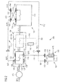
- FIG. 1 shows schematic drawing of an exemplary embodiment of a cooling system 100 of an internal combustion engine 102 wherein cooling system 100 is in a first cooling configuration.
- Internal combustion engine 102 includes a cylinder unit 114, such as, for example, a diesel, heavy fuel, or gas powered cylinder unit.
- Cylinder unit 114 may include a plurality of cylinders and a plurality of piston assemblies disposed within the cylinders (not shown). Cylinder unit 114 may include any number of cylinders, and the cylinders may be disposed in an "in-line" configuration, a "V" configuration, or in any other conventional configuration. Cylinder unit 114 may further include a cylinder head (not shown) configured to close the cylinder from on top, and a cylinder liner (not shown) configured to guide a piston of cylinder unit 114 during an up- and downward movement of the piston within the cylinder.
- internal combustion engine 102 includes a turbocharger 115 and a cooling system 100.
- Internal combustion engine 102 may further include other sub-systems and components not shown in Fig. 1 , such as a fuel supply system for supplying fuel to cylinder unit 114, an exhaust gas system for discharging exhaust gas of cylinder unit 114 to the environment, and a control unit for controlling operation of internal combustion engine 102.
- Turbocharger 115 is configured to receive ambient air, compress the ambient air and discharge charge air. By compressing the ambient air, a temperature of the ambient air may increase, for example, from about 25°C to about 260°C. Turbocharger 115 may further include a compressor (not shown) for compressing the ambient air, and a turbine (not shown) driven by exhaust gas of cylinder unit 114.
- Cooling system 100 includes a cooling circuit portion 104, a charge air cooler 106, a cylinder cooling jacket 108, a charge air cooler piping 110, a cylinder cooling jacket piping 112, and a cooling circuit portion connection piping 113, which together define a cooling circuit. Cooling system 100 may further include temperature sensors (not shown) for detecting a temperature of the coolant. Cooling system 100 is configured to cool internal combustion engine 102. Cooling circuit portion 104 is configured to supply and return coolant, such as water, to the remaining cooling circuit. Charge air cooler 106 is configured to cool charge air by transferring heat from charge air to the coolant.
- Cylinder cooling jacket 108 is configured to cool cylinder unit 114 by transferring heat produced during operation of internal combustion engine 102 from cylinder unit 114 to the coolant.
- Charge air cooler piping 110 is configured to connect charge air cooler 106 to cylinder cooling jacket 108.
- Cylinder cooling jacket piping 112 is configured to connect cylinder cooling jacket 108 to cooling circuit portion 104.
- cooling circuit portion connection piping 113 is configured to connect cooling circuit portion 104 to charge air cooler 106, thereby closing the cooling circuit.
- Cooling circuit portion 104 includes cooling circuit portion piping 116, a cooling circuit portion outlet 118, and a cooling circuit portion inlet 120.
- Cooling circuit portion piping 116 may be arranged at a distance from internal combustion engine 102.
- cooling circuit portion piping 116 may be arranged in a power plant, such as a combined heat and power plant, utilizing internal combustion engine 102 to provide thermal power and/or electric power.
- Cooling circuit portion piping 116 includes a fixed geometry and a fixed position in the power plant depending on the type and size of the power plant.
- Cooling circuit portion outlet 118 and cooling circuit portion inlet 120 may be disposed in the vicinity of internal combustion engine 102 supplying and returning coolant to the cooling circuit.
- Cooling circuit portion inlet 120 and cooling circuit portion outlet 118 have a fixed geometry and fixed position in the power plant depending on the type and size of the power plant.
- Cooling circuit portion 104 forms part of a secondary heating circuit 105, such as a district heating circuit. Cooling circuit portion 104 is in connection with secondary heating circuit 105 via a heat extraction system 122 disposed in cooling circuit portion piping 116. Heat extraction system 122 is configured to extract heat from the coolant and transfer that heat to secondary heating circuit 105 for either discharging the heat to the environment or recovering the heat for other applications, such as for heating applications, depending on the type and size of the power plant.
- heat extraction system 122 may be a heat recovery system 122 configured to recover heat of the coolant, for example, to provide hot water for heating applications.
- heat of the coolant may be discharged into the environment. This may be the case, for example, if the power plant is used in hot areas where no heating is required.
- heat extraction system 122 may be a heat discharge system 122 configured to discharge heat into the environment, for example, via a convection cooling.
- Heat discharge system 122 may, therefore, include one or more radiators having a large heat transfer area for efficiently transferring heat of the coolant to the atmosphere.
- secondary heating circuit 105 is, for example, a district heating circuit of a power plant or a communal heating circuit
- secondary heating circuit 105 may include a wide range of coolant temperatures at a coolant return port of heat extraction system 122.
- the range of temperatures may be between, for example, about 45°C and about 75°C.
- the coolant temperature at the coolant circuit portion outlet 118 may also cover a wide range of temperatures, depending on the coolant temperature of secondary heating circuit 105.
- the coolant temperature at cooling circuit portion outlet 118 may be in a range between, for example, about 60°C and about 80°C.
- charge air cooler 106 is configured to cool a flow of charge air admitted to charge air cooler 106 and transfer heat of the charge air to the coolant circulating in the cooling circuit.
- charge air cooler 106 may cool a flow of charge air from a temperature of 260°C to a temperature of 45°C.
- Charge air cooler 106 includes a cooling stage 124 with a top side 126 and a bottom side 128 opposite top side 126. Top and bottom sides 126, 128 together define a charge air passageway configured to guide charge air through charge air cooler 106, indicated by the arrow.
- Cooling stage 124 further includes a series of heat exchanging tubes (not shown) protruding at least partially into the charge air passageway.
- the heat exchanging tubes are configured to transfer heat from the charge air to the coolant by coolant running through the tubes and charge air flowing over the tubes.
- the heat exchanging tubes may be any type of heat exchanging tubes known to the person skilled in the art.
- the heat exchanging tubes may have any size, shape, length, geometry suitable for transferring heat from the charge air to the coolant.
- the heat exchanging tubes may be arranged in any layout with any center-to-center distance between adjoining tubes, and may have any outer surface and any inner surface suitable to efficiently transfer heat from the charge air to the coolant.
- Charge air cooler 106 further includes a first charge air cooler port 130 and a second charge air cooler port 132.
- first charge air cooler port 130 is disposed on bottom side 128 and second charge air cooler port 132 is disposed on top side 126. In some embodiments, this may however not be the case.
- first charge air cooler port 130 includes a first charge air cooler inlet 134 and a first charge air cooler outlet 136.
- second charge air cooler port 132 includes a second charge air cooler inlet 138 and a second charge air cooler outlet 140.
- First and second charge air cooler outlets 136, 140 are disposed downstream of first and second charge air cooler inlets 134, 138 with respect to a flow direction of charge air indicated by the arrow.
- first and second charge air cooler outlets 136, 140 may be disposed upstream of first and second charge air cooler inlets 134, 138 with respect to the flow direction of charge air.
- first and second charge air cooler outlets 136, 140 and first and second charge air cooler inlets 134, 138 may adjoin one another.
- first and second charge air cooler outlets 136, 140 as well as first and second charge air cooler inlets 134, 138 may each have the same connection geometry, the same size, the same height, etc.
- first and second charge air cooler outlets 136, 140 may be disposed symmetric to first and second charge air cooler inlets 134, 138 with respect to a plane extending perpendicular to the flow direction of charge air indicated by the arrow.
- first and second charge air cooler ports 130, 132 may also be symmetric to a mid-plane between top side 126 and bottom side 128 extending along the flow direction of charge air.
- charge air cooler 106 may, in principle, by rotated upside-down and still retain its connection geometry.
- charge air cooler 106 may be a two-stage charge air cooler 106 where cooling stage 124 as a first cooling stage configured to cool hot charge air from temperatures of, for example, 260°C to about 75°C, and a second cooling stage 142 configured to cool the charge air further, for example, from about 75°C to about 45°C.
- First cooling stage 124 may, therefore, constitute a high-temperature charge air cooling stage 124 and second cooling stage 142 may constitute a low-temperature charge air cooling stage 142.
- High-and low-temperature charge air cooling stages 124, 142 may form a compact unit, as indicated by the dashed-dotted box.
- low-temperature charge air cooling stage 142 may have the same connection layout and the same connection geometry as high-temperature charge air cooling stage 124.
- a rotation around a mid-plane between high- and low-temperature charge air cooling stages 124, 142 extending perpendicular to the flow direction of charge air may retain the connection geometry of charge air cooler 106.
- a heat transfer performance defined, for example, by a number of rows of heat exchanging tubes, of high-temperature charge air cooling stage 124 may be different to the heat transfer performance of low-temperature charge air cooling stage 142.
- a rotation of the two-stage charge air cooler as explained, also the heat transfer from the charge air to the coolant may change.
- a rotation of the two-stage charge air cooler may, therefore, allow for a higher flexibility in cooling internal combustion engine 102.
- Low-temperature charge air cooling stage 142 may further be connected to a low-temperature cooling circuit 144 including a low-temperature heat extraction system 146, for extracting heat transferred from the charge air to a coolant, such as water, circulating in low-temperature cooling circuit 144.
- a coolant such as water
- Cylinder cooling jacket 108 is configured to transfer heat produced in cylinder unit 114 to the coolant circulating in the cooling circuit.
- Cylinder cooling jacket 108 may be a jacket cooler produced by a series of holes, channels, or bores - either cast, milled, or drilled - for cooling the cylinder, cylinder liner, cylinder head, and other components of cylinder unit 114.
- Cylinder cooling jacket 108 includes a cylinder cooling jacket inlet 148 configured to admit the coolant to cylinder unit 114, and a cylinder cooling jacket outlet 150 for discharging the coolant.
- Cylinder cooling jacket 108 requires the coolant to have a narrow temperature range from, for example, about 75°C to about 95°C between cylinder cooling jacket inlet 148 and cylinder cooling jacket outlet 150 for efficiently cooling cylinder unit 114.
- Cylinder cooling jacket inlet and outlet 148, 150 further define a fixed flow direction of coolant within cylinder unit 114 from cylinder cooling jacket inlet 148 to cylinder cooling jacket outlet 150.
- Cylinder cooling jacket inlet and outlet 148, 150 have a fixed position within internal combustion engine 102 due to spatial requirements within internal combustion engine 102. Cylinder cooling jacket inlet and outlet 148, 150 may further have identical connection geometry, but not necessarily.
- the coolant is shown to have a coolant outlet temperature at cooling circuit portion outlet 118 of about 60°C.
- a coolant outlet temperature corresponds, for example, to a combined heat and power plant where the coolant of secondary heating circuit 105 has a temperature of, for example, 50°C at the coolant return port of heat extraction system 122.
- the coolant may still be able to increase its temperature and still not violate the narrow temperature range requirement defined by cylinder cooling jacket 108.
- the coolant when the coolant exits cooling circuit portion outlet 118 at a temperature of about 60°C, the coolant may increase its temperature by cooling charge air in charge air cooler 106, and still have a coolant temperature close to the required cylinder cooling jacket inlet temperature.
- the coolant temperature may be about 80°C upon entering cylinder cooling jacket inlet 148, as indicated in Fig. 1 .
- the cooling system 100 is configured in the first cooling configuration, as exemplarily shown in Fig. 1 , such that coolant supplied by cooling circuit portion outlet 118 first passes charge air cooler 106 and then cylinder cooling jacket 108.
- cooling circuit portion outlet 118 is connected to first charge air cooler port 130 via cooling circuit portion connection piping 113.
- first charge air cooler port 130 includes first charge air cooler inlet and outlet 134, 136, as illustrated in Fig. 1
- cooling circuit portion outlet 118 is connected to first charge air cooler inlet 134.
- the coolant then passes charge air cooler 106 and exits charge air cooler 106 at second charge air cooler outlet 140.
- the coolant may increase its temperature, for example, from about 60°C to about 80°C.
- Charge air cooler 106 is connected to cylinder cooling jacket 108 via charge air cooler piping 110.
- Charge air cooler piping 110 includes a first charge air cooler piping element 152, a second charge air cooler piping element 154, and a third charge air cooler piping element 156.
- First charge air cooler piping element 152 is connected to second charge air cooler piping element 154 via a first charge air cooler connection portion 158.
- Second charge air cooler piping element 154 is connected to third charge air cooler piping element 156 via a second charge air cooler connection portion 160.
- First and second charge air cooler connection portions 158, 160 may include flanges welded or soldered onto first, second, and third charge air cooler piping elements 152, 154, 156, or may include pipe couplings, pipe fittings, etc., screwed, soldered, welded, press-fitted onto first, second, and third charge air cooler piping elements 152, 154, 156.
- First and second charge air cooler connection portions 158, 160 may further include any type of sealing, such as a gasket sealing, an O-ring sealing or the like.
- First, second, and third charge air cooler piping elements 152, 154, 156 may further be non-detachably connected to each other at first and second charge air cooler connection portions 158, 160, respectively, via welding, soldering, riveting, glueing, etc., or may be detachably connected to each other via screws, bolts, clamps, pipe-in-pipe connections, etc.
- first and second charge air cooler connection portions 158, 160 may be non-detachably connected to internal combustion engine 102, for example, welded, soldered glued, etc. or may be detachably connected to internal combustion engine 102 via flanges, webs or the like.
- first charge air cooler piping element 152 is connected to second charge air cooler port 132 and to first charge air cooler connection portion 158.
- first charge air cooler piping element 152 is connected to second charge air cooler outlet 140 and to first charge air cooler connection portion 158.
- Second charge air cooler piping element 154 is connected to first charge air cooler connection portion 158 and to second charge air cooler connection portion 160.
- third charge air cooler piping element 156 is connected to second charge air cooler connection portion 160 and to cylinder cooling jacket inlet 148.
- Cylinder cooling jacket 108 is connected to cooling circuit portion 104 via cylinder cooling jacket piping 112.
- Cylinder cooling jacket piping 112 includes a first cylinder cooling jacket piping element 162, a second cylinder cooling jacket piping element 164, and a third cylinder cooling jacket piping element 166.
- First cylinder cooling jacket piping element 162 is connected to second cylinder cooling jacket piping element 164 via a first cylinder cooling jacket connection portion 168.
- Second cylinder cooling jacket piping element 164 is connected to third cylinder cooling jacket piping element 166 via a second cylinder cooling jacket connection portion 170.
- First and second cylinder cooling jacket connection portions 168, 170 may include the same shapes, geometries, connection means, etc., as first and second charge air cooler connection portions 158, 160, or more generally may be identical to first and second charge air cooler connection portions 158, 160. In some embodiments, first and second cylinder cooling jacket connection portions 168, 170 may be different to first and second charge air cooler connection portions 158, 160. Moreover, first and second cylinder cooling jacket connection portions 168, 170 may be detachably or non-detachably connected to internal combustion engine 102 via flanges, webs or the like.
- first cylinder cooling jacket piping element 162 is connected to cylinder cooling jacket outlet 150 and to first cylinder cooling jacket connection portion 168.
- Second cylinder cooling jacket piping element 164 is connected to first cylinder cooling jacket connection portion 168 and to second cylinder cooling jacket connection portion 170.
- third cylinder cooling jacket piping element 166 is connected to second cylinder cooling jacket connection portion 170 and to cooling circuit portion inlet 120, thereby closing the cooling circuit.
- Third charge air cooler piping element 156 and first cylinder cooling jacket piping element 162 may be separate pipes or may be a direct-pipe unit 200, as indicated by the dashed-dotted box.
- Direct-pipe unit 200 may include third charge air cooler piping element 156 and first cylinder cooling jacket piping element 162 welded to one another, or cast to shape.
- Direct-pipe unit 200 may further include a first common flange for connecting to second charge air cooler connection portion 160 and to first cylinder cooling jacket connection portion 168, and may include a second common flange for connecting to cylinder cooling jacket inlet 148 and to cylinder cooling jacket outlet 150.
- direct-pipe unit 200 may include one common flange on one side and two separate flanges on the other side.
- cooling system 100 is schematically shown, wherein cooling system 100 is configured in a second cooling configuration. Elements already explained in connection with Fig. 1 have the same reference numerals.
- the coolant is shown to have a coolant outlet temperature at cooling circuit portion outlet 118 of about 75°C.
- Such coolant outlet temperatures correspond, for example, to power plants in hot areas where no heating applications are required and the coolant circulating in secondary heating circuit 105 has a coolant temperature at the coolant return port of heat extraction system 122 of, for example, 65°C, as indicated in Fig. 2 .
- the coolant may not be utilized for removing heat from hot charge air prior to entering cylinder cooling jacket 108 without violating the narrow temperature range restriction of cylinder cooling jacket 108.
- cylinder unit 114 might not be efficiently cooled, and, as a result, internal combustion engine 102 might produce a larger amount of exhaust emissions or would require more fuel to provide a desired power output.
- the cooling system 100 is configured in the second cooling configuration, as exemplarily shown in Fig. 2 , such that coolant supplied by cooling circuit portion outlet 118 first passes cylinder cooling jacket 102 and then charge air cooler 106.
- cooling circuit portion outlet 118 is connected to second cylinder cooling jacket connection portion 170 via third cylinder cooling jacket piping element 166.
- Second cylinder cooling jacket piping element 164 is connected to second cylinder cooling jacket connection portion 170 and to first cylinder cooling jacket connection portion 168.
- first cylinder cooling jacket piping element 162 is connected to first cylinder cooling jacket connection portion 168 and to cylinder cooling jacket inlet 148.
- Cylinder cooling jacket outlet 150 is then connected to second charge air cooler connection portion 160 via third charge air cooler piping element 156.
- Second charge air cooler piping element 154 is connected to second charge air cooler connection portion 160 and to first charge air cooler connection portion 158.
- first charge air cooler piping element 152 is connected to first charge air cooler connection portion 158 and to second charge air cooler port 132.
- second charge air cooler port 132 includes second charge air cooler inlet and outlet 138, 140, as illustrated in Fig. 1
- first charge air cooler piping element 152 is connected to first charge air cooler connection portion 158 and to second charge air cooler inlet 138.
- the coolant then passes charge air cooler 106, thereby removing heat from the hot charge air and increasing the coolant temperature, for example, from about 85°C to about 105°C.
- the temperature of charge air may be reduced from, for example, about 260°C to about 95°C.
- First charge air cooler port 130 is then connected to cooling circuit portion inlet 120 via cooling circuit portion connection piping 113, thereby closing the cooling circuit.
- first charge air cooler port 130 includes first charge air cooler inlet and outlet 134, 136, as illustrated in Fig. 1
- first charge air cooler outlet 136 is connected to cooling circuit portion inlet 120 via cooling circuit portion connection piping 113.
- First and second charge air cooler piping elements 152, 154, second and third cylinder cooling jacket piping elements 164, 166, cooling circuit portion piping 116 and cooling circuit portion connection piping 113 may be rigid piping made from, for example, steel or iron, or may be flexible piping made from, for example, temperature-resistant plastics or layers of plastic and steel.
- the piping may be detachably or non-detachably connected to internal combustion engine 102 using appropriate connection means such as welding, soldering, clamps, screws, bolts, or the like.
- first cylinder cooling jacket piping element 162 and third charge air cooler piping element 156 are arranged in a cross-like flow configuration.
- First cylinder cooling jacket piping element 162 and third charge air cooler piping element 156 may, again, be separate pipes or may be integrally formed as a cross-pipe unit 300, as indicated by the dashed-dotted box.
- Fig. 3 shows an exemplary embodiment of such a cross-pipe unit 300 combining first cylinder cooling jacket piping element 162 and third charge air cooler piping element 156 in a cross-like flow configuration.
- Cross-pipe unit 300 includes a main body 301 extending along a longitudinal axis A separating main body 301 into a first portion 302 and a second portion 303.
- Main body 301 includes a cross-pipe unit top side 320 having a first opening 304 and a second opening 306, and a cross-pipe unit bottom side 322 opposite cross-pipe unit top side 320 having a third opening 308 and a fourth opening 310.
- First opening 304 and third opening 308 are disposed in the first portion 302, second opening 306 and fourth opening 310 are disposed in the second portion 303.
- Cross-pipe unit 300 further includes a first channel 312 connecting first opening 304 to third opening 310, and a second channel 314 connecting second opening 306 to fourth opening 308.
- first channel 312 connecting first opening 304 to fourth opening 310 directs a flow of fluid from first portion 302 to second portion 306.
- second opening 306 is disposed in second portion 303 and third opening 308 is disposed in the first portion 302 with respect to longitudinal axis A
- second channel 314 connecting second opening 306 to fourth opening 308 directs a flow of fluid from second portion 303 to first portion 302, thereby arriving at a cross-like flow configuration between first channel 312 and second channel 314.
- First to fourth openings 304, 306, 308, 310 include a circular cross-section. In some embodiments, first to fourth openings 304, 306, 308, 310 may include non-circular cross-sections, such as oval, rectangular cross-sections, etc.
- First opening 304 and second opening 306 are disposed along a first common axis B.
- third opening 308 and fourth opening 310 are disposed along a second common axis C.
- First and second common axes B, C are disposed in a common plane extending along longitudinal axis A and including longitudinal axis A. In some embodiments, first and second common axes B, C may not be disposed in the common plane extending along longitudinal axis A and including longitudinal axis A.
- Cross-pipe unit 300 further includes a first flange 316 formed on cross-pipe unit top side 320 and a second flange 318 formed on cross-pipe unit bottom side 322.
- First opening 304 and second opening 306 are disposed in first flange 316.
- Third opening 308 and fourth opening 310 are disposed in second flange 318.
- First flange 316 is configured to connect to first cylinder cooling jacket connection portion 168 and to second charge air cooler connection portion 160, such that second cylinder cooling jacket piping element 164 is in fluid connection with first opening 304, and second charge air cooler piping element 154 is in fluid connection with second opening 306.
- Second flange 318 is configured to connect to cylinder cooling jacket outlet 150 and to cylinder cooling jacket inlet 148, such that cylinder cooling jacket outlet 150 is in fluid connection with third opening 308 and cylinder cooling jacket inlet 148 is in fluid connection with fourth opening 310.
- First flange 316 and second flange 318 include a rectangular shape. In some embodiments, first and second flanges 316, 318 may include circular shapes or oval shapes. First flange 316 may be connected detachably or non-detachably to second charge air cooler connection portion 160 and first cylinder cooling jacket connection portion 168 using appropriate connection means.
- second flange 318 may be connected detachably or non-detachably to cylinder cooling jacket inlet 148 and cylinder cooling jacket outlet 150 using appropriate connection means.
- First flange 316 extends non-parallel to second flange 318.
- first and second flanges 316, 318 may be parallel to one another.
- Cross-pipe unit 300 may further include other features not shown, for example, webs, flanges, etc. for connecting cross-pipe unit 300 to internal combustion engine 102.
- Cross-pipe unit 300 may be cast and may be made from rigid material, such as steel, iron or cast iron.
- cross-pipe unit 300 may be made from flexible material, such as temperature-resistant plastics or layers of plastic and steel.
- Exemplary internal combustion engines suited to the disclosed cooling system are internal combustion engines of any type, such as those manufactured by Caterpillar Motoren GmbH & Co. KG, Kiel, Germany. Respective internal combustion engines may be operated at speeds of 400 - 1200 rpm and may be applied, for example, in landbased power generator sets. One skilled in the art will however appreciate that the disclosed cooling system may also be adapted to suit other internal combustion engines.
- Fig. 4 shows a schematic flow diagram of an exemplary strategy for configuring cooling system 100 for internal combustion engine 102.
- a coolant outlet temperature T out is determined at cylinder cooling jacket outlet 150 or, as indicated in Fig. 4 , downstream of cylinder cooling jacket outlet 150 with respect to the flow direction of the coolant.
- a temperature sensor is disposed at cylinder cooling jacket outlet 150 or downstream of cylinder cooling jacket outlet 150 and configured to sense a temperature of the coolant.
- both cooling configurations are tested and a first coolant outlet temperature in the first cooling configuration during operation of internal combustion engine 102 is determined.
- a second coolant outlet temperature in the second cooling configuration during operation of internal combustion engine is determined.
- just one coolant outlet temperature is determined.
- Threshold outlet temperature T thr may be, for example, about 92°C and corresponds to a coolant temperature at which internal combustion engine 102 is able to provide its full range of desired power outputs. That means, at step 402, it is determined whether the first coolant outlet temperature exceeds a first threshold outlet temperature. And it is determined whether the second coolant outlet temperature exceeds a second threshold outlet temperature.
- the first and second threshold outlet temperatures are identical to threshold outlet temperature T thr . In some embodiments, the first and second threshold outlet temperatures may be different from T thr and/or may be non-equal to one another.
- cooling system 100 is then configured in the first cooling configuration, as exemplarily shown in Fig. 1 and illustrated on the left-hand side of Fig. 4 . That means, charge air cooler 106 and cylinder cooling jacket 108 are connected to cooling circuit portion 104 such that the flow of coolant first enters charge air cooler 106 and then passes cylinder cooling jacket 108. The coolant then leaves cylinder cooling jacket 108 and returns to cooling circuit portion 104, thereby closing the cooling circuit.
- cooling system 100 By configuring cooling system 100 in the first cooling configuration, the coolant first extracts heat from hot charge air and then from cylinder unit 114. Thus, upon entering charge air cooler 106, the coolant temperature is low, and, therewith, a heat transfer between the cold coolant and the hot charge air is high. As a consequence, by using the first cooling configuration, a high thermal efficiency may be achieved.
- the first cooling configuration may be chosen, for example, in combined heat and power plants, where the heat of the coolant is recovered for heating applications or the like.
- cooling system 100 is then configured in the second cooling configuration, as exemplarily shown in Fig. 2 and illustrated on the right-hand side of Fig. 4 . That means, charge air cooler 106 and cylinder cooling jacket 108 are connected to cooling circuit portion 104 such that the flow of coolant first enters cylinder cooling jacket 108 and then charge air cooler 106. The coolant then leaves charge air cooler 106 and returns to cooling circuit portion 104, thereby closing the cooling circuit.
- cooling system 100 By configuring cooling system 100 in the second cooling configuration, the coolant first extracts heat from cylinder unit 114, thereby ensuring that the coolant inlet temperature at cylinder cooling jacket inlet 148 is within the narrow temperature range required by cylinder cooling jacket 108. Once the coolant leaves cylinder cooling jacket 108, the flow of coolant than enters charge air cooler 106, thereby cooling hot charge air.
- the coolant temperature may increase, for example, from temperatures of about 90°C at cylinder cooling jacket outlet 150 to about 105°C at second charge air cooler port 132.
- a coolant temperature at heat recovery system 122 may be increased, for example, from about 90°C in the first cooling configuration to about 105°C in the second cooling configuration.
- the second cooling configuration may be chosen, for example, in power plants located in hot areas, where the heat of the coolant is not used for heating purposes but discharged into the environment.
- cooling system 100 is configured such that charge air cooler 106 is arranged upstream of cylinder cooling jacket 108 with respect to the flow direction of coolant defined by the flow of coolant from cooling circuit portion inlet 120 to coolant circuit portion outlet 118.
- cooling system 100 is configured such that charge air cooler 106 is arranged downstream of cylinder cooling jacket 108 with respect to the same flow direction of coolant.
- a preferred cooling configuration for internal combustion engine 102 may be chosen.
- the described cooling strategy may be also applicable, for example, for coolant inlet temperatures T in at cooling circuit portion outlet 118 in a range from, for example, about 70°C to about 80°C or coolant inlet temperatures T in at the coolant return port of heat extraction system 122 in a range from, for example, about 60°C to about 70°C , where a desired operation of internal combustion engine 102 may depend on the chosen cooling configuration.
- both cooling configurations may be configured using a minimized amount of costs and a minimized amount of effort. That means, in both cooling configurations cooling circuit portion 104, cooling circuit portion outlet 118, cooling circuit portion inlet 120, second charge air cooler piping element 154, and second cylinder cooling jacket piping element 164 are utilized in both configurations. Thus, there is no need to change those components, and those components may remain fixed within cooling system 100 for any of the cooling configurations. Also, in the first cooling configuration direct-pipe unit 200 is utilized and in the second cooling configuration cross-pipe unit 300 is utilized.
- the first cooling configuration is changed into the second cooling configuration using a minimized amount of costs and a minimized amount of effort.
- the proposed cooling system 100 may, therefore, be adapted to the application at hand at a minimized amount of components to be exhchanged.
- the herein described cooling system and strategy for configuring a cooling system for an internal combustion engine may be applicable to any internal combustion engine operating in electric power generation plants and/or combined heat and power generation plants located in hot and cold areas.
Landscapes
- Engineering & Computer Science (AREA)
- Chemical & Material Sciences (AREA)
- Combustion & Propulsion (AREA)
- Mechanical Engineering (AREA)
- General Engineering & Computer Science (AREA)
- Physics & Mathematics (AREA)
- Thermal Sciences (AREA)
- Cylinder Crankcases Of Internal Combustion Engines (AREA)
Abstract
Description
- The present disclosure relates to a cooling system for an internal combustion engine, and more particularly to a cooling system for a turbocharged internal combustion engine.
- Cylinder cooling jackets for internal combustion engines usually require a coolant medium to be within a narrow temperature range at the inlet of the cylinder cooling jacket such that the internal combustion engine operates as desired. For example, is the inlet temperature too high, the engine block including the cylinder unit, cylinder liner and cylinder head may not be cooled as desired, and, as a result, the engine may produce more exhaust emissions or require a higher amount of fuel to provide a desired power output.
- Cylinder cooling jackets are often connected in a cooling circuit to other components of the engine cooling system, such as to a charge air cooler configured to cool charge air of a turbocharger. For a desired operation of the internal combustion engine, the charge air should have a low inlet temperature at the cylinder unit.
- The demand for a low temperature of the charge air and the demand for a low temperature of the coolant medium at the inlet of the cylinder unit are, however, two contradicting demands. To meet those demands, currently, two separate cooling systems for internal combustion engines are required. Thus, the internal combustion engine is equipped with either a cooling system tuned to achieve a low coolant medium inlet temperature, or a cooling system tuned to achieve a low charge air inlet temperature.
- The present disclosure is directed, at least in part, to improving or overcoming one or more aspects of prior systems.
- According to an aspect of the present disclosure, a cooling system for an internal combustion engine including a cylinder unit is disclosed. The cooling system comprises a cooling circuit portion configured to circulate a flow of coolant. The cooling circuit portion includes a cooling circuit portion outlet and a cooling circuit portion inlet. The cooling circuit portion outlet and the cooling circuit portion inlet define a flow direction of coolant within the cooling circuit portion from the cooling circuit portion inlet to the cooling circuit portion outlet. The cooling system further comprises a charge air cooler configured to transfer heat from charge air to the coolant. The charge air cooler includes a first charge air cooler port and a second charge air cooler port. The cooling system further comprises a cylinder cooling jacket configured to transfer heat from the cylinder unit to the coolant. The cylinder cooling jacket includes a cylinder cooling jacket inlet and a cylinder cooling jacket outlet. In a first cooling configuration of the cooling system, the cooling circuit portion outlet is connected to the first charge air cooler port, the second charge air cooler port is connected to the cylinder cooling jacket inlet, and the cylinder cooling jacket outlet is connected to the cooling circuit portion inlet. In a second cooling configuration of the cooling system, the cooling circuit portion outlet is connected to the cylinder cooling jacket inlet, the cylinder cooling jacket outlet is connected to the second charge air cooler port, and the first charge air cooler port is connected to the cooling circuit portion inlet.
- According to another aspect of the present disclosure, a set of interchangeable pipe units for configuring a cooling system of an internal combustion engine in a first cooling configuration and in a second cooling configuration is disclosed. The cooling system includes a charge air cooler piping with a first charge air cooler connection portion and a second charge air cooler connection portion, a cylinder cooling jacket with a cylinder cooling jacket inlet and a cylinder cooling jacket outlet, and a cylinder cooling jacket piping with a first cylinder cooling jacket connection portion and a second cylinder cooling jacket connection portion. The set of interchangeable pipe units includes a direct-pipe unit and a cross-pipe unit. In the first cooling configuration, the direct-pipe unit is configured to connect the second charge air cooler connection portion to the cylinder cooling jacket inlet, and the cylinder cooling jacket outlet to the first cylinder cooling jacket connection portion. In the second cooling configuration, the cross-pipe unit is configured to connect the cylinder cooling jacket inlet to the first cylinder cooling jacket connection portion, and the cylinder cooling jacket outlet to the second charge air cooler connection portion.
- According to another aspect of the present disclosure, an internal combustion engine is disclosed. The internal combustion engine comprises a cylinder unit, a turbocharger configured to provide charge air to the cylinder unit, and a cooling system as exemplary disclosed herein.
- According to another aspect of the present disclosure, a method for configuring a cooling system for an internal combustion engine is disclosed. The cooling system includes a cooling circuit portion, a charge air cooler, and a cylinder cooling jacket with a cylinder cooling jacket inlet and a cylinder cooling jacket oulet. The cooling system further includes a first cooling configuration and a second cooling configuration. The method comprises determining a first coolant outlet temperature at the cylinder cooling jacket oulet for the first cooling configuration. The method further comprises determining a second coolant outlet temperature at the cylinder cooling jacket outlet for the second cooling configuration. The method further comprises configuring the cooling system in the second cooling configuration if the first coolant outlet temperature exceeds a first threshold outlet temperature. The method further comprises configuring the cooling system in the first cooling configuration if the second coolant outlet temperature does not exceed a second threshold outlet temperature.
- Other features and aspects of this disclosure will be apparent from the following description and the accompanying drawings.
- The accompanying drawings, which are incorporated herein and constitute a part of the specification, illustrate exemplary embodiments of the disclosure and, together with the description, serve to explain the principles of the disclosure. In the drawings:
-
Fig. 1 shows a schematic drawing of an exemplary cooling system for cooling an internal combustion engine wherein the cooling system is in a first cooling configuration; -
Fig. 2 shows a schematic drawing of an exemplary cooling system for cooling an internal combustion engine wherein the cooling system is in a second cooling configuration; -
Fig. 3 shows an exemplary embodiment of a cross-pipe unit used in the cooling system in the second cooling configuration; and -
Fig. 4 shows a schematic flow diagram of an exemplary strategy for configuring a cooling system for an internal combustion engine. - The following is a detailed description of exemplary embodiments of the present disclosure. The exemplary embodiments described therein and illustrated in the drawings are intended to teach the principles of the present disclosure, enabling those of ordinary skill in the art to implement and use the present disclosure in many different environments and for many different applications. Therefore, the exemplary embodiments are not intended to be, and should not be considered as, a limiting description of the scope of patent protection. Rather, the scope of patent protection shall be defined by the appended claims.
- The present disclosure is based in part on the realization that a single, modular cooling system for an internal combustion engine may be able to provide both a low charge air temperature and a required coolant temperature at the cylinder cooling jacket inlet.
- The present disclosure is further at least partly based on the realization that the single, modular cooling system may be configured in two cooling configurations to meet both demands for a wide range of coolant supply temperatures. For low coolant supply temperatures of, for example, 60°C, the modular cooling system may be configured in a first cooling configuration, where the charge air cooler may be arranged downstream of the cylinder cooling jacket with respect to a flow direction of coolant, thereby increasing a thermal heat transfer between the cold coolant and the hot charge air. For high coolant supply temperatures of, for example, 75°C or more, the modular cooling system may be configured in a second cooling configuration, where the cylinder cooling jacket may be arranged upstream of the charge air cooler with respect to the flow direction of coolant, thereby ensuring that the coolant inlet temperature at the cylinder cooling jacket corresponds to the required coolant inlet temperature despite the high coolant supply temperature.
- The present disclosure is further at least partly based on the realization that in both cooling configurations a coolant supply port, a coolant return port, a flow direction of coolant between the coolant supply and coolant return ports, a flow direction of coolant within the cylinder cooling jacket, and any secondary cooling circuit, such as district heating circuits of the cooling system may be the same for the first and the second cooling configuration.
- The present disclosure is further at least partly based on the realization that both cooling configurations may be achieved using on-engine modifications only, which may reduce costs and efforts to provide both a low charge air temperature and a low coolant temperature at the cylinder cooling jacket inlet over the wide range of coolant supply temperatures.
- Referring now to the drawings,
Fig. 1 shows schematic drawing of an exemplary embodiment of acooling system 100 of aninternal combustion engine 102 whereincooling system 100 is in a first cooling configuration. -
Internal combustion engine 102 includes acylinder unit 114, such as, for example, a diesel, heavy fuel, or gas powered cylinder unit.Cylinder unit 114 may include a plurality of cylinders and a plurality of piston assemblies disposed within the cylinders (not shown).Cylinder unit 114 may include any number of cylinders, and the cylinders may be disposed in an "in-line" configuration, a "V" configuration, or in any other conventional configuration.Cylinder unit 114 may further include a cylinder head (not shown) configured to close the cylinder from on top, and a cylinder liner (not shown) configured to guide a piston ofcylinder unit 114 during an up- and downward movement of the piston within the cylinder. - Multiple sub-systems may be included in
internal combustion engine 102 to support combustion processes incylinder unit 114. Among others,internal combustion engine 102 includes aturbocharger 115 and acooling system 100.Internal combustion engine 102 may further include other sub-systems and components not shown inFig. 1 , such as a fuel supply system for supplying fuel tocylinder unit 114, an exhaust gas system for discharging exhaust gas ofcylinder unit 114 to the environment, and a control unit for controlling operation ofinternal combustion engine 102. - Turbocharger 115 is configured to receive ambient air, compress the ambient air and discharge charge air. By compressing the ambient air, a temperature of the ambient air may increase, for example, from about 25°C to about 260°C. Turbocharger 115 may further include a compressor (not shown) for compressing the ambient air, and a turbine (not shown) driven by exhaust gas of
cylinder unit 114. -
Cooling system 100 includes acooling circuit portion 104, acharge air cooler 106, acylinder cooling jacket 108, a charge aircooler piping 110, a cylindercooling jacket piping 112, and a cooling circuit portion connection piping 113, which together define a cooling circuit.Cooling system 100 may further include temperature sensors (not shown) for detecting a temperature of the coolant.Cooling system 100 is configured to coolinternal combustion engine 102.Cooling circuit portion 104 is configured to supply and return coolant, such as water, to the remaining cooling circuit.Charge air cooler 106 is configured to cool charge air by transferring heat from charge air to the coolant.Cylinder cooling jacket 108 is configured to coolcylinder unit 114 by transferring heat produced during operation ofinternal combustion engine 102 fromcylinder unit 114 to the coolant. Charge aircooler piping 110 is configured to connectcharge air cooler 106 tocylinder cooling jacket 108. Cylinder cooling jacket piping 112 is configured to connectcylinder cooling jacket 108 to coolingcircuit portion 104. And cooling circuit portion connection piping 113 is configured to connectcooling circuit portion 104 to chargeair cooler 106, thereby closing the cooling circuit. -
Cooling circuit portion 104 includes cooling circuit portion piping 116, a coolingcircuit portion outlet 118, and a coolingcircuit portion inlet 120. Cooling circuit portion piping 116 may be arranged at a distance frominternal combustion engine 102. For example, cooling circuit portion piping 116 may be arranged in a power plant, such as a combined heat and power plant, utilizinginternal combustion engine 102 to provide thermal power and/or electric power. Cooling circuit portion piping 116 includes a fixed geometry and a fixed position in the power plant depending on the type and size of the power plant. Coolingcircuit portion outlet 118 and coolingcircuit portion inlet 120 may be disposed in the vicinity ofinternal combustion engine 102 supplying and returning coolant to the cooling circuit. Coolingcircuit portion inlet 120 and coolingcircuit portion outlet 118 have a fixed geometry and fixed position in the power plant depending on the type and size of the power plant. - Coolant exits cooling circuit portion piping 116 at cooling
circuit portion outlet 118 for circulation through cooling circuit portion connection piping 113, charge aircooler piping 110, cylinder coolingjacket piping 112,charge air cooler 106, andcylinder cooling jacket 108, and returns to cooling circuit portion piping 116 via coolingcircuit portion inlet 120, thereby circulating in the cooling circuit. -
Cooling circuit portion 104 forms part of asecondary heating circuit 105, such as a district heating circuit.Cooling circuit portion 104 is in connection withsecondary heating circuit 105 via aheat extraction system 122 disposed in cooling circuit portion piping 116.Heat extraction system 122 is configured to extract heat from the coolant and transfer that heat tosecondary heating circuit 105 for either discharging the heat to the environment or recovering the heat for other applications, such as for heating applications, depending on the type and size of the power plant. - For example, if the power plant is a combined heat and power plant, the heat of the coolant is transferred to
secondary heating circuit 105 viaheat extraction system 122 for heating other components of the power plant. In those applications,heat extraction system 122, may be aheat recovery system 122 configured to recover heat of the coolant, for example, to provide hot water for heating applications. - In other power plants, heat of the coolant may be discharged into the environment. This may be the case, for example, if the power plant is used in hot areas where no heating is required. In those applications,
heat extraction system 122 may be aheat discharge system 122 configured to discharge heat into the environment, for example, via a convection cooling.Heat discharge system 122 may, therefore, include one or more radiators having a large heat transfer area for efficiently transferring heat of the coolant to the atmosphere. - As
secondary heating circuit 105 is, for example, a district heating circuit of a power plant or a communal heating circuit,secondary heating circuit 105 may include a wide range of coolant temperatures at a coolant return port ofheat extraction system 122. The range of temperatures may be between, for example, about 45°C and about 75°C. As a consequence, the coolant temperature at the coolantcircuit portion outlet 118 may also cover a wide range of temperatures, depending on the coolant temperature ofsecondary heating circuit 105. Thus, the coolant temperature at coolingcircuit portion outlet 118 may be in a range between, for example, about 60°C and about 80°C. - Referring again to
Fig. 1 ,charge air cooler 106 is configured to cool a flow of charge air admitted to chargeair cooler 106 and transfer heat of the charge air to the coolant circulating in the cooling circuit. For example,charge air cooler 106 may cool a flow of charge air from a temperature of 260°C to a temperature of 45°C. -
Charge air cooler 106 includes acooling stage 124 with atop side 126 and abottom side 128 oppositetop side 126. Top andbottom sides charge air cooler 106, indicated by the arrow. Coolingstage 124 further includes a series of heat exchanging tubes (not shown) protruding at least partially into the charge air passageway. The heat exchanging tubes are configured to transfer heat from the charge air to the coolant by coolant running through the tubes and charge air flowing over the tubes. The heat exchanging tubes may be any type of heat exchanging tubes known to the person skilled in the art. The heat exchanging tubes may have any size, shape, length, geometry suitable for transferring heat from the charge air to the coolant. The heat exchanging tubes may be arranged in any layout with any center-to-center distance between adjoining tubes, and may have any outer surface and any inner surface suitable to efficiently transfer heat from the charge air to the coolant. -
Charge air cooler 106 further includes a first charge air cooler port 130 and a second charge aircooler port 132. Depending on the type and design ofcharge air cooler 106, first charge air cooler port 130 is disposed onbottom side 128 and second charge aircooler port 132 is disposed ontop side 126. In some embodiments, this may however not be the case. In some embodiments, as exemplarily shown inFig. 1 , first charge air cooler port 130 includes a first charge aircooler inlet 134 and a first charge aircooler outlet 136. Likewise, in some embodiments, as exemplarily shown inFig. 1 , second charge aircooler port 132 includes a second charge aircooler inlet 138 and a second charge aircooler outlet 140. First and second charge aircooler outlets cooler inlets cooler outlets cooler inlets cooler outlets cooler inlets cooler outlets cooler inlets cooler outlets cooler inlets cooler ports 130, 132 may also be symmetric to a mid-plane betweentop side 126 andbottom side 128 extending along the flow direction of charge air. Thus, in some embodiments,charge air cooler 106 may, in principle, by rotated upside-down and still retain its connection geometry. - In some embodiments,
charge air cooler 106 may be a two-stagecharge air cooler 106 where coolingstage 124 as a first cooling stage configured to cool hot charge air from temperatures of, for example, 260°C to about 75°C, and asecond cooling stage 142 configured to cool the charge air further, for example, from about 75°C to about 45°C.First cooling stage 124 may, therefore, constitute a high-temperature chargeair cooling stage 124 andsecond cooling stage 142 may constitute a low-temperature chargeair cooling stage 142. High-and low-temperature charge air cooling stages 124, 142 may form a compact unit, as indicated by the dashed-dotted box. Moreover, low-temperature chargeair cooling stage 142 may have the same connection layout and the same connection geometry as high-temperature chargeair cooling stage 124. Thus, in principle, also a rotation around a mid-plane between high- and low-temperature charge air cooling stages 124, 142 extending perpendicular to the flow direction of charge air may retain the connection geometry ofcharge air cooler 106. - In some embodiments, a heat transfer performance defined, for example, by a number of rows of heat exchanging tubes, of high-temperature charge
air cooling stage 124 may be different to the heat transfer performance of low-temperature chargeair cooling stage 142. Thus, by a rotation of the two-stage charge air cooler, as explained, also the heat transfer from the charge air to the coolant may change. A rotation of the two-stage charge air cooler may, therefore, allow for a higher flexibility in coolinginternal combustion engine 102. - Low-temperature charge
air cooling stage 142 may further be connected to a low-temperature cooling circuit 144 including a low-temperatureheat extraction system 146, for extracting heat transferred from the charge air to a coolant, such as water, circulating in low-temperature cooling circuit 144. -
Cylinder cooling jacket 108 is configured to transfer heat produced incylinder unit 114 to the coolant circulating in the cooling circuit.Cylinder cooling jacket 108 may be a jacket cooler produced by a series of holes, channels, or bores - either cast, milled, or drilled - for cooling the cylinder, cylinder liner, cylinder head, and other components ofcylinder unit 114.Cylinder cooling jacket 108 includes a cylinder coolingjacket inlet 148 configured to admit the coolant tocylinder unit 114, and a cylindercooling jacket outlet 150 for discharging the coolant.Cylinder cooling jacket 108 requires the coolant to have a narrow temperature range from, for example, about 75°C to about 95°C between cylinder coolingjacket inlet 148 and cylinder coolingjacket outlet 150 for efficiently coolingcylinder unit 114. Cylinder cooling jacket inlet andoutlet cylinder unit 114 from cylinder coolingjacket inlet 148 to cylinder coolingjacket outlet 150. Cylinder cooling jacket inlet andoutlet internal combustion engine 102 due to spatial requirements withininternal combustion engine 102. Cylinder cooling jacket inlet andoutlet - Referring again to cooling
circuit portion 104, exemplarily the coolant is shown to have a coolant outlet temperature at coolingcircuit portion outlet 118 of about 60°C. Such a coolant outlet temperature corresponds, for example, to a combined heat and power plant where the coolant ofsecondary heating circuit 105 has a temperature of, for example, 50°C at the coolant return port ofheat extraction system 122. In cases where the coolant outlet temperature at coolingcircuit portion outlet 118 is around 60°C, the coolant may still be able to increase its temperature and still not violate the narrow temperature range requirement defined bycylinder cooling jacket 108. In other words, when the coolant exits coolingcircuit portion outlet 118 at a temperature of about 60°C, the coolant may increase its temperature by cooling charge air incharge air cooler 106, and still have a coolant temperature close to the required cylinder cooling jacket inlet temperature. For example, the coolant temperature may be about 80°C upon entering cylinder coolingjacket inlet 148, as indicated inFig. 1 . - Thus, the
cooling system 100 is configured in the first cooling configuration, as exemplarily shown inFig. 1 , such that coolant supplied by coolingcircuit portion outlet 118 first passescharge air cooler 106 and thencylinder cooling jacket 108. - In more detail, in the first cooling configuration, cooling
circuit portion outlet 118 is connected to first charge air cooler port 130 via cooling circuitportion connection piping 113. In embodiments where first charge air cooler port 130 includes first charge air cooler inlet andoutlet Fig. 1 , coolingcircuit portion outlet 118 is connected to first charge aircooler inlet 134. The coolant then passescharge air cooler 106 and exitscharge air cooler 106 at second charge aircooler outlet 140. During the process of heat transfer from charge air to the coolant, the coolant may increase its temperature, for example, from about 60°C to about 80°C. -
Charge air cooler 106 is connected tocylinder cooling jacket 108 via charge aircooler piping 110. Charge aircooler piping 110 includes a first charge aircooler piping element 152, a second charge aircooler piping element 154, and a third charge aircooler piping element 156. First charge aircooler piping element 152 is connected to second charge aircooler piping element 154 via a first charge aircooler connection portion 158. Second charge aircooler piping element 154 is connected to third charge aircooler piping element 156 via a second charge aircooler connection portion 160. First and second charge aircooler connection portions cooler piping elements cooler piping elements cooler connection portions cooler piping elements cooler connection portions cooler connection portions internal combustion engine 102, for example, welded, soldered glued, etc. or may be detachably connected tointernal combustion engine 102 via flanges, webs or the like. - As can be seen in
Fig. 1 , first charge aircooler piping element 152 is connected to second charge aircooler port 132 and to first charge aircooler connection portion 158. In embodiments where second charge aircooler port 132 includes second charge air cooler inlet andoutlet Fig. 1 , first charge aircooler piping element 152 is connected to second charge aircooler outlet 140 and to first charge aircooler connection portion 158. Second charge aircooler piping element 154 is connected to first charge aircooler connection portion 158 and to second charge aircooler connection portion 160. And third charge aircooler piping element 156 is connected to second charge aircooler connection portion 160 and to cylinder coolingjacket inlet 148. - Coolant than passes
cylinder cooling jacket 108 by flowing throughcylinder cooling jacket 108 from cylinder coolingjacket inlet 148 to cylinder coolingjacket outlet 150, removing heat fromcylinder unit 114, thereby increasing the coolant temperature, for example, from about 80°C to about 90°C. -
Cylinder cooling jacket 108 is connected to coolingcircuit portion 104 via cylinder coolingjacket piping 112. Cylinder cooling jacket piping 112 includes a first cylinder coolingjacket piping element 162, a second cylinder coolingjacket piping element 164, and a third cylinder coolingjacket piping element 166. First cylinder coolingjacket piping element 162 is connected to second cylinder coolingjacket piping element 164 via a first cylinder coolingjacket connection portion 168. Second cylinder coolingjacket piping element 164 is connected to third cylinder coolingjacket piping element 166 via a second cylinder coolingjacket connection portion 170. First and second cylinder coolingjacket connection portions cooler connection portions cooler connection portions jacket connection portions cooler connection portions jacket connection portions internal combustion engine 102 via flanges, webs or the like. - As can be seen in
Fig. 1 , first cylinder coolingjacket piping element 162 is connected to cylinder coolingjacket outlet 150 and to first cylinder coolingjacket connection portion 168. Second cylinder coolingjacket piping element 164 is connected to first cylinder coolingjacket connection portion 168 and to second cylinder coolingjacket connection portion 170. And third cylinder coolingjacket piping element 166 is connected to second cylinder coolingjacket connection portion 170 and to coolingcircuit portion inlet 120, thereby closing the cooling circuit. - Third charge air
cooler piping element 156 and first cylinder coolingjacket piping element 162 may be separate pipes or may be a direct-pipe unit 200, as indicated by the dashed-dotted box. Direct-pipe unit 200 may include third charge aircooler piping element 156 and first cylinder coolingjacket piping element 162 welded to one another, or cast to shape. Direct-pipe unit 200 may further include a first common flange for connecting to second charge aircooler connection portion 160 and to first cylinder coolingjacket connection portion 168, and may include a second common flange for connecting to cylinder coolingjacket inlet 148 and to cylinder coolingjacket outlet 150. In some embodiments, direct-pipe unit 200 may include one common flange on one side and two separate flanges on the other side. - Referring now to
Fig. 2 , an exemplary embodiment ofcooling system 100 is schematically shown, wherein coolingsystem 100 is configured in a second cooling configuration. Elements already explained in connection withFig. 1 have the same reference numerals. - Exemplarily the coolant is shown to have a coolant outlet temperature at cooling
circuit portion outlet 118 of about 75°C. Such coolant outlet temperatures correspond, for example, to power plants in hot areas where no heating applications are required and the coolant circulating insecondary heating circuit 105 has a coolant temperature at the coolant return port ofheat extraction system 122 of, for example, 65°C, as indicated inFig. 2 . In cases where the coolant outlet temperature at coolingcircuit portion outlet 118 is around 75°C, the coolant may not be utilized for removing heat from hot charge air prior to enteringcylinder cooling jacket 108 without violating the narrow temperature range restriction ofcylinder cooling jacket 108. In other words, if the coolant were to remove heat from hot charge air prior to entering cylinder cooling jacket 108 - as in the first cooling configuration shown inFig. 1 - the heated coolant would have a coolant temperature exceeding the required cylinder cooling jacket inlet temperature. Hence,cylinder unit 114 might not be efficiently cooled, and, as a result,internal combustion engine 102 might produce a larger amount of exhaust emissions or would require more fuel to provide a desired power output. - Thus, the
cooling system 100 is configured in the second cooling configuration, as exemplarily shown inFig. 2 , such that coolant supplied by coolingcircuit portion outlet 118 first passescylinder cooling jacket 102 and then chargeair cooler 106. - In more detail, in the second cooling configuration, cooling
circuit portion outlet 118 is connected to second cylinder coolingjacket connection portion 170 via third cylinder coolingjacket piping element 166. Second cylinder coolingjacket piping element 164 is connected to second cylinder coolingjacket connection portion 170 and to first cylinder coolingjacket connection portion 168. And first cylinder coolingjacket piping element 162 is connected to first cylinder coolingjacket connection portion 168 and to cylinder coolingjacket inlet 148. As a consequence, coolant having a coolant outlet temperature at coolingcircuit portion outlet 118 of about 75°C enterscylinder cooling jacket 108 at the required cylinder cooling jacket inlet temperature. Incylinder cooling jacket 108 coolant then removes heat fromcylinder cooling jacket 108, thereby increasing the coolant temperature, for example, from about 75°C to about 85°C. - Cylinder cooling
jacket outlet 150 is then connected to second charge aircooler connection portion 160 via third charge aircooler piping element 156. Second charge aircooler piping element 154 is connected to second charge aircooler connection portion 160 and to first charge aircooler connection portion 158. And first charge aircooler piping element 152 is connected to first charge aircooler connection portion 158 and to second charge aircooler port 132. In embodiments where second charge aircooler port 132 includes second charge air cooler inlet andoutlet Fig. 1 , first charge aircooler piping element 152 is connected to first charge aircooler connection portion 158 and to second charge aircooler inlet 138. The coolant then passescharge air cooler 106, thereby removing heat from the hot charge air and increasing the coolant temperature, for example, from about 85°C to about 105°C. During the process of heat removal, the temperature of charge air may be reduced from, for example, about 260°C to about 95°C. - First charge air cooler port 130 is then connected to cooling
circuit portion inlet 120 via cooling circuit portion connection piping 113, thereby closing the cooling circuit. In embodiments where first charge air cooler port 130 includes first charge air cooler inlet andoutlet Fig. 1 , first charge aircooler outlet 136 is connected to coolingcircuit portion inlet 120 via cooling circuitportion connection piping 113. - Thus, between first and second cooling configurations, a flow direction of coolant within
cylinder cooling jacket 108 is maintained, whereas the flow direction incharge air cooler 106 is reversed. - First and second charge air
cooler piping elements jacket piping elements internal combustion engine 102 using appropriate connection means such as welding, soldering, clamps, screws, bolts, or the like. - Moreover, as can be seen in
Fig. 2 , by directing coolant first tocylinder cooling jacket 108 and then to chargeair cooler 106 while maintaining the fixed flow direction incylinder cooling jacket 108, first cylinder coolingjacket piping element 162 and third charge aircooler piping element 156 are arranged in a cross-like flow configuration. First cylinder coolingjacket piping element 162 and third charge aircooler piping element 156 may, again, be separate pipes or may be integrally formed as across-pipe unit 300, as indicated by the dashed-dotted box. -
Fig. 3 shows an exemplary embodiment of such across-pipe unit 300 combining first cylinder coolingjacket piping element 162 and third charge aircooler piping element 156 in a cross-like flow configuration. -
Cross-pipe unit 300 includes amain body 301 extending along a longitudinal axis A separatingmain body 301 into afirst portion 302 and asecond portion 303.Main body 301 includes a cross-pipe unittop side 320 having afirst opening 304 and asecond opening 306, and a cross-pipe unitbottom side 322 opposite cross-pipe unittop side 320 having athird opening 308 and afourth opening 310.First opening 304 andthird opening 308 are disposed in thefirst portion 302,second opening 306 andfourth opening 310 are disposed in thesecond portion 303.Cross-pipe unit 300 further includes afirst channel 312 connectingfirst opening 304 tothird opening 310, and asecond channel 314 connectingsecond opening 306 tofourth opening 308. Asfirst opening 304 is disposed infirst portion 302 andfourth opening 310 is disposed in thesecond portion 303 with respect to longitudinal axis A,first channel 312 connectingfirst opening 304 tofourth opening 310 directs a flow of fluid fromfirst portion 302 tosecond portion 306. Likewise, assecond opening 306 is disposed insecond portion 303 andthird opening 308 is disposed in thefirst portion 302 with respect to longitudinal axis A,second channel 314 connectingsecond opening 306 tofourth opening 308 directs a flow of fluid fromsecond portion 303 tofirst portion 302, thereby arriving at a cross-like flow configuration betweenfirst channel 312 andsecond channel 314. - First to
fourth openings fourth openings First opening 304 andsecond opening 306 are disposed along a first common axis B. Likewise,third opening 308 andfourth opening 310 are disposed along a second common axis C. First and second common axes B, C are disposed in a common plane extending along longitudinal axis A and including longitudinal axis A. In some embodiments, first and second common axes B, C may not be disposed in the common plane extending along longitudinal axis A and including longitudinal axis A. -
Cross-pipe unit 300 further includes afirst flange 316 formed on cross-pipe unittop side 320 and asecond flange 318 formed on cross-pipe unitbottom side 322.First opening 304 andsecond opening 306 are disposed infirst flange 316.Third opening 308 andfourth opening 310 are disposed insecond flange 318.First flange 316 is configured to connect to first cylinder coolingjacket connection portion 168 and to second charge aircooler connection portion 160, such that second cylinder coolingjacket piping element 164 is in fluid connection withfirst opening 304, and second charge aircooler piping element 154 is in fluid connection withsecond opening 306.Second flange 318 is configured to connect to cylinder coolingjacket outlet 150 and to cylinder coolingjacket inlet 148, such that cylinder coolingjacket outlet 150 is in fluid connection withthird opening 308 and cylinder coolingjacket inlet 148 is in fluid connection withfourth opening 310.First flange 316 andsecond flange 318 include a rectangular shape. In some embodiments, first andsecond flanges First flange 316 may be connected detachably or non-detachably to second charge aircooler connection portion 160 and first cylinder coolingjacket connection portion 168 using appropriate connection means. Andsecond flange 318 may be connected detachably or non-detachably to cylinder coolingjacket inlet 148 and cylinder coolingjacket outlet 150 using appropriate connection means.First flange 316 extends non-parallel tosecond flange 318. In some embodiments, first andsecond flanges -
Cross-pipe unit 300 may further include other features not shown, for example, webs, flanges, etc. for connectingcross-pipe unit 300 tointernal combustion engine 102.Cross-pipe unit 300 may be cast and may be made from rigid material, such as steel, iron or cast iron. In some embodiments,cross-pipe unit 300 may be made from flexible material, such as temperature-resistant plastics or layers of plastic and steel. - Exemplary internal combustion engines suited to the disclosed cooling system are internal combustion engines of any type, such as those manufactured by Caterpillar Motoren GmbH & Co. KG, Kiel, Germany. Respective internal combustion engines may be operated at speeds of 400 - 1200 rpm and may be applied, for example, in landbased power generator sets. One skilled in the art will however appreciate that the disclosed cooling system may also be adapted to suit other internal combustion engines.
- In the following, a strategy for configuring
cooling system 100 as exemplarily disclosed herein is described with reference toFig. 1 to 3 in connection withFig. 4 . For illustration purposes, the strategy is described with reference to structural elements disclosed inFigs. 1 to 3 . However, a skilled person will appreciate that the respective steps of the strategy can be performed on other embodiments as well. -
Fig. 4 shows a schematic flow diagram of an exemplary strategy for configuringcooling system 100 forinternal combustion engine 102. Atstep 400, in both cooling configurations a coolant outlet temperature Tout is determined at cylinder coolingjacket outlet 150 or, as indicated inFig. 4 , downstream of cylinder coolingjacket outlet 150 with respect to the flow direction of the coolant. For example, a temperature sensor is disposed at cylinder coolingjacket outlet 150 or downstream of cylinder coolingjacket outlet 150 and configured to sense a temperature of the coolant. Thus, atstep 400 both cooling configurations are tested and a first coolant outlet temperature in the first cooling configuration during operation ofinternal combustion engine 102 is determined. And a second coolant outlet temperature in the second cooling configuration during operation of internal combustion engine is determined. Alternatively, just one coolant outlet temperature is determined. - At
step 402, it is determined whether the coolant outlet temperature Tout exceeds a threshold outlet temperature Tthr. Threshold outlet temperature Tthr may be, for example, about 92°C and corresponds to a coolant temperature at whichinternal combustion engine 102 is able to provide its full range of desired power outputs. That means, atstep 402, it is determined whether the first coolant outlet temperature exceeds a first threshold outlet temperature. And it is determined whether the second coolant outlet temperature exceeds a second threshold outlet temperature. The first and second threshold outlet temperatures are identical to threshold outlet temperature Tthr. In some embodiments, the first and second threshold outlet temperatures may be different from Tthr and/or may be non-equal to one another. - If at
step 402 it is determined, that the second coolant outlet temperature does not exceed the second threshold outlet temperature,cooling system 100 is then configured in the first cooling configuration, as exemplarily shown inFig. 1 and illustrated on the left-hand side ofFig. 4 . That means,charge air cooler 106 andcylinder cooling jacket 108 are connected to coolingcircuit portion 104 such that the flow of coolant first enterscharge air cooler 106 and then passescylinder cooling jacket 108. The coolant then leavescylinder cooling jacket 108 and returns to coolingcircuit portion 104, thereby closing the cooling circuit. - By configuring
cooling system 100 in the first cooling configuration, the coolant first extracts heat from hot charge air and then fromcylinder unit 114. Thus, upon enteringcharge air cooler 106, the coolant temperature is low, and, therewith, a heat transfer between the cold coolant and the hot charge air is high. As a consequence, by using the first cooling configuration, a high thermal efficiency may be achieved. The first cooling configuration may be chosen, for example, in combined heat and power plants, where the heat of the coolant is recovered for heating applications or the like. - If it is determined at
step 402 that the first coolant outlet temperature exceeds the first threshold outlet temperature,cooling system 100 is then configured in the second cooling configuration, as exemplarily shown inFig. 2 and illustrated on the right-hand side ofFig. 4 . That means,charge air cooler 106 andcylinder cooling jacket 108 are connected to coolingcircuit portion 104 such that the flow of coolant first enterscylinder cooling jacket 108 and then chargeair cooler 106. The coolant then leavescharge air cooler 106 and returns to coolingcircuit portion 104, thereby closing the cooling circuit. By configuringcooling system 100 in the second cooling configuration, the coolant first extracts heat fromcylinder unit 114, thereby ensuring that the coolant inlet temperature at cylinder coolingjacket inlet 148 is within the narrow temperature range required bycylinder cooling jacket 108. Once the coolant leavescylinder cooling jacket 108, the flow of coolant than enterscharge air cooler 106, thereby cooling hot charge air. During the process of cooling the coolant temperature may increase, for example, from temperatures of about 90°C at cylinder coolingjacket outlet 150 to about 105°C at second charge aircooler port 132. As a consequence, by using the second cooling configuration, a coolant temperature atheat recovery system 122 may be increased, for example, from about 90°C in the first cooling configuration to about 105°C in the second cooling configuration. When heat is discharged into the environment, for example, by convection cooling via radiators or table coolers, the increased coolant temperature may result in an increased temperature difference to the ambient air and, therefore, a heat transfer area for transferring heat of the coolant to the ambient air may be reduced. Thus, the second cooling configuration may be chosen, for example, in power plants located in hot areas, where the heat of the coolant is not used for heating purposes but discharged into the environment. - In other words: In the first cooling configuration,
cooling system 100 is configured such thatcharge air cooler 106 is arranged upstream ofcylinder cooling jacket 108 with respect to the flow direction of coolant defined by the flow of coolant from coolingcircuit portion inlet 120 to coolantcircuit portion outlet 118. And, in the second cooling configuration,cooling system 100 is configured such thatcharge air cooler 106 is arranged downstream ofcylinder cooling jacket 108 with respect to the same flow direction of coolant. - By first testing each cooling configuration with respect to an achieved coolant outlet temperature Tout and then configuring
cooling system 100 in its first or second cooling configuration depending on the result determined atstep 402, it is ensured that the the narrow temperature range restriction ofcylinder cooling jacket 108 is not violated. Thus, by following the described strategy, a preferred cooling configuration forinternal combustion engine 102 may be chosen. The described cooling strategy may be also applicable, for example, for coolant inlet temperatures Tin at coolingcircuit portion outlet 118 in a range from, for example, about 70°C to about 80°C or coolant inlet temperatures Tin at the coolant return port ofheat extraction system 122 in a range from, for example, about 60°C to about 70°C , where a desired operation ofinternal combustion engine 102 may depend on the chosen cooling configuration. - Moreover, by connecting
cooling circuit portion 104 to chargeair cooler 106 and tocylinder cooling jacket 108 in a way as schematically shown inFig. 1 and2 , both cooling configurations may be configured using a minimized amount of costs and a minimized amount of effort. That means, in both cooling configurations coolingcircuit portion 104, coolingcircuit portion outlet 118, coolingcircuit portion inlet 120, second charge aircooler piping element 154, and second cylinder coolingjacket piping element 164 are utilized in both configurations. Thus, there is no need to change those components, and those components may remain fixed withincooling system 100 for any of the cooling configurations. Also, in the first cooling configuration direct-pipe unit 200 is utilized and in the second coolingconfiguration cross-pipe unit 300 is utilized. By exchaning direct-pipe unit 200 withcross-pipe unit 300, the first cooling configuration is changed into the second cooling configuration using a minimized amount of costs and a minimized amount of effort. The proposedcooling system 100 may, therefore, be adapted to the application at hand at a minimized amount of components to be exhchanged. - Furthermore, as the flow direction of coolant within
cylinder cooling jacket 108 remains fixed independent of the cooling configuration, no changes tocylinder cooling jacket 108 may be required in any of the cooling configurations. - The herein described cooling system and strategy for configuring a cooling system for an internal combustion engine may be applicable to any internal combustion engine operating in electric power generation plants and/or combined heat and power generation plants located in hot and cold areas.
- Although the preferred embodiments of this invention have been described herein, improvements and modifications may be incorporated without departing from the scope of the following claims.
Claims (15)
- A cooling system (100) for an internal combustion engine (102) including a cylinder unit (114), the cooling system (100) comprising:a cooling circuit portion (104) configured to circulate a flow of coolant, the cooling circuit portion (104) including a cooling circuit portion outlet (118) and a cooling circuit portion inlet (120), the cooling circuit portion outlet (118) and the cooling circuit portion inlet (120) defining a flow direction of coolant within the cooling circuit portion (104) from the cooling circuit portion inlet (120) to the cooling circuit portion outlet (118);a charge air cooler (106) configured to transfer heat from charge air to the coolant, the charge air cooler (106) including a first charge air cooler port (130), and a second charge air cooler port (132); anda cylinder cooling jacket (108) configured to transfer heat from the cylinder unit (114) to the coolant, the cylinder cooling jacket (108) including a cylinder cooling jacket inlet (148), and a cylinder cooling jacket outlet (150), wherein,in a first cooling configuration, the cooling circuit portion outlet (118) is connected to the first charge air cooler port (130), the second charge air cooler port (132) is connected to the cylinder cooling jacket inlet (148), and the cylinder cooling jacket outlet (150) is connected to the cooling circuit portion inlet (120), and wherein,in a second cooling configuration, the cooling circuit portion outlet (118) is connected to the cylinder cooling jacket inlet (148), the cylinder cooling jacket outlet (150) is connected to the second charge air cooler port (132) and the first charge air cooler port (130) is connected to the cooling circuit portion inlet (120).
- The cooling system (100) according to claim 1, wherein the cooling circuit portion (104) is connected to the cylinder cooling jacket (106) via a cylinder cooling jacket piping (112), the cylinder cooling jacket piping (112) including a first cylinder cooling jacket piping element (162), a second cylinder cooling jacket piping element (164) connected to the first cylinder cooling jacket piping element (162) via a first cylinder cooling jacket connection portion (168), and a third cylinder cooling jacket piping element (166) connected to the second cylinder cooling jacket piping element (164) via a second cylinder cooling jacket connection portion (170), wherein,
in the first cooling configuration, the first cylinder cooling jacket piping element (162) is configured to connect the cylinder cooling jacket outlet (150) to the first cylinder cooling jacket connection portion (168), the second cylinder cooling jacket piping element (164) is configured to connect the first cylinder cooling jacket connection portion (168) to the second cylinder cooling jacket connection portion (170), and the third cylinder cooling jacket piping element (166) is configured to connect the second cylinder cooling jacket connection portion (170) to the cooling circuit portion inlet (120), and wherein,
in the second cooling configuration, the first cylinder cooling jacket piping element (162) is configured to connect the cylinder cooling jacket inlet (148) to the first cylinder cooling jacket connection portion (168), the second cylinder cooling jacket piping element (164) is configured to connect the first cylinder cooling jacket connection portion (168) to the second cylinder cooling jacket connection portion (170), and the third cylinder cooling jacket piping element (166) is configured to connect the second cylinder cooling jacket connection portion (170) to the cooling circuit portion outlet (118). - The cooling system (100) according to claim 2, wherein the charge air cooler (106) is connected to the cylinder cooling jacket (108) via a charge air cooler piping (110), the charge air cooler piping (110) including a first charge air cooler piping element (152), a second charge air cooler piping element (154) connected to the first charge air cooler piping element (152) via a first charge air cooler connection portion (158), and a third charge air cooler piping element (156) connected to the second charge air cooler piping element (154) via a second charge air cooler connection portion (160), wherein
in the first cooling configuration, the first charge air cooler piping element (152) is configured to connect the second charge air cooler port (132) to the first charge air cooler connection portion (158), the second charge air cooler piping element (154) is configured to connect the first charge air cooler connection portion (158) to the second charge air cooler connection portion (160), and the third charge air cooler piping element (156) is configured to connect the second charge air cooler connection portion (160) to the cylinder cooling jacket inlet (148), and wherein,
in the second cooling configuration, the first charge air cooler piping element (152) is configured to connect the second charge air cooler port (132) to the first charge air cooler connection portion (158), the second charge air cooler piping element (154) is configured to connect the first charge air cooler connection portion (158) to the second charge air cooler connection portion (160), and the third charge air cooler piping element (156) is configured to connect the second charge air cooler connection portion (160) to the cylinder cooling jacket outlet (150). - The cooling system (100) according to claim 3, wherein, in the second cooling configuration, the third charge air cooler piping element (156) and the first cylinder cooling jacket piping element (162) are integrally formed as a cross-pipe unit (300), the cross-pipe unit (300) being configured to connect the cylinder cooling jacket inlet (148) to the first cylinder cooling jacket connection portion (168), and the cylinder cooling jacket outlet (150) to the second charge air cooler connection portion (160).
- The cooling system (100) according to any one of the preceding claims, wherein the cooling circuit portion (104), the cooling circuit portion inlet (120), and the cooling circuit portion outlet (118) have the same fixed geometry and the same fixed position within the cooling system (100) for the first cooling configuration and the second cooling configuration, and wherein the flow direction of coolant within the cooling circuit portion (104) is the same for the first cooling configuration and the second cooling configuration.
- The cooling system (100) according to any one of the preceding claims, wherein the charge air cooler (106) includes a bottom side (128) and a top side (126) opposite the bottom side (128), the bottom side (128) including the first charge air cooler port (130) and the top side (126) including the second charge air cooler port (132), the first charge air cooler port (130) including a first charge air cooler inlet (134) and a first charge air cooler outlet (136), the second charge air cooler port (132) including a second charge air cooler inlet (138) and a second charge air cooler outlet (140), wherein,
in the first cooling configuration, the cooling circuit portion outlet (118) is connected to the first charge air cooler inlet (134) and the second charge air cooler outlet (140) is connected to the cylinder cooling jacket inlet (148), and wherein,
in the second cooling configuration, the cooling circuit portion inlet (120) is connected to the first charge air cooler outlet (136) and the second charge air cooler inlet (138) is connected to the cylinder cooling jacket outlet (150). - The cooling system (100) according to any one of the preceding claims, wherein the charge air cooler (106) is a two-stage charge air cooler (106) including a high-temperature charge air cooling stage (124) and a low-temperature charge air cooling stage (142), wherein the cylinder cooling jacket (108) and the cooling circuit portion (104) are connected to the high-temperature charge air cooling stage (124) in the first and the second cooling configuration.
- The cooling system (100) according to claim 7, wherein the cooling system (100) further comprises a low-temperature cooling circuit (144) connected to the low-temperature charge air cooling stage (142).
- The cooling system (100) according to any one of the preceding claims, wherein the cooling system (100) further comprises a heat extraction system (122) connected to the cooling circuit portion (104) and configured to extract heat from the coolant.
- The cooling system (100) according to claim 9, wherein, in the first cooling configuration, the heat extraction system (122) is a heat recovery system (122) configured to recover heat from the coolant, and wherein,
in the second cooling configuration, the heat extraction system (122) is a heat discharge system (122) configured to discharge heat of the coolant to the environment. - The cooling system (100) according to any one of the preceding claims, wherein a coolant outlet temperature at the cooling circuit portion outlet is equal to or below a threshold coolant outlet temperature in the first cooling configuration, and above the threshold coolant outlet temperature in the second cooling configuration, wherein the threshold coolant outlet temperature at the cooling circuit portion outlet (118) is in a range from about 70°C to about 80°C.
- The cooling system (100) according to any one of the preceding claims, wherein a coolant outlet temperature at the cooling circuit portion outlet (118) is in a range from about 60°C to about 80°C, and a coolant inlet temperature at the cooling circuit portion inlet is in a range from about 90°C to about 105°C.
- A set of interchangeable pipe units for configuring a cooling system (100) of an internal combustion engine (102) in a first cooling configuration and in a second cooling configuration, the cooling system (100) including a charge air cooler piping (110) with a first charge air cooler connection portion (158) and a second charge air cooler connection portion (160), a cylinder cooling jacket (102) with a cylinder cooling jacket inlet (148) and a cylinder cooling jacket outlet (150), and a cylinder cooling jacket piping (112) with a first cylinder cooling jacket connection portion (168) and a second cylinder cooling jacket connection portion (170), the set of interchangeable pipe units including a direct-pipe unit (200) and a cross-pipe unit (300), wherein,
in the first cooling configuration, the direct-pipe unit (200) is configured to connect the second charge air cooler connection portion (160) to the cylinder cooling jacket inlet (148), and the cylinder cooling jacket outlet (150) to the first cylinder cooling jacket connection portion (168), and wherein,
in the second cooling configuration, the cross-pipe unit (300) is configured to connect the cylinder cooling jacket inlet (148) to the first cylinder cooling jacket connection portion (168), and the cylinder cooling jacket outlet (150) to the second charge air cooler connection portion (160). - An internal combustion engine (102), comprising:a cylinder unit (114);a turbocharger (115) configured to provide charge air to the cylinder unit (114); anda cooling system (100) according to any one of the preceding claims.
- A method for configuring a cooling system (100) for an internal combustion engine (102), the cooling system (100) including a cooling circuit portion (104), a charge air cooler (106), and a cylinder cooling jacket (108) with a cylinder cooling jacket inlet (148) and a cylinder cooling jacket oulet (150), the cooling system (100) including a first cooling configuration and a second cooling configuration, the method comprising:determining a first coolant outlet temperature at the cylinder cooling jacket oulet (150) for the first cooling configuration;determining a second coolant outlet temperature at the cylinder cooling jacket oulet (150) for the second cooling configuration;configuring the cooling system (100) in the second cooling configuration if the first coolant outlet temperature exceeds a first threshold outlet temperature; and/orconfiguring the cooling system (100) in the first cooling configuration if the second coolant outlet temperature does not exceed a second threshold outlet temperature.
Priority Applications (1)
| Application Number | Priority Date | Filing Date | Title |
|---|---|---|---|
| EP15155137.1A EP3056709B1 (en) | 2015-02-13 | 2015-02-13 | Cooling system for an internal combustion engine |
Applications Claiming Priority (1)
| Application Number | Priority Date | Filing Date | Title |
|---|---|---|---|
| EP15155137.1A EP3056709B1 (en) | 2015-02-13 | 2015-02-13 | Cooling system for an internal combustion engine |
Publications (2)
| Publication Number | Publication Date |
|---|---|
| EP3056709A1 true EP3056709A1 (en) | 2016-08-17 |
| EP3056709B1 EP3056709B1 (en) | 2020-08-12 |
Family
ID=52468934
Family Applications (1)
| Application Number | Title | Priority Date | Filing Date |
|---|---|---|---|
| EP15155137.1A Active EP3056709B1 (en) | 2015-02-13 | 2015-02-13 | Cooling system for an internal combustion engine |
Country Status (1)
| Country | Link |
|---|---|
| EP (1) | EP3056709B1 (en) |
Citations (4)
| Publication number | Priority date | Publication date | Assignee | Title |
|---|---|---|---|---|
| DE1223196B (en) * | 1962-12-24 | 1966-08-18 | Kloeckner Humboldt Deutz Ag | Liquid cooling system for supercharged internal combustion engines |
| DE2610378A1 (en) * | 1976-03-12 | 1977-09-22 | Motoren Werke Mannheim Ag | COOLING DEVICE FOR A CHARGED WATER-COOLED COMBUSTION ENGINE |
| US20130298554A1 (en) * | 2012-05-11 | 2013-11-14 | Delphi Technologies, Inc. | System and method for conditioning intake air to an internal combustion engine |
| FR2997758A1 (en) * | 2012-11-08 | 2014-05-09 | Valeo Systemes Thermiques | THERMAL LOOP, IN PARTICULAR FOR A MOTOR VEHICLE, AND METHOD OF CONTROLLING THE SAME |
-
2015
- 2015-02-13 EP EP15155137.1A patent/EP3056709B1/en active Active
Patent Citations (4)
| Publication number | Priority date | Publication date | Assignee | Title |
|---|---|---|---|---|
| DE1223196B (en) * | 1962-12-24 | 1966-08-18 | Kloeckner Humboldt Deutz Ag | Liquid cooling system for supercharged internal combustion engines |
| DE2610378A1 (en) * | 1976-03-12 | 1977-09-22 | Motoren Werke Mannheim Ag | COOLING DEVICE FOR A CHARGED WATER-COOLED COMBUSTION ENGINE |
| US20130298554A1 (en) * | 2012-05-11 | 2013-11-14 | Delphi Technologies, Inc. | System and method for conditioning intake air to an internal combustion engine |
| FR2997758A1 (en) * | 2012-11-08 | 2014-05-09 | Valeo Systemes Thermiques | THERMAL LOOP, IN PARTICULAR FOR A MOTOR VEHICLE, AND METHOD OF CONTROLLING THE SAME |
Also Published As
| Publication number | Publication date |
|---|---|
| EP3056709B1 (en) | 2020-08-12 |
Similar Documents
| Publication | Publication Date | Title |
|---|---|---|
| RU2589556C2 (en) | Engine system and method of reducing production cost thereof | |
| CN203161389U (en) | Air inlet assembly in engine | |
| US7059308B2 (en) | Cooling device | |
| US8601986B2 (en) | Split cooling method and apparatus | |
| RU2718387C2 (en) | System (versions) and method for cooler of exhaust gas recirculation system | |
| US9677509B2 (en) | Exhaust power turbine driven EGR pump for diesel engines | |
| EP2959145B1 (en) | System for recuperating heat from the exhaust gases in an internal combustion engine, with two heat exchangers on a gas recirculation circuit | |
| US8464669B2 (en) | Cooling circuit for an internal combustion engine | |
| US9140209B2 (en) | Rankine cycle waste heat recovery system | |
| KR101518159B1 (en) | Intake cooling device of stationary internal combustion engine | |
| US8695543B2 (en) | Internal combustion engine cooling unit | |
| KR20130122946A (en) | Exhaust turbocharger of an internal combustion engine | |
| ES2953295T3 (en) | Compressor module | |
| KR20150092302A (en) | Cooling system and method for an internal combustion engine | |
| EP3066313B1 (en) | Method for operating an internal combustion engine | |
| CN110300877B (en) | Heat exchangers, especially charge air exchangers for motor vehicles | |
| EP3056709B1 (en) | Cooling system for an internal combustion engine | |
| US12104529B2 (en) | Thermodynamic apparatus | |
| EP3056711B1 (en) | Cooling system for an internal combustion engine | |
| EP2527244A1 (en) | System and method for providing heat on a ship | |
| EP3230574B1 (en) | System for recovering heat from a chp plant | |
| GB2544479B (en) | Internal combustion engine with increased thermal efficiency | |
| EP3130776B1 (en) | Cooling system for an engine disposed within an engine room | |
| WO2007059396A2 (en) | Air-cooled charge air cooler with cooling element |
Legal Events
| Date | Code | Title | Description |
|---|---|---|---|
| PUAI | Public reference made under article 153(3) epc to a published international application that has entered the european phase |
Free format text: ORIGINAL CODE: 0009012 |
|
| AK | Designated contracting states |
Kind code of ref document: A1 Designated state(s): AL AT BE BG CH CY CZ DE DK EE ES FI FR GB GR HR HU IE IS IT LI LT LU LV MC MK MT NL NO PL PT RO RS SE SI SK SM TR |
|
| AX | Request for extension of the european patent |
Extension state: BA ME |
|
| STAA | Information on the status of an ep patent application or granted ep patent |
Free format text: STATUS: REQUEST FOR EXAMINATION WAS MADE |
|
| 17P | Request for examination filed |
Effective date: 20170217 |
|
| RBV | Designated contracting states (corrected) |
Designated state(s): AL AT BE BG CH CY CZ DE DK EE ES FI FR GB GR HR HU IE IS IT LI LT LU LV MC MK MT NL NO PL PT RO RS SE SI SK SM TR |
|
| GRAP | Despatch of communication of intention to grant a patent |
Free format text: ORIGINAL CODE: EPIDOSNIGR1 |
|
| STAA | Information on the status of an ep patent application or granted ep patent |
Free format text: STATUS: GRANT OF PATENT IS INTENDED |
|
| INTG | Intention to grant announced |
Effective date: 20200221 |
|
| GRAS | Grant fee paid |
Free format text: ORIGINAL CODE: EPIDOSNIGR3 |
|
| GRAA | (expected) grant |
Free format text: ORIGINAL CODE: 0009210 |
|
| STAA | Information on the status of an ep patent application or granted ep patent |
Free format text: STATUS: THE PATENT HAS BEEN GRANTED |
|
| AK | Designated contracting states |
Kind code of ref document: B1 Designated state(s): AL AT BE BG CH CY CZ DE DK EE ES FI FR GB GR HR HU IE IS IT LI LT LU LV MC MK MT NL NO PL PT RO RS SE SI SK SM TR |
|
| REG | Reference to a national code |
Ref country code: CH Ref legal event code: EP |
|
| REG | Reference to a national code |
Ref country code: IE Ref legal event code: FG4D |
|
| REG | Reference to a national code |
Ref country code: DE Ref legal event code: R096 Ref document number: 602015057246 Country of ref document: DE |
|
| REG | Reference to a national code |
Ref country code: AT Ref legal event code: REF Ref document number: 1301767 Country of ref document: AT Kind code of ref document: T Effective date: 20200915 |
|
| REG | Reference to a national code |
Ref country code: FI Ref legal event code: FGE |
|
| REG | Reference to a national code |
Ref country code: LT Ref legal event code: MG4D |
|
| REG | Reference to a national code |
Ref country code: NL Ref legal event code: MP Effective date: 20200812 |
|
| PG25 | Lapsed in a contracting state [announced via postgrant information from national office to epo] |
Ref country code: LT Free format text: LAPSE BECAUSE OF FAILURE TO SUBMIT A TRANSLATION OF THE DESCRIPTION OR TO PAY THE FEE WITHIN THE PRESCRIBED TIME-LIMIT Effective date: 20200812 Ref country code: HR Free format text: LAPSE BECAUSE OF FAILURE TO SUBMIT A TRANSLATION OF THE DESCRIPTION OR TO PAY THE FEE WITHIN THE PRESCRIBED TIME-LIMIT Effective date: 20200812 Ref country code: BG Free format text: LAPSE BECAUSE OF FAILURE TO SUBMIT A TRANSLATION OF THE DESCRIPTION OR TO PAY THE FEE WITHIN THE PRESCRIBED TIME-LIMIT Effective date: 20201112 Ref country code: NO Free format text: LAPSE BECAUSE OF FAILURE TO SUBMIT A TRANSLATION OF THE DESCRIPTION OR TO PAY THE FEE WITHIN THE PRESCRIBED TIME-LIMIT Effective date: 20201112 Ref country code: GR Free format text: LAPSE BECAUSE OF FAILURE TO SUBMIT A TRANSLATION OF THE DESCRIPTION OR TO PAY THE FEE WITHIN THE PRESCRIBED TIME-LIMIT Effective date: 20201113 Ref country code: SE Free format text: LAPSE BECAUSE OF FAILURE TO SUBMIT A TRANSLATION OF THE DESCRIPTION OR TO PAY THE FEE WITHIN THE PRESCRIBED TIME-LIMIT Effective date: 20200812 |
|
| REG | Reference to a national code |
Ref country code: AT Ref legal event code: MK05 Ref document number: 1301767 Country of ref document: AT Kind code of ref document: T Effective date: 20200812 |
|
| PG25 | Lapsed in a contracting state [announced via postgrant information from national office to epo] |
Ref country code: IS Free format text: LAPSE BECAUSE OF FAILURE TO SUBMIT A TRANSLATION OF THE DESCRIPTION OR TO PAY THE FEE WITHIN THE PRESCRIBED TIME-LIMIT Effective date: 20201212 Ref country code: RS Free format text: LAPSE BECAUSE OF FAILURE TO SUBMIT A TRANSLATION OF THE DESCRIPTION OR TO PAY THE FEE WITHIN THE PRESCRIBED TIME-LIMIT Effective date: 20200812 Ref country code: NL Free format text: LAPSE BECAUSE OF FAILURE TO SUBMIT A TRANSLATION OF THE DESCRIPTION OR TO PAY THE FEE WITHIN THE PRESCRIBED TIME-LIMIT Effective date: 20200812 Ref country code: PL Free format text: LAPSE BECAUSE OF FAILURE TO SUBMIT A TRANSLATION OF THE DESCRIPTION OR TO PAY THE FEE WITHIN THE PRESCRIBED TIME-LIMIT Effective date: 20200812 Ref country code: LV Free format text: LAPSE BECAUSE OF FAILURE TO SUBMIT A TRANSLATION OF THE DESCRIPTION OR TO PAY THE FEE WITHIN THE PRESCRIBED TIME-LIMIT Effective date: 20200812 |
|
| PG25 | Lapsed in a contracting state [announced via postgrant information from national office to epo] |
Ref country code: CZ Free format text: LAPSE BECAUSE OF FAILURE TO SUBMIT A TRANSLATION OF THE DESCRIPTION OR TO PAY THE FEE WITHIN THE PRESCRIBED TIME-LIMIT Effective date: 20200812 Ref country code: DK Free format text: LAPSE BECAUSE OF FAILURE TO SUBMIT A TRANSLATION OF THE DESCRIPTION OR TO PAY THE FEE WITHIN THE PRESCRIBED TIME-LIMIT Effective date: 20200812 Ref country code: EE Free format text: LAPSE BECAUSE OF FAILURE TO SUBMIT A TRANSLATION OF THE DESCRIPTION OR TO PAY THE FEE WITHIN THE PRESCRIBED TIME-LIMIT Effective date: 20200812 Ref country code: SM Free format text: LAPSE BECAUSE OF FAILURE TO SUBMIT A TRANSLATION OF THE DESCRIPTION OR TO PAY THE FEE WITHIN THE PRESCRIBED TIME-LIMIT Effective date: 20200812 Ref country code: RO Free format text: LAPSE BECAUSE OF FAILURE TO SUBMIT A TRANSLATION OF THE DESCRIPTION OR TO PAY THE FEE WITHIN THE PRESCRIBED TIME-LIMIT Effective date: 20200812 |
|
| REG | Reference to a national code |
Ref country code: DE Ref legal event code: R097 Ref document number: 602015057246 Country of ref document: DE |
|
| PG25 | Lapsed in a contracting state [announced via postgrant information from national office to epo] |
Ref country code: AL Free format text: LAPSE BECAUSE OF FAILURE TO SUBMIT A TRANSLATION OF THE DESCRIPTION OR TO PAY THE FEE WITHIN THE PRESCRIBED TIME-LIMIT Effective date: 20200812 Ref country code: AT Free format text: LAPSE BECAUSE OF FAILURE TO SUBMIT A TRANSLATION OF THE DESCRIPTION OR TO PAY THE FEE WITHIN THE PRESCRIBED TIME-LIMIT Effective date: 20200812 Ref country code: ES Free format text: LAPSE BECAUSE OF FAILURE TO SUBMIT A TRANSLATION OF THE DESCRIPTION OR TO PAY THE FEE WITHIN THE PRESCRIBED TIME-LIMIT Effective date: 20200812 |
|
| PLBE | No opposition filed within time limit |
Free format text: ORIGINAL CODE: 0009261 |
|
| STAA | Information on the status of an ep patent application or granted ep patent |
Free format text: STATUS: NO OPPOSITION FILED WITHIN TIME LIMIT |
|
| PG25 | Lapsed in a contracting state [announced via postgrant information from national office to epo] |
Ref country code: SK Free format text: LAPSE BECAUSE OF FAILURE TO SUBMIT A TRANSLATION OF THE DESCRIPTION OR TO PAY THE FEE WITHIN THE PRESCRIBED TIME-LIMIT Effective date: 20200812 |
|
| 26N | No opposition filed |
Effective date: 20210514 |
|
| PG25 | Lapsed in a contracting state [announced via postgrant information from national office to epo] |
Ref country code: IT Free format text: LAPSE BECAUSE OF FAILURE TO SUBMIT A TRANSLATION OF THE DESCRIPTION OR TO PAY THE FEE WITHIN THE PRESCRIBED TIME-LIMIT Effective date: 20200812 |
|
| PG25 | Lapsed in a contracting state [announced via postgrant information from national office to epo] |
Ref country code: SI Free format text: LAPSE BECAUSE OF FAILURE TO SUBMIT A TRANSLATION OF THE DESCRIPTION OR TO PAY THE FEE WITHIN THE PRESCRIBED TIME-LIMIT Effective date: 20200812 |
|
| PG25 | Lapsed in a contracting state [announced via postgrant information from national office to epo] |
Ref country code: MC Free format text: LAPSE BECAUSE OF FAILURE TO SUBMIT A TRANSLATION OF THE DESCRIPTION OR TO PAY THE FEE WITHIN THE PRESCRIBED TIME-LIMIT Effective date: 20200812 |
|
| GBPC | Gb: european patent ceased through non-payment of renewal fee |
Effective date: 20210213 |
|
| REG | Reference to a national code |
Ref country code: BE Ref legal event code: MM Effective date: 20210228 |
|
| PG25 | Lapsed in a contracting state [announced via postgrant information from national office to epo] |
Ref country code: CH Free format text: LAPSE BECAUSE OF NON-PAYMENT OF DUE FEES Effective date: 20210228 Ref country code: LU Free format text: LAPSE BECAUSE OF NON-PAYMENT OF DUE FEES Effective date: 20210213 Ref country code: LI Free format text: LAPSE BECAUSE OF NON-PAYMENT OF DUE FEES Effective date: 20210228 |
|
| PG25 | Lapsed in a contracting state [announced via postgrant information from national office to epo] |
Ref country code: IE Free format text: LAPSE BECAUSE OF NON-PAYMENT OF DUE FEES Effective date: 20210213 Ref country code: GB Free format text: LAPSE BECAUSE OF NON-PAYMENT OF DUE FEES Effective date: 20210213 |
|
| PG25 | Lapsed in a contracting state [announced via postgrant information from national office to epo] |
Ref country code: BE Free format text: LAPSE BECAUSE OF NON-PAYMENT OF DUE FEES Effective date: 20210228 |
|
| PG25 | Lapsed in a contracting state [announced via postgrant information from national office to epo] |
Ref country code: PT Free format text: LAPSE BECAUSE OF FAILURE TO SUBMIT A TRANSLATION OF THE DESCRIPTION OR TO PAY THE FEE WITHIN THE PRESCRIBED TIME-LIMIT Effective date: 20201214 |
|
| PG25 | Lapsed in a contracting state [announced via postgrant information from national office to epo] |
Ref country code: HU Free format text: LAPSE BECAUSE OF FAILURE TO SUBMIT A TRANSLATION OF THE DESCRIPTION OR TO PAY THE FEE WITHIN THE PRESCRIBED TIME-LIMIT; INVALID AB INITIO Effective date: 20150213 |
|
| P01 | Opt-out of the competence of the unified patent court (upc) registered |
Effective date: 20230517 |
|
| PG25 | Lapsed in a contracting state [announced via postgrant information from national office to epo] |
Ref country code: CY Free format text: LAPSE BECAUSE OF FAILURE TO SUBMIT A TRANSLATION OF THE DESCRIPTION OR TO PAY THE FEE WITHIN THE PRESCRIBED TIME-LIMIT Effective date: 20200812 |
|
| PG25 | Lapsed in a contracting state [announced via postgrant information from national office to epo] |
Ref country code: MK Free format text: LAPSE BECAUSE OF FAILURE TO SUBMIT A TRANSLATION OF THE DESCRIPTION OR TO PAY THE FEE WITHIN THE PRESCRIBED TIME-LIMIT Effective date: 20200812 |
|
| PG25 | Lapsed in a contracting state [announced via postgrant information from national office to epo] |
Ref country code: MT Free format text: LAPSE BECAUSE OF FAILURE TO SUBMIT A TRANSLATION OF THE DESCRIPTION OR TO PAY THE FEE WITHIN THE PRESCRIBED TIME-LIMIT Effective date: 20200812 |
|
| PG25 | Lapsed in a contracting state [announced via postgrant information from national office to epo] |
Ref country code: TR Free format text: LAPSE BECAUSE OF FAILURE TO SUBMIT A TRANSLATION OF THE DESCRIPTION OR TO PAY THE FEE WITHIN THE PRESCRIBED TIME-LIMIT Effective date: 20200812 |
|
| PGFP | Annual fee paid to national office [announced via postgrant information from national office to epo] |
Ref country code: DE Payment date: 20260121 Year of fee payment: 12 |
|
| PGFP | Annual fee paid to national office [announced via postgrant information from national office to epo] |
Ref country code: FI Payment date: 20260121 Year of fee payment: 12 |
|
| PGFP | Annual fee paid to national office [announced via postgrant information from national office to epo] |
Ref country code: FR Payment date: 20260121 Year of fee payment: 12 |