EP3056681A1 - Method of making a turbine wheel axial retention device - Google Patents
Method of making a turbine wheel axial retention device Download PDFInfo
- Publication number
- EP3056681A1 EP3056681A1 EP16154909.2A EP16154909A EP3056681A1 EP 3056681 A1 EP3056681 A1 EP 3056681A1 EP 16154909 A EP16154909 A EP 16154909A EP 3056681 A1 EP3056681 A1 EP 3056681A1
- Authority
- EP
- European Patent Office
- Prior art keywords
- bullet
- wings
- retention device
- wing
- forming
- Prior art date
- Legal status (The legal status is an assumption and is not a legal conclusion. Google has not performed a legal analysis and makes no representation as to the accuracy of the status listed.)
- Granted
Links
Images







Classifications
-
- F—MECHANICAL ENGINEERING; LIGHTING; HEATING; WEAPONS; BLASTING
- F01—MACHINES OR ENGINES IN GENERAL; ENGINE PLANTS IN GENERAL; STEAM ENGINES
- F01D—NON-POSITIVE DISPLACEMENT MACHINES OR ENGINES, e.g. STEAM TURBINES
- F01D25/00—Component parts, details, or accessories, not provided for in, or of interest apart from, other groups
- F01D25/28—Supporting or mounting arrangements, e.g. for turbine casing
-
- F—MECHANICAL ENGINEERING; LIGHTING; HEATING; WEAPONS; BLASTING
- F01—MACHINES OR ENGINES IN GENERAL; ENGINE PLANTS IN GENERAL; STEAM ENGINES
- F01D—NON-POSITIVE DISPLACEMENT MACHINES OR ENGINES, e.g. STEAM TURBINES
- F01D9/00—Stators
- F01D9/02—Nozzles; Nozzle boxes; Stator blades; Guide conduits, e.g. individual nozzles
- F01D9/04—Nozzles; Nozzle boxes; Stator blades; Guide conduits, e.g. individual nozzles forming ring or sector
- F01D9/045—Nozzles; Nozzle boxes; Stator blades; Guide conduits, e.g. individual nozzles forming ring or sector for radial flow machines or engines
-
- F—MECHANICAL ENGINEERING; LIGHTING; HEATING; WEAPONS; BLASTING
- F01—MACHINES OR ENGINES IN GENERAL; ENGINE PLANTS IN GENERAL; STEAM ENGINES
- F01D—NON-POSITIVE DISPLACEMENT MACHINES OR ENGINES, e.g. STEAM TURBINES
- F01D21/00—Shutting-down of machines or engines, e.g. in emergency; Regulating, controlling, or safety means not otherwise provided for
- F01D21/04—Shutting-down of machines or engines, e.g. in emergency; Regulating, controlling, or safety means not otherwise provided for responsive to undesired position of rotor relative to stator or to breaking-off of a part of the rotor, e.g. indicating such position
- F01D21/045—Shutting-down of machines or engines, e.g. in emergency; Regulating, controlling, or safety means not otherwise provided for responsive to undesired position of rotor relative to stator or to breaking-off of a part of the rotor, e.g. indicating such position special arrangements in stators or in rotors dealing with breaking-off of part of rotor
-
- F—MECHANICAL ENGINEERING; LIGHTING; HEATING; WEAPONS; BLASTING
- F01—MACHINES OR ENGINES IN GENERAL; ENGINE PLANTS IN GENERAL; STEAM ENGINES
- F01D—NON-POSITIVE DISPLACEMENT MACHINES OR ENGINES, e.g. STEAM TURBINES
- F01D25/00—Component parts, details, or accessories, not provided for in, or of interest apart from, other groups
- F01D25/16—Arrangement of bearings; Supporting or mounting bearings in casings
- F01D25/162—Bearing supports
-
- F—MECHANICAL ENGINEERING; LIGHTING; HEATING; WEAPONS; BLASTING
- F01—MACHINES OR ENGINES IN GENERAL; ENGINE PLANTS IN GENERAL; STEAM ENGINES
- F01D—NON-POSITIVE DISPLACEMENT MACHINES OR ENGINES, e.g. STEAM TURBINES
- F01D25/00—Component parts, details, or accessories, not provided for in, or of interest apart from, other groups
- F01D25/24—Casings; Casing parts, e.g. diaphragms, casing fastenings
- F01D25/243—Flange connections; Bolting arrangements
-
- F—MECHANICAL ENGINEERING; LIGHTING; HEATING; WEAPONS; BLASTING
- F01—MACHINES OR ENGINES IN GENERAL; ENGINE PLANTS IN GENERAL; STEAM ENGINES
- F01D—NON-POSITIVE DISPLACEMENT MACHINES OR ENGINES, e.g. STEAM TURBINES
- F01D25/00—Component parts, details, or accessories, not provided for in, or of interest apart from, other groups
- F01D25/24—Casings; Casing parts, e.g. diaphragms, casing fastenings
- F01D25/246—Fastening of diaphragms or stator-rings
-
- F—MECHANICAL ENGINEERING; LIGHTING; HEATING; WEAPONS; BLASTING
- F01—MACHINES OR ENGINES IN GENERAL; ENGINE PLANTS IN GENERAL; STEAM ENGINES
- F01D—NON-POSITIVE DISPLACEMENT MACHINES OR ENGINES, e.g. STEAM TURBINES
- F01D25/00—Component parts, details, or accessories, not provided for in, or of interest apart from, other groups
- F01D25/30—Exhaust heads, chambers, or the like
-
- F—MECHANICAL ENGINEERING; LIGHTING; HEATING; WEAPONS; BLASTING
- F01—MACHINES OR ENGINES IN GENERAL; ENGINE PLANTS IN GENERAL; STEAM ENGINES
- F01D—NON-POSITIVE DISPLACEMENT MACHINES OR ENGINES, e.g. STEAM TURBINES
- F01D5/00—Blades; Blade-carrying members; Heating, heat-insulating, cooling or antivibration means on the blades or the members
- F01D5/02—Blade-carrying members, e.g. rotors
-
- F—MECHANICAL ENGINEERING; LIGHTING; HEATING; WEAPONS; BLASTING
- F01—MACHINES OR ENGINES IN GENERAL; ENGINE PLANTS IN GENERAL; STEAM ENGINES
- F01D—NON-POSITIVE DISPLACEMENT MACHINES OR ENGINES, e.g. STEAM TURBINES
- F01D9/00—Stators
- F01D9/02—Nozzles; Nozzle boxes; Stator blades; Guide conduits, e.g. individual nozzles
- F01D9/04—Nozzles; Nozzle boxes; Stator blades; Guide conduits, e.g. individual nozzles forming ring or sector
- F01D9/042—Nozzles; Nozzle boxes; Stator blades; Guide conduits, e.g. individual nozzles forming ring or sector fixing blades to stators
- F01D9/044—Nozzles; Nozzle boxes; Stator blades; Guide conduits, e.g. individual nozzles forming ring or sector fixing blades to stators permanently, e.g. by welding, brazing, casting or the like
-
- F—MECHANICAL ENGINEERING; LIGHTING; HEATING; WEAPONS; BLASTING
- F01—MACHINES OR ENGINES IN GENERAL; ENGINE PLANTS IN GENERAL; STEAM ENGINES
- F01D—NON-POSITIVE DISPLACEMENT MACHINES OR ENGINES, e.g. STEAM TURBINES
- F01D9/00—Stators
- F01D9/02—Nozzles; Nozzle boxes; Stator blades; Guide conduits, e.g. individual nozzles
- F01D9/04—Nozzles; Nozzle boxes; Stator blades; Guide conduits, e.g. individual nozzles forming ring or sector
- F01D9/048—Nozzles; Nozzle boxes; Stator blades; Guide conduits, e.g. individual nozzles forming ring or sector for radial admission
-
- F—MECHANICAL ENGINEERING; LIGHTING; HEATING; WEAPONS; BLASTING
- F05—INDEXING SCHEMES RELATING TO ENGINES OR PUMPS IN VARIOUS SUBCLASSES OF CLASSES F01-F04
- F05D—INDEXING SCHEME FOR ASPECTS RELATING TO NON-POSITIVE-DISPLACEMENT MACHINES OR ENGINES, GAS-TURBINES OR JET-PROPULSION PLANTS
- F05D2220/00—Application
- F05D2220/30—Application in turbines
-
- F—MECHANICAL ENGINEERING; LIGHTING; HEATING; WEAPONS; BLASTING
- F05—INDEXING SCHEMES RELATING TO ENGINES OR PUMPS IN VARIOUS SUBCLASSES OF CLASSES F01-F04
- F05D—INDEXING SCHEME FOR ASPECTS RELATING TO NON-POSITIVE-DISPLACEMENT MACHINES OR ENGINES, GAS-TURBINES OR JET-PROPULSION PLANTS
- F05D2230/00—Manufacture
- F05D2230/10—Manufacture by removing material
-
- F—MECHANICAL ENGINEERING; LIGHTING; HEATING; WEAPONS; BLASTING
- F05—INDEXING SCHEMES RELATING TO ENGINES OR PUMPS IN VARIOUS SUBCLASSES OF CLASSES F01-F04
- F05D—INDEXING SCHEME FOR ASPECTS RELATING TO NON-POSITIVE-DISPLACEMENT MACHINES OR ENGINES, GAS-TURBINES OR JET-PROPULSION PLANTS
- F05D2230/00—Manufacture
- F05D2230/20—Manufacture essentially without removing material
- F05D2230/23—Manufacture essentially without removing material by permanently joining parts together
- F05D2230/232—Manufacture essentially without removing material by permanently joining parts together by welding
-
- F—MECHANICAL ENGINEERING; LIGHTING; HEATING; WEAPONS; BLASTING
- F05—INDEXING SCHEMES RELATING TO ENGINES OR PUMPS IN VARIOUS SUBCLASSES OF CLASSES F01-F04
- F05D—INDEXING SCHEME FOR ASPECTS RELATING TO NON-POSITIVE-DISPLACEMENT MACHINES OR ENGINES, GAS-TURBINES OR JET-PROPULSION PLANTS
- F05D2230/00—Manufacture
- F05D2230/30—Manufacture with deposition of material
- F05D2230/31—Layer deposition
-
- F—MECHANICAL ENGINEERING; LIGHTING; HEATING; WEAPONS; BLASTING
- F05—INDEXING SCHEMES RELATING TO ENGINES OR PUMPS IN VARIOUS SUBCLASSES OF CLASSES F01-F04
- F05D—INDEXING SCHEME FOR ASPECTS RELATING TO NON-POSITIVE-DISPLACEMENT MACHINES OR ENGINES, GAS-TURBINES OR JET-PROPULSION PLANTS
- F05D2230/00—Manufacture
- F05D2230/60—Assembly methods
-
- F—MECHANICAL ENGINEERING; LIGHTING; HEATING; WEAPONS; BLASTING
- F05—INDEXING SCHEMES RELATING TO ENGINES OR PUMPS IN VARIOUS SUBCLASSES OF CLASSES F01-F04
- F05D—INDEXING SCHEME FOR ASPECTS RELATING TO NON-POSITIVE-DISPLACEMENT MACHINES OR ENGINES, GAS-TURBINES OR JET-PROPULSION PLANTS
- F05D2240/00—Components
- F05D2240/20—Rotors
- F05D2240/24—Rotors for turbines
-
- F—MECHANICAL ENGINEERING; LIGHTING; HEATING; WEAPONS; BLASTING
- F05—INDEXING SCHEMES RELATING TO ENGINES OR PUMPS IN VARIOUS SUBCLASSES OF CLASSES F01-F04
- F05D—INDEXING SCHEME FOR ASPECTS RELATING TO NON-POSITIVE-DISPLACEMENT MACHINES OR ENGINES, GAS-TURBINES OR JET-PROPULSION PLANTS
- F05D2260/00—Function
- F05D2260/30—Retaining components in desired mutual position
-
- F—MECHANICAL ENGINEERING; LIGHTING; HEATING; WEAPONS; BLASTING
- F05—INDEXING SCHEMES RELATING TO ENGINES OR PUMPS IN VARIOUS SUBCLASSES OF CLASSES F01-F04
- F05D—INDEXING SCHEME FOR ASPECTS RELATING TO NON-POSITIVE-DISPLACEMENT MACHINES OR ENGINES, GAS-TURBINES OR JET-PROPULSION PLANTS
- F05D2300/00—Materials; Properties thereof
- F05D2300/10—Metals, alloys or intermetallic compounds
- F05D2300/17—Alloys
- F05D2300/175—Superalloys
-
- F—MECHANICAL ENGINEERING; LIGHTING; HEATING; WEAPONS; BLASTING
- F05—INDEXING SCHEMES RELATING TO ENGINES OR PUMPS IN VARIOUS SUBCLASSES OF CLASSES F01-F04
- F05D—INDEXING SCHEME FOR ASPECTS RELATING TO NON-POSITIVE-DISPLACEMENT MACHINES OR ENGINES, GAS-TURBINES OR JET-PROPULSION PLANTS
- F05D2300/00—Materials; Properties thereof
- F05D2300/10—Metals, alloys or intermetallic compounds
- F05D2300/17—Alloys
- F05D2300/177—Ni - Si alloys
-
- Y—GENERAL TAGGING OF NEW TECHNOLOGICAL DEVELOPMENTS; GENERAL TAGGING OF CROSS-SECTIONAL TECHNOLOGIES SPANNING OVER SEVERAL SECTIONS OF THE IPC; TECHNICAL SUBJECTS COVERED BY FORMER USPC CROSS-REFERENCE ART COLLECTIONS [XRACs] AND DIGESTS
- Y02—TECHNOLOGIES OR APPLICATIONS FOR MITIGATION OR ADAPTATION AGAINST CLIMATE CHANGE
- Y02T—CLIMATE CHANGE MITIGATION TECHNOLOGIES RELATED TO TRANSPORTATION
- Y02T50/00—Aeronautics or air transport
- Y02T50/60—Efficient propulsion technologies, e.g. for aircraft
Definitions
- the present disclosure relates to radial turbine engines, and, more specifically, to a turbine wheel retention device and method of making the same.
- Radial turbine engines for example an auxiliary power unit (APU) in an aircraft, may be equipped with a turbine wheel. If a turbine wheel from radial turbine engine liberates from the APU, the wheel may pass outside containment features of the APU. As the wheel moves further aft in the engine, the potential for radial ejection Additional weight may result in reduced efficiency. Certain manufacturing techniques may result in lower strength product and therefore may have to rely on greater material thickness in order to achieve a desired strength. Thus, manufacturing techniques that yield lower strengths may result in greater weight.
- APU auxiliary power unit
- a method of making a turbine retention device comprises forming a bullet having a cylindrical geometry, forming a wing, coupling the wing to the bullet with a proximal portion of the wing along an axial length of the bullet, and coupling a mounting bracket to a distal end of the wing.
- the method includes spacing a plurality of wings including the wing equally around the bullet, and welding the wings to a plurality of mounting brackets including the mounting bracket.
- the wings may be welded to the bullet.
- the wings may be coupled at a tangential angle to the bullet.
- the method may also include boring the bullet, and/or forming the bullet additively. Forming the wing may be done additively and/or by machining a wrought metal.
- the forming the bullet having the cylindrical geometry may include machining the wrought metal.
- a method of making a turbine retention device comprises forming a bullet with wings extending away from a cylindrical body of the bullet at a substantially tangential angle, and coupling mounting brackets to the wings.
- the method may include forming the bullet additively.
- the method may also include forming the wings additively.
- the wings may be formed by machining a wrought metal.
- a turbine retention device comprises a bullet having a cylindrical body, wings disposed circumferentially about the bullet, and mounting brackets coupled to the wings.
- the wings meet the bullet at a substantially tangential angle.
- the bullet, the wings, and the mounting brackets may be made from one or more nickel superalloy.
- the bullet may have a hollow and cylindrical geometry.
- any reference to singular includes plural embodiments, and any reference to more than one component or step may include a singular embodiment or step.
- any reference to attached, fixed, connected or the like may include permanent, removable, temporary, partial, full and/or any other possible attachment option.
- any reference to without contact (or similar phrases) may also include reduced contact or minimal contact. Surface shading lines may be used throughout the figures to denote different parts but not necessarily to denote the same or different materials.
- tail refers to the direction associated with the tail (e.g., the back end) of an aircraft, or generally, to the direction of exhaust of the gas turbine.
- forward refers to the direction associated with the nose (e.g., the front end) of an aircraft, or generally, to the direction of flight or motion.
- distal refers to the direction radially outward, or generally, away from the axis of rotation of a turbine engine.
- proximal refers to a direction radially inward, or generally, towards the axis of rotation of a turbine engine.
- Radial turbine engine 10 comprising a retention device 24 is shown, in accordance with various embodiments.
- Radial turbine engine 10 may comprise a fan 12 through which ambient air is propelled and a centrifugal compressor 14 for pressurizing the air.
- a combustor 16 may be disposed aft of centrifugal compressor 14 (also referred to herein as an impeller). The compressed air is mixed with fuel and ignited in the combustor, generating an annular stream of hot combustion gases.
- a turbine 18 is aft of the combustor 16 and is also mechanically coupled to centrifugal compressor 14 through shaft 19. Turbine 18 extracts energy from the combusted gases exiting combustor 16.
- Retention device 24 may be disposed aft of turbine 18 and in the exhaust path of the engine.
- the clearance C between the hub 23 of rotor 21 and center bullet 40 of retention device 24 may be approximately 0.080 inches to 0.12 inches (0.2 cm to 0.3 cm) to retain a lose turbine wheel.
- the axial travel distance of a turbine wheel may be limited and the turbine wheel retained in substantially the same position (i.e., the distance a turbine wheel may shift is limited by the clearance distance).
- radial turbine engine 10 may rotate about axis of rotation 11.
- the centrifugal compressor 14 may comprise centrifugal impeller 20 which directs the pressurized air into diffuser vanes 22.
- the forward and aft positions of radial turbine engine 10 may be described relatively along axis of rotation 11.
- fan 12 may be referred to as forward of turbine 18 and turbine 18 may be referred to as aft of fan 12.
- axis of rotation 11 may also generally define the net direction of the air stream flow.
- the direction of the air stream flow may vary through the individual components.
- the air flow may be radial in an exducer section of centrifugal impeller 20.
- the present disclosure is applicable to other types of turbine engines, such as auxiliary power units, turbo-shaft units, turbojet units, and turbo-prop units.
- center bullet 40 and wings 44 of a retention device 24 is shown, in accordance with various embodiments.
- the center bullet 40 is hollow with center bullet 40 defining internal cavity 42 to reduce the weight of the center bullet.
- Center bullet 40 may be made from a solid piece of metal (i.e., bar stock) and bored out, or center bullet 40 may be made from a hollow metal tube.
- a cap 46 may be formed integral with center bullet 40 or may be welded on to center bullet 40. Cap 46 may provide a solid surface to prevent exhaust from flowing through center bullet 40.
- Center bullet 40 may have a cylindrical shape with a diameter of center bullet 40 selected relative to a diameter of an adjacent wheel hub.
- center bullet 40 may have a diameter in the range of 80% to 120% of the diameter of an adjacent turbine wheel hub. In that regard, cap 46 and center bullet 40 may minimize a distance in the aft direction that a loose turbine wheel may travel.
- the lengths of wings 44 may be substantially equal, with the wings circumferentially spaced apart from one another.
- the wings may be spaced at unequal distances about center bullet 40, but equal distances between wings 44 may tend to distribute the load on retention device 24 more evenly than unequal distances.
- Three or more wings may provide accurate locating of the center bullet 40 in a configuration that tends to reduce blockage for exhaust flow and tends to reduce weight.
- Wings 44 may comprise a mating surface 48 at a distal end from the cylindrical body of center bullet 40. Wings 44 may be coupled to center bullet 40 by welding or other suitable metal joining technique, or wings 44 may be formed integrally with center bullet 40. The shape of wings 44 may be selected to minimize vibrations.
- wings 44 may be shaped so that retention device 24 does not have resonant frequencies near the operating frequencies of the engine. As illustrated, wings 44 may have a triangular shape with the joint at center bullet 40 have a longer axial length than mating surface 48 to limit vibration during use.
- the wings may meet the bullet at a substantially tangential angle (i.e., wings 44 may lie on a non-radial plane with respect to the cylindrical body of center bullet 40). If center bullet 40 is welded to wings 44, the wings may be at an angle from center bullet 40 that is non-radial to provide a strong joint between wings 44 and center bullet 40.
- the plane of wings 44 may be at an angle relative to the axis of rotation 11 of radial turbine engine 10 (of FIG. 1 ). In that regard, wings 44 may have a minimal impact on the sound signature of the engine.
- the angle of the wings may be selected to minimize the difference between the flow angle of air in an exhaust of turbine 18 (of FIG. 1 ), which may be spinning as it reaches wings 44 of retention device 24.
- Mounting bracket 60 may comprise one or more openings 62.
- Mounting bracket 60 may be a pad with countersunk sidewalls 64 of openings 62 shaped to match a contour of a later-installed fastener. Countersunk sidewalls 64 may reduce and/or eliminate the protrusion of a fastener used in conjunction with mounting bracket 60.
- Inner surface 66 of mounting bracket 60 may be configured to weld to wings 44.
- An aft surface 70 of mounting bracket 60 may face in an aft direction in response to mounting bracket 60 being welded or otherwise coupled to wing 44.
- Wing 44 may be coupled to inner surface 66 while outer surface 68 faces away from wing 44 when mounted.
- a forward edge of mounting bracket may be angled or otherwise aerodynamically shaped to reduce drag on exhaust gases.
- Mounting bracket 60 may be made from, for example, an austenitic nickel-chromium-based alloy or other materials capable of withstanding exhaust temperatures.
- mounting brackets 60 may be mounted to diffuser 80 by fasteners such as rivets or bolts.
- fasteners may extend through openings machined through diffuser 80.
- rivet head 86 may rest in mounting bracket 60 and extend through mounting bracket 60, diffuser 80, spacer 84, and to a tail end 82 of the rivet.
- An aft surface 70 of mounting bracket 60 may be flush with aft surface 83 of diffuser 80 or diffuser 80 may overhang mounting bracket 60.
- aft surface 83 of diffuser 80 may extend further aft than mounting bracket 60 or mounting bracket 60 may be flush with aft surface 83.
- wings 44 may be tangentially orientated relative to center bullet 40.
- the spacing of wings 44 circumferentially about center bullet 40 may be substantially equal.
- Wings 44 may each comprise the same length to locate center bullet 40 centrally to the cylindrical walls of diffuser 80.
- Internal surface 88 may face radially inward towards wings 44 and bullet 40, and outer surface 90 may face radially outward.
- center bullet 40 and wings 44 may be formed as an integral unit using additive manufacturing techniques.
- center bullet 40 and wings 44 may be formed by at least one of direct metal laser sintering, selective laser sintering, selective laser melting, electron-beam melting, or electron-beam freeform fabrication.
- Forming the components of retention device 24 may also include the steps of forming a core of the component wall using additive manufacturing or other techniques and casting the component.
- a mold may be formed as one piece with the core using additive manufacturing.
- Center bullet 40 and wings 44 may also be formed using a machining process.
- a wrought piece of metal may be turned to form center bullet 40 and/or wings 44. Additive manufacturing and/or machining wrought metals may yield higher strength, lighter weight components than casting.
- center bullet 40, and wing 44 may be made from, for example, an austenitic nickel-chromium-based alloy, or other materials capable of withstanding exhaust temperatures.
- FIG. 5A a detailed view of diffuser 80 is shown, according to various embodiments.
- Diffuser 80 is positioned aft of, and radially outward from, rotor 21 as illustrated in FIG. 1 .
- Diffuser 80 may guide an exhaust stream exiting a turbine out of the engine.
- fastener holes 100 are formed through diffuser 80.
- Fastener holes 100 may be formed using a drill and a drill fixture to align drill openings with respect to one another.
- the drill fixture may also include a clocking mechanism to align fastener holes 100 relative to other features situated nearby on diffuser 80.
- Fastener openings may be drilled from internal surface 88 or outer surface 90 of diffuser 80.
- Fastener holes 100 may be formed through diffuser 80 while diffuser 80 is mounted on an aircraft.
- retention device 24 (of FIG. 5D ) may be mounted to diffuser 80 on an aircraft in the field through the use of fasteners.
- Retention device 24 mounted to diffuser 80 on-wing may enable efficient retrofitting on existing radial turbine engines.
- retention device 24 is shown mounted to diffuser 80.
- Fasteners such as the rivets of FIG. 4B or bolts of FIG. 5E ) may be used to secure retention device 24 to diffuser 80.
- Bolts 102 may be inserted through mounting bracket 60 and fastener holes 100 (of FIG. 5B ) of diffuser 80 to secure retention device 24 within diffuser 80.
- Bolt 102 may have a head resting at least partially within mounting bracket 60 with a threaded portion extending through diffuser 80.
- Bolt 102 may be made from a high-performance nickel alloy.
- Bolt 102 may further be silver plated to provide lubrication and corrosion deterrence.
- a spacer 106 may rest between diffuser 80 and nut 104.
- Spacer 106 and nut 104 may also be made from a high-performance nickel alloy. Nut 104 may be tightened on diffuser so that any excess threaded portion of bolt 102 extends radially outward from diffuser 80. Wing 44 may meet mounting bracket 60 at a location central to fastener holes 100 (of FIG. 5B ) to accommodate installation of bolts 102.
- references to "various embodiments”, “one embodiment”, “an embodiment”, “an example embodiment”, etc. indicate that the embodiment described may include a particular feature, structure, or characteristic, but every embodiment may not necessarily include the particular feature, structure, or characteristic. Moreover, such phrases are not necessarily referring to the same embodiment. Further, when a particular feature, structure, or characteristic is described in connection with an embodiment, it is submitted that it is within the knowledge of one skilled in the art to affect such feature, structure, or characteristic in connection with other embodiments whether or not explicitly described. After reading the description, it will be apparent to one skilled in the relevant art(s) how to implement the disclosure in alternative embodiments.
Landscapes
- Engineering & Computer Science (AREA)
- Mechanical Engineering (AREA)
- General Engineering & Computer Science (AREA)
- Turbine Rotor Nozzle Sealing (AREA)
- Structures Of Non-Positive Displacement Pumps (AREA)
Abstract
Description
- The present disclosure relates to radial turbine engines, and, more specifically, to a turbine wheel retention device and method of making the same.
- Radial turbine engines, for example an auxiliary power unit (APU) in an aircraft, may be equipped with a turbine wheel. If a turbine wheel from radial turbine engine liberates from the APU, the wheel may pass outside containment features of the APU. As the wheel moves further aft in the engine, the potential for radial ejection Additional weight may result in reduced efficiency. Certain manufacturing techniques may result in lower strength product and therefore may have to rely on greater material thickness in order to achieve a desired strength. Thus, manufacturing techniques that yield lower strengths may result in greater weight.
- A method of making a turbine retention device comprises forming a bullet having a cylindrical geometry, forming a wing, coupling the wing to the bullet with a proximal portion of the wing along an axial length of the bullet, and coupling a mounting bracket to a distal end of the wing.
- In various embodiments, the method includes spacing a plurality of wings including the wing equally around the bullet, and welding the wings to a plurality of mounting brackets including the mounting bracket. The wings may be welded to the bullet. The wings may be coupled at a tangential angle to the bullet. The method may also include boring the bullet, and/or forming the bullet additively. Forming the wing may be done additively and/or by machining a wrought metal. The forming the bullet having the cylindrical geometry may include machining the wrought metal.
- A method of making a turbine retention device comprises forming a bullet with wings extending away from a cylindrical body of the bullet at a substantially tangential angle, and coupling mounting brackets to the wings.
- In various embodiments, the method may include forming the bullet additively. The method may also include forming the wings additively. The wings may be formed by machining a wrought metal. The bullet may also be formed by machining the wrought metal. Forming the bullet with the wings may include forming the bullet integrally with the wings.
- A turbine retention device comprises a bullet having a cylindrical body, wings disposed circumferentially about the bullet, and mounting brackets coupled to the wings.
- In various embodiments, the wings meet the bullet at a substantially tangential angle. The bullet, the wings, and the mounting brackets may be made from one or more nickel superalloy. The bullet may have a hollow and cylindrical geometry.
- The foregoing features and elements may be combined in various combinations without exclusivity, unless expressly indicated otherwise. These features and elements as well as the operation thereof will become more apparent in light of the following description and the accompanying drawings. It should be understood, however, the following description and drawings are intended to be exemplary in nature and non-limiting.
- The subject matter of the present disclosure is particularly pointed out and distinctly claimed in the concluding portion of the specification. A more complete understanding of the present disclosure, however, may best be obtained by referring to the detailed description and claims when considered in connection with the figures, wherein like numerals denote like elements.
-
FIG. 1 illustrates an exemplary radial turbine engine, in accordance with various embodiments; -
FIG. 2A illustrates a perspective view of a bullet of a rotor retention device coupled to wings of the rotor retention device, in accordance with various embodiments; -
FIG. 2B illustrates an elevation view of a bullet of a rotor retention device coupled to wings of the rotor retention device, in accordance with various embodiments; -
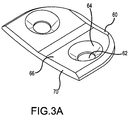
FIG. 3A illustrates a mounting bracket for a rotor retention device, in accordance with various embodiments; -
FIG. 3B illustrates mounting brackets coupled to wings of a rotor retention device, in accordance with various embodiments; -
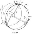
FIG. 4A illustrates a rotor retention device fastened to a diffuser, in accordance with various embodiments; -
FIG. 4B illustrates a cross sectional view of a mounting bracket fastened to a diffuser, in accordance with various embodiments; -
FIG. 4C illustrates a mounting bracket mounted to a diffuser case, in accordance with various embodiments; -
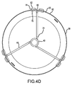
FIG. 4D illustrates a retention device mounted to a diffuser and viewed from aft to forward, in accordance with various embodiments; -
FIG. 5A illustrates an exemplary diffuser of a radial turbine engine, in accordance with various embodiments; -
FIG. 5B illustrates openings machined into a diffuser, in accordance with various embodiments; -
FIG. 5C illustrates a perspective view of a diffuser with a retention device mounted to the diffuser, in accordance with various embodiments; -
FIG. 5D illustrates a cylindrical diffuser with a retention device mounted central to the diffuser from aft looking forward, in accordance with various embodiments; and -
FIG. 5E illustrates exemplary hardware used to fasten a retention device to a diffuser, in accordance with various embodiments. - The detailed description of exemplary embodiments herein makes reference to the accompanying drawings, which show exemplary embodiments by way of illustration. While these exemplary embodiments are described in sufficient detail to enable those skilled in the art to practice the exemplary embodiments of the disclosure, it should be understood that other embodiments may be realized and that logical changes and adaptations in design and construction may be made in accordance with this disclosure and the teachings herein. Thus, the detailed description herein is presented for purposes of illustration only and not limitation. For example, the steps recited in any of the method or process descriptions may be executed in any order and are not necessarily limited to the order presented.
- Furthermore, any reference to singular includes plural embodiments, and any reference to more than one component or step may include a singular embodiment or step. Also, any reference to attached, fixed, connected or the like may include permanent, removable, temporary, partial, full and/or any other possible attachment option. Additionally, any reference to without contact (or similar phrases) may also include reduced contact or minimal contact. Surface shading lines may be used throughout the figures to denote different parts but not necessarily to denote the same or different materials.
- As used herein, "aft" refers to the direction associated with the tail (e.g., the back end) of an aircraft, or generally, to the direction of exhaust of the gas turbine. As used herein, "forward" refers to the direction associated with the nose (e.g., the front end) of an aircraft, or generally, to the direction of flight or motion.
- As used herein, "distal" refers to the direction radially outward, or generally, away from the axis of rotation of a turbine engine. As used herein, "proximal" refers to a direction radially inward, or generally, towards the axis of rotation of a turbine engine.
- With reference to
FIG. 1 , aradial turbine engine 10 comprising aretention device 24 is shown, in accordance with various embodiments.Radial turbine engine 10 may comprise afan 12 through which ambient air is propelled and acentrifugal compressor 14 for pressurizing the air. Acombustor 16 may be disposed aft of centrifugal compressor 14 (also referred to herein as an impeller). The compressed air is mixed with fuel and ignited in the combustor, generating an annular stream of hot combustion gases. Aturbine 18 is aft of thecombustor 16 and is also mechanically coupled tocentrifugal compressor 14 throughshaft 19.Turbine 18 extracts energy from the combustedgases exiting combustor 16. In various embodiments, one or more of the previous components, such asfan 12, may not be present.Retention device 24 may be disposed aft ofturbine 18 and in the exhaust path of the engine. The clearance C between thehub 23 ofrotor 21 andcenter bullet 40 ofretention device 24 may be approximately 0.080 inches to 0.12 inches (0.2 cm to 0.3 cm) to retain a lose turbine wheel. In that regard, the axial travel distance of a turbine wheel may be limited and the turbine wheel retained in substantially the same position (i.e., the distance a turbine wheel may shift is limited by the clearance distance). - Various components of
radial turbine engine 10 may rotate about axis ofrotation 11. Thecentrifugal compressor 14 may comprisecentrifugal impeller 20 which directs the pressurized air intodiffuser vanes 22. The forward and aft positions ofradial turbine engine 10 may be described relatively along axis ofrotation 11. For example,fan 12 may be referred to as forward ofturbine 18 andturbine 18 may be referred to as aft offan 12. As air flows fromfan 12 to the more aft components ofradial turbine engine 10, axis ofrotation 11 may also generally define the net direction of the air stream flow. However, the direction of the air stream flow may vary through the individual components. For example, the air flow may be radial in an exducer section ofcentrifugal impeller 20. The present disclosure is applicable to other types of turbine engines, such as auxiliary power units, turbo-shaft units, turbojet units, and turbo-prop units. - With reference to
FIGs. 2A and2B , acenter bullet 40 andwings 44 of aretention device 24 is shown, in accordance with various embodiments. Thecenter bullet 40 is hollow withcenter bullet 40 defininginternal cavity 42 to reduce the weight of the center bullet.Center bullet 40 may be made from a solid piece of metal (i.e., bar stock) and bored out, orcenter bullet 40 may be made from a hollow metal tube. Acap 46 may be formed integral withcenter bullet 40 or may be welded on tocenter bullet 40.Cap 46 may provide a solid surface to prevent exhaust from flowing throughcenter bullet 40.Center bullet 40 may have a cylindrical shape with a diameter ofcenter bullet 40 selected relative to a diameter of an adjacent wheel hub. For example,center bullet 40 may have a diameter in the range of 80% to 120% of the diameter of an adjacent turbine wheel hub. In that regard,cap 46 andcenter bullet 40 may minimize a distance in the aft direction that a loose turbine wheel may travel. - In various embodiments, the lengths of
wings 44 may be substantially equal, with the wings circumferentially spaced apart from one another. The wings may be spaced at unequal distances aboutcenter bullet 40, but equal distances betweenwings 44 may tend to distribute the load onretention device 24 more evenly than unequal distances. Three or more wings may provide accurate locating of thecenter bullet 40 in a configuration that tends to reduce blockage for exhaust flow and tends to reduce weight.Wings 44 may comprise amating surface 48 at a distal end from the cylindrical body ofcenter bullet 40.Wings 44 may be coupled tocenter bullet 40 by welding or other suitable metal joining technique, orwings 44 may be formed integrally withcenter bullet 40. The shape ofwings 44 may be selected to minimize vibrations. For example,wings 44 may be shaped so thatretention device 24 does not have resonant frequencies near the operating frequencies of the engine. As illustrated,wings 44 may have a triangular shape with the joint atcenter bullet 40 have a longer axial length thanmating surface 48 to limit vibration during use. - In various embodiments, the wings may meet the bullet at a substantially tangential angle (i.e.,
wings 44 may lie on a non-radial plane with respect to the cylindrical body of center bullet 40). Ifcenter bullet 40 is welded towings 44, the wings may be at an angle fromcenter bullet 40 that is non-radial to provide a strong joint betweenwings 44 andcenter bullet 40. The plane ofwings 44 may be at an angle relative to the axis ofrotation 11 of radial turbine engine 10 (ofFIG. 1 ). In that regard,wings 44 may have a minimal impact on the sound signature of the engine. The angle of the wings may be selected to minimize the difference between the flow angle of air in an exhaust of turbine 18 (ofFIG. 1 ), which may be spinning as it reacheswings 44 ofretention device 24. - With reference to
FIGs. 3A and3B , a mountingbracket 60 is shown coupled towings 44, in accordance with various embodiments. Mountingbracket 60 may comprise one ormore openings 62. Mountingbracket 60 may be a pad with countersunk sidewalls 64 ofopenings 62 shaped to match a contour of a later-installed fastener. Countersunk sidewalls 64 may reduce and/or eliminate the protrusion of a fastener used in conjunction with mountingbracket 60.Inner surface 66 of mountingbracket 60 may be configured to weld towings 44. Anaft surface 70 of mountingbracket 60 may face in an aft direction in response to mountingbracket 60 being welded or otherwise coupled towing 44.Wing 44 may be coupled toinner surface 66 whileouter surface 68 faces away fromwing 44 when mounted. A forward edge of mounting bracket may be angled or otherwise aerodynamically shaped to reduce drag on exhaust gases. Mountingbracket 60 may be made from, for example, an austenitic nickel-chromium-based alloy or other materials capable of withstanding exhaust temperatures. - With reference to
FIGs. 4A through 4D ,retention device 24 is shown mounted to a diffuser and/or to piece of sheet metal. Mountingbrackets 60 may be mounted todiffuser 80 by fasteners such as rivets or bolts. In that regard, fasteners may extend through openings machined throughdiffuser 80. For example,rivet head 86 may rest in mountingbracket 60 and extend through mountingbracket 60,diffuser 80,spacer 84, and to atail end 82 of the rivet. Anaft surface 70 of mountingbracket 60 may be flush withaft surface 83 ofdiffuser 80 ordiffuser 80 mayoverhang mounting bracket 60. - In various embodiments, aft
surface 83 ofdiffuser 80 may extend further aft than mountingbracket 60 or mountingbracket 60 may be flush withaft surface 83. As illustrated inFIG. 4D ,wings 44 may be tangentially orientated relative to centerbullet 40. Similarly, the spacing ofwings 44 circumferentially aboutcenter bullet 40 may be substantially equal.Wings 44 may each comprise the same length to locatecenter bullet 40 centrally to the cylindrical walls ofdiffuser 80.Internal surface 88 may face radially inward towardswings 44 andbullet 40, andouter surface 90 may face radially outward. - In various embodiments,
center bullet 40 andwings 44 may be formed as an integral unit using additive manufacturing techniques. For example,center bullet 40 andwings 44 may be formed by at least one of direct metal laser sintering, selective laser sintering, selective laser melting, electron-beam melting, or electron-beam freeform fabrication. Forming the components ofretention device 24 may also include the steps of forming a core of the component wall using additive manufacturing or other techniques and casting the component. A mold may be formed as one piece with the core using additive manufacturing.Center bullet 40 andwings 44 may also be formed using a machining process. For example, a wrought piece of metal may be turned to formcenter bullet 40 and/orwings 44. Additive manufacturing and/or machining wrought metals may yield higher strength, lighter weight components than casting. In various embodiments,center bullet 40, andwing 44 may be made from, for example, an austenitic nickel-chromium-based alloy, or other materials capable of withstanding exhaust temperatures. - With reference to
FIGs. 5A through 5E , a method of mounting a retention device in a radial turbine engine is shown, in accordance with various embodiments. InFIG. 5A , a detailed view ofdiffuser 80 is shown, according to various embodiments.Diffuser 80 is positioned aft of, and radially outward from,rotor 21 as illustrated inFIG. 1 .Diffuser 80 may guide an exhaust stream exiting a turbine out of the engine. With reference toFIG. 5B , fastener holes 100 are formed throughdiffuser 80. Fastener holes 100 may be formed using a drill and a drill fixture to align drill openings with respect to one another. The drill fixture may also include a clocking mechanism to alignfastener holes 100 relative to other features situated nearby ondiffuser 80. Fastener openings may be drilled frominternal surface 88 orouter surface 90 ofdiffuser 80. Fastener holes 100 may be formed throughdiffuser 80 whilediffuser 80 is mounted on an aircraft. In that regard, retention device 24 (ofFIG. 5D ) may be mounted todiffuser 80 on an aircraft in the field through the use of fasteners.Retention device 24 mounted todiffuser 80 on-wing may enable efficient retrofitting on existing radial turbine engines. - With reference to
FIGs. 5C-5E ,retention device 24 is shown mounted todiffuser 80. Fasteners (such as the rivets ofFIG. 4B or bolts ofFIG. 5E ) may be used to secureretention device 24 todiffuser 80.Bolts 102 may be inserted through mountingbracket 60 and fastener holes 100 (ofFIG. 5B ) ofdiffuser 80 to secureretention device 24 withindiffuser 80.Bolt 102 may have a head resting at least partially within mountingbracket 60 with a threaded portion extending throughdiffuser 80.Bolt 102 may be made from a high-performance nickel alloy.Bolt 102 may further be silver plated to provide lubrication and corrosion deterrence. Aspacer 106 may rest betweendiffuser 80 andnut 104.Spacer 106 andnut 104 may also be made from a high-performance nickel alloy.Nut 104 may be tightened on diffuser so that any excess threaded portion ofbolt 102 extends radially outward fromdiffuser 80.Wing 44 may meet mountingbracket 60 at a location central to fastener holes 100 (ofFIG. 5B ) to accommodate installation ofbolts 102. - Benefits and other advantages have been described herein with regard to specific embodiments. Furthermore, the connecting lines shown in the various figures contained herein are intended to represent exemplary functional relationships and/or physical couplings between the various elements. It should be noted that many alternative or additional functional relationships or physical connections may be present in a practical system. However, the benefits, advantages, and any elements that may cause any benefit or advantage to occur or become more pronounced are not to be construed as critical, required, or essential features or elements of the disclosure. The scope of the disclosure is accordingly to be limited by nothing other than the appended claims, in which reference to an element in the singular is not intended to mean "one and only one" unless explicitly so stated, but rather "one or more." Moreover, where a phrase similar to "at least one of A, B, or C" is used in the claims, it is intended that the phrase be interpreted to mean that A alone may be present in an embodiment, B alone may be present in an embodiment, C alone may be present in an embodiment, or that any combination of the elements A, B and C may be present in a single embodiment; for example, A and B, A and C, B and C, or A and B and C.
- Systems, methods and apparatus are provided herein. In the detailed description herein, references to "various embodiments", "one embodiment", "an embodiment", "an example embodiment", etc., indicate that the embodiment described may include a particular feature, structure, or characteristic, but every embodiment may not necessarily include the particular feature, structure, or characteristic. Moreover, such phrases are not necessarily referring to the same embodiment. Further, when a particular feature, structure, or characteristic is described in connection with an embodiment, it is submitted that it is within the knowledge of one skilled in the art to affect such feature, structure, or characteristic in connection with other embodiments whether or not explicitly described. After reading the description, it will be apparent to one skilled in the relevant art(s) how to implement the disclosure in alternative embodiments.
Claims (15)
- A method of making a turbine retention device (24), comprising:forming a bullet (40) having a cylindrical geometry;forming a wing (44);coupling the wing (44) to the bullet (40) with a proximal portion of the wing (44) along an axial length of the bullet (40); andcoupling a mounting bracket (60) to a distal end of the wing (44).
- The method of claim 1, further comprising spacing a plurality of wings (44) including the wing (44) equally around the bullet (40).
- The method of claim 2, further comprising welding the wings (44) to a plurality of mounting brackets (60) including the mounting bracket (60).
- The method of claim 2 or 3, further comprising welding the wings (44) to the bullet (40).
- The method of claim 2, 3 or 4, wherein the coupling the wings (44) to the bullet (40) further comprises coupling the wings (44) at a tangential angle to the bullet (40).
- A method of making a turbine retention device (24), comprising:forming a bullet (40) with wings (44) extending away from a cylindrical body of the bullet (40) at a substantially tangential angle; andcoupling mounting brackets (60) to the wings (44).
- The method of any preceding claim, further comprising boring the bullet (40).
- The method of any preceding claim, further comprising forming the bullet (40) additively.
- The method of any preceding claim, further comprising forming the wing(s) (44) additively.
- The method of any of claims 1 to 7, further comprising forming the wing(s) (44) and/or the bullet (40) by machining a wrought metal.
- The method of any preceding claim, wherein the forming the bullet (40) with the wing(s) (44) further comprises forming the bullet (40) integrally with the wing(s) (44).
- A turbine retention device (24), comprising:a bullet (40) having a cylindrical body;wings (44) disposed circumferentially about the bullet (40); andmounting brackets (60) coupled to the wings (44).
- The turbine retention device of claim 12, wherein the wings (44) meet the bullet (40) at a substantially tangential angle.
- The turbine retention device of claim 12 or 13, wherein the bullet (40), the wings (44), and the mounting brackets (60) are made from one or more nickel superalloy.
- The turbine retention device of claim 12, 13 or 14, wherein the bullet (40) has a hollow and cylindrical geometry.
Applications Claiming Priority (1)
| Application Number | Priority Date | Filing Date | Title |
|---|---|---|---|
| US14/618,689 US10072524B2 (en) | 2015-02-10 | 2015-02-10 | Method of making a turbine wheel axial retention device |
Publications (2)
| Publication Number | Publication Date |
|---|---|
| EP3056681A1 true EP3056681A1 (en) | 2016-08-17 |
| EP3056681B1 EP3056681B1 (en) | 2017-11-15 |
Family
ID=55353049
Family Applications (1)
| Application Number | Title | Priority Date | Filing Date |
|---|---|---|---|
| EP16154909.2A Active EP3056681B1 (en) | 2015-02-10 | 2016-02-09 | Method of making a turbine wheel axial retention device |
Country Status (2)
| Country | Link |
|---|---|
| US (1) | US10072524B2 (en) |
| EP (1) | EP3056681B1 (en) |
Families Citing this family (6)
| Publication number | Priority date | Publication date | Assignee | Title |
|---|---|---|---|---|
| US10550726B2 (en) | 2017-01-30 | 2020-02-04 | General Electric Company | Turbine spider frame with additive core |
| US10654577B2 (en) | 2017-02-22 | 2020-05-19 | General Electric Company | Rainbow flowpath low pressure turbine rotor assembly |
| US11421627B2 (en) | 2017-02-22 | 2022-08-23 | General Electric Company | Aircraft and direct drive engine under wing installation |
| RU2678187C2 (en) * | 2017-06-16 | 2019-01-24 | Публичное акционерное общество "ОДК-Уфимское моторостроительное производственное объединение" (ПАО "ОДК-УМПО") | Mounting bracket of unit on shell of turbomachine body |
| US10774685B2 (en) * | 2018-04-30 | 2020-09-15 | Ratheon Technologies Corporation | Gas turbine engine exhaust component |
| US11428160B2 (en) | 2020-12-31 | 2022-08-30 | General Electric Company | Gas turbine engine with interdigitated turbine and gear assembly |
Citations (6)
| Publication number | Priority date | Publication date | Assignee | Title |
|---|---|---|---|---|
| US2938336A (en) * | 1956-12-06 | 1960-05-31 | United Aircraft Corp | Gas flow straightening vanes |
| EP2003293A1 (en) * | 2007-06-13 | 2008-12-17 | Snecma | Turbomachine exhaust case |
| WO2010007220A2 (en) * | 2008-06-25 | 2010-01-21 | Snecma | Turbomachine structural casing |
| US20100221115A1 (en) * | 2009-02-27 | 2010-09-02 | Honeywell International Inc. | Retention structures and exit guide vane assemblies |
| US20140003911A1 (en) * | 2012-06-27 | 2014-01-02 | Hamilton Sundstrand Corporation | Turbine wheel catcher |
| US20140165590A1 (en) * | 2012-12-13 | 2014-06-19 | Hamilton Sundstrand Corporation | Turbine hub retainer |
Family Cites Families (7)
| Publication number | Priority date | Publication date | Assignee | Title |
|---|---|---|---|---|
| GB2275308B (en) * | 1993-02-20 | 1997-02-26 | Rolls Royce Plc | A mounting for coupling a turbofan gas turbine engine to an aircraft structure |
| US6324831B1 (en) * | 2000-01-25 | 2001-12-04 | Hamilton Sundstrand Corporation | Monorotor for a gas turbine engine |
| US8181555B2 (en) * | 2007-04-03 | 2012-05-22 | Climax Portable Machine Tools, Inc. | Machine for boring, turning, and face grooving |
| US20090068016A1 (en) * | 2007-04-20 | 2009-03-12 | Honeywell International, Inc. | Shrouded single crystal dual alloy turbine disk |
| FR2997996B1 (en) * | 2012-11-12 | 2015-01-09 | Snecma | AIR TUBE SUPPORT SUPPORT IN A TURBOMACHINE |
| US9664067B2 (en) * | 2014-10-10 | 2017-05-30 | General Electric Company | Seal retaining assembly |
| US9757936B2 (en) * | 2014-12-29 | 2017-09-12 | General Electric Company | Hot gas path component |
-
2015
- 2015-02-10 US US14/618,689 patent/US10072524B2/en active Active
-
2016
- 2016-02-09 EP EP16154909.2A patent/EP3056681B1/en active Active
Patent Citations (6)
| Publication number | Priority date | Publication date | Assignee | Title |
|---|---|---|---|---|
| US2938336A (en) * | 1956-12-06 | 1960-05-31 | United Aircraft Corp | Gas flow straightening vanes |
| EP2003293A1 (en) * | 2007-06-13 | 2008-12-17 | Snecma | Turbomachine exhaust case |
| WO2010007220A2 (en) * | 2008-06-25 | 2010-01-21 | Snecma | Turbomachine structural casing |
| US20100221115A1 (en) * | 2009-02-27 | 2010-09-02 | Honeywell International Inc. | Retention structures and exit guide vane assemblies |
| US20140003911A1 (en) * | 2012-06-27 | 2014-01-02 | Hamilton Sundstrand Corporation | Turbine wheel catcher |
| US20140165590A1 (en) * | 2012-12-13 | 2014-06-19 | Hamilton Sundstrand Corporation | Turbine hub retainer |
Also Published As
| Publication number | Publication date |
|---|---|
| US10072524B2 (en) | 2018-09-11 |
| US20160230604A1 (en) | 2016-08-11 |
| EP3056681B1 (en) | 2017-11-15 |
Similar Documents
| Publication | Publication Date | Title |
|---|---|---|
| EP3056681B1 (en) | Method of making a turbine wheel axial retention device | |
| EP2857657B1 (en) | Gas turbine engine inlet assembly and method of making the same | |
| EP3632683B1 (en) | Gas turbine engine with a unitary structure and method for manufacturing the same | |
| EP2346736B1 (en) | Integrated inlet design | |
| US9803498B2 (en) | One-piece fuel nozzle for a thrust engine | |
| JP6131010B2 (en) | Metal fan blade platform | |
| EP2472059B1 (en) | Vane with spar mounted composite airfoil | |
| EP2867492B1 (en) | Turbine wheel catcher | |
| CN109415940A (en) | Metal leading edge for composite fan blade | |
| JP2007500298A (en) | Turbofan case and manufacturing method | |
| EP2589759B1 (en) | Mid-Turbine Bearing Support | |
| US10443447B2 (en) | Doubler attachment system | |
| CN110778370B (en) | Nacelle inlet lip fuse structure | |
| EP2932069B1 (en) | Turbine hub retainer | |
| US20120020771A1 (en) | One-piece compressor and turbine containment system | |
| US10982852B2 (en) | Cowl integration to combustor wall | |
| EP2980393B1 (en) | Gas turbine engine | |
| EP3617453B1 (en) | Fan blade having closed metal sheath | |
| US10018057B2 (en) | Method of mounting a turbine wheel axial retention device | |
| US10371162B2 (en) | Integrally bladed fan rotor | |
| US9435215B2 (en) | Gas turbine structure |
Legal Events
| Date | Code | Title | Description |
|---|---|---|---|
| PUAI | Public reference made under article 153(3) epc to a published international application that has entered the european phase |
Free format text: ORIGINAL CODE: 0009012 |
|
| AK | Designated contracting states |
Kind code of ref document: A1 Designated state(s): AL AT BE BG CH CY CZ DE DK EE ES FI FR GB GR HR HU IE IS IT LI LT LU LV MC MK MT NL NO PL PT RO RS SE SI SK SM TR |
|
| AX | Request for extension of the european patent |
Extension state: BA ME |
|
| RAP1 | Party data changed (applicant data changed or rights of an application transferred) |
Owner name: UNITED TECHNOLOGIES CORPORATION |
|
| STAA | Information on the status of an ep patent application or granted ep patent |
Free format text: STATUS: REQUEST FOR EXAMINATION WAS MADE |
|
| 17P | Request for examination filed |
Effective date: 20170217 |
|
| RBV | Designated contracting states (corrected) |
Designated state(s): AL AT BE BG CH CY CZ DE DK EE ES FI FR GB GR HR HU IE IS IT LI LT LU LV MC MK MT NL NO PL PT RO RS SE SI SK SM TR |
|
| RIC1 | Information provided on ipc code assigned before grant |
Ipc: F01D 25/24 20060101ALI20170331BHEP Ipc: F01D 9/04 20060101AFI20170331BHEP |
|
| GRAP | Despatch of communication of intention to grant a patent |
Free format text: ORIGINAL CODE: EPIDOSNIGR1 |
|
| STAA | Information on the status of an ep patent application or granted ep patent |
Free format text: STATUS: GRANT OF PATENT IS INTENDED |
|
| RIC1 | Information provided on ipc code assigned before grant |
Ipc: F01D 9/04 20060101AFI20170509BHEP |
|
| INTG | Intention to grant announced |
Effective date: 20170531 |
|
| GRAS | Grant fee paid |
Free format text: ORIGINAL CODE: EPIDOSNIGR3 |
|
| GRAA | (expected) grant |
Free format text: ORIGINAL CODE: 0009210 |
|
| STAA | Information on the status of an ep patent application or granted ep patent |
Free format text: STATUS: THE PATENT HAS BEEN GRANTED |
|
| AK | Designated contracting states |
Kind code of ref document: B1 Designated state(s): AL AT BE BG CH CY CZ DE DK EE ES FI FR GB GR HR HU IE IS IT LI LT LU LV MC MK MT NL NO PL PT RO RS SE SI SK SM TR |
|
| REG | Reference to a national code |
Ref country code: CH Ref legal event code: EP Ref country code: GB Ref legal event code: FG4D Ref country code: AT Ref legal event code: REF Ref document number: 946503 Country of ref document: AT Kind code of ref document: T Effective date: 20171115 |
|
| REG | Reference to a national code |
Ref country code: IE Ref legal event code: FG4D |
|
| REG | Reference to a national code |
Ref country code: DE Ref legal event code: R096 Ref document number: 602016000776 Country of ref document: DE |
|
| REG | Reference to a national code |
Ref country code: FR Ref legal event code: PLFP Year of fee payment: 3 |
|
| REG | Reference to a national code |
Ref country code: NL Ref legal event code: MP Effective date: 20171115 |
|
| REG | Reference to a national code |
Ref country code: LT Ref legal event code: MG4D |
|
| REG | Reference to a national code |
Ref country code: AT Ref legal event code: MK05 Ref document number: 946503 Country of ref document: AT Kind code of ref document: T Effective date: 20171115 |
|
| PG25 | Lapsed in a contracting state [announced via postgrant information from national office to epo] |
Ref country code: LT Free format text: LAPSE BECAUSE OF FAILURE TO SUBMIT A TRANSLATION OF THE DESCRIPTION OR TO PAY THE FEE WITHIN THE PRESCRIBED TIME-LIMIT Effective date: 20171115 Ref country code: NL Free format text: LAPSE BECAUSE OF FAILURE TO SUBMIT A TRANSLATION OF THE DESCRIPTION OR TO PAY THE FEE WITHIN THE PRESCRIBED TIME-LIMIT Effective date: 20171115 Ref country code: FI Free format text: LAPSE BECAUSE OF FAILURE TO SUBMIT A TRANSLATION OF THE DESCRIPTION OR TO PAY THE FEE WITHIN THE PRESCRIBED TIME-LIMIT Effective date: 20171115 Ref country code: ES Free format text: LAPSE BECAUSE OF FAILURE TO SUBMIT A TRANSLATION OF THE DESCRIPTION OR TO PAY THE FEE WITHIN THE PRESCRIBED TIME-LIMIT Effective date: 20171115 Ref country code: SE Free format text: LAPSE BECAUSE OF FAILURE TO SUBMIT A TRANSLATION OF THE DESCRIPTION OR TO PAY THE FEE WITHIN THE PRESCRIBED TIME-LIMIT Effective date: 20171115 Ref country code: NO Free format text: LAPSE BECAUSE OF FAILURE TO SUBMIT A TRANSLATION OF THE DESCRIPTION OR TO PAY THE FEE WITHIN THE PRESCRIBED TIME-LIMIT Effective date: 20180215 |
|
| PG25 | Lapsed in a contracting state [announced via postgrant information from national office to epo] |
Ref country code: GR Free format text: LAPSE BECAUSE OF FAILURE TO SUBMIT A TRANSLATION OF THE DESCRIPTION OR TO PAY THE FEE WITHIN THE PRESCRIBED TIME-LIMIT Effective date: 20180216 Ref country code: AT Free format text: LAPSE BECAUSE OF FAILURE TO SUBMIT A TRANSLATION OF THE DESCRIPTION OR TO PAY THE FEE WITHIN THE PRESCRIBED TIME-LIMIT Effective date: 20171115 Ref country code: LV Free format text: LAPSE BECAUSE OF FAILURE TO SUBMIT A TRANSLATION OF THE DESCRIPTION OR TO PAY THE FEE WITHIN THE PRESCRIBED TIME-LIMIT Effective date: 20171115 Ref country code: RS Free format text: LAPSE BECAUSE OF FAILURE TO SUBMIT A TRANSLATION OF THE DESCRIPTION OR TO PAY THE FEE WITHIN THE PRESCRIBED TIME-LIMIT Effective date: 20171115 Ref country code: BG Free format text: LAPSE BECAUSE OF FAILURE TO SUBMIT A TRANSLATION OF THE DESCRIPTION OR TO PAY THE FEE WITHIN THE PRESCRIBED TIME-LIMIT Effective date: 20180215 Ref country code: HR Free format text: LAPSE BECAUSE OF FAILURE TO SUBMIT A TRANSLATION OF THE DESCRIPTION OR TO PAY THE FEE WITHIN THE PRESCRIBED TIME-LIMIT Effective date: 20171115 |
|
| PG25 | Lapsed in a contracting state [announced via postgrant information from national office to epo] |
Ref country code: EE Free format text: LAPSE BECAUSE OF FAILURE TO SUBMIT A TRANSLATION OF THE DESCRIPTION OR TO PAY THE FEE WITHIN THE PRESCRIBED TIME-LIMIT Effective date: 20171115 Ref country code: CY Free format text: LAPSE BECAUSE OF FAILURE TO SUBMIT A TRANSLATION OF THE DESCRIPTION OR TO PAY THE FEE WITHIN THE PRESCRIBED TIME-LIMIT Effective date: 20171115 Ref country code: DK Free format text: LAPSE BECAUSE OF FAILURE TO SUBMIT A TRANSLATION OF THE DESCRIPTION OR TO PAY THE FEE WITHIN THE PRESCRIBED TIME-LIMIT Effective date: 20171115 Ref country code: CZ Free format text: LAPSE BECAUSE OF FAILURE TO SUBMIT A TRANSLATION OF THE DESCRIPTION OR TO PAY THE FEE WITHIN THE PRESCRIBED TIME-LIMIT Effective date: 20171115 Ref country code: SK Free format text: LAPSE BECAUSE OF FAILURE TO SUBMIT A TRANSLATION OF THE DESCRIPTION OR TO PAY THE FEE WITHIN THE PRESCRIBED TIME-LIMIT Effective date: 20171115 |
|
| REG | Reference to a national code |
Ref country code: DE Ref legal event code: R097 Ref document number: 602016000776 Country of ref document: DE |
|
| PG25 | Lapsed in a contracting state [announced via postgrant information from national office to epo] |
Ref country code: PL Free format text: LAPSE BECAUSE OF FAILURE TO SUBMIT A TRANSLATION OF THE DESCRIPTION OR TO PAY THE FEE WITHIN THE PRESCRIBED TIME-LIMIT Effective date: 20171115 Ref country code: SM Free format text: LAPSE BECAUSE OF FAILURE TO SUBMIT A TRANSLATION OF THE DESCRIPTION OR TO PAY THE FEE WITHIN THE PRESCRIBED TIME-LIMIT Effective date: 20171115 Ref country code: RO Free format text: LAPSE BECAUSE OF FAILURE TO SUBMIT A TRANSLATION OF THE DESCRIPTION OR TO PAY THE FEE WITHIN THE PRESCRIBED TIME-LIMIT Effective date: 20171115 Ref country code: IT Free format text: LAPSE BECAUSE OF FAILURE TO SUBMIT A TRANSLATION OF THE DESCRIPTION OR TO PAY THE FEE WITHIN THE PRESCRIBED TIME-LIMIT Effective date: 20171115 |
|
| PLBE | No opposition filed within time limit |
Free format text: ORIGINAL CODE: 0009261 |
|
| STAA | Information on the status of an ep patent application or granted ep patent |
Free format text: STATUS: NO OPPOSITION FILED WITHIN TIME LIMIT |
|
| PG25 | Lapsed in a contracting state [announced via postgrant information from national office to epo] |
Ref country code: MC Free format text: LAPSE BECAUSE OF FAILURE TO SUBMIT A TRANSLATION OF THE DESCRIPTION OR TO PAY THE FEE WITHIN THE PRESCRIBED TIME-LIMIT Effective date: 20171115 |
|
| 26N | No opposition filed |
Effective date: 20180817 |
|
| REG | Reference to a national code |
Ref country code: IE Ref legal event code: MM4A |
|
| REG | Reference to a national code |
Ref country code: BE Ref legal event code: MM Effective date: 20180228 |
|
| PG25 | Lapsed in a contracting state [announced via postgrant information from national office to epo] |
Ref country code: LU Free format text: LAPSE BECAUSE OF NON-PAYMENT OF DUE FEES Effective date: 20180209 Ref country code: SI Free format text: LAPSE BECAUSE OF FAILURE TO SUBMIT A TRANSLATION OF THE DESCRIPTION OR TO PAY THE FEE WITHIN THE PRESCRIBED TIME-LIMIT Effective date: 20171115 |
|
| PG25 | Lapsed in a contracting state [announced via postgrant information from national office to epo] |
Ref country code: IE Free format text: LAPSE BECAUSE OF NON-PAYMENT OF DUE FEES Effective date: 20180209 |
|
| PG25 | Lapsed in a contracting state [announced via postgrant information from national office to epo] |
Ref country code: BE Free format text: LAPSE BECAUSE OF NON-PAYMENT OF DUE FEES Effective date: 20180228 |
|
| REG | Reference to a national code |
Ref country code: CH Ref legal event code: PL |
|
| PG25 | Lapsed in a contracting state [announced via postgrant information from national office to epo] |
Ref country code: LI Free format text: LAPSE BECAUSE OF NON-PAYMENT OF DUE FEES Effective date: 20190228 Ref country code: CH Free format text: LAPSE BECAUSE OF NON-PAYMENT OF DUE FEES Effective date: 20190228 |
|
| PG25 | Lapsed in a contracting state [announced via postgrant information from national office to epo] |
Ref country code: MT Free format text: LAPSE BECAUSE OF NON-PAYMENT OF DUE FEES Effective date: 20180209 |
|
| PG25 | Lapsed in a contracting state [announced via postgrant information from national office to epo] |
Ref country code: TR Free format text: LAPSE BECAUSE OF FAILURE TO SUBMIT A TRANSLATION OF THE DESCRIPTION OR TO PAY THE FEE WITHIN THE PRESCRIBED TIME-LIMIT Effective date: 20171115 |
|
| PG25 | Lapsed in a contracting state [announced via postgrant information from national office to epo] |
Ref country code: PT Free format text: LAPSE BECAUSE OF FAILURE TO SUBMIT A TRANSLATION OF THE DESCRIPTION OR TO PAY THE FEE WITHIN THE PRESCRIBED TIME-LIMIT Effective date: 20171115 |
|
| PG25 | Lapsed in a contracting state [announced via postgrant information from national office to epo] |
Ref country code: HU Free format text: LAPSE BECAUSE OF FAILURE TO SUBMIT A TRANSLATION OF THE DESCRIPTION OR TO PAY THE FEE WITHIN THE PRESCRIBED TIME-LIMIT; INVALID AB INITIO Effective date: 20160209 Ref country code: MK Free format text: LAPSE BECAUSE OF NON-PAYMENT OF DUE FEES Effective date: 20171115 |
|
| PG25 | Lapsed in a contracting state [announced via postgrant information from national office to epo] |
Ref country code: AL Free format text: LAPSE BECAUSE OF FAILURE TO SUBMIT A TRANSLATION OF THE DESCRIPTION OR TO PAY THE FEE WITHIN THE PRESCRIBED TIME-LIMIT Effective date: 20171115 Ref country code: IS Free format text: LAPSE BECAUSE OF FAILURE TO SUBMIT A TRANSLATION OF THE DESCRIPTION OR TO PAY THE FEE WITHIN THE PRESCRIBED TIME-LIMIT Effective date: 20180315 |
|
| REG | Reference to a national code |
Ref country code: DE Ref legal event code: R081 Ref document number: 602016000776 Country of ref document: DE Owner name: RAYTHEON TECHNOLOGIES CORPORATION (N.D.GES.D.S, US Free format text: FORMER OWNER: UNITED TECHNOLOGIES CORPORATION, FARMINGTON, CONN., US Ref country code: DE Ref legal event code: R081 Ref document number: 602016000776 Country of ref document: DE Owner name: RTX CORPORATION (N.D.GES.D. STAATES DELAWARE),, US Free format text: FORMER OWNER: UNITED TECHNOLOGIES CORPORATION, FARMINGTON, CONN., US |
|
| P01 | Opt-out of the competence of the unified patent court (upc) registered |
Effective date: 20230520 |
|
| REG | Reference to a national code |
Ref country code: DE Ref legal event code: R081 Ref document number: 602016000776 Country of ref document: DE Owner name: RTX CORPORATION (N.D.GES.D. STAATES DELAWARE),, US Free format text: FORMER OWNER: RAYTHEON TECHNOLOGIES CORPORATION (N.D.GES.D.STAATES DELAWARE), ARLINGTON, VA, US |
|
| PGFP | Annual fee paid to national office [announced via postgrant information from national office to epo] |
Ref country code: GB Payment date: 20260121 Year of fee payment: 11 |
|
| PGFP | Annual fee paid to national office [announced via postgrant information from national office to epo] |
Ref country code: DE Payment date: 20260121 Year of fee payment: 11 |
|
| PGFP | Annual fee paid to national office [announced via postgrant information from national office to epo] |
Ref country code: FR Payment date: 20260121 Year of fee payment: 11 |