EP3056605B1 - Sheet manufacturing apparatus - Google Patents
Sheet manufacturing apparatus Download PDFInfo
- Publication number
- EP3056605B1 EP3056605B1 EP16153673.5A EP16153673A EP3056605B1 EP 3056605 B1 EP3056605 B1 EP 3056605B1 EP 16153673 A EP16153673 A EP 16153673A EP 3056605 B1 EP3056605 B1 EP 3056605B1
- Authority
- EP
- European Patent Office
- Prior art keywords
- tank
- unit
- additive agent
- manufacturing apparatus
- sheet manufacturing
- Prior art date
- Legal status (The legal status is an assumption and is not a legal conclusion. Google has not performed a legal analysis and makes no representation as to the accuracy of the status listed.)
- Active
Links
- 238000004519 manufacturing process Methods 0.000 title claims description 59
- 239000003795 chemical substances by application Substances 0.000 claims description 127
- 239000000654 additive Substances 0.000 claims description 126
- 230000000996 additive effect Effects 0.000 claims description 125
- 238000001514 detection method Methods 0.000 claims description 86
- 239000000463 material Substances 0.000 claims description 48
- 239000000835 fiber Substances 0.000 claims description 45
- 238000010438 heat treatment Methods 0.000 claims description 14
- 238000000034 method Methods 0.000 description 25
- 239000000123 paper Substances 0.000 description 19
- 238000012216 screening Methods 0.000 description 18
- 229920005989 resin Polymers 0.000 description 17
- 239000011347 resin Substances 0.000 description 17
- 238000005520 cutting process Methods 0.000 description 15
- 239000000976 ink Substances 0.000 description 15
- 239000002245 particle Substances 0.000 description 15
- 238000012545 processing Methods 0.000 description 13
- 239000010893 paper waste Substances 0.000 description 12
- 239000011230 binding agent Substances 0.000 description 11
- 239000002994 raw material Substances 0.000 description 10
- 238000003825 pressing Methods 0.000 description 9
- 230000007246 mechanism Effects 0.000 description 6
- 238000012546 transfer Methods 0.000 description 6
- 239000000203 mixture Substances 0.000 description 5
- 239000002657 fibrous material Substances 0.000 description 4
- 239000004745 nonwoven fabric Substances 0.000 description 4
- 239000000126 substance Substances 0.000 description 4
- 230000008569 process Effects 0.000 description 3
- 230000000694 effects Effects 0.000 description 2
- 239000010419 fine particle Substances 0.000 description 2
- 230000005484 gravity Effects 0.000 description 2
- 229920000139 polyethylene terephthalate Polymers 0.000 description 2
- 239000005020 polyethylene terephthalate Substances 0.000 description 2
- RNFJDJUURJAICM-UHFFFAOYSA-N 2,2,4,4,6,6-hexaphenoxy-1,3,5-triaza-2$l^{5},4$l^{5},6$l^{5}-triphosphacyclohexa-1,3,5-triene Chemical compound N=1P(OC=2C=CC=CC=2)(OC=2C=CC=CC=2)=NP(OC=2C=CC=CC=2)(OC=2C=CC=CC=2)=NP=1(OC=1C=CC=CC=1)OC1=CC=CC=C1 RNFJDJUURJAICM-UHFFFAOYSA-N 0.000 description 1
- 241001465754 Metazoa Species 0.000 description 1
- 239000011358 absorbing material Substances 0.000 description 1
- 238000010521 absorption reaction Methods 0.000 description 1
- 238000009825 accumulation Methods 0.000 description 1
- 239000001913 cellulose Substances 0.000 description 1
- 229920002678 cellulose Polymers 0.000 description 1
- 239000011248 coating agent Substances 0.000 description 1
- 238000000576 coating method Methods 0.000 description 1
- 238000004891 communication Methods 0.000 description 1
- 230000006835 compression Effects 0.000 description 1
- 238000007906 compression Methods 0.000 description 1
- 230000007423 decrease Effects 0.000 description 1
- 239000002781 deodorant agent Substances 0.000 description 1
- 238000010586 diagram Methods 0.000 description 1
- 238000007599 discharging Methods 0.000 description 1
- 238000009826 distribution Methods 0.000 description 1
- 239000003623 enhancer Substances 0.000 description 1
- 239000011094 fiberboard Substances 0.000 description 1
- 239000003063 flame retardant Substances 0.000 description 1
- 239000003205 fragrance Substances 0.000 description 1
- 239000000155 melt Substances 0.000 description 1
- 238000012986 modification Methods 0.000 description 1
- 230000004048 modification Effects 0.000 description 1
- 239000003607 modifier Substances 0.000 description 1
- 230000035699 permeability Effects 0.000 description 1
- 239000004033 plastic Substances 0.000 description 1
- 229920003023 plastic Polymers 0.000 description 1
- 229920000728 polyester Polymers 0.000 description 1
- -1 polyethylene terephthalate Polymers 0.000 description 1
- 239000000843 powder Substances 0.000 description 1
- 238000000926 separation method Methods 0.000 description 1
- 239000011492 sheep wool Substances 0.000 description 1
- 238000004513 sizing Methods 0.000 description 1
- 238000010186 staining Methods 0.000 description 1
- 238000005728 strengthening Methods 0.000 description 1
- 229920005992 thermoplastic resin Polymers 0.000 description 1
- 238000011144 upstream manufacturing Methods 0.000 description 1
- XLYOFNOQVPJJNP-UHFFFAOYSA-N water Substances O XLYOFNOQVPJJNP-UHFFFAOYSA-N 0.000 description 1
- 238000004804 winding Methods 0.000 description 1
Images


Classifications
-
- B—PERFORMING OPERATIONS; TRANSPORTING
- B29—WORKING OF PLASTICS; WORKING OF SUBSTANCES IN A PLASTIC STATE IN GENERAL
- B29C—SHAPING OR JOINING OF PLASTICS; SHAPING OF MATERIAL IN A PLASTIC STATE, NOT OTHERWISE PROVIDED FOR; AFTER-TREATMENT OF THE SHAPED PRODUCTS, e.g. REPAIRING
- B29C43/00—Compression moulding, i.e. applying external pressure to flow the moulding material; Apparatus therefor
- B29C43/006—Pressing and sintering powders, granules or fibres
-
- D—TEXTILES; PAPER
- D21—PAPER-MAKING; PRODUCTION OF CELLULOSE
- D21B—FIBROUS RAW MATERIALS OR THEIR MECHANICAL TREATMENT
- D21B1/00—Fibrous raw materials or their mechanical treatment
- D21B1/04—Fibrous raw materials or their mechanical treatment by dividing raw materials into small particles, e.g. fibres
- D21B1/06—Fibrous raw materials or their mechanical treatment by dividing raw materials into small particles, e.g. fibres by dry methods
-
- D—TEXTILES; PAPER
- D21—PAPER-MAKING; PRODUCTION OF CELLULOSE
- D21B—FIBROUS RAW MATERIALS OR THEIR MECHANICAL TREATMENT
- D21B1/00—Fibrous raw materials or their mechanical treatment
- D21B1/02—Pretreatment of the raw materials by chemical or physical means
- D21B1/021—Pretreatment of the raw materials by chemical or physical means by chemical means
-
- B—PERFORMING OPERATIONS; TRANSPORTING
- B27—WORKING OR PRESERVING WOOD OR SIMILAR MATERIAL; NAILING OR STAPLING MACHINES IN GENERAL
- B27N—MANUFACTURE BY DRY PROCESSES OF ARTICLES, WITH OR WITHOUT ORGANIC BINDING AGENTS, MADE FROM PARTICLES OR FIBRES CONSISTING OF WOOD OR OTHER LIGNOCELLULOSIC OR LIKE ORGANIC MATERIAL
- B27N1/00—Pretreatment of moulding material
- B27N1/02—Mixing the material with binding agent
- B27N1/029—Feeding; Proportioning; Controlling
-
- B—PERFORMING OPERATIONS; TRANSPORTING
- B29—WORKING OF PLASTICS; WORKING OF SUBSTANCES IN A PLASTIC STATE IN GENERAL
- B29C—SHAPING OR JOINING OF PLASTICS; SHAPING OF MATERIAL IN A PLASTIC STATE, NOT OTHERWISE PROVIDED FOR; AFTER-TREATMENT OF THE SHAPED PRODUCTS, e.g. REPAIRING
- B29C65/00—Joining or sealing of preformed parts, e.g. welding of plastics materials; Apparatus therefor
- B29C65/48—Joining or sealing of preformed parts, e.g. welding of plastics materials; Apparatus therefor using adhesives, i.e. using supplementary joining material; solvent bonding
- B29C65/486—Joining or sealing of preformed parts, e.g. welding of plastics materials; Apparatus therefor using adhesives, i.e. using supplementary joining material; solvent bonding characterised by their physical form being non-liquid, e.g. in the form of granules or powders
-
- B—PERFORMING OPERATIONS; TRANSPORTING
- B65—CONVEYING; PACKING; STORING; HANDLING THIN OR FILAMENTARY MATERIAL
- B65G—TRANSPORT OR STORAGE DEVICES, e.g. CONVEYORS FOR LOADING OR TIPPING, SHOP CONVEYOR SYSTEMS OR PNEUMATIC TUBE CONVEYORS
- B65G65/00—Loading or unloading
- B65G65/30—Methods or devices for filling or emptying bunkers, hoppers, tanks, or like containers, of interest apart from their use in particular chemical or physical processes or their application in particular machines, e.g. not covered by a single other subclass
- B65G65/34—Emptying devices
- B65G65/40—Devices for emptying otherwise than from the top
- B65G65/46—Devices for emptying otherwise than from the top using screw conveyors
-
- D—TEXTILES; PAPER
- D04—BRAIDING; LACE-MAKING; KNITTING; TRIMMINGS; NON-WOVEN FABRICS
- D04H—MAKING TEXTILE FABRICS, e.g. FROM FIBRES OR FILAMENTARY MATERIAL; FABRICS MADE BY SUCH PROCESSES OR APPARATUS, e.g. FELTS, NON-WOVEN FABRICS; COTTON-WOOL; WADDING ; NON-WOVEN FABRICS FROM STAPLE FIBRES, FILAMENTS OR YARNS, BONDED WITH AT LEAST ONE WEB-LIKE MATERIAL DURING THEIR CONSOLIDATION
- D04H1/00—Non-woven fabrics formed wholly or mainly of staple fibres or like relatively short fibres
- D04H1/70—Non-woven fabrics formed wholly or mainly of staple fibres or like relatively short fibres characterised by the method of forming fleeces or layers, e.g. reorientation of fibres
- D04H1/72—Non-woven fabrics formed wholly or mainly of staple fibres or like relatively short fibres characterised by the method of forming fleeces or layers, e.g. reorientation of fibres the fibres being randomly arranged
- D04H1/732—Non-woven fabrics formed wholly or mainly of staple fibres or like relatively short fibres characterised by the method of forming fleeces or layers, e.g. reorientation of fibres the fibres being randomly arranged by fluid current, e.g. air-lay
-
- D—TEXTILES; PAPER
- D21—PAPER-MAKING; PRODUCTION OF CELLULOSE
- D21F—PAPER-MAKING MACHINES; METHODS OF PRODUCING PAPER THEREON
- D21F11/00—Processes for making continuous lengths of paper, or of cardboard, or of wet web for fibre board production, on paper-making machines
-
- D—TEXTILES; PAPER
- D21—PAPER-MAKING; PRODUCTION OF CELLULOSE
- D21F—PAPER-MAKING MACHINES; METHODS OF PRODUCING PAPER THEREON
- D21F9/00—Complete machines for making continuous webs of paper
-
- G—PHYSICS
- G01—MEASURING; TESTING
- G01F—MEASURING VOLUME, VOLUME FLOW, MASS FLOW OR LIQUID LEVEL; METERING BY VOLUME
- G01F23/00—Indicating or measuring liquid level or level of fluent solid material, e.g. indicating in terms of volume or indicating by means of an alarm
- G01F23/22—Indicating or measuring liquid level or level of fluent solid material, e.g. indicating in terms of volume or indicating by means of an alarm by measuring physical variables, other than linear dimensions, pressure or weight, dependent on the level to be measured, e.g. by difference of heat transfer of steam or water
- G01F23/28—Indicating or measuring liquid level or level of fluent solid material, e.g. indicating in terms of volume or indicating by means of an alarm by measuring physical variables, other than linear dimensions, pressure or weight, dependent on the level to be measured, e.g. by difference of heat transfer of steam or water by measuring the variations of parameters of electromagnetic or acoustic waves applied directly to the liquid or fluent solid material
- G01F23/284—Electromagnetic waves
- G01F23/292—Light, e.g. infrared or ultraviolet
- G01F23/2921—Light, e.g. infrared or ultraviolet for discrete levels
-
- B—PERFORMING OPERATIONS; TRANSPORTING
- B29—WORKING OF PLASTICS; WORKING OF SUBSTANCES IN A PLASTIC STATE IN GENERAL
- B29L—INDEXING SCHEME ASSOCIATED WITH SUBCLASS B29C, RELATING TO PARTICULAR ARTICLES
- B29L2007/00—Flat articles, e.g. films or sheets
-
- B—PERFORMING OPERATIONS; TRANSPORTING
- B32—LAYERED PRODUCTS
- B32B—LAYERED PRODUCTS, i.e. PRODUCTS BUILT-UP OF STRATA OF FLAT OR NON-FLAT, e.g. CELLULAR OR HONEYCOMB, FORM
- B32B37/00—Methods or apparatus for laminating, e.g. by curing or by ultrasonic bonding
- B32B37/12—Methods or apparatus for laminating, e.g. by curing or by ultrasonic bonding characterised by using adhesives
- B32B37/1207—Heat-activated adhesive
- B32B2037/1238—Heat-activated adhesive in the form of powder
Definitions
- the present invention relates to a sheet manufacturing apparatus.
- JP-A-7-3603 is an example of such related art.
- US 2014/290888 discloses a sheet manufacturing apparatus that includes a measuring unit configured to measure thickness and air permeability of a defibration object containing fibers, a defibrating unit configured to dry-defibrate the defibration object, and a classifying unit configured to separate and remove, by airflow classification, foreign substances other than the fibers from the defibrated material defibrated at the defibrating unit.
- a sheet manufacturing apparatus according to an aspect of the present invention is defined in claim 1.
- the sheet manufacturing apparatus includes two tanks, i.e., a first tank and a second tank, that are used to store the additive agent, and the second tank is detachably provided to the first tank. Therefore, if the additive agent in the second tank is depleted, it is possible to supply the additive agent from the first tank. Thus, it is possible to continue the manufacturing of the sheet without stopping operation of the sheet manufacturing apparatus. Furthermore, the second tank is detachable from the first tank. Therefore, it is possible to continue the manufacturing of the sheet by supplying the additive agent from the first tank, even while the second tank is detached from the first tank. Thus, even if a user does not have the second tank to be replaced, the user does not have to stop the manufacturing of the sheet. In addition, it is possible to replenish the additive agent by attaching the second tank to the first tank, thus improving the operability at the time of replenishing the additive agent and preventing staining or spilling of the additive agent.
- the first tank includes a first detection unit capable of detecting the absence of the additive agent in the first tank.
- the supplying unit supplies the additive agent
- the amount of the additive agent stored in the first tank is reduced.
- the additive agent in the second tank is supplied to the first tank.
- the sheet manufacturing apparatus further includes a transferring unit configured to transport the additive agent from the second tank to the first tank.
- the first tank includes a second detection unit capable of detecting that the amount of the additive agent in the first tank reaches an upper limit.
- the second detection unit detects the amount of the additive agent stored in the first tank, it is possible to accurately obtain the amount of the additive agent supplied to the first tank from the second tank.
- the first tank includes a third detection unit between the first detection unit and the second detection unit in a vertical direction.
- the third detection unit detects the amount of the additive agent stored in the first tank, it is possible to know the timing for supplying the additive agent to the first tank from the second tank.
- the first tank includes a hole configured to communicate with the outside of the first tank on the upper side thereof.
- the second tank includes a fourth detection unit capable of detecting the absence of the additive agent in the second tank.
- the sheet manufacturing apparatus is, for example, an apparatus for manufacturing a sheet by heating and pressurizing a material containing a fiber and an additive agent, based on a technique to form a raw material (defibration object) Pu such as a pure pulp sheet or wastepaper into a new sheet Pr.
- a raw material defibration object
- Pu a pure pulp sheet or wastepaper
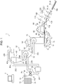
- Fig. 1 is a schematic view illustrating a configuration of a sheet manufacturing apparatus according to a first embodiment.
- the sheet manufacturing apparatus 1 of the embodiment includes a raw material supplying unit 10, a crushing unit 20, a defibrating unit 30, a classifying unit 40, a screening unit 50, an additive agent feeding unit 60, an accumulating unit 70, a heating and pressurizing unit 120, and the like.
- the sheet manufacturing apparatus includes a control unit 2 that controls these members described above.
- the raw material supplying unit 10 supplies wastepaper Pu or the like as a raw material to the crushing unit 20.
- the raw material supplying unit 10 includes, for example, a tray 11 to pile and store a plurality of wastepaper Pu and an automatic feeding mechanism 12 or the like which allows the wastepaper Pu to be continuously fed to the crushing unit 20.
- the wastepaper Pu to be supplied to the sheet manufacturing apparatus 1 may be, for example, an A4 size paper or the like which is currently the mainstream paper used in offices.
- the crushing unit 20 cuts the supplied wastepaper Pu into pieces of paper that are a few centimeters square.
- the crushing unit 20 includes crushing blades 21 and forms a unit in which the cutting width is larger than in a related art shredder. As a result of this, it is possible to easily cut the supplied wastepaper Pu into pieces of paper.
- the crushed paper is then supplied to the defibrating unit 30 via a tube 201.
- the defibrating unit 30 defibrates materials including fibers in air. More specifically, the defibrating unit 30 includes a rotary blade (not illustrated) and defibrates the crushed paper supplied from the crushing unit 20 by untangling processing into fibers.
- a defibration object an object to be defibrated by the defibrating unit 30
- a defibrated material an object which has passed through the defibrating unit 30 is referred to as a defibrated material.
- the defibrating unit 30 of the embodiment performs a dry-type defibrating process in the atmosphere (in air).
- the defibrating unit 30 By the defibrating process of the unit 30, coating materials or the like on paper, such as printed ink particles of inks, toners, and blur-preventing agent become particles (hereinafter, referred to as "ink particles") that are several tens of ⁇ m or less in size, separating from the fibers. Therefore, the defibrated materials exiting the defibrating unit 30 are fiber and ink particles obtained from the defibration of the pieces of paper. Furthermore, the defibrating unit 30 has a mechanism of generating airflow by rotating the rotary blade. The defibrated fibers are transferred to the classifying unit 40 in the air by an air stream via a tube 202. It is possible to separately provide an airflow generating device in the defibrating unit 30 for generating airflow for transporting the fiber defibrated to the classification unit 40 via the tube 202 on an as-needed basis.
- the classifying unit 40 classifies an introduced material by using the airflow.
- the defibrated material as the introduced material is classified into ink particles and fibers.
- the classifying unit 40 classifies by using the airflow the transported defibrated material into ink particles and fibers, by applying, for example, a cyclone.
- An airflow classifier other than a cyclone may be used.
- an airflow classifier other than the cyclone for example, an Elbow-jet, an eddy classifier, or the like may be used.
- the airflow classifier produces swirling air and performs separation by using a centrifugal force and the size or density of a substance to be classified such that it is possible to adjust a classification threshold by adjusting the speed or the centrifugal force of the airflow. Accordingly, the introduced material is separated into ink particles which are relatively small with lower density and fibers which are relatively large with higher density than ink particles.
- the classifying unit 40 of the embodiment uses a tangential inlet cyclone.
- the classifying unit 40 includes an introduction port 40a into which the introduced material is introduced from the defibrating unit 30, a cylindrical portion 41 onto which the introduction port 40a is attached in a tangential direction, a conical portion 42 which is connected to the lower part of the cylindrical portion 41, a lower discharge port 40b provided at the lower part of the conical portion 42, and an upper discharge port 40c provided at the upper central part of the cylindrical portion 41 for discharging fine particles.
- the diameter of the conical portion 42 becomes smaller in the vertically downward direction.
- the airflow containing the defibrated material guided in from the introduction port 40a of the classifying unit 40 is caused to move in a circular motion in the cylindrical portion 41 and the conical portion 42.
- a centrifugal force is applied to classify the guided-in defibrated material.
- the fiber material which is higher in density than the ink particles moves to the lower discharge port 40b, and the ink particles which are lower in density than the fiber material flows out from the upper discharge port 40c as fine particles in air.
- the ink particles are discharged from the upper discharge port 40c of the classifying unit 40.
- the discharged ink particles are collected in the receiving portion 80 via a tube 206 connected to the upper discharge port 40c.
- classified materials including fibers are transported in air from the lower discharge port 40b of the classifying unit 40 toward a screening unit 50 via a tube 203.
- the transportation of the classified materials from the classifying unit 40 to the screening unit 50 may be caused by the airflow during classification, or the classified materials may be transported by gravity from the classifying unit which is at a higher level, to the screening unit 50 which is at a lower level.
- a suction unit or the like for efficiently sucking short fiber mixtures from the upper air outlet 40c may be arranged at the upper discharge port 40c of the classification unit 40, the tube 206, or the like.
- Classification is not intended to divide the defibrated materials precisely by a certain size or density as a threshold.
- a relatively small fiber material may be discharged from the upper discharge port 40c along with the ink particles.
- ink particles with relatively high density may be discharged from the lower discharge port 40b along with fibers.
- the screening unit 50 screens the classified materials (defibrated materials) containing the fibers classified by the classifying unit 40 by causing the classified materials to pass through a sieve portion 51 having a plurality of openings. Further, more specifically, the screening unit 50 screens the classified materials containing the fibers classified by the classifying unit 40 into passing-through materials which pass through the openings and a residue which does not pass through the openings.
- the screening unit 50 of the embodiment includes a mechanism for distributing the classified materials in air by a rotating motion. The passing-through materials that pass through the openings as a result of the screening of the screening unit 50 are transported to the accumulating unit 70 side via a tube 204 from a passing-through material transferring unit 52.
- the residue which does not pass through the openings as a result of the screening of the screening unit 50 is returned to the defibrating unit 30 via a tube 205 as the defibration object.
- the residue can be re-used (recycled) without being discarded.
- the passing-through materials passing-through the openings as a result of the screening of the screening unit 50 are transported in air to the accumulating unit 70 via the tube 204.
- the transportation of the passing-through materials from the screening unit 50 to the accumulating unit 70 may be caused by an unillustrated blower which generates airflow, or the passing-through materials may be transported by gravity from the screening unit 50, which is at a higher level, to the accumulating unit 70, which is at a lower level.
- An additive agent feeding unit 60 which feeds a bonding resin (such as powder of a heat-curable resin or a thermoplastic resin) or the like to the transporting passing-through materials, is provided in an area between the screening unit 50 and the accumulating unit 70 in the tube 204.
- a bonding resin such as powder of a heat-curable resin or a thermoplastic resin
- an additive agent other than the bonding resin for example, a flame retardant, a whiteness enhancer, a sheet strengthening agent, a sizing agent,
- the additive agent feeding unit 60 includes a supplying unit 63 that supplies the additive agent to the tube 204 in air, a first tank 61 that communicates with the supplying unit 63, and a tank 62 that communicates with the first tank 61 and is detachable from the sheet manufacturing apparatus 1. Detailed configuration of the additive agent feeding unit 60 will be described later.
- the accumulating unit 70 is intended to permit accumulation of materials containing fibers and is intended to accumulate at least a portion of the defibrated materials defibrated at the defibrating unit 30 in air. More specifically, the accumulating unit 70 forms a web W by accumulating materials including the fibers and the bonding resin fed from the tube 204 and includes a mechanism for distributing the fibers evenly in air. Furthermore, the accumulating unit 70 has a moving portion that accumulates the defibrated material as a deposited material (web W) while moving.
- the moving portion of the embodiment is formed of tension rollers 72 and an endless mesh belt 73 stretched by the tension rollers 72 on which a mesh is formed.
- the web W according to the embodiment refers to a configuration of an object containing fibers and a bonding resin. Therefore, even in the case where the form such as the size of the web is changed due to heating, pressurizing, cutting, transporting, or the like, the web is still indicated as the web.
- a forming drum 71 to which the fibers and the bonding resin are fed is arranged in the accumulating unit 70.
- the forming drum 71 is provided with a screen having a plurality of small holes.
- the forming drum 71 rotates to evenly mix the bonding resin (additive agent) with the passing-through materials (fibers), as well as to evenly distribute the fiber and the mixture of the fiber and the bonding resin passing-through the small holes into the air.
- the mesh belt 73 is arranged below the forming drum 71. Furthermore, a suction device 75 is provided in the vertically downward direction of the forming drum 71 as a suction unit to generate airflow in the vertically downward direction via the mesh belt 73. With the suction device 75, it is possible to absorb the dispersed fibers in air on the mesh belt 73.
- the fibers or the like that pass through the porous screen on the surface of the forming drum 71 are accumulated on the mesh belt 73 by the suction power of the suction device 75.
- the mesh belt 73 moving in the one direction, the web W containing the fibers and the bonding resin which accumulate to form an elongated shape is formed.
- the mesh belt 73 may be metallic, resinous, or a nonwoven fabric, as long as the mesh belt 73 allows the airflow to pass through and the fibers to accumulate thereon.
- the suction device 75 may be configured from a sealed box with a window having the desired size opened below the mesh belt 73 to suction air from outside the window to produce negative pressure inside the box with respect to the outside air.
- the web W formed on the mesh belt 73 is transported according to a transfer direction (white arrow in Fig. 1 ) by rotation of the mesh belt 73.
- An intermediate transferring unit 90 is arranged as a peeling unit on the upper side of the mesh belt 73.
- the web W is peeled off the mesh belt 73 by the intermediate transferring unit 90 and transported to a pressing unit 110 side. That is, the sheet manufacturing apparatus has the peeling unit (intermediate transferring unit 90) which peels the deposited material (web W) off the moving portion (mesh belt 73) and that is able to transport the peeled deposited material (web W) to the pressing unit 110.
- the intermediate transferring unit 90 is configured in a manner in which the web W is transportable while the web W is being suctioned vertically upward (direction in which the web W is separated from the mesh belt 73).
- the intermediate transferring unit 90 is arranged so as to be spaced, from the mesh belt 73 in a vertically upward direction (direction perpendicular to the surface of the web W). Furthermore, the intermediate transferring unit 90 is arranged such that the mesh belt 73 and a portion of the intermediate transferring unit 90 are shifted downstream in the transport direction of the Web W.
- the transporting section of the intermediate transferring unit 90 is a section from the tension roller 72a on the downstream side of the mesh belt 73 to the pressing unit 110.
- the intermediate transferring unit 90 includes a transport belt 91, a plurality of tension rollers 92, and a suction chamber 93.
- the transport belt 91 is an endless mesh belt on which a mesh stretched by the tension rollers 92 is formed. By causing at least one of the tension rollers 92 to rotate automatically, the mesh belt 73 rotates (moves) in one direction.
- the suction chamber 93 is arranged on the inner side of the transport belt 91, has a hollow box shape having a top surface and four side surfaces in contact with the top surface, and has a bottom surface (the surface facing the transport belt 91 positioned below) which is open.
- the suction chamber 93 is provided with a suction unit generating airflow (suction force) to the suction chamber 93. Then, the inner space of the suction chamber 93 is suctioned by driving the suction unit, and the air flows from the bottom surface of the suction chamber 93.
- airflow directed over the suction chamber 93 is generated, thereby, it is possible to adsorb the web W onto the transport belt 91 by sucking the web W from the upper side of the web W.
- the transport belt 91 moves (circulates) by the rotation of the tension rollers 92.
- the web W is transported toward the pressing unit 110.
- the suction chamber 93 is viewed from above, a portion of the suction chamber 93 overlaps the mesh belt 73. Since the suction chamber 93 is located on the downstream side of the suction device 75 at a position that does not overlap the suction device 75, the web W on the mesh belt 73 may be adsorbed onto the transport belt 91 and peeled from the mesh belt 73 in a position facing the suction chamber 93.
- the tension rollers 92 rotate so as to move the transport belt 91 at the same speed as the mesh belt 73. If there is a difference in the speed of the mesh belt 73 and the transport belt 91, the web W may be pulled, resulting in buckling or breaking. However, by maintaining the same speed, this may be prevented.
- a pressing unit 110 is arranged on the downstream side of the intermediate transferring unit 90 in the transfer direction of the web W.
- the pressing unit 110 is formed of a pair of pressing rollers 111 and 112 and pressurizes the transporting web W.
- the web W is pressurized by the pressing unit 110, such that the thickness of the web W becomes approximately 1/5 to 1/30 the thickness of the web W that is formed by the accumulating unit 70.
- it is possible to improve the strength of the web W.
- a heating and pressurizing unit 120 is arranged on the downstream side of the pressing unit 110 in the transfer direction of the web W.
- the heating and pressurizing unit 120 heats and pressurizes the web W that has accumulated as the deposited materials in the accumulating unit 70.
- the heating and pressurizing unit 120 bonds the fibers contained in the web W with the bonding resin.
- the heating and pressurizing unit 120 of the embodiment is formed of a pair of heating rollers 121 and 122.
- a heating element such as a heater is provided at the center of each rotating shaft of the heating rollers 121 and 122.
- the bonding resin melts enabling the resin to easily entangle with the fibers, and the fiber intervals become shorter, increasing the number of contact points between the fibers.
- a first cutting portion 130a for cutting the web W in the transfer direction of the web W and a second cutting portion 130b for cutting the web W in the direction crossing the transfer direction of the web W are arranged.
- the first cutting portion 130a is, for example, a slitter, cutting the web W according to a predetermined cutting position in the conveying direction of the web W.
- the second cutting portion 130b is, for example, a rotary cutter, cutting the continuous form of the web W according to a set cutting position to a predetermined length in cut-sheet form. As a result, a desired size of a sheet Pr (web W) is formed.
- the cut sheet Pr is stacked in a stacker 160 or the like.
- the sheet manufacturing apparatus may be formed such that the sheet W, remaining in a continuous form, is wound by a winding roller. As described above, it is possible to produce the sheet Pr in the sheet manufacturing apparatus 1.
- the "sheet” refers mainly to a substance in which the raw material contains fibers such as wastepaper and pure pulp made into a sheet form.
- the sheet may have a board form or a web form (shape having irregularities).
- the raw material may be plant fibers such as cellulose, plastic fibers such as polyethylene terephthalate (PET), chemical fibers such as polyester, or animal fibers such as sheep wool or silk.
- PET polyethylene terephthalate
- the sheet as used in the invention is divided into paper and non-woven fabric.
- Paper includes forms such as a thin sheet form, including recording paper and the like for the purpose of writing or printing, wallpaper, wrapping paper, colored paper, Kent paper, and the like.
- Non-woven fabric is thicker and has lower strength than paper, including non-woven fabric, fiber board, tissue paper, paper towel, cleaner, filter, water absorbing material, a sound absorbing body, cushioning material, a mattress, and the like.
- wastepaper refers mainly to a printed paper. However, if the raw material is formed as a paper, it is regarded as wastepaper regardless of whether or not it has been used.
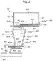
- FIG. 2 and Fig. 3 are schematic views illustrating the configuration of the additive agent feeding unit.
- Fig. 2 is the schematic view for a case in which a first tank and a second tank are connected.
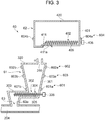
- Fig. 3 is the schematic view for a case in which the first tank and the second tank are disconnected.
- the additive agent feeding unit 60 includes a supplying unit 63 that supplies the additive agent in air, the first tank that communicates with the supplying unit 63 and stores the additive agent, and the second tank 62 that communicates with the first tank 61, is detachable from the sheet manufacturing apparatus 1, and stores the additive agent.
- the supplying unit 63 includes an opening 63a and is configured such that the additive agent being transported from the first tank 61 side is supplied to the tube 204 via the opening 63a.
- the first tank 61 includes a first container 61 to store the additive agent.
- the first container 301 of the embodiment has a substantially conical shape and is arranged such that the cross-sectional area in the horizontal direction of the first container 301 gradually decreases downward.
- a transferring unit 302 is arranged below the first container 301.
- a communication route 303 which causes the first container 301 and the supplying unit 63 to communicate, and a first screw feeder 304 are arranged.
- the first screw feeder 304 includes a spiral screw portion 305 and a motor 306 connected to the screw portion 305. By driving the motor 306, the screw portion 305 rotates. Thus, the additive agent in the first container 301 may be transported quantitatively to the opening 63a side.
- a second tank 62 is arranged above the first container 301 of the first tank 61.
- the second tank 62 includes a second container 401 to store the additive agent.
- the second container 401 of the embodiment has a substantially rectangular parallelepiped shape.
- the second tank 62 is user detachable, whereas the first tank 61 is secure and not detachable by the user.
- a second screw feeder 402 is arranged as a transferring unit to transport the additive agent from the second tank 62 to the first tank 61.
- the second screw feeder 402 includes a spiral screw portion 405 and a motor 406 connected to the screw portion 405.
- an opening 310 and an opening 410 connected to the opening 310 are provided above the first container 301 of the first tank 61.
- the screw portion 405 By driving the motor 406, the screw portion 405 is rotated, thus the additive agent stored in the second container 401 may be quantitatively transported to the first tank 61 via the openings 410 and 310.
- a valve 411 is provided at the opening 410 of the second tank 62.
- the valve 411 is provided with a lid 411a and a spring member (not illustrated) biasing the lid 411a, and the lid 411a is formed to be movable.
- the opening 410 is able to open and close according to the movement of the lid 411a.
- the lid 411a is slid, and the state of the opening 410 becomes an open state.
- the first tank 61 has a first detection unit 601 that is capable of detecting the absence of the additive agent in the first tank 61.
- the first detecting unit 601 is, for example, formed of a photodetector, which includes a light emitting portion 601a for emitting light and a light receiving portion 601b for receiving light emitted from the light emitting portion 601a.
- the light emitting element of the light emitting portion 601a may be, for example, a light emitting diode (LED) element, and the light receiving section 601b may include a phototransistor or a photo IC and the like.
- the light emitting portion 601a and the light receiving portion 601b are arranged on the outer surface of the lowermost position of the first container 301.
- a resin material or the like having a light-transmitting property form the part of the first container 301 at which the light emitting portion 601a and the light receiving portion 601b are arranged. Therefore, light emitted from the light emitting portion 601a of the first detection unit 601 is transmitted through the first container 301 and received by the light receiving portion 601b.
- the absence of the additive agent in the first detection unit 601 may be detectable in various degrees.
- a complete absence of the additive agent in the first tank 61 may be directly detectable, whereas a near-end state in which the additive agent in the first tank 61 is almost depleted (for example, a state in which the additive agent in the first tank 61 is 5% or less with regards to a full state) may also be detectable.
- the first detection unit 601 is connected to the control unit 2, and detection data from the first detection unit 601 is sent to the control unit 2.
- the first tank 61 includes a second detection unit 602 which is capable of detecting that the amount of the additive agent in the first tank 61 is at the upper limit.
- the configuration of the second detection unit 602 is the same as the configuration of the first detecting unit 601, and the second detection unit is formed of a light emitting portion 602a and a light receiving portion 602b.
- the light emitting portion 602a and the light receiving portion 602b are arranged on the outer surface of the upper position of the first container 301.
- a resin material or the like having a light-transmitting property form the part of the first container 301 at which the light emitting portion 602a and the light receiving portion 602b are arranged. Therefore, light emitted from the light emitting portion 602a of the second detection unit 602 is transmitted through the first container 301 and is received by the light receiving portion 602b.
- the second detection unit 602 is connected to the control unit 2, and detection data from the second detection unit 602 is sent to the control unit 2.
- the first tank 61 includes a third detection unit 603 between the first detection unit 601 and the second detection unit 602 in a vertical direction.
- the configuration of the third detection unit 603 is the same as the configuration of the first detecting section 601, and the third detection unit 603 is formed of a light emitting portion 603a and a light receiving portion 603b.
- the light emitting portion 603a is arranged between the light emitting portion 601a and the light projecting portion 602a in the vertical direction
- the light receiving portion 603b is arranged between the light receiving portion 601b and the light receiving portion 602b in the vertical direction. This makes it possible to obtain the timing of supplying the additive agent from the second tank 62 to first tank 61.
- a resin material or the like having a light-transmitting property form the part of the first container 301 at which the light emitting portion 603a and the light receiving portion 603b are arranged. Therefore, light emitted from the light emitting portion 603a of the third detection unit 603 is transmitted through the first container 301 and is received by the light receiving portion 603b.
- the third detection unit 603 is connected to the control unit 2, and detection data from the third detection unit 603 is sent to the control unit 2.
- a hole 320 is provided at the upper side of the first tank 61.
- the hole 320 is provided above the second detection unit 602 at the top part of the first container 301.
- the second tank 62 includes a fourth detection unit 604 that is capable of detecting the absence of the additive agent in the second tank 62.
- the configuration of the fourth detection unit 604 is the same as the configuration of the first detection unit 601, and fourth detection unit 604 is formed of a light emitting portion 604a and a light receiving portion 604b.
- the light emitting portion 604a and the light receiving portion 604b are arranged on the outer surface of the lower position of the second container 401.
- a resin material or the like having a light-transmitting property form the part of the second container 401 at which the light emitting portion 604a and the light receiving portion 604b are arranged.
- the absence of the additive agent in the fourth detection unit 604 may be detectable in certain degrees. For example, a complete absence of the additive agent in the second tank 62 may be directly detectable, whereas a near-end state in which the additive agent in the second tank 62 is almost depleted (for example, a state in which the additive agent in the second tank 62 is 5% or less with regards to a full state) may also be detectable.
- the fourth detection unit 604 is connected to the control unit 2, and detection data from the fourth detection unit 604 is sent to the control unit 2.
- the second tank 62 is formed to be detachable from the first tank 61 (sheet manufacturing apparatus 1) by the user, as illustrated in Figure 3 .
- the additive agent in the second tank 62 may be replenished when the second tank 62 is in a standalone state.
- the first tank 61 is capable of supplying the additive agent to the tube 204. Therefore, it is possible to continue the production of the sheet W (sheet Pr) while the second tank 62 empty of the additive agent is replaced with the second tank 62 replenished with the additive agent or a new second tank 62 filled with the additive agent.
- the lid 411a of the valve 411 is moved by a spring bringing the opening 410 into a closed state, as illustrated in Fig. 3 .
- the additive agent remaining in the second tank 62 is less likely to be spilled outside.
- an openable and closable lid member 420 is provided at the opposite side the valve 411 in the second container 401 of the second tank 62 (upper side of the second container 401). By opening the lid member 420, it is possible to replenish the additive agent in the second tank 62. Therefore, it is possible to replenish the additive agent in a state in which the second container 401 (second tank 62) is detached from the sheet manufacturing apparatus 1.
- replenishing may be difficult due to other members being present. Furthermore, there is a possibility of the additives spilling from the second container 401, soiling the inside of the sheet manufacturing apparatus 1.
- the replenishing becomes easier, and the inside of the sheet manufacturing apparatus 1 will not be soiled.
- the new second tank 62 filled with the additive agent may be used.
- a control method for the sheet manufacturing apparatus will be described.
- a control method according to the additive agent feeding unit of the sheet manufacturing apparatus 1 will primarily be described.
- Fig. 4 to Fig. 6 are flowcharts illustrating the control method of the sheet manufacturing apparatus.
- the first detecting unit 601 is set to a detectable state in step S11 in Fig. 4 .
- step S12 it is determined as to whether or not detection has been made by the first detection unit 601. That is, a determination is made as to whether or not the additive agent is absent in the first tank 61. Then, when it is determined that the additive agent is absent in the first tank 61 (Yes), the processing proceeds to step S13. When it is determined that the additive agent is present in the first tank 61 in step S12 (No), the processing returns to step S11.
- the operation of the sheet manufacturing apparatus may be stopped. More specifically, operation of at least the members of the upstream side of the additive agent feeding unit 60 (for example, the raw material supplying unit 10, the crushing unit 20, the defibrating unit 30, the classifying unit 40, the screening unit 50 and the like) in the supply direction of the raw material or other material and the like is stopped. This makes it possible to avoid continuing the production of the web W in a state in which the additive agent is not supplied to the fiber supplied from the pipe 204.
- the members of the upstream side of the additive agent feeding unit 60 for example, the raw material supplying unit 10, the crushing unit 20, the defibrating unit 30, the classifying unit 40, the screening unit 50 and the like
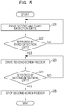
- the second and third detection units 602 and 603 are set to detectable states in step S21 in Fig. 5 .
- step S22 it is determined whether or not detection has been made by the third detection unit 603. That is, a determination is made as to whether or not to transport the additive agent to the first tank 61. Then, when a determination is made to transport the additive agent to the first tank 61 (Yes), the processing proceeds to step S23. When a determination is made not to transport the additive agent to the first tank 61 in step S22 (No), the processing returns to step S21.
- step S23 the second screw feeder 402 is set.
- the additive agent in the second tank 62 is transported to the first tank 61 via the openings 410 and 310.
- step S24 it is determined whether or not detection has been made by the second detection unit 602. That is, a determination is made as to whether or not the amount of the additive agent in the first tank 61 is at the upper limit. Then, when it is determined that the amount of the additive agent in the first tank 61 is at the upper limit (Yes), the processing proceeds to step S25. When it is determined that the amount of the additive agent in the first tank 61 is not at the upper limit in step S24 (No), the processing returns to step S23.
- step S25 the driving of the second screw feeder 402 is stopped.
- the transportation of the additive agent from the second tank 62 to the first tank 61 is stopped. Therefore, the start and end timings of the transportation of the additive agent from the second tank 62 to first tank 61 become clear.
- the second detection unit detecting that the amount of the additive agent is at the upper limit, it is possible to prevent leakage of the additive agent from the hole 320, as well as to prevent compression of the additive agent by the drive of the second screw feeder 402 continuing in a state in which the first tank 61 is filled with the additive agent.
- the fourth detection unit 604 is set to a detectable state in step S31 in Fig. 6 .
- step S32 it is determined whether or not detection has been made by the fourth detection unit 604. That is, a determination is made as to whether or not the additive agent is absent in the second tank 62. Then, when it is determined that the additive agent is absent in the second tank 62 (Yes), the processing proceeds to step S33. When it is determined that the additive agent is present in the second tank 62 in step S32 (No), the processing returns to step S31.
- step S33 the driving of the second screw feeder 402 is stopped. Furthermore, a notification is output to a display unit such as an LED lamp or an LCD panel to notify the user that there is no additive agent in the second tank 62. Then, as illustrated in Fig. 3 , the user detaches the second tank 62 from the first tank 61 and replaces the empty second tank 62 with a second tank 62 filled with the additive agent.
- a display unit such as an LED lamp or an LCD panel
- the control method according to the first detection unit 601, the control methods according to the second and third detection units 602 and 603, and the control method according to the fourth detection unit 604 are executed in parallel. Furthermore, the priority is highest in the order of the control method according to the first detection unit 601, the control method according to the fourth detection unit 604, and the control methods according to the second and third detection units 602 and 603. That is, when detection is made by the first detection unit 601, the control method according to the fourth detection unit 604 and the control methods according to the second and third detection units 602 and 603 are stopped. Furthermore, when detection is made by the fourth detection unit 604, the control methods according to the second and third detection units 602 and 603 are stopped.
- the additive agent when detection is made by the third detection unit 603 which is located above the first detection unit 601, the additive agent is transported from the second tank 62 to the first tank 61.
- the transportation of the additive agent stops.
- the additive agent in the second tank 62 is depleted, the amount of additive agent inside the first tank 61 will be at or more than the level of the third detection unit 603. Therefore, even when the additive agent in the second tank 62 is depleted, it is possible to continue the production of the sheet with the additive agent in the first tank 61.
- the additive agent feeding unit 60 includes the supplying unit 63, the first tank 61, and the second tank 62.
- the second tank 62 is attached in a detachable manner to the first tank 61.
- the invention is not limited to the above-mentioned embodiment. It is possible to add various kinds of changes and improvements or the like to the above-mentioned embodiment. Modified examples are described hereinafter.
- the first container 301 of the first tank 61 has a substantially conical shape.
- the shape of the first container 301 is not limited to this.
- the shape of the first container 301 may be a rectangular shape, a quadrangular pyramid shape, or the like. Even in this manner, it is possible to obtain the same effect as the above.
- the shape of the second container 401 of the second tank 62 is not limited to a substantially rectangular shape, as described above.
- the second container 401 and the second screw feeder 402 as the transferring unit are configured as an integral structure.
- the configuration is not limited thereto.
- the second container 401 and the second screw feeder 402 may be separate structures. Even in this manner, it is possible to obtain the same effect as the above.
- the second screw feeder 402 as the transferring unit is provided in the second tank 62.
- the configuration of the transferring unit is not limited thereto.
- a valve mechanism may be used as the transferring unit. Even in this manner, it is possible to transport the additive agent from the second tank 62 to the first tank 61.
- the additive agent transported from the first tank 61 side is supplied to the tube 204 via the opening 63a.
- the additive agent may be supplied to the screening unit 50 or the accumulating unit 70.
- the first screw feeder 304 or the second screw feeder 402 stops.
- the screw feeder may stop after rotating for a predetermined number of times. Since the screw feeder may supply the additive agent quantitatively, the screw feeder may be stopped on the assumption that the additive agent became depleted after supplying a fixed amount when the detection is made by each detector.
- the fourth detection unit 604 is provided on the second tank 62.
- the configuration is not limited thereto.
- the detection unit 604 may be provided in the sheet manufacturing apparatus 1 and may be configured when the second tank 62 is attached so that the detection unit 604 is arranged opposite to the part on the second container 401 having the light-transmitting property.
Landscapes
- Engineering & Computer Science (AREA)
- Mechanical Engineering (AREA)
- Physics & Mathematics (AREA)
- Life Sciences & Earth Sciences (AREA)
- Electromagnetism (AREA)
- Chemical Kinetics & Catalysis (AREA)
- General Chemical & Material Sciences (AREA)
- Wood Science & Technology (AREA)
- Chemical & Material Sciences (AREA)
- Fluid Mechanics (AREA)
- General Physics & Mathematics (AREA)
- Thermal Sciences (AREA)
- Manufacturing & Machinery (AREA)
- Forests & Forestry (AREA)
- Textile Engineering (AREA)
- Nonwoven Fabrics (AREA)
- Dry Formation Of Fiberboard And The Like (AREA)
Description
- The present invention relates to a sheet manufacturing apparatus.
- To date, a method has been used in which a binder is supplied from a binder vessel while defibrating a wastepaper to manufacture a molded product made of fiber material such as a mixture of wastepaper fibers and a binder.
JP-A-7-3603 - However, such a method is problematic in that when the binder in the binder vessel is depleted, it is necessary to stop an apparatus temporarily and to supply the binder to the binder vessel before restarting the apparatus, hence productivity may be lowered. Furthermore, when replenishing the binder in the binder vessel directly, there is a possibility that the binder spills from the binder vessel.
-
US 2014/290888 discloses a sheet manufacturing apparatus that includes a measuring unit configured to measure thickness and air permeability of a defibration object containing fibers, a defibrating unit configured to dry-defibrate the defibration object, and a classifying unit configured to separate and remove, by airflow classification, foreign substances other than the fibers from the defibrated material defibrated at the defibrating unit. - A sheet manufacturing apparatus according to an aspect of the present invention is defined in claim 1.
- With this configuration, the sheet manufacturing apparatus includes two tanks, i.e., a first tank and a second tank, that are used to store the additive agent, and the second tank is detachably provided to the first tank. Therefore, if the additive agent in the second tank is depleted, it is possible to supply the additive agent from the first tank. Thus, it is possible to continue the manufacturing of the sheet without stopping operation of the sheet manufacturing apparatus. Furthermore, the second tank is detachable from the first tank. Therefore, it is possible to continue the manufacturing of the sheet by supplying the additive agent from the first tank, even while the second tank is detached from the first tank. Thus, even if a user does not have the second tank to be replaced, the user does not have to stop the manufacturing of the sheet. In addition, it is possible to replenish the additive agent by attaching the second tank to the first tank, thus improving the operability at the time of replenishing the additive agent and preventing staining or spilling of the additive agent.
- Preferably, the first tank includes a first detection unit capable of detecting the absence of the additive agent in the first tank.
- When the supplying unit supplies the additive agent, the amount of the additive agent stored in the first tank is reduced. When the amount of the additive agent stored in the first tank is reduced, the additive agent in the second tank is supplied to the first tank. With this configuration, the absence of the additive agent in the first tank is detectable. Therefore, it is possible to prevent the additive agent from not being supplied during the manufacturing of the sheet.
- Preferably, the sheet manufacturing apparatus further includes a transferring unit configured to transport the additive agent from the second tank to the first tank. The first tank includes a second detection unit capable of detecting that the amount of the additive agent in the first tank reaches an upper limit.
- With this configuration, since the second detection unit detects the amount of the additive agent stored in the first tank, it is possible to accurately obtain the amount of the additive agent supplied to the first tank from the second tank.
- Preferably, the first tank includes a third detection unit between the first detection unit and the second detection unit in a vertical direction.
- With this configuration, since the third detection unit detects the amount of the additive agent stored in the first tank, it is possible to know the timing for supplying the additive agent to the first tank from the second tank.
- Preferably, the first tank includes a hole configured to communicate with the outside of the first tank on the upper side thereof.
- With this configuration, when the additive agent is introduced into the first tank, since air in the first tank escapes via the hole, the additive agent in the second tank is easily transported to the first tank.
- Preferably, the second tank includes a fourth detection unit capable of detecting the absence of the additive agent in the second tank.
- With this configuration, it is possible to detect the absence of the additive agent in the second tank.
- Embodiments of the invention will now be described by way of example only with reference to the accompanying drawings, wherein like numbers reference like elements.
-
Fig. 1 is a schematic view illustrating a configuration of a sheet manufacturing apparatus. -
Fig. 2 is a schematic view illustrating a configuration of an additive agent feeding unit. -
Fig. 3 is a schematic view illustrating a configuration of the additive agent feeding unit. -
Fig. 4 is a flowchart illustrating a control method of the sheet manufacturing apparatus. -
Fig. 5 is a flowchart illustrating a control method of the sheet manufacturing apparatus. -
Fig. 6 is a flowchart illustrating a control method of the sheet manufacturing apparatus. - Hereinafter, a preferred embodiment of the invention will be described with reference to the drawings. In each diagram below, in order to make the size of each member or the like large enough to be recognized, measures of such members or the like are illustrated differently from the actual measures.
- The sheet manufacturing apparatus is, for example, an apparatus for manufacturing a sheet by heating and pressurizing a material containing a fiber and an additive agent, based on a technique to form a raw material (defibration object) Pu such as a pure pulp sheet or wastepaper into a new sheet Pr. Hereinafter, a configuration of the sheet manufacturing apparatus will be described in detail.
-
Fig. 1 is a schematic view illustrating a configuration of a sheet manufacturing apparatus according to a first embodiment. As illustrated inFig. 1 , the sheet manufacturing apparatus 1 of the embodiment includes a rawmaterial supplying unit 10, a crushingunit 20, adefibrating unit 30, a classifyingunit 40, ascreening unit 50, an additiveagent feeding unit 60, an accumulatingunit 70, a heating and pressurizingunit 120, and the like. Furthermore, the sheet manufacturing apparatus includes a control unit 2 that controls these members described above. - The raw
material supplying unit 10 supplies wastepaper Pu or the like as a raw material to the crushingunit 20. The rawmaterial supplying unit 10 includes, for example, atray 11 to pile and store a plurality of wastepaper Pu and anautomatic feeding mechanism 12 or the like which allows the wastepaper Pu to be continuously fed to the crushingunit 20. The wastepaper Pu to be supplied to the sheet manufacturing apparatus 1 may be, for example, an A4 size paper or the like which is currently the mainstream paper used in offices. - The crushing
unit 20 cuts the supplied wastepaper Pu into pieces of paper that are a few centimeters square. The crushingunit 20 includes crushingblades 21 and forms a unit in which the cutting width is larger than in a related art shredder. As a result of this, it is possible to easily cut the supplied wastepaper Pu into pieces of paper. The crushed paper is then supplied to thedefibrating unit 30 via atube 201. - The defibrating
unit 30 defibrates materials including fibers in air. More specifically, thedefibrating unit 30 includes a rotary blade (not illustrated) and defibrates the crushed paper supplied from the crushingunit 20 by untangling processing into fibers. In the invention, an object to be defibrated by thedefibrating unit 30 is referred to as a defibration object, and an object which has passed through thedefibrating unit 30 is referred to as a defibrated material. Thedefibrating unit 30 of the embodiment performs a dry-type defibrating process in the atmosphere (in air). By the defibrating process of theunit 30, coating materials or the like on paper, such as printed ink particles of inks, toners, and blur-preventing agent become particles (hereinafter, referred to as "ink particles") that are several tens of µm or less in size, separating from the fibers. Therefore, the defibrated materials exiting the defibratingunit 30 are fiber and ink particles obtained from the defibration of the pieces of paper. Furthermore, the defibratingunit 30 has a mechanism of generating airflow by rotating the rotary blade. The defibrated fibers are transferred to the classifyingunit 40 in the air by an air stream via atube 202. It is possible to separately provide an airflow generating device in thedefibrating unit 30 for generating airflow for transporting the fiber defibrated to theclassification unit 40 via thetube 202 on an as-needed basis. - The classifying
unit 40 classifies an introduced material by using the airflow. In the embodiment, the defibrated material as the introduced material is classified into ink particles and fibers. The classifyingunit 40 classifies by using the airflow the transported defibrated material into ink particles and fibers, by applying, for example, a cyclone. An airflow classifier other than a cyclone may be used. In this case, as an airflow classifier other than the cyclone, for example, an Elbow-jet, an eddy classifier, or the like may be used. The airflow classifier produces swirling air and performs separation by using a centrifugal force and the size or density of a substance to be classified such that it is possible to adjust a classification threshold by adjusting the speed or the centrifugal force of the airflow. Accordingly, the introduced material is separated into ink particles which are relatively small with lower density and fibers which are relatively large with higher density than ink particles. - The classifying
unit 40 of the embodiment uses a tangential inlet cyclone. The classifyingunit 40 includes anintroduction port 40a into which the introduced material is introduced from thedefibrating unit 30, acylindrical portion 41 onto which theintroduction port 40a is attached in a tangential direction, aconical portion 42 which is connected to the lower part of thecylindrical portion 41, alower discharge port 40b provided at the lower part of theconical portion 42, and anupper discharge port 40c provided at the upper central part of thecylindrical portion 41 for discharging fine particles. The diameter of theconical portion 42 becomes smaller in the vertically downward direction. - In the classification process, the airflow containing the defibrated material guided in from the
introduction port 40a of the classifyingunit 40 is caused to move in a circular motion in thecylindrical portion 41 and theconical portion 42. Thus, a centrifugal force is applied to classify the guided-in defibrated material. The fiber material which is higher in density than the ink particles moves to thelower discharge port 40b, and the ink particles which are lower in density than the fiber material flows out from theupper discharge port 40c as fine particles in air. Then, the ink particles are discharged from theupper discharge port 40c of the classifyingunit 40. The discharged ink particles are collected in the receivingportion 80 via atube 206 connected to theupper discharge port 40c. Meanwhile, classified materials including fibers are transported in air from thelower discharge port 40b of the classifyingunit 40 toward ascreening unit 50 via atube 203. The transportation of the classified materials from the classifyingunit 40 to thescreening unit 50 may be caused by the airflow during classification, or the classified materials may be transported by gravity from the classifying unit which is at a higher level, to thescreening unit 50 which is at a lower level. Accordingly, a suction unit or the like for efficiently sucking short fiber mixtures from theupper air outlet 40c may be arranged at theupper discharge port 40c of theclassification unit 40, thetube 206, or the like. Classification is not intended to divide the defibrated materials precisely by a certain size or density as a threshold. Nor is it intended to divide the defibrated materials precisely into fibers and ink particles. In some cases, a relatively small fiber material may be discharged from theupper discharge port 40c along with the ink particles. In addition, in some cases, ink particles with relatively high density may be discharged from thelower discharge port 40b along with fibers. - The
screening unit 50 screens the classified materials (defibrated materials) containing the fibers classified by the classifyingunit 40 by causing the classified materials to pass through asieve portion 51 having a plurality of openings. Further, more specifically, thescreening unit 50 screens the classified materials containing the fibers classified by the classifyingunit 40 into passing-through materials which pass through the openings and a residue which does not pass through the openings. Thescreening unit 50 of the embodiment includes a mechanism for distributing the classified materials in air by a rotating motion. The passing-through materials that pass through the openings as a result of the screening of thescreening unit 50 are transported to the accumulatingunit 70 side via atube 204 from a passing-throughmaterial transferring unit 52. Meanwhile, the residue which does not pass through the openings as a result of the screening of thescreening unit 50 is returned to thedefibrating unit 30 via atube 205 as the defibration object. Thus, the residue can be re-used (recycled) without being discarded. - The passing-through materials passing-through the openings as a result of the screening of the
screening unit 50 are transported in air to the accumulatingunit 70 via thetube 204. The transportation of the passing-through materials from thescreening unit 50 to the accumulatingunit 70 may be caused by an unillustrated blower which generates airflow, or the passing-through materials may be transported by gravity from thescreening unit 50, which is at a higher level, to the accumulatingunit 70, which is at a lower level. An additiveagent feeding unit 60, which feeds a bonding resin (such as powder of a heat-curable resin or a thermoplastic resin) or the like to the transporting passing-through materials, is provided in an area between thescreening unit 50 and the accumulatingunit 70 in thetube 204. As an additive agent other than the bonding resin, for example, a flame retardant, a whiteness enhancer, a sheet strengthening agent, a sizing agent, an absorption modifier, a fragrance, a deodorant, or the like may be fed. - The additive
agent feeding unit 60 includes a supplyingunit 63 that supplies the additive agent to thetube 204 in air, afirst tank 61 that communicates with the supplyingunit 63, and atank 62 that communicates with thefirst tank 61 and is detachable from the sheet manufacturing apparatus 1. Detailed configuration of the additiveagent feeding unit 60 will be described later. - The accumulating
unit 70 is intended to permit accumulation of materials containing fibers and is intended to accumulate at least a portion of the defibrated materials defibrated at thedefibrating unit 30 in air. More specifically, the accumulatingunit 70 forms a web W by accumulating materials including the fibers and the bonding resin fed from thetube 204 and includes a mechanism for distributing the fibers evenly in air. Furthermore, the accumulatingunit 70 has a moving portion that accumulates the defibrated material as a deposited material (web W) while moving. The moving portion of the embodiment is formed oftension rollers 72 and anendless mesh belt 73 stretched by thetension rollers 72 on which a mesh is formed. Furthermore, by causing at least one of thetension rollers 72 to rotate automatically, themesh belt 73 rotates (moves) in one direction. The web W according to the embodiment refers to a configuration of an object containing fibers and a bonding resin. Therefore, even in the case where the form such as the size of the web is changed due to heating, pressurizing, cutting, transporting, or the like, the web is still indicated as the web. - Firstly, as a mechanism to evenly distribute the fibers in air, a forming
drum 71 to which the fibers and the bonding resin are fed is arranged in the accumulatingunit 70. Thus, it is possible to evenly mix the bonding resin (additive agent) with the passing-through materials (fibers) by rotationally driving the formingdrum 71. The formingdrum 71 is provided with a screen having a plurality of small holes. The formingdrum 71 rotates to evenly mix the bonding resin (additive agent) with the passing-through materials (fibers), as well as to evenly distribute the fiber and the mixture of the fiber and the bonding resin passing-through the small holes into the air. - The
mesh belt 73 is arranged below the formingdrum 71. Furthermore, asuction device 75 is provided in the vertically downward direction of the formingdrum 71 as a suction unit to generate airflow in the vertically downward direction via themesh belt 73. With thesuction device 75, it is possible to absorb the dispersed fibers in air on themesh belt 73. - The fibers or the like that pass through the porous screen on the surface of the forming
drum 71 are accumulated on themesh belt 73 by the suction power of thesuction device 75. At this time, with themesh belt 73 moving in the one direction, the web W containing the fibers and the bonding resin which accumulate to form an elongated shape is formed. By performing the distribution from the formingdrum 71 and the movement of themesh belt 73 continuously, a continuous belt-like web W is formed. Themesh belt 73 may be metallic, resinous, or a nonwoven fabric, as long as themesh belt 73 allows the airflow to pass through and the fibers to accumulate thereon. If the hole diameters of themesh belt 73 are too large, the fibers may become caught in the mesh, thus forming an uneven surface on the web W (or sheet). On the other hand, if the hole diameters of the mesh are too small, it is difficult for thesuction device 75 to form stable airflow. For this reason, the hole diameters of the mesh are preferably appropriately adjusted. Thesuction device 75 may be configured from a sealed box with a window having the desired size opened below themesh belt 73 to suction air from outside the window to produce negative pressure inside the box with respect to the outside air. - The web W formed on the
mesh belt 73 is transported according to a transfer direction (white arrow inFig. 1 ) by rotation of themesh belt 73. Anintermediate transferring unit 90 is arranged as a peeling unit on the upper side of themesh belt 73. The web W is peeled off themesh belt 73 by theintermediate transferring unit 90 and transported to apressing unit 110 side. That is, the sheet manufacturing apparatus has the peeling unit (intermediate transferring unit 90) which peels the deposited material (web W) off the moving portion (mesh belt 73) and that is able to transport the peeled deposited material (web W) to thepressing unit 110. Theintermediate transferring unit 90 is configured in a manner in which the web W is transportable while the web W is being suctioned vertically upward (direction in which the web W is separated from the mesh belt 73). Theintermediate transferring unit 90 is arranged so as to be spaced, from themesh belt 73 in a vertically upward direction (direction perpendicular to the surface of the web W). Furthermore, theintermediate transferring unit 90 is arranged such that themesh belt 73 and a portion of theintermediate transferring unit 90 are shifted downstream in the transport direction of the Web W. The transporting section of theintermediate transferring unit 90 is a section from the tension roller 72a on the downstream side of themesh belt 73 to thepressing unit 110. - The
intermediate transferring unit 90 includes atransport belt 91, a plurality oftension rollers 92, and asuction chamber 93. Thetransport belt 91 is an endless mesh belt on which a mesh stretched by thetension rollers 92 is formed. By causing at least one of thetension rollers 92 to rotate automatically, themesh belt 73 rotates (moves) in one direction. - The
suction chamber 93 is arranged on the inner side of thetransport belt 91, has a hollow box shape having a top surface and four side surfaces in contact with the top surface, and has a bottom surface (the surface facing thetransport belt 91 positioned below) which is open. In addition, thesuction chamber 93 is provided with a suction unit generating airflow (suction force) to thesuction chamber 93. Then, the inner space of thesuction chamber 93 is suctioned by driving the suction unit, and the air flows from the bottom surface of thesuction chamber 93. Thus, airflow directed over thesuction chamber 93 is generated, thereby, it is possible to adsorb the web W onto thetransport belt 91 by sucking the web W from the upper side of the web W. Then, thetransport belt 91 moves (circulates) by the rotation of thetension rollers 92. Thus, the web W is transported toward thepressing unit 110. Furthermore, when thesuction chamber 93 is viewed from above, a portion of thesuction chamber 93 overlaps themesh belt 73. Since thesuction chamber 93 is located on the downstream side of thesuction device 75 at a position that does not overlap thesuction device 75, the web W on themesh belt 73 may be adsorbed onto thetransport belt 91 and peeled from themesh belt 73 in a position facing thesuction chamber 93. Thetension rollers 92 rotate so as to move thetransport belt 91 at the same speed as themesh belt 73. If there is a difference in the speed of themesh belt 73 and thetransport belt 91, the web W may be pulled, resulting in buckling or breaking. However, by maintaining the same speed, this may be prevented. - A
pressing unit 110 is arranged on the downstream side of theintermediate transferring unit 90 in the transfer direction of the web W. Thepressing unit 110 is formed of a pair of pressingrollers 111 and 112 and pressurizes the transporting web W. For example, the web W is pressurized by thepressing unit 110, such that the thickness of the web W becomes approximately 1/5 to 1/30 the thickness of the web W that is formed by the accumulatingunit 70. Thus, it is possible to improve the strength of the web W. - A heating and
pressurizing unit 120 is arranged on the downstream side of thepressing unit 110 in the transfer direction of the web W. The heating andpressurizing unit 120 heats and pressurizes the web W that has accumulated as the deposited materials in the accumulatingunit 70. The heating andpressurizing unit 120 bonds the fibers contained in the web W with the bonding resin. The heating andpressurizing unit 120 of the embodiment is formed of a pair ofheating rollers heating rollers heating rollers heating rollers - On the downstream side in the transfer direction of the heating and
pressurizing unit 120, as acutting unit 130 for cutting the web W, afirst cutting portion 130a for cutting the web W in the transfer direction of the web W and asecond cutting portion 130b for cutting the web W in the direction crossing the transfer direction of the web W are arranged. Thefirst cutting portion 130a is, for example, a slitter, cutting the web W according to a predetermined cutting position in the conveying direction of the web W. Thesecond cutting portion 130b is, for example, a rotary cutter, cutting the continuous form of the web W according to a set cutting position to a predetermined length in cut-sheet form. As a result, a desired size of a sheet Pr (web W) is formed. The cut sheet Pr is stacked in astacker 160 or the like. Instead of cutting the web W, the sheet manufacturing apparatus may be formed such that the sheet W, remaining in a continuous form, is wound by a winding roller. As described above, it is possible to produce the sheet Pr in the sheet manufacturing apparatus 1. - In the embodiment, the "sheet" refers mainly to a substance in which the raw material contains fibers such as wastepaper and pure pulp made into a sheet form. However, the sheet is not limited to this. The sheet may have a board form or a web form (shape having irregularities). Furthermore, the raw material may be plant fibers such as cellulose, plastic fibers such as polyethylene terephthalate (PET), chemical fibers such as polyester, or animal fibers such as sheep wool or silk. The sheet as used in the invention is divided into paper and non-woven fabric. Paper includes forms such as a thin sheet form, including recording paper and the like for the purpose of writing or printing, wallpaper, wrapping paper, colored paper, Kent paper, and the like. Non-woven fabric is thicker and has lower strength than paper, including non-woven fabric, fiber board, tissue paper, paper towel, cleaner, filter, water absorbing material, a sound absorbing body, cushioning material, a mattress, and the like.
- Furthermore, the wastepaper as used in the above embodiment refers mainly to a printed paper. However, if the raw material is formed as a paper, it is regarded as wastepaper regardless of whether or not it has been used.
- Next, a configuration of the additive agent feeding unit will be described.
Fig. 2 andFig. 3 are schematic views illustrating the configuration of the additive agent feeding unit.Fig. 2 is the schematic view for a case in which a first tank and a second tank are connected.Fig. 3 is the schematic view for a case in which the first tank and the second tank are disconnected. - As illustrated in
Fig. 2 , the additiveagent feeding unit 60 includes a supplyingunit 63 that supplies the additive agent in air, the first tank that communicates with the supplyingunit 63 and stores the additive agent, and thesecond tank 62 that communicates with thefirst tank 61, is detachable from the sheet manufacturing apparatus 1, and stores the additive agent. - The supplying
unit 63 includes anopening 63a and is configured such that the additive agent being transported from thefirst tank 61 side is supplied to thetube 204 via theopening 63a. - The
first tank 61 includes afirst container 61 to store the additive agent. Thefirst container 301 of the embodiment has a substantially conical shape and is arranged such that the cross-sectional area in the horizontal direction of thefirst container 301 gradually decreases downward. - A transferring
unit 302 is arranged below thefirst container 301. In thefirst transferring unit 302, acommunication route 303 which causes thefirst container 301 and the supplyingunit 63 to communicate, and afirst screw feeder 304 are arranged. Thefirst screw feeder 304 includes aspiral screw portion 305 and amotor 306 connected to thescrew portion 305. By driving themotor 306, thescrew portion 305 rotates. Thus, the additive agent in thefirst container 301 may be transported quantitatively to theopening 63a side. - A
second tank 62 is arranged above thefirst container 301 of thefirst tank 61. Thesecond tank 62 includes asecond container 401 to store the additive agent. Thesecond container 401 of the embodiment has a substantially rectangular parallelepiped shape. Thesecond tank 62 is user detachable, whereas thefirst tank 61 is secure and not detachable by the user. - Furthermore, below the
second container 401 in a state in which thesecond tank 62 is connected to thefirst tank 61, asecond screw feeder 402 is arranged as a transferring unit to transport the additive agent from thesecond tank 62 to thefirst tank 61. Thesecond screw feeder 402 includes aspiral screw portion 405 and amotor 406 connected to thescrew portion 405. - Furthermore, below the
second container 401 in the state in which thesecond tank 62 is connected to thefirst tank 61, anopening 310 and anopening 410 connected to theopening 310 are provided above thefirst container 301 of thefirst tank 61. By driving themotor 406, thescrew portion 405 is rotated, thus the additive agent stored in thesecond container 401 may be quantitatively transported to thefirst tank 61 via theopenings valve 411 is provided at theopening 410 of thesecond tank 62. Thevalve 411 is provided with alid 411a and a spring member (not illustrated) biasing thelid 411a, and thelid 411a is formed to be movable. By this, theopening 410 is able to open and close according to the movement of thelid 411a. In the state in which thesecond tank 62 is connected to thefirst tank 61, thelid 411a is slid, and the state of theopening 410 becomes an open state. - Furthermore, the
first tank 61 has afirst detection unit 601 that is capable of detecting the absence of the additive agent in thefirst tank 61. The first detectingunit 601 is, for example, formed of a photodetector, which includes alight emitting portion 601a for emitting light and alight receiving portion 601b for receiving light emitted from thelight emitting portion 601a. The light emitting element of thelight emitting portion 601a may be, for example, a light emitting diode (LED) element, and thelight receiving section 601b may include a phototransistor or a photo IC and the like. Thelight emitting portion 601a and thelight receiving portion 601b are arranged on the outer surface of the lowermost position of thefirst container 301. Thus, it is easy to detect the absence of the additive agent in thefirst tank 61. Furthermore, a resin material or the like having a light-transmitting property form the part of thefirst container 301 at which thelight emitting portion 601a and thelight receiving portion 601b are arranged. Therefore, light emitted from thelight emitting portion 601a of thefirst detection unit 601 is transmitted through thefirst container 301 and received by thelight receiving portion 601b. The absence of the additive agent in thefirst detection unit 601 may be detectable in various degrees. For example, a complete absence of the additive agent in thefirst tank 61 may be directly detectable, whereas a near-end state in which the additive agent in thefirst tank 61 is almost depleted (for example, a state in which the additive agent in thefirst tank 61 is 5% or less with regards to a full state) may also be detectable. Thefirst detection unit 601 is connected to the control unit 2, and detection data from thefirst detection unit 601 is sent to the control unit 2. - Furthermore, the
first tank 61 includes asecond detection unit 602 which is capable of detecting that the amount of the additive agent in thefirst tank 61 is at the upper limit. The configuration of thesecond detection unit 602 is the same as the configuration of the first detectingunit 601, and the second detection unit is formed of alight emitting portion 602a and alight receiving portion 602b. Thelight emitting portion 602a and thelight receiving portion 602b are arranged on the outer surface of the upper position of thefirst container 301. Thus, it is possible to accurately obtain the amount of the additive agent supplied from thesecond tank 62 to thefirst tank 61. Furthermore, a resin material or the like having a light-transmitting property form the part of thefirst container 301 at which thelight emitting portion 602a and thelight receiving portion 602b are arranged. Therefore, light emitted from thelight emitting portion 602a of thesecond detection unit 602 is transmitted through thefirst container 301 and is received by thelight receiving portion 602b. Thesecond detection unit 602 is connected to the control unit 2, and detection data from thesecond detection unit 602 is sent to the control unit 2. - Moreover, the
first tank 61 includes athird detection unit 603 between thefirst detection unit 601 and thesecond detection unit 602 in a vertical direction. The configuration of thethird detection unit 603 is the same as the configuration of the first detectingsection 601, and thethird detection unit 603 is formed of alight emitting portion 603a and alight receiving portion 603b. Thelight emitting portion 603a is arranged between thelight emitting portion 601a and thelight projecting portion 602a in the vertical direction, and thelight receiving portion 603b is arranged between the light receivingportion 601b and thelight receiving portion 602b in the vertical direction. This makes it possible to obtain the timing of supplying the additive agent from thesecond tank 62 tofirst tank 61. Furthermore, a resin material or the like having a light-transmitting property form the part of thefirst container 301 at which thelight emitting portion 603a and thelight receiving portion 603b are arranged. Therefore, light emitted from thelight emitting portion 603a of thethird detection unit 603 is transmitted through thefirst container 301 and is received by thelight receiving portion 603b. Thethird detection unit 603 is connected to the control unit 2, and detection data from thethird detection unit 603 is sent to the control unit 2. - For communicating with the outside (atmosphere) of the
first tank 61, ahole 320 is provided at the upper side of thefirst tank 61. In the embodiment, thehole 320 is provided above thesecond detection unit 602 at the top part of thefirst container 301. Thus, when the additive agent enters thefirst tank 61 from thesecond tank 62, the air escapes from thefirst tank 61 via thehole 320. Therefore, the movement (transportation) of the additive agent from thesecond tank 62 to thefirst tank 61 may become easier. - Furthermore, the
second tank 62 includes afourth detection unit 604 that is capable of detecting the absence of the additive agent in thesecond tank 62. The configuration of thefourth detection unit 604 is the same as the configuration of thefirst detection unit 601, andfourth detection unit 604 is formed of alight emitting portion 604a and alight receiving portion 604b. Thelight emitting portion 604a and thelight receiving portion 604b are arranged on the outer surface of the lower position of thesecond container 401. Thus, it is possible to easily obtain the absence of the additive agent in thesecond tank 62. Furthermore, a resin material or the like having a light-transmitting property form the part of thesecond container 401 at which thelight emitting portion 604a and thelight receiving portion 604b are arranged. Therefore, light emitted from thelight emitting portion 604a of thefourth detection unit 604 is transmitted through thesecond container 401 and is received by thelight receiving portion 604b. The absence of the additive agent in thefourth detection unit 604 may be detectable in certain degrees. For example, a complete absence of the additive agent in thesecond tank 62 may be directly detectable, whereas a near-end state in which the additive agent in thesecond tank 62 is almost depleted (for example, a state in which the additive agent in thesecond tank 62 is 5% or less with regards to a full state) may also be detectable. Thefourth detection unit 604 is connected to the control unit 2, and detection data from thefourth detection unit 604 is sent to the control unit 2. - Then, for example, if the absence of the additive in the
second tank 62 is detected, thesecond tank 62 is formed to be detachable from the first tank 61 (sheet manufacturing apparatus 1) by the user, as illustrated inFigure 3 . Thus, the additive agent in thesecond tank 62 may be replenished when thesecond tank 62 is in a standalone state. Here, even when thesecond tank 62 is disconnected from thefirst tank 61, thefirst tank 61 is capable of supplying the additive agent to thetube 204. Therefore, it is possible to continue the production of the sheet W (sheet Pr) while thesecond tank 62 empty of the additive agent is replaced with thesecond tank 62 replenished with the additive agent or a newsecond tank 62 filled with the additive agent. Thus, it is possible to continue the production of the web W (sheet Pr) without stopping the driving of the sheet manufacturing apparatus 1. Therefore, even when the user does not have thesecond tank 62 filled with the additive agent or the additive agent for replenishing at hand, it is possible to continue the production of the web W with the additive agent in thefirst tank 61. - When the
second tank 62 is detached from the first tank 61 (sheet manufacturing apparatus 1), thelid 411a of thevalve 411 is moved by a spring bringing theopening 410 into a closed state, as illustrated inFig. 3 . Thus, the additive agent remaining in thesecond tank 62 is less likely to be spilled outside. In addition, at the opposite side thevalve 411 in thesecond container 401 of the second tank 62 (upper side of the second container 401), an openable andclosable lid member 420 is provided. By opening thelid member 420, it is possible to replenish the additive agent in thesecond tank 62. Therefore, it is possible to replenish the additive agent in a state in which the second container 401 (second tank 62) is detached from the sheet manufacturing apparatus 1. When attempting to replenish the additive agent in a state in which thesecond container 401 is connected to the sheet manufacturing apparatus 1, replenishing may be difficult due to other members being present. Furthermore, there is a possibility of the additives spilling from thesecond container 401, soiling the inside of the sheet manufacturing apparatus 1. By replenishing thesecond container 401 by detaching thesecond container 401 from the sheet manufacturing apparatus 1, the replenishing becomes easier, and the inside of the sheet manufacturing apparatus 1 will not be soiled. In place of replenishing the additive agent, the newsecond tank 62 filled with the additive agent may be used. - Next, a control method for the sheet manufacturing apparatus will be described. In particular, a control method according to the additive agent feeding unit of the sheet manufacturing apparatus 1 will primarily be described.
Fig. 4 to Fig. 6 are flowcharts illustrating the control method of the sheet manufacturing apparatus. - First, a control method according to the
first detection unit 601 will be described. The first detectingunit 601 is set to a detectable state in step S11 inFig. 4 . - Next, in step S12, it is determined as to whether or not detection has been made by the
first detection unit 601. That is, a determination is made as to whether or not the additive agent is absent in thefirst tank 61. Then, when it is determined that the additive agent is absent in the first tank 61 (Yes), the processing proceeds to step S13. When it is determined that the additive agent is present in thefirst tank 61 in step S12 (No), the processing returns to step S11. - When the processing proceeds to step S13, the operation of the sheet manufacturing apparatus may be stopped. More specifically, operation of at least the members of the upstream side of the additive agent feeding unit 60 (for example, the raw
material supplying unit 10, the crushingunit 20, thedefibrating unit 30, the classifyingunit 40, thescreening unit 50 and the like) in the supply direction of the raw material or other material and the like is stopped. This makes it possible to avoid continuing the production of the web W in a state in which the additive agent is not supplied to the fiber supplied from thepipe 204. - Next, control methods according to the second and
third detection units third detection units Fig. 5 . - Next, in step S22, it is determined whether or not detection has been made by the
third detection unit 603. That is, a determination is made as to whether or not to transport the additive agent to thefirst tank 61. Then, when a determination is made to transport the additive agent to the first tank 61 (Yes), the processing proceeds to step S23. When a determination is made not to transport the additive agent to thefirst tank 61 in step S22 (No), the processing returns to step S21. - Then, when the processing proceeds to step S23, the
second screw feeder 402 is set. Thus, the additive agent in thesecond tank 62 is transported to thefirst tank 61 via theopenings - Next, in step S24, it is determined whether or not detection has been made by the
second detection unit 602. That is, a determination is made as to whether or not the amount of the additive agent in thefirst tank 61 is at the upper limit. Then, when it is determined that the amount of the additive agent in thefirst tank 61 is at the upper limit (Yes), the processing proceeds to step S25. When it is determined that the amount of the additive agent in thefirst tank 61 is not at the upper limit in step S24 (No), the processing returns to step S23. - When the processing proceeds to step S25, the driving of the
second screw feeder 402 is stopped. Thus, the transportation of the additive agent from thesecond tank 62 to thefirst tank 61 is stopped. Therefore, the start and end timings of the transportation of the additive agent from thesecond tank 62 tofirst tank 61 become clear. Furthermore, by the second detection unit detecting that the amount of the additive agent is at the upper limit, it is possible to prevent leakage of the additive agent from thehole 320, as well as to prevent compression of the additive agent by the drive of thesecond screw feeder 402 continuing in a state in which thefirst tank 61 is filled with the additive agent. - Next, a control method according to the
fourth detection unit 604 will be described. Thefourth detection unit 604 is set to a detectable state in step S31 inFig. 6 . - Next, in step S32, it is determined whether or not detection has been made by the
fourth detection unit 604. That is, a determination is made as to whether or not the additive agent is absent in thesecond tank 62. Then, when it is determined that the additive agent is absent in the second tank 62 (Yes), the processing proceeds to step S33. When it is determined that the additive agent is present in thesecond tank 62 in step S32 (No), the processing returns to step S31. - When the processing proceeds to step S33, the driving of the
second screw feeder 402 is stopped. Furthermore, a notification is output to a display unit such as an LED lamp or an LCD panel to notify the user that there is no additive agent in thesecond tank 62. Then, as illustrated inFig. 3 , the user detaches thesecond tank 62 from thefirst tank 61 and replaces the emptysecond tank 62 with asecond tank 62 filled with the additive agent. - The control method according to the
first detection unit 601, the control methods according to the second andthird detection units fourth detection unit 604 are executed in parallel. Furthermore, the priority is highest in the order of the control method according to thefirst detection unit 601, the control method according to thefourth detection unit 604, and the control methods according to the second andthird detection units first detection unit 601, the control method according to thefourth detection unit 604 and the control methods according to the second andthird detection units fourth detection unit 604, the control methods according to the second andthird detection units third detection unit 603 which is located above thefirst detection unit 601, the additive agent is transported from thesecond tank 62 to thefirst tank 61. When detection is made by thefourth detection unit 604, the transportation of the additive agent stops. In this case, when the additive agent in thesecond tank 62 is depleted, the amount of additive agent inside thefirst tank 61 will be at or more than the level of thethird detection unit 603. Therefore, even when the additive agent in thesecond tank 62 is depleted, it is possible to continue the production of the sheet with the additive agent in thefirst tank 61. - As described above, according to the embodiment, the following advantages may be obtained.
- The additive
agent feeding unit 60 includes the supplyingunit 63, thefirst tank 61, and thesecond tank 62. Thesecond tank 62 is attached in a detachable manner to thefirst tank 61. Thus, it is possible to supply the additive agent from thefirst tank 61 even while thesecond tank 62 is detached from thefirst tank 61. Therefore, it is possible to continue the manufacturing of the sheet Pr without stopping the driving of the sheet manufacturing apparatus 1. - The invention is not limited to the above-mentioned embodiment. It is possible to add various kinds of changes and improvements or the like to the above-mentioned embodiment. Modified examples are described hereinafter.
- In the above embodiment, the
first container 301 of thefirst tank 61 has a substantially conical shape. However, the shape of thefirst container 301 is not limited to this. For example, the shape of thefirst container 301 may be a rectangular shape, a quadrangular pyramid shape, or the like. Even in this manner, it is possible to obtain the same effect as the above. In the same way, the shape of thesecond container 401 of thesecond tank 62 is not limited to a substantially rectangular shape, as described above. - In the above embodiment, in the
second tank 62, thesecond container 401 and thesecond screw feeder 402 as the transferring unit are configured as an integral structure. However, the configuration is not limited thereto. Thesecond container 401 and thesecond screw feeder 402 may be separate structures. Even in this manner, it is possible to obtain the same effect as the above. - In the above embodiment, the
second screw feeder 402 as the transferring unit is provided in thesecond tank 62. However, the configuration of the transferring unit is not limited thereto. For example, a valve mechanism may be used as the transferring unit. Even in this manner, it is possible to transport the additive agent from thesecond tank 62 to thefirst tank 61. - In the above embodiment, the additive agent transported from the
first tank 61 side is supplied to thetube 204 via theopening 63a. However, the configuration is not limited thereto. The additive agent may be supplied to thescreening unit 50 or the accumulatingunit 70. - In the above embodiment, when a detection is made at each of the first, second, and fourth detection units, the
first screw feeder 304 or thesecond screw feeder 402 stops. However, the screw feeder may stop after rotating for a predetermined number of times. Since the screw feeder may supply the additive agent quantitatively, the screw feeder may be stopped on the assumption that the additive agent became depleted after supplying a fixed amount when the detection is made by each detector. - In the above embodiment, the
fourth detection unit 604 is provided on thesecond tank 62. However, the configuration is not limited thereto. For example, thedetection unit 604 may be provided in the sheet manufacturing apparatus 1 and may be configured when thesecond tank 62 is attached so that thedetection unit 604 is arranged opposite to the part on thesecond container 401 having the light-transmitting property. - The foregoing description has been given by way of example only and it will be appreciated by a person skilled in the art that modifications can be made without departing from the scope of the present invention as defined by the claims.
Claims (9)
- A sheet manufacturing apparatus (1) configured to manufacture a sheet (Pr) by heating and pressurizing a material containing a fiber and an additive agent, the apparatus comprising:a supplying unit (63) configured to supply an additive agent in air;a first tank (61) configured to communicate with the supplying unit (63) and store the additive agent; and characterized bya second tank (62) configured to communicate with the first tank (61) and to store the additive agent,wherein the second tank (62) is detachable from the sheet manufacturing apparatus (1).
- The sheet manufacturing apparatus (1) according to Claim 1, wherein the first tank (61) includes a first detection unit (601) capable of detecting an absence of the additive agent in the first tank.
- The sheet manufacturing apparatus (1) according to Claim 2, further comprising:a transferring unit (402) configured to transport the additive agent from the second tank (62) to the first tank (61), wherein the first tank includes a second detection unit (602) capable of detecting that an amount of the additive agent in the first tank reaches an upper limit.
- The sheet manufacturing apparatus (1) according to Claim 3, wherein the first tank (61) includes a third detection unit (603) between the first detection unit (601) and the second detection unit (602) in a vertical direction.
- The sheet manufacturing apparatus (1) according to any one of the preceding claims, wherein the first tank (61) includes a hole (320) configured to communicate with an outside of the first tank on the upper side thereof.
- The sheet manufacturing apparatus (1) according to any one of the preceding claims, wherein the second tank (62) includes a fourth detection unit (604) capable of detecting an absence of the additive agent in the second tank.
- The sheet manufacturing apparatus (1) according to any one of the preceding claims, wherein the second tank (62) includes a valve (411) provided at an opening (410) of the second tank and configured to connect the second tank to the first tank (61).
- The sheet manufacturing apparatus (1) according to Claim 7, wherein the valve (411) comprises a movable lid (411a) configured to open and close the opening (410).
- The sheet manufacturing apparatus (1) according to Claim 2, wherein the first detection unit (601) is able to detect a near-end state in which the additive agent in the first tank (61) is almost depleted.
Priority Applications (1)
| Application Number | Priority Date | Filing Date | Title |
|---|---|---|---|
| EP17198658.1A EP3339503A1 (en) | 2015-02-16 | 2016-02-01 | Sheet manufacturing apparatus |
Applications Claiming Priority (1)
| Application Number | Priority Date | Filing Date | Title |
|---|---|---|---|
| JP2015027282A JP6459595B2 (en) | 2015-02-16 | 2015-02-16 | Sheet manufacturing equipment |
Related Child Applications (2)
| Application Number | Title | Priority Date | Filing Date |
|---|---|---|---|
| EP17198658.1A Division-Into EP3339503A1 (en) | 2015-02-16 | 2016-02-01 | Sheet manufacturing apparatus |
| EP17198658.1A Division EP3339503A1 (en) | 2015-02-16 | 2016-02-01 | Sheet manufacturing apparatus |
Publications (2)
| Publication Number | Publication Date |
|---|---|
| EP3056605A1 EP3056605A1 (en) | 2016-08-17 |
| EP3056605B1 true EP3056605B1 (en) | 2017-12-20 |
Family
ID=55299299
Family Applications (2)
| Application Number | Title | Priority Date | Filing Date |
|---|---|---|---|
| EP17198658.1A Withdrawn EP3339503A1 (en) | 2015-02-16 | 2016-02-01 | Sheet manufacturing apparatus |
| EP16153673.5A Active EP3056605B1 (en) | 2015-02-16 | 2016-02-01 | Sheet manufacturing apparatus |
Family Applications Before (1)
| Application Number | Title | Priority Date | Filing Date |
|---|---|---|---|
| EP17198658.1A Withdrawn EP3339503A1 (en) | 2015-02-16 | 2016-02-01 | Sheet manufacturing apparatus |
Country Status (4)
| Country | Link |
|---|---|
| US (1) | US10137614B2 (en) |
| EP (2) | EP3339503A1 (en) |
| JP (1) | JP6459595B2 (en) |
| CN (1) | CN105887538B (en) |
Families Citing this family (7)
| Publication number | Priority date | Publication date | Assignee | Title |
|---|---|---|---|---|
| JPWO2018043078A1 (en) * | 2016-08-31 | 2019-06-24 | セイコーエプソン株式会社 | Sheet manufacturing equipment |
| EP3508635A4 (en) * | 2016-08-31 | 2020-05-20 | Seiko Epson Corporation | Sheet manufacturing device, and control method of sheet manufacturing device |
| CN107299552A (en) * | 2017-08-31 | 2017-10-27 | 上海全宇生物科技遂平有限公司 | A kind of degradable ecological non-woven fabrics and preparation method thereof |
| JP7003792B2 (en) * | 2018-03-28 | 2022-02-10 | セイコーエプソン株式会社 | Web forming equipment, web forming method and sheet manufacturing equipment |
| JP7211022B2 (en) * | 2018-11-07 | 2023-01-24 | セイコーエプソン株式会社 | Web manufacturing equipment and sheet manufacturing equipment |
| US10719031B1 (en) * | 2019-09-10 | 2020-07-21 | Toshiba Tec Kabushiki Kaisha | Image forming apparatus and control method of image forming apparatus |
| DE102022113028A1 (en) * | 2022-05-24 | 2023-11-30 | Krones Aktiengesellschaft | Improved operating method for container handling or container conveying apparatus |
Family Cites Families (17)
| Publication number | Priority date | Publication date | Assignee | Title |
|---|---|---|---|---|
| US1862752A (en) * | 1929-04-04 | 1932-06-14 | Jones And Hartman Inc | Pulverized coal feeder |
| US2381505A (en) * | 1940-04-04 | 1945-08-07 | Pneumatic Scale Corp | Packaging machine |
| ES2083537T3 (en) * | 1990-12-27 | 1996-04-16 | Matsuo Sangyo Kk | DEVICE TO SUPPLY POWDER PAINT. |
| JP2886347B2 (en) * | 1990-12-27 | 1999-04-26 | 松尾産業株式会社 | Paint supply equipment in electrostatic powder coating equipment |
| US5183147A (en) * | 1991-02-11 | 1993-02-02 | Murray Equipment, Inc. | Chemical handling system |
| JP3004123B2 (en) * | 1992-05-18 | 2000-01-31 | キヤノン株式会社 | Developing device |
| JPH073603A (en) | 1993-06-16 | 1995-01-06 | Kobe Steel Ltd | Production of waste paper fiber formed product |
| CA2186805C (en) * | 1995-12-01 | 2001-03-27 | Christopher C. Jung | Apparatus and method for sensing fluid level |
| JP4617800B2 (en) * | 2004-09-24 | 2011-01-26 | 富士ゼロックス株式会社 | Image forming apparatus |
| KR100873449B1 (en) * | 2006-07-20 | 2008-12-11 | 삼성전자주식회사 | Toner tank, slide shutter, sealing member, elastic member, toner supplying apparatus having the same |
| JP5509450B2 (en) | 2009-10-26 | 2014-06-04 | 株式会社リコー | Developer transport apparatus, image forming apparatus, developer transport method, developer transport program, and recording medium |
| JP2012003142A (en) * | 2010-06-18 | 2012-01-05 | Kyocera Mita Corp | Image generation device |
| DE102010026178A1 (en) * | 2010-07-06 | 2012-01-12 | Tews Elektronik Gmbh & Co. Kg | Apparatus for the production of cigarettes in the tobacco processing industry and a method for this purpose |
| JP2014208923A (en) * | 2013-03-27 | 2014-11-06 | セイコーエプソン株式会社 | Sheet manufacturing apparatus |
| JP2014208925A (en) * | 2013-03-27 | 2014-11-06 | セイコーエプソン株式会社 | Sheet manufacturing apparatus |
| CN203620880U (en) * | 2013-11-16 | 2014-06-04 | 西安嘉乐世纪机电科技有限公司 | Feeding device of automatic dispenser |
| JP6269235B2 (en) * | 2014-03-26 | 2018-01-31 | セイコーエプソン株式会社 | Sheet manufacturing equipment |
-
2015
- 2015-02-16 JP JP2015027282A patent/JP6459595B2/en active Active
- 2015-12-30 US US14/984,144 patent/US10137614B2/en active Active
-
2016
- 2016-02-01 EP EP17198658.1A patent/EP3339503A1/en not_active Withdrawn
- 2016-02-01 EP EP16153673.5A patent/EP3056605B1/en active Active
- 2016-02-15 CN CN201610086373.4A patent/CN105887538B/en active Active
Non-Patent Citations (1)
| Title |
|---|
| None * |
Also Published As
| Publication number | Publication date |
|---|---|
| US20160236380A1 (en) | 2016-08-18 |
| CN105887538B (en) | 2020-12-04 |
| EP3339503A1 (en) | 2018-06-27 |
| JP2016150453A (en) | 2016-08-22 |
| JP6459595B2 (en) | 2019-01-30 |
| EP3056605A1 (en) | 2016-08-17 |
| CN105887538A (en) | 2016-08-24 |
| US10137614B2 (en) | 2018-11-27 |
Similar Documents
| Publication | Publication Date | Title |
|---|---|---|
| EP3056605B1 (en) | Sheet manufacturing apparatus | |
| US9790642B2 (en) | Sheet manufacturing apparatus and sheet manufacturing method | |
| JP6492576B2 (en) | Sheet manufacturing equipment | |
| US9394649B2 (en) | Sheet manufacturing apparatus | |
| CN105735027B (en) | Sheet manufacturing apparatus and sheet manufacturing method | |
| US20160312405A1 (en) | Sheet manufacturing apparatus and material defibrating apparatus | |
| JP2020109226A (en) | Sheet production apparatus and control method of sheet production apparatus | |
| US20170081794A1 (en) | Sheet manufacturing apparatus | |
| JP2016141031A (en) | Apparatus for producing sheet and method for producing sheet | |
| US20170312996A1 (en) | Sheet manufacturing apparatus, and sheet manufacturing method | |
| JP6464758B2 (en) | Sheet manufacturing equipment | |
| JP2016075006A (en) | Sheet production apparatus | |
| JP6417591B2 (en) | Sheet manufacturing apparatus and sheet manufacturing method | |
| JP2015123701A (en) | Sheet manufacturing apparatus and sheet manufacturing method | |
| JP2015120318A (en) | Material defibration device, sheet producing device, and material defibration method | |
| JP2016182726A (en) | Sheet manufacturing apparatus, and sheet manufacturing method | |
| JP2015121001A (en) | Sheet production apparatus and sheet production method | |
| JP2016168678A (en) | Sheet production apparatus and sheet production method | |
| JP6464717B2 (en) | Sheet manufacturing apparatus and sheet manufacturing method | |
| JP2016113735A (en) | Apparatus for manufacturing sheet | |
| JP6164080B2 (en) | Sheet manufacturing apparatus and sheet manufacturing method | |
| JP6269166B2 (en) | Sheet manufacturing equipment | |
| JP2018150666A (en) | Sheet production apparatus and sheet production system | |
| JP2018149693A (en) | Waste paper supplying device and sheet manufacturing apparatus | |
| JP2016098471A (en) | Sheet manufacturing apparatus and sheet manufacturing method |
Legal Events
| Date | Code | Title | Description |
|---|---|---|---|
| PUAI | Public reference made under article 153(3) epc to a published international application that has entered the european phase |
Free format text: ORIGINAL CODE: 0009012 |
|
| AK | Designated contracting states |
Kind code of ref document: A1 Designated state(s): AL AT BE BG CH CY CZ DE DK EE ES FI FR GB GR HR HU IE IS IT LI LT LU LV MC MK MT NL NO PL PT RO RS SE SI SK SM TR |
|
| AX | Request for extension of the european patent |
Extension state: BA ME |
|
| 17P | Request for examination filed |
Effective date: 20161221 |
|
| RBV | Designated contracting states (corrected) |
Designated state(s): AL AT BE BG CH CY CZ DE DK EE ES FI FR GB GR HR HU IE IS IT LI LT LU LV MC MK MT NL NO PL PT RO RS SE SI SK SM TR |
|
| GRAP | Despatch of communication of intention to grant a patent |
Free format text: ORIGINAL CODE: EPIDOSNIGR1 |
|
| RIC1 | Information provided on ipc code assigned before grant |
Ipc: B29C 43/00 20060101ALI20170529BHEP Ipc: D04H 1/00 20060101ALI20170529BHEP Ipc: D21B 1/02 20060101AFI20170529BHEP Ipc: B29L 7/00 20060101ALI20170529BHEP Ipc: D21F 9/00 20060101ALI20170529BHEP |
|
| INTG | Intention to grant announced |
Effective date: 20170706 |
|
| GRAS | Grant fee paid |
Free format text: ORIGINAL CODE: EPIDOSNIGR3 |
|
| GRAA | (expected) grant |
Free format text: ORIGINAL CODE: 0009210 |
|
| AK | Designated contracting states |
Kind code of ref document: B1 Designated state(s): AL AT BE BG CH CY CZ DE DK EE ES FI FR GB GR HR HU IE IS IT LI LT LU LV MC MK MT NL NO PL PT RO RS SE SI SK SM TR |
|
| REG | Reference to a national code |
Ref country code: GB Ref legal event code: FG4D |
|
| REG | Reference to a national code |
Ref country code: CH Ref legal event code: EP |
|
| REG | Reference to a national code |
Ref country code: IE Ref legal event code: FG4D |
|
| REG | Reference to a national code |
Ref country code: AT Ref legal event code: REF Ref document number: 956501 Country of ref document: AT Kind code of ref document: T Effective date: 20180115 |
|
| REG | Reference to a national code |
Ref country code: DE Ref legal event code: R096 Ref document number: 602016001105 Country of ref document: DE |
|
| REG | Reference to a national code |
Ref country code: FR Ref legal event code: PLFP Year of fee payment: 3 |
|
| REG | Reference to a national code |
Ref country code: NL Ref legal event code: MP Effective date: 20171220 |
|
| PG25 | Lapsed in a contracting state [announced via postgrant information from national office to epo] |
Ref country code: SE Free format text: LAPSE BECAUSE OF FAILURE TO SUBMIT A TRANSLATION OF THE DESCRIPTION OR TO PAY THE FEE WITHIN THE PRESCRIBED TIME-LIMIT Effective date: 20171220 Ref country code: LT Free format text: LAPSE BECAUSE OF FAILURE TO SUBMIT A TRANSLATION OF THE DESCRIPTION OR TO PAY THE FEE WITHIN THE PRESCRIBED TIME-LIMIT Effective date: 20171220 Ref country code: NO Free format text: LAPSE BECAUSE OF FAILURE TO SUBMIT A TRANSLATION OF THE DESCRIPTION OR TO PAY THE FEE WITHIN THE PRESCRIBED TIME-LIMIT Effective date: 20180320 Ref country code: FI Free format text: LAPSE BECAUSE OF FAILURE TO SUBMIT A TRANSLATION OF THE DESCRIPTION OR TO PAY THE FEE WITHIN THE PRESCRIBED TIME-LIMIT Effective date: 20171220 |
|
| REG | Reference to a national code |
Ref country code: LT Ref legal event code: MG4D |
|
| REG | Reference to a national code |
Ref country code: AT Ref legal event code: MK05 Ref document number: 956501 Country of ref document: AT Kind code of ref document: T Effective date: 20171220 |
|
| PG25 | Lapsed in a contracting state [announced via postgrant information from national office to epo] |
Ref country code: RS Free format text: LAPSE BECAUSE OF FAILURE TO SUBMIT A TRANSLATION OF THE DESCRIPTION OR TO PAY THE FEE WITHIN THE PRESCRIBED TIME-LIMIT Effective date: 20171220 Ref country code: BG Free format text: LAPSE BECAUSE OF FAILURE TO SUBMIT A TRANSLATION OF THE DESCRIPTION OR TO PAY THE FEE WITHIN THE PRESCRIBED TIME-LIMIT Effective date: 20180320 Ref country code: GR Free format text: LAPSE BECAUSE OF FAILURE TO SUBMIT A TRANSLATION OF THE DESCRIPTION OR TO PAY THE FEE WITHIN THE PRESCRIBED TIME-LIMIT Effective date: 20180321 Ref country code: LV Free format text: LAPSE BECAUSE OF FAILURE TO SUBMIT A TRANSLATION OF THE DESCRIPTION OR TO PAY THE FEE WITHIN THE PRESCRIBED TIME-LIMIT Effective date: 20171220 Ref country code: HR Free format text: LAPSE BECAUSE OF FAILURE TO SUBMIT A TRANSLATION OF THE DESCRIPTION OR TO PAY THE FEE WITHIN THE PRESCRIBED TIME-LIMIT Effective date: 20171220 |
|
| PG25 | Lapsed in a contracting state [announced via postgrant information from national office to epo] |
Ref country code: NL Free format text: LAPSE BECAUSE OF FAILURE TO SUBMIT A TRANSLATION OF THE DESCRIPTION OR TO PAY THE FEE WITHIN THE PRESCRIBED TIME-LIMIT Effective date: 20171220 |
|
| PG25 | Lapsed in a contracting state [announced via postgrant information from national office to epo] |
Ref country code: SK Free format text: LAPSE BECAUSE OF FAILURE TO SUBMIT A TRANSLATION OF THE DESCRIPTION OR TO PAY THE FEE WITHIN THE PRESCRIBED TIME-LIMIT Effective date: 20171220 Ref country code: CZ Free format text: LAPSE BECAUSE OF FAILURE TO SUBMIT A TRANSLATION OF THE DESCRIPTION OR TO PAY THE FEE WITHIN THE PRESCRIBED TIME-LIMIT Effective date: 20171220 Ref country code: EE Free format text: LAPSE BECAUSE OF FAILURE TO SUBMIT A TRANSLATION OF THE DESCRIPTION OR TO PAY THE FEE WITHIN THE PRESCRIBED TIME-LIMIT Effective date: 20171220 Ref country code: CY Free format text: LAPSE BECAUSE OF FAILURE TO SUBMIT A TRANSLATION OF THE DESCRIPTION OR TO PAY THE FEE WITHIN THE PRESCRIBED TIME-LIMIT Effective date: 20171220 Ref country code: ES Free format text: LAPSE BECAUSE OF FAILURE TO SUBMIT A TRANSLATION OF THE DESCRIPTION OR TO PAY THE FEE WITHIN THE PRESCRIBED TIME-LIMIT Effective date: 20171220 |
|
| PG25 | Lapsed in a contracting state [announced via postgrant information from national office to epo] |
Ref country code: SM Free format text: LAPSE BECAUSE OF FAILURE TO SUBMIT A TRANSLATION OF THE DESCRIPTION OR TO PAY THE FEE WITHIN THE PRESCRIBED TIME-LIMIT Effective date: 20171220 Ref country code: PL Free format text: LAPSE BECAUSE OF FAILURE TO SUBMIT A TRANSLATION OF THE DESCRIPTION OR TO PAY THE FEE WITHIN THE PRESCRIBED TIME-LIMIT Effective date: 20171220 Ref country code: RO Free format text: LAPSE BECAUSE OF FAILURE TO SUBMIT A TRANSLATION OF THE DESCRIPTION OR TO PAY THE FEE WITHIN THE PRESCRIBED TIME-LIMIT Effective date: 20171220 Ref country code: IT Free format text: LAPSE BECAUSE OF FAILURE TO SUBMIT A TRANSLATION OF THE DESCRIPTION OR TO PAY THE FEE WITHIN THE PRESCRIBED TIME-LIMIT Effective date: 20171220 Ref country code: IS Free format text: LAPSE BECAUSE OF FAILURE TO SUBMIT A TRANSLATION OF THE DESCRIPTION OR TO PAY THE FEE WITHIN THE PRESCRIBED TIME-LIMIT Effective date: 20180420 Ref country code: AT Free format text: LAPSE BECAUSE OF FAILURE TO SUBMIT A TRANSLATION OF THE DESCRIPTION OR TO PAY THE FEE WITHIN THE PRESCRIBED TIME-LIMIT Effective date: 20171220 |
|
| REG | Reference to a national code |
Ref country code: DE Ref legal event code: R097 Ref document number: 602016001105 Country of ref document: DE |
|
| PG25 | Lapsed in a contracting state [announced via postgrant information from national office to epo] |
Ref country code: MC Free format text: LAPSE BECAUSE OF FAILURE TO SUBMIT A TRANSLATION OF THE DESCRIPTION OR TO PAY THE FEE WITHIN THE PRESCRIBED TIME-LIMIT Effective date: 20171220 |
|
| PLBE | No opposition filed within time limit |
Free format text: ORIGINAL CODE: 0009261 |
|
| STAA | Information on the status of an ep patent application or granted ep patent |
Free format text: STATUS: NO OPPOSITION FILED WITHIN TIME LIMIT |
|
| REG | Reference to a national code |
Ref country code: IE Ref legal event code: MM4A |
|
| REG | Reference to a national code |
Ref country code: BE Ref legal event code: MM Effective date: 20180228 |
|
| PG25 | Lapsed in a contracting state [announced via postgrant information from national office to epo] |
Ref country code: DK Free format text: LAPSE BECAUSE OF FAILURE TO SUBMIT A TRANSLATION OF THE DESCRIPTION OR TO PAY THE FEE WITHIN THE PRESCRIBED TIME-LIMIT Effective date: 20171220 Ref country code: LU Free format text: LAPSE BECAUSE OF NON-PAYMENT OF DUE FEES Effective date: 20180201 |
|
| 26N | No opposition filed |
Effective date: 20180921 |
|
| PG25 | Lapsed in a contracting state [announced via postgrant information from national office to epo] |
Ref country code: IE Free format text: LAPSE BECAUSE OF NON-PAYMENT OF DUE FEES Effective date: 20180201 |
|
| PG25 | Lapsed in a contracting state [announced via postgrant information from national office to epo] |
Ref country code: SI Free format text: LAPSE BECAUSE OF FAILURE TO SUBMIT A TRANSLATION OF THE DESCRIPTION OR TO PAY THE FEE WITHIN THE PRESCRIBED TIME-LIMIT Effective date: 20171220 Ref country code: BE Free format text: LAPSE BECAUSE OF NON-PAYMENT OF DUE FEES Effective date: 20180228 |
|
| REG | Reference to a national code |
Ref country code: CH Ref legal event code: PL |
|
| PG25 | Lapsed in a contracting state [announced via postgrant information from national office to epo] |
Ref country code: LI Free format text: LAPSE BECAUSE OF NON-PAYMENT OF DUE FEES Effective date: 20190228 Ref country code: CH Free format text: LAPSE BECAUSE OF NON-PAYMENT OF DUE FEES Effective date: 20190228 |
|
| PG25 | Lapsed in a contracting state [announced via postgrant information from national office to epo] |
Ref country code: MT Free format text: LAPSE BECAUSE OF NON-PAYMENT OF DUE FEES Effective date: 20180201 |
|
| PG25 | Lapsed in a contracting state [announced via postgrant information from national office to epo] |
Ref country code: TR Free format text: LAPSE BECAUSE OF FAILURE TO SUBMIT A TRANSLATION OF THE DESCRIPTION OR TO PAY THE FEE WITHIN THE PRESCRIBED TIME-LIMIT Effective date: 20171220 |
|
| PG25 | Lapsed in a contracting state [announced via postgrant information from national office to epo] |
Ref country code: PT Free format text: LAPSE BECAUSE OF FAILURE TO SUBMIT A TRANSLATION OF THE DESCRIPTION OR TO PAY THE FEE WITHIN THE PRESCRIBED TIME-LIMIT Effective date: 20171220 |
|
| PG25 | Lapsed in a contracting state [announced via postgrant information from national office to epo] |
Ref country code: MK Free format text: LAPSE BECAUSE OF NON-PAYMENT OF DUE FEES Effective date: 20171220 Ref country code: HU Free format text: LAPSE BECAUSE OF FAILURE TO SUBMIT A TRANSLATION OF THE DESCRIPTION OR TO PAY THE FEE WITHIN THE PRESCRIBED TIME-LIMIT; INVALID AB INITIO Effective date: 20160201 |
|
| PG25 | Lapsed in a contracting state [announced via postgrant information from national office to epo] |
Ref country code: AL Free format text: LAPSE BECAUSE OF FAILURE TO SUBMIT A TRANSLATION OF THE DESCRIPTION OR TO PAY THE FEE WITHIN THE PRESCRIBED TIME-LIMIT Effective date: 20171220 |
|
| PGFP | Annual fee paid to national office [announced via postgrant information from national office to epo] |
Ref country code: FR Payment date: 20230110 Year of fee payment: 8 |
|
| PGFP | Annual fee paid to national office [announced via postgrant information from national office to epo] |
Ref country code: DE Payment date: 20231228 Year of fee payment: 9 Ref country code: GB Payment date: 20240108 Year of fee payment: 9 |