EP3056455A1 - Supply chain unit - Google Patents
Supply chain unit Download PDFInfo
- Publication number
- EP3056455A1 EP3056455A1 EP16155267.4A EP16155267A EP3056455A1 EP 3056455 A1 EP3056455 A1 EP 3056455A1 EP 16155267 A EP16155267 A EP 16155267A EP 3056455 A1 EP3056455 A1 EP 3056455A1
- Authority
- EP
- European Patent Office
- Prior art keywords
- supply chain
- chain
- driver
- unit according
- supply
- Prior art date
- Legal status (The legal status is an assumption and is not a legal conclusion. Google has not performed a legal analysis and makes no representation as to the accuracy of the status listed.)
- Granted
Links
Images


Classifications
-
- B—PERFORMING OPERATIONS; TRANSPORTING
- B65—CONVEYING; PACKING; STORING; HANDLING THIN OR FILAMENTARY MATERIAL
- B65G—TRANSPORT OR STORAGE DEVICES, e.g. CONVEYORS FOR LOADING OR TIPPING, SHOP CONVEYOR SYSTEMS OR PNEUMATIC TUBE CONVEYORS
- B65G19/00—Conveyors comprising an impeller or a series of impellers carried by an endless traction element and arranged to move articles or materials over a supporting surface or underlying material, e.g. endless scraper conveyors
- B65G19/18—Details
- B65G19/22—Impellers, e.g. push-plates, scrapers; Guiding means therefor
- B65G19/24—Attachment of impellers to traction element
- B65G19/245—Attachment of impellers to traction element for article conveyors, e.g. for container conveyors
-
- B—PERFORMING OPERATIONS; TRANSPORTING
- B65—CONVEYING; PACKING; STORING; HANDLING THIN OR FILAMENTARY MATERIAL
- B65B—MACHINES, APPARATUS OR DEVICES FOR, OR METHODS OF, PACKAGING ARTICLES OR MATERIALS; UNPACKING
- B65B35/00—Supplying, feeding, arranging or orientating articles to be packaged
- B65B35/10—Feeding, e.g. conveying, single articles
- B65B35/24—Feeding, e.g. conveying, single articles by endless belts or chains
-
- B—PERFORMING OPERATIONS; TRANSPORTING
- B65—CONVEYING; PACKING; STORING; HANDLING THIN OR FILAMENTARY MATERIAL
- B65B—MACHINES, APPARATUS OR DEVICES FOR, OR METHODS OF, PACKAGING ARTICLES OR MATERIALS; UNPACKING
- B65B35/00—Supplying, feeding, arranging or orientating articles to be packaged
- B65B35/30—Arranging and feeding articles in groups
- B65B35/44—Arranging and feeding articles in groups by endless belts or chains
-
- B—PERFORMING OPERATIONS; TRANSPORTING
- B65—CONVEYING; PACKING; STORING; HANDLING THIN OR FILAMENTARY MATERIAL
- B65B—MACHINES, APPARATUS OR DEVICES FOR, OR METHODS OF, PACKAGING ARTICLES OR MATERIALS; UNPACKING
- B65B59/00—Arrangements to enable machines to handle articles of different sizes, to produce packages of different sizes, to vary the contents of packages, to handle different types of packaging material, or to give access for cleaning or maintenance purposes
- B65B59/005—Adjustable conveying means
-
- B—PERFORMING OPERATIONS; TRANSPORTING
- B65—CONVEYING; PACKING; STORING; HANDLING THIN OR FILAMENTARY MATERIAL
- B65B—MACHINES, APPARATUS OR DEVICES FOR, OR METHODS OF, PACKAGING ARTICLES OR MATERIALS; UNPACKING
- B65B9/00—Enclosing successive articles, or quantities of material, e.g. liquids or semiliquids, in flat, folded, or tubular webs of flexible sheet material; Subdividing filled flexible tubes to form packages
- B65B9/06—Enclosing successive articles, or quantities of material, in a longitudinally-folded web, or in a web folded into a tube about the articles or quantities of material placed upon it
-
- B—PERFORMING OPERATIONS; TRANSPORTING
- B65—CONVEYING; PACKING; STORING; HANDLING THIN OR FILAMENTARY MATERIAL
- B65B—MACHINES, APPARATUS OR DEVICES FOR, OR METHODS OF, PACKAGING ARTICLES OR MATERIALS; UNPACKING
- B65B51/00—Devices for, or methods of, sealing or securing package folds or closures; Devices for gathering or twisting wrappers, or necks of bags
- B65B51/10—Applying or generating heat or pressure or combinations thereof
- B65B51/26—Devices specially adapted for producing transverse or longitudinal seams in webs or tubes
- B65B51/30—Devices, e.g. jaws, for applying pressure and heat, e.g. for subdividing filled tubes
- B65B51/306—Counter-rotating devices
-
- B—PERFORMING OPERATIONS; TRANSPORTING
- B65—CONVEYING; PACKING; STORING; HANDLING THIN OR FILAMENTARY MATERIAL
- B65B—MACHINES, APPARATUS OR DEVICES FOR, OR METHODS OF, PACKAGING ARTICLES OR MATERIALS; UNPACKING
- B65B59/00—Arrangements to enable machines to handle articles of different sizes, to produce packages of different sizes, to vary the contents of packages, to handle different types of packaging material, or to give access for cleaning or maintenance purposes
- B65B59/001—Arrangements to enable adjustments related to the product to be packaged
Definitions
- the invention relates to a supply chain unit, as used in particular in tubular bag machines for the defined supply of the products to be packaged.
- tubular bags are formed from a running, initially flat, film web by bending the longitudinal edges of the film web - usually horizontally or slightly obliquely downwards - against each other and sealing them longitudinally against each other.
- the products rest on a support surface and are usually pushed forward along the support surface by the carriers attached to the supply chain at regular intervals.
- the feed chain has to be removed from the inner cross section of the resulting film tube before the point at which the longitudinal edges of the film web run against each other be led out, usually by the supply chain dives down, with downstream of the supply chain unit often little space is available.
- feed chain instead of a feed chain, other feed conveyors may be used, for which reason the imported feed chain term is used for the purposes of the present invention, but this may be any type of feed conveyor capable of delivering the products in the necessary defined manner Way in the resulting film tube hineinzuessorn, be it a conveyor belt on the flat top of the products without form fit for further transport only rest, be it timing belt or link chains or the like.
- the driver must also be physically different in adaptation to the shape of the product, and possibly the side guides that prevent that the product runs down the side of the feed chain, be readjusted in their distance from each other.
- the feed chain runs endlessly in a vertical orbital plane, wherein the drivers protrude radially outward in this orbital plane.
- the driver For the format change so either the entire driver must be easy to dismantle and mount on the supply chain, or the driver consists of a base part, which always remains firmly attached to the supply chain and a contrast easily mountable and removable driver part, which on the base part for Example plugged and locked or can be easily changed in other ways.
- the base part is in this case usually not on the upper edge of the support surface for the products before.
- the drivers and in particular their attachment relative to the supply chain are designed so that either to disengage the entire driver of the supply chain or at least a part, in particular of the driver part of the base part of the driver, no disassembly work on the tubular bag machine - except the dismantled Carrier - must be carried out.
- the drivers or parts of the driver in the circulation plane to the outside, the top strand so up, deducted and / or put on.
- driver consist of base part and thereon easily releasably attached driver part, wherein the driver part is attached to the base part, e.g. by simply plugging and thereby locking the two parts against each other, and vice versa by simply pulling the driver upwards this can be dismantled.
- the drivers must preferably be articulated about a transverse pivot axis within the driver or against the supply chain and be guided with a corresponding slotted guide in the area of incipient guiding around the pulley.
- the supply chain facing part of the one-piece driver or the base part of a two-piece driver in the running direction of the supply chain extending guide leg - for example, next to the actual supply chain - which cooperates positively at the end of the transport path with an underlying guide rail, in that the guide rail holds the guide leg upright as the driver moves around the downstream guide pulley until the driver comes out of contact with the product pushed forward along the support surface.
- the - then preferably one-piece - driver as a whole is easily releasably attached to the supply chain, usually an articulated attachment between supply chain and driver not possible.
- the driver can then substitute articulated, but not detachable, interconnected base part and attached driver part exist, which are not separated from each other for the format change, but can be separated from each other usually only with destruction.
- the base part is not hinged to the supply chain, but the driver is movable about the transverse axis to the base to maintain its upright angle in the manner described above in the region of the first part of the circulation around the downstream pulley.
- connection between these two parts may have such a transverse pivot axis or within the removable driver part in which this itself consists of two articulated interconnected items that each other to the said transverse axis are pivotable, but usually can not be dismantled without destruction.
- the distances between the carriers can only be changed as a result be placed by the driver part either on every or every other or only every third base part, so that the possible resulting size of the compartments can always be an integer multiple - in terms of length in the direction of passage - the shortest possible Gefaches.
- One possibility of the supply chain for this purpose is an existing from articulated about transverse axes chain links existing chain links as a supply chain.
- the usual structural design of such a multi-link chain with in particular two side cheeks makes it possible to insert a driver into each individual chain link and thereby always at the same distance chain webs, resulting in an optimally low pitch of the driver along the link chain.
- one solution is to run along the bearing surface of the feed chain unit with the supply chain in the direction in which the left and right of the driver existing bearing surface parts are driven to one in the running direction and on the other usually several, in Running direction consecutive, circulation sections exist.
- the support surface parts can be attached to the left and right of the drivers directly to the supply chain and moved by this.
- the film web brought up from above can be guided with its side edges around the product lying on this storage surface downwards and placed there against each other and sealed against each other with a longitudinal sealing seam.
- the support surface parts, in particular the individual support sections forming this, according to the invention preferably by means of a likewise endless circulating support chain moves to which the individual sections are attached and of which each have a support Chain located to the left and right of the feed chain.
- Upper strand of the support chain is closer to the orbital plane of the supply chain than the lower strand.
- the support sections do not protrude at a right angle from the orbital plane of the support chain, but at such an angle that when moving along the upper strand they form an aligned, usually horizontal, plane with the sections of the other support chain.
- the advantage of this arrangement is that the support sections not only dive down when reaching their downstream pulley their support chain down, but at the same time swing away with its free end of the vertical longitudinal center plane of the feed chain and in particular the entire bag machine outside, and very early very a lot of space for the down and against each other guiding the longitudinal side edges of the film web is released.
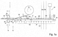
- FIGS. 1a, b, c the supply chain unit 44 is shown with a subsequent tubular bag assembly 1 :
- the supply chain 2 runs in a vertically standing circulating plane 2 ' , which the drawing plane of FIG. 3a is, between a downstream pulley 2 a and an upstream pulley 2 b, of which at least one is driven to set the supply chain in the desired manner in motion.
- the drivers 3 are widened in the rule and protrude laterally beyond the width of the slot 25 in order to push the products reliably forward, wherein on the support members 15 a, b also in the longitudinal direction 10 extending side guides 26 are arranged whose mutual distance is adapted as accurately as possible to the width of the products 100 , as well as the width - measured in the transverse direction 11 - the driver 3 is adapted to the width of the products 100 .
- FIG. 1a shows - and later on the basis of FIGS. 2a, b is explained in more detail - is the driver 3 the same Aufrechtwinkel 28, which he has taken during the main part of the conveyor line 23 to the horizontal plane, while diving around the pulley 2 a down around maintained until it is still in contact with the product 100 , Thus, until the upper edge of the contact surface 43 of the driver 3 is submerged below the level of the bearing surface for the products to avoid damaging the product.
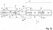
- FIG. 1b shows in plan view, pushes the subducting down follower 3 at the end of the conveying path 27 of the supply chain unit 44, the product 100 to a storage surface 29, which is fixedly mounted in the following tubular bag assembly and downstream of the supporting parts 15 a , b, preferably at the same level or slightly lower.
- FIGS. 2a, b and 3a-d show the design and function of the supply chain 2 , to which the drivers 3 are attached.
- FIG. 2a shows a part of the supply chain unit 44, namely the end of the conveying path 27 of the endless circulating supply chain 2 with a view of the orbital plane 2 '.
- the supply chain 2 - with this term should include all suitable conveying elements - is formed in this case as a toothed belt and the horizontally running upper strand 2.1 is deflected at the end of the conveying path 27 via a first guide roller 2 a in this case at right angles downwards and over an approximately further arranged further deflection roller 2 b in turn to return horizontally lower strand 2 '.
- the drivers 3 protrude in the orbital plane 2 ' from the supply chain 2 to the outside, and along the upper run 2' in this case vertically upwards.
- these drivers 3 are guided around the pulley 2 a at the end of the upper strand 2.1 in the direction 10 b, they would perform immovable attachment to the timing belt 2 with its forwardly directed contact surface 43 pivotal movement about the center of the guide roller 2 a, and so that the contact surface 43 in this area increasingly press with its upper edge against the back of the product 1 , and scraping down along this, which can damage the products 100 .
- the driver 3 are first of all formed on the supply chain 2 articulated about a pivot axis 7 extending in the transverse direction 11 .
- the driver 3 are formed in two parts with a base part 3 a, which is attached via the pivot axis 7 to the supply chain 2 and the driver part 3 b, which is wholly or predominantly above the support members 15 a, b and the base part 3 a is releasably attached.
- the driver part 3 b from above into the upper end face of the base part 3a can be inserted and latched - as in FIG. 2 b also shown in a separated state - by the driver part 3b has on its underside an insertion pin 6, which fits into a corresponding recess of the base part 3a, and between them is a detent device 36 is provided, for example, a known, pre-stressed by means of spring force detent ball, which optionally in the base part 3 a or in the driver part 3 b may be present and is biased by a spring force into a corresponding locking recess of the other part and engages.
- the base part 3 a is in the direction of the FIG. 2a and 2 B , So in side view of the orbital plane 2 'of the supply chain 2, the transverse direction 11, L-shaped with an upwardly, ie with respect to the circulating supply chain 2 to the outside, facing Einsteckschenkel 3 a 2, in which the receiving and locking device located for the driver part, and a thereto - preferably at the lower end - at an angle approximately in the direction of the supply chain 2 counter to the direction of travel 10 b extending guide leg 3 a first
- the driver 3, here the base part 3 a, may be arranged in a recess of the supply chain 2 , but is preferably viewed in the plan view of the side attached to this, as the supervision of Figure 2c shows.
- a slide guide 40 is arranged, the top and towards the end of the conveyor line an end face in the form of a guide curve 41 , from the top to the front end of the bottom in the form of an arc is convexly curved, arranged so that at the beginning of running around the pivot axis 7 of a driver 3 to this guide roller 2 a, first the lower edge and then the rear, preferably rounded, free end of the guide leg 3 a 1 is guided by the guide cam 41 so that the driver 3 maintains its angular position with respect to the pivot axis 7 - and thus the upright angle 28 is also maintained - to the top of the driver 3, here so the driver part 3 b, under the Level of the top of the support members 15 a, b is submerged and loses contact with the previously pushed down her product 100 .
- FIG. 2a Also shows, the support parts 15 a, b even before the end of the conveyor section 27 in the transport direction 10 b to the driver part 3b of the driver 3, which in accordance with FIG. 5b As a rule, wider than the slot 25, in which the driver 3 runs, can dive down.
- Each chain cheek 38 connects two such chain webs 39.
- Two middle, elastic latching arms 3.11 protrude in the middle of the longitudinal distance between the support arms 3.1 also from the central body down, spaced transversely about the width of a chain link 37.
- the locking arms 3.11 each have an inwardly directed cross -Rastnase 3.3 , which is directed towards the opposite transverse locking lug 3.3 and fits into a preferably formed in the outer chain cheek 38 formed detent opening and on the basis of the elastic bias of the locking arms 3.11 in this, wherein thereby the locking arms 3.11 laterally extend downwardly along the outer chain cheeks 38 .
- the contact surfaces of the contact arms 3.1 sit in this latched state on the two adjacent chain webs 39 .
- the contact surface 43 pointing in the direction of travel 10 b is curved backwards to avoid damaging the rear side of the product during the immersion under the contact surface.
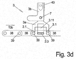
- FIG. 3 c is also shown as a with such locking arms, in this case the elastic locking arms 3.11, equipped driver 3 by a driver tool 21 b , which may be attached to a robot arm on the tool handle 20d , held not only, but the locking arms 3.11 as far as together can be pressed against each other that the Driver 3 between the chain cheeks 38 retracted from above and when releasing the pressing against each other outwards into the locking opening 42 engages.
- driver tool 21 b two on both sides of the driver downwardly projecting, with the angled and with the free end inwardly against the locking arms 3.11 directed gripper 35 have to longitudinally 10 extending joints controlled relative to the main part of the driver -Tool 21 b can be pivoted to grasp or release the driver 3 to the locking arms 3.11.
- the base parts 3 a usually in a significantly larger distance at the feed chain 2, in particular a toothed belt, provided to keep the production expense over the respectively required articulated connection about the pivot axis 7 of such a toothed belt low, at a Link chain - except for the presence of the locking openings 42 - requires no additional work.
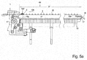
- FIGS. 4 and FIGS. 5a-c show, in an enlarged view, the supply chain unit 44 entirely or over only a part of its conveying path 27, via which products, here a product group 100 ', are conveyed in the direction of the tubular bag assembly 1 , which is a running support.
- Parts 15 a, b on both sides of the slot 25, through which the driver 3 project from the supply chain 2 below in the area above the support parts 15 a, b are formed.
- the support parts 15 a, b are divided in the direction 10 in individual support sections 16 , all of which are each attached to an endlessly circulating support chain 17 , of which one left and one right of the supply chain 2 is arranged, and each in a circulating plane 17 ' circulate in the FIGS. 5a , b drawn on the cover, which covers the circulation chain 17 .
- FIG. 5b and 5c for a relatively small product group 100 ' reveals, lies the product group 100' with its back to the driver 3 , which pushes them forward and lies with its bottom on both sides of the support members 15 a, b, so each one or more adjoining support -Sections 16, as in FIG. 5b and 5c recognizable, up.
- the circulating chain 17 is moved at the same speed in the direction 10 b as the supply chain 2 to relative movements between the bottom of the product or here the product group 100 and the top of the support parts 15 a, b, so the support portions 16 , to avoid.
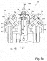
- FIG. 5c viewed in the longitudinal direction 10 b: It can be seen that the circumferential planes 17 'of the arranged on both sides of the supply chain 2 circulating chains 17 at an acute angle to the orbital plane 2' of the supply chain 2, symmetrical to the orbital plane 2 'of the supply chain 2, the same time the longitudinal center plane 10' the entire conveyor line is arranged.
- the support portions 16 arranged on these feed chains 17 when moved synchronously with the drivers 3 with the aid of the upper run of the feed chain 17 , have a horizontal support surface, ie upper surface, the support portions 16 protrude from the circulation chain 17 and its orbital plane 17 ' in one corresponding angle.
Landscapes
- Engineering & Computer Science (AREA)
- Mechanical Engineering (AREA)
Abstract
Um bei einer Zufuhrketten-Einheit schnelle Umrüstzeiten und dennoch ein schnelles, immer korrektes Füllen der Gefache der Zufuhrkette (2) zu ermöglichen, werden erfindungsgemäß - die Mitnehmer (3) an der Zufuhrkette lösbar (2) befestigt, und bei Bedarf gegen neue, anders gestaltete Mitnehmer (3) ersetzt, wodurch der Formatwechsel der Zufuhrketten-Einheit in extrem kurzer Zeit möglich wird und - eine mit der Zufuhrkette (2) mitlaufende Auflagefläche für die Produkte (100) so gestaltet, dass sie stromabwärtige Baugruppen für z.B. die Formung eines Folienschlauches möglichst wenig behindert.In order to enable fast changeover times in a supply chain unit and yet fast, always correct filling of the compartments of the supply chain (2), according to the invention - The driver (3) on the supply chain releasably attached (2), and replaced if necessary with new, differently shaped driver (3), whereby the format change of the supply chain unit in an extremely short time is possible, and a support surface for the products (100) running along with the supply chain (2) is designed to provide downstream components for e.g. the formation of a film tube impeded as little as possible.
Description
Die Erfindung betrifft eine Zufuhrketten-Einheit, wie sie insbesondere in Schlauchbeutelmaschinen zur definierten Zufuhr der zu verpackenden Produkte eingesetzt wird.The invention relates to a supply chain unit, as used in particular in tubular bag machines for the defined supply of the products to be packaged.
Bei Schlauchbeutelmaschinen werden Schlauchbeutel aus einer laufenden, zunächst ebenen, Folienbahn geformt, indem die Längsränder der - meist horizontal oder leicht schräg nach unter laufenden - Folienbahn gegeneinander gebogen und in Längsrichtung durchgehend gegeneinander versiegelt werden.In tubular bag machines, tubular bags are formed from a running, initially flat, film web by bending the longitudinal edges of the film web - usually horizontally or slightly obliquely downwards - against each other and sealing them longitudinally against each other.
Ins Innere des entstehenden Folienschlauches werden mit der gleichen Laufrichtung und meist auch der gleichen Laufgeschwindigkeit die Produkte von der Zufuhrketten-Einheit eingebracht, sodass sich die Produkte danach in den gewünschten Abständen innerhalb des Folienschlauches befinden, sodass nach dem Einbringen der Produkte der Folienschlauch durch Quersiegelnähte zwischen den Produkten in einzelne Schlauchbeutel unterteilt werden kann.Inside the resulting film tube are introduced with the same direction and usually the same running speed, the products of the supply chain unit, so that the products are then at the desired intervals within the film tube, so after inserting the products of the film tube by transverse sealing seams between the products can be divided into individual tubular bags.
Bei der Zufuhrketten-Einheit liegen die Produkte auf einer Auflagefläche auf und werden meist durch die in regelmäßigen Abständen an der Zufuhrkette befestigten Mitnehmer entlang der Auflagefläche vorwärts geschoben. Bei einer Schlauchbeutelmaschine muss die Zufuhrkette vor dem Punkt des Gegeneinander-Führens der Längsränder der Folienbahn aus dem inneren Querschnitt des entstehenden Folienschlauches herausgeführt werden, meist indem die Zufuhrkette nach unten abtaucht, wobei stromabwärts der Zufuhrketten-Einheit oft wenig Freiraum vorhanden ist.In the case of the supply chain unit, the products rest on a support surface and are usually pushed forward along the support surface by the carriers attached to the supply chain at regular intervals. In the case of a tubular bag machine, the feed chain has to be removed from the inner cross section of the resulting film tube before the point at which the longitudinal edges of the film web run against each other be led out, usually by the supply chain dives down, with downstream of the supply chain unit often little space is available.
Statt einer Zufuhrkette können jedoch auch andere Zufuhr-Förderer benutzt werden, weshalb für die Zwecke der vorliegenden Erfindung der eingeführte Begriff Zufuhrkette benutzt wird, dies jedoch jede Art von Zufuhr-Förderer sein kann, der geeignet ist, die Produkte in der notwendigen definierten Art und Weise in den entstehenden Folienschlauch hineinzuliefern, sei es ein Förderband, auf dessen ebener Oberseite die Produkte ohne Formschluss für den Weitertransport lediglich aufliegen, seien es Zahnriemen oder Gliederketten oder Ähnliches.However, instead of a feed chain, other feed conveyors may be used, for which reason the imported feed chain term is used for the purposes of the present invention, but this may be any type of feed conveyor capable of delivering the products in the necessary defined manner Way in the resulting film tube hineinzuliefern, be it a conveyor belt on the flat top of the products without form fit for further transport only rest, be it timing belt or link chains or the like.
Bei der Zufuhrketten-Einheit muss relativ oft ein sog. Formatwechsel durchgeführt werden, also die Umstellung von einem bisherigen auf ein neues abzupackendes Produkt, welches sich natürlich hinsichtlich Form, Gewicht, Größe und ggf. weiteren Parametern des Produktes in der Regel unterscheidet.In the supply chain unit, a so-called format change must be carried out relatively often, ie the changeover from a previous product to be packaged, which of course generally differs in terms of shape, weight, size and possibly further parameters of the product.
Denn dann müssen die Zufuhrketten umgerüstet werden, indem beispielsweise der Abstand der Mitnehmer in Längsrichtung entlang der Zufuhrkette verändert wird, ggf. die Mitnehmer auch körperlich anders gestaltet sein müssen in Anpassung an die Form des Produktes, und unter Umständen auch die Seitenführungen, die verhindern, dass das Produkt seitlich von der Zufuhrkette herunterläuft, in ihrem Abstand gegeneinander neu eingestellt werden.Because then the supply chains must be retrofitted, for example, by the distance of the driver is changed in the longitudinal direction along the feed chain, possibly the driver must also be physically different in adaptation to the shape of the product, and possibly the side guides that prevent that the product runs down the side of the feed chain, be readjusted in their distance from each other.
Bei den meisten Anwendungen ist hierfür der Ausbau der Zufuhrkette notwendig, was einen erheblichen Aufwand und eine lange Stillstandszeit der entsprechenden Maschine zur Folge hat.In most applications, this requires the removal of the supply chain, resulting in a considerable effort and a long downtime of the corresponding machine.
Es ist daher die Aufgabe gemäß der Erfindung, eine Zufuhrketten-Einheit zu schaffen, bei der mit geringem baulichen Aufwand immer die zuverlässige, korrekte Füllung der Zufuhrkette gewährleistet ist, ein Formatwechsel in sehr kurzer Zeit durchgeführt werden kann und die Zufuhrketten-Einheit stromabwärts möglichst wenig Freiraum beansprucht.It is therefore the object of the invention to provide a supply chain unit, in which the reliable, correct filling of the supply chain is guaranteed with little structural effort, a format change can be performed in a very short time and the supply chain unit downstream as little as possible Freiraum claimed.
Diese Aufgabe wird durch die Merkmale des Anspruchs 1 gelöst. Vorteilhafte Ausführungsformen ergeben sich aus den Unteransprüchen.This object is solved by the features of claim 1. Advantageous embodiments will be apparent from the dependent claims.
Um einen Formatwechsel an einer solchen Zufuhrketten-Einheit in möglichst kurzer Zeit durchzuführen, ist es bereits bekannt, die an der Zufuhrkette befestigten Mitnehmer oder die Nester für Produkte auswechselbar an der Zufuhrkette zu befestigen, um abhängig von Art und Größe des Produktes die Mitnehmer oder Nester in einem größeren oder kleineren Abstand auf der Zufuhrkette anzuordnen oder auch einfach anders geformte, an das neue Produkt angepasste, Mitnehmer oder Nester auf der Zufuhrkette zu befestigen.In order to perform a format change to such a supply chain unit in the shortest possible time, it is already known to attach the attached to the supply chain carrier or the nests for products replaceable on the supply chain, depending on the type and size of the product, the driver or nests to arrange on a larger or smaller distance on the supply chain or simply to attach differently shaped, adapted to the new product, driver or nests on the supply chain.
In der Regel läuft ja die Zufuhrkette endlos in einer vertikalen Umlaufebene um, wobei die Mitnehmer in dieser Umlaufebene radial nach außen abstehen.In general, yes, the feed chain runs endlessly in a vertical orbital plane, wherein the drivers protrude radially outward in this orbital plane.
Vom Obertrum einer solchen, über zwei horizontal beabstandete Umlaufrollen umlaufenden, Zufuhrkette ragen die Mitnehmer also nach oben ab. In Laufrichtung links und rechts dieser nach oben ragenden Mitnehmer verläuft in geringem Abstand jeweils ein Auflage-Teil einer Auflagefläche für die Produkte, wobei der ebenfalls in Laufrichtung verlaufende Schlitz zwischen den beiden Auflage-Teilen so gering wie möglich gewählt wird, also gerade groß genug, um die nach oben aufragenden Mitnehmer von der unter der Auflagefläche umlaufenden Zufuhrkette aus in den Bereich nach oberhalb der Auflagefläche aufragen zu lassen, und dort die Produkte vorwärts zu schieben.From the upper run of such, over two horizontally spaced circulating rollers encircling supply chain protrude so the carriers from above. In the direction of travel left and right of this upwardly projecting carrier runs at a small distance in each case a support part of a support surface for the products, wherein the also extending in the direction of slot between the two support parts is chosen as small as possible, so just big enough in order to allow the upwardly projecting carriers to rise from the supply chain circulating under the support surface into the area above the support surface, and to push the products there forwards.
Für die Formatumstellung muss also entweder der gesamte Mitnehmer leicht demontierbar und montierbar an der Zufuhrkette sein, oder der Mitnehmer besteht aus einem Basisteil, welches fest verbunden immer an der Zufuhrkette verbleibt und einem demgegenüber leicht montierbaren und demontierbaren Mitnehmer-Teil, welches an dem Basisteil zum Beispiel eingesteckt und verrastet oder auf andere Art und Weise sehr einfach gewechselt werden kann.For the format change so either the entire driver must be easy to dismantle and mount on the supply chain, or the driver consists of a base part, which always remains firmly attached to the supply chain and a contrast easily mountable and removable driver part, which on the base part for Example plugged and locked or can be easily changed in other ways.
Das Basisteil steht in diesem Fall in der Regel nicht über die Oberkante der Auflagefläche für die Produkte vor.The base part is in this case usually not on the upper edge of the support surface for the products before.
Bei bisherigen Lösungen musste zum Wechseln der Mitnehmer die Zufuhrkette entweder komplett aus der Schlauchbeutel-Maschine ausgebaut und dann die Mitnehmer gewechselt werden oder es mussten zumindest andere Teile der Schlauchbeutel-Maschine, wie Abdeckungen, Gehäuseteile u.ä. demontiert werden, um die Mitnehmer an der dann besser zugänglichen Zufuhrkette wechseln zu können.In previous solutions had to change the driver, the supply chain either completely removed from the tubular bag machine and then the drivers are changed or at least had other parts of the tubular bag machine, such as covers, housing parts u.ä. be dismantled in order to change the carriers on the then more accessible supply chain.
Erfindungsgemäß sind die Mitnehmer und insbesondere deren Befestigung gegenüber der Zufuhrkette so ausgebildet, dass entweder zum Lösen des gesamten Mitnehmers von der Zufuhrkette oder wenigstens eines Teiles, insbesondere des Mitnehmerteils vom Basis-Teil des Mitnehmers, keinerlei Demontagearbeiten an der Schlauchbeutel-Maschine - außer den demontierten Mitnehmern - durchgeführt werden müssen. Vorzugsweise werden die Mitnehmer oder Teile des Mitnehmers in der Umlaufebene nach außen, beim Obertrum also nach oben, abgezogen und/oder auf gesteckt.According to the invention, the drivers and in particular their attachment relative to the supply chain are designed so that either to disengage the entire driver of the supply chain or at least a part, in particular of the driver part of the base part of the driver, no disassembly work on the tubular bag machine - except the dismantled Carrier - must be carried out. Preferably, the drivers or parts of the driver in the circulation plane to the outside, the top strand so up, deducted and / or put on.
Wenn im Folgenden davon gesprochen wird, dass zwei Teile aneinander entweder leicht lösbar oder nicht lösbar befestigt sind, so ist dies so zu verstehen, dass - "nicht lösbar" bedeuten soll, dass die beiden Teile entweder nur unter Zerstörung der Verbindung zwischen ihnen voneinander gelöst werden können oder mittels zeitaufwändiger Demontagearbeiten, die insbesondere mehr als 10 Sekunden benötigen, insbesondere unter Benutzung von Werkzeugen und - "leicht lösbar" bedeuten soll, dass die beiden Teile mit sehr geringem Zeitaufwand, die insbesondere weniger als 10 Sekunden benötigen, insbesondere ohne Benutzung eines Werkzeuges, voneinander ohne Zerstörung des Verbindungsmechanismus gelöst werden können, insbesondere durch ineinanderstecken oder ineinanderschieben und/oder Verrasten, und dadurch bereits die Verbindung hergestellt istWhen it is said in the following that two parts are attached to each other either easily detachable or non-detachable, so it should be understood that - "not solvable" to mean that the two parts either dissolved only by destroying the connection between them or by means of time-consuming dismantling work, which in particular require more than 10 seconds, in particular using tools and - "easily detachable" means that the two parts can be solved with very little time, in particular less than 10 seconds, in particular without using a tool from each other without destroying the connection mechanism, in particular by nesting or telescoping and / or locking, and thereby already the connection is made
In einer ersten Bauform der Mitnehmer bestehen diese aus Basisteil und daran leicht lösbar befestigtem Mitnehmerteil, wobei das Mitnehmerteil am Basisteil befestigt wird z.B. durch einfaches Einstecken und dabei Verrasten der beiden Teile gegeneinander, und umgekehrt durch einfaches Abziehen des Mitnehmerteils nach oben dieses demontiert werden kann.In a first design of the driver, these consist of base part and thereon easily releasably attached driver part, wherein the driver part is attached to the base part, e.g. by simply plugging and thereby locking the two parts against each other, and vice versa by simply pulling the driver upwards this can be dismantled.
Dabei besteht das Problem, dass die Mitnehmer am Ende der Förderstrecke der Zufuhrkette, also wenn der Mitnehmer um die vordere Umlenkrolle herum geführt wird, nicht radial von der Umlenkrolle abstehen soll, sondern der entlang der Förderstrecke immer im gleichen Aufrecht-Winkel zur Horizontalen nach oben aufragende Mitnehmer diesen Aufrecht-Winkel auch zu Beginn des Umlaufs um die stromabwärtige Umlenkrolle so lange beibehalten soll, bis die Oberkante des Mitnehmers unter die Oberkante der Auflagefläche der Zufuhrkette oder eine stromabwärtige nachgeordnete, weitere Auflagefläche, auf die die Produkte von der Zufuhrkette aufgeschoben werden, abgetaucht ist.In this case, there is the problem that the driver at the end of the conveying path of the supply chain, so when the driver is guided around the front guide roller, should not protrude radially from the guide roller, but along the conveyor line always at the same upright angle to the horizontal upwards upstanding drivers should maintain this upright angle even at the beginning of the circulation around the downstream pulley until the upper edge of the driver under the upper edge of the support surface of the feed chain or a downstream downstream, further bearing surface on which the products are pushed by the supply chain, has submerged.
Zu diesem Zweck müssen die Mitnehmer vorzugsweise gelenkig um eine in Querrichtung verlaufende Schwenkachse innerhalb des Mitnehmers oder gegenüber der Zufuhrkette gestaltet sein und mit einer entsprechenden Kulissenführung im Bereich des beginnenden Herumführens um die Umlenkrolle geführt sein.For this purpose, the drivers must preferably be articulated about a transverse pivot axis within the driver or against the supply chain and be guided with a corresponding slotted guide in the area of incipient guiding around the pulley.
Beispielsweise kann der der Zufuhrkette zugewandte Teil des einstückigen Mitnehmers oder das Basisteil eines zweiteiligen Mitnehmers einen in Laufrichtung der Zufuhrkette sich erstreckenden Führungs-Schenkel aufweisen - beispielsweise neben der eigentlichen Zufuhrkette - der am Ende der Transportstrecke formschlüssig mit einer darunter angeordneten Führungs-Schiene zusammenwirkt, indem die Führungs-Schiene den Führungs-Schenkel beim Erreichen und Umlaufen des Mitnehmers um die stromabwärtige Umlenkrolle solange aufrecht hält, bis der Mitnehmer außer Kontakt mit dem von ihm entlang der Auflagefläche vorwärts geschobenen Produkt gerät.For example, the supply chain facing part of the one-piece driver or the base part of a two-piece driver in the running direction of the supply chain extending guide leg - for example, next to the actual supply chain - which cooperates positively at the end of the transport path with an underlying guide rail, in that the guide rail holds the guide leg upright as the driver moves around the downstream guide pulley until the driver comes out of contact with the product pushed forward along the support surface.
Bei einer zweiten Bauform, ist der - dann vorzugsweise auch einstückige - Mitnehmer im Ganzen leicht lösbar an der Zufuhrkette befestigt, wobei in der Regel eine gelenkige Befestigung zwischen Zufuhrkette und Mitnehmer nicht möglich.In a second design, the - then preferably one-piece - driver as a whole is easily releasably attached to the supply chain, usually an articulated attachment between supply chain and driver not possible.
Der Mitnehmer kann dann ersatzweise aus gelenkig, aber nicht lösbar, miteinander verbundenem Basisteil und darauf befestigtem Mitnehmerteil bestehen, die für den Formatwechsel nicht voneinander getrennt werden, sondern in der Regel nur unter Zerstörung voneinander getrennt werden können. Dabei wird das Basisteil allerdings nicht gelenkig an der Zufuhrkette befestigt, sondern das Mitnehmerteil ist um die Querachse zum Basisteil beweglich, um in der zuvor beschriebenen Weise seinen Aufrecht-Winkel auch im Bereich des ersten Teils des Umlaufes um die stromabwärtige Umlenkrolle beizubehalten.The driver can then substitute articulated, but not detachable, interconnected base part and attached driver part exist, which are not separated from each other for the format change, but can be separated from each other usually only with destruction. However, the base part is not hinged to the supply chain, but the driver is movable about the transverse axis to the base to maintain its upright angle in the manner described above in the region of the first part of the circulation around the downstream pulley.
In diesem Fall müssen die zuvor zwischen dem Mitnehmer und einer entsprechenden feststehenden Führungsschiene beschriebenen Ausgestaltungen zwischen dem Mitnehmer-Teil und einer entsprechenden feststehenden Führungsschiene vorhanden sein.In this case, the previously described between the driver and a corresponding fixed guide rail configurations between the driver part and a corresponding fixed guide rail must be present.
Auch bei der zuvor beschriebene Lösung eines von einem Basisteil leicht demontierbaren Mitnehmerteils kann entweder die Verbindung zwischen diesen beiden Teilen eine solche quer verlaufende Schwenkachse aufweisen oder innerhalb des demontierbaren Mitnehmerteiles, in dem dieses selbst wieder aus zwei gelenkig miteinander verbundenen Einzelteilen besteht, die zueinander um die besagte Querachse verschwenkbar sind, in der Regel jedoch nicht ohne Zerstörung demontierbar sind.Also in the solution described above one of a base part easily removable driver part either the connection between these two parts may have such a transverse pivot axis or within the removable driver part in which this itself consists of two articulated interconnected items that each other to the said transverse axis are pivotable, but usually can not be dismantled without destruction.
Wenn bei zweiteiligen Mitnehmern das Basisteil immer an der Zufuhrkette verbleibt, können die Abstände zwischen den Mitnehmern nur dadurch verändert werden, indem das Mitnehmerteil entweder auf jedem oder nur jedem zweiten oder nur jedem dritten Basisteil aufgesetzt wird, sodass die mögliche entstehende Größe der Gefache immer ein ganzzahliges Vielfaches - hinsichtlich der Länge in Durchlaufrichtung - des kürzesten möglichen Gefaches sein kann.If, in the case of two-part carriers, the base part always remains on the supply chain, the distances between the carriers can only be changed as a result be placed by the driver part either on every or every other or only every third base part, so that the possible resulting size of the compartments can always be an integer multiple - in terms of length in the direction of passage - the shortest possible Gefaches.
Will man sehr variabel sein, müssten hier also sehr viele Basisteile in sehr geringem Abstand an der Zufuhrkette befestigt werden.If you want to be very variable, so many base parts would have to be attached to the supply chain at a very short distance.
Wenn dagegen zum Wechseln des Formates immer der gesamte Mitnehmer von der Zufuhrkette entfernt wird, müssen lediglich in Längsrichtung eng beabstandete Befestigungsvorrichtungen an der Zufuhrkette hierfür vorhanden sein.On the other hand, if the entire carrier is always removed from the supply chain to change the format, only fastening devices which are closely spaced in the longitudinal direction need be present on the supply chain for this purpose.
Eine Möglichkeit der Zufuhrkette hierfür - statt zum Beispiel eines Zahnriemens oder glatten Riemens - ist eine aus gelenkig um Querachsen miteinander verbundenen Kettengliedern bestehende übliche Gliederkette als Zufuhrkette. Der übliche konstruktive Aufbau einer solchen mehrgliedrigen Kette mit insbesondere zwei Seitenwangen ermöglicht es, in jedes einzelne Kettenglied und die dabei sich immer im gleichen Abstand befindenden Ketten-Stege jeweils einen Mitnehmer einzustecken, was eine optimal geringe Teilung der Mitnehmer entlang der Gliederkette ergibt.One possibility of the supply chain for this purpose - instead of, for example, a toothed belt or smooth belt - is an existing from articulated about transverse axes chain links existing chain links as a supply chain. The usual structural design of such a multi-link chain with in particular two side cheeks makes it possible to insert a driver into each individual chain link and thereby always at the same distance chain webs, resulting in an optimally low pitch of the driver along the link chain.
Eine solche Befestigung führt dann jedoch in der Regel nicht zu einer Schwenkbarkeit des Mitnehmers direkt gegenüber der Zufuhrkette, sondern diese Verschwenkbarkeit muss in einem im Mitnehmer selbst vorhandenen Gelenk realisiert sein.However, such attachment usually does not lead to a pivoting of the driver directly opposite the supply chain, but this pivotability must be realized in a self-existing in the driver joint.
Bei Zufuhrketten-Einheiten gibt es häufig das Problem, dass ein mit seiner Unterseite auf einer feststehenden Auflagefläche der Zufuhrketten-Einheit entlang geschobenes Produkt nicht akzeptabel ist, beispielsweise wenn es sich um Kekse handelt, die auf der Unterseite eine Beschichtung aus Schokolade besitzen, da sich diese auf der Auflagefläche ablagern und diese verschmutzen und zusätzlich die Produkte verunstalten würde.In the case of feed chain units, there is often the problem that a product pushed along with its underside on a fixed support surface of the feed chain unit is unacceptable, for example, when it comes to biscuits having a coating of chocolate on the underside, since depositing them on the support surface and soiling them and additionally spoiling the products.
In diesem Fall besteht eine Lösung darin, die Auflagefläche der Zufuhrketten-Einheit mit der Zufuhrkette in Laufrichtung mitlaufen zu lassen, indem die links und rechts der Mitnehmer vorhandenen Auflageflächen-Teile zum einen in Laufrichtung angetrieben sind und zum anderen in der Regel aus mehreren, in Laufrichtung aufeinander folgenden, Auflage-Abschnitten bestehen.In this case, one solution is to run along the bearing surface of the feed chain unit with the supply chain in the direction in which the left and right of the driver existing bearing surface parts are driven to one in the running direction and on the other usually several, in Running direction consecutive, circulation sections exist.
Dann erfolgt - da die Laufgeschwindigkeit der Auflagefläche derjenigen der Transportkette entspricht - keine Relativbewegung in Längsrichtung zwischen Produkt und Auflagefläche - und die beschriebenen Nachteile werden vermieden.Then takes place - since the running speed of the support surface of those of the transport chain corresponds - no relative movement in the longitudinal direction between the product and the support surface - and the disadvantages described are avoided.
Um die Bewegung der mitlaufenden Auflageflächen-Teile mit der Zufuhrkette zu bewirken, können die Auflageflächen-Teile links und rechts von den Mitnehmern direkt an der Zufuhrkette befestigt werden und mittels dieser bewegt werden. Dies würde allerdings zum einen speziell bei einer Schlauchbeutel-Maschine das Wechseln der Mitnehmer an der Zufuhrkette zusätzlich behindern, vor allem aber muss ja am Ende der Förderstrecke die Zufuhrkette nach unten abtauchen, und zuvor noch das Produkt auf eine stromabwärts vorhandene, in der Regel stillstehende, Ablage-Fläche schieben.In order to effect the movement of the follower bearing surface parts with the supply chain, the support surface parts can be attached to the left and right of the drivers directly to the supply chain and moved by this. However, this would on the one hand especially in a tubular bag machine interfere with the changing of the driver on the supply chain, but above all, must indeed dive down the supply chain at the end of the conveyor line, and previously the product to a downstream, usually stationary , Slide shelf.
Dadurch kann die von oben herangeführte Folienbahn mit ihren Seitenkanten um das auf dieser Ablage-Fläche liegende Produkt herum nach unten geführt und dort gegeneinander gelegt und mit einer Längssiegelnaht gegeneinander versiegelt werden.As a result, the film web brought up from above can be guided with its side edges around the product lying on this storage surface downwards and placed there against each other and sealed against each other with a longitudinal sealing seam.
Um hierfür möglichst weit stromaufwärts ausreichend Platz zu schaffen, werden die Auflageflächen-Teile, insbesondere die diese bildenden einzelnen Auflageabschnitte, erfindungsgemäß vorzugsweise mittels je einer ebenfalls endlos umlaufenden Auflage-Kette bewegt, an der die einzelnen Abschnitte befestigt sind und von denen sich je eine Auflage-Kette links und rechts der Zufuhrkette befindet.To this end as far as possible to create sufficient space, the support surface parts, in particular the individual support sections forming this, according to the invention preferably by means of a likewise endless circulating support chain moves to which the individual sections are attached and of which each have a support Chain located to the left and right of the feed chain.
Jedoch sind dabei die Umlaufebenen der beiden Auflageketten in Laufrichtung betrachtet im Winkel zur Umlaufebene der Zufuhrkette angeordnet, indem sich dasHowever, the circulation levels of the two support chains are viewed in the direction of rotation at an angle to the orbital plane of the supply chain arranged by the
Obertrum der Auflagekette näher an der Umlaufebene der Zufuhrkette befindet als das Untertrum.Upper strand of the support chain is closer to the orbital plane of the supply chain than the lower strand.
Die Auflage-Abschnitte ragen dabei nicht im rechten Winkel von der Umlaufebene der Auflagekette ab, sondern in einem solchen Winkel, dass sie bei Bewegung entlang des Obertrums eine mit den Abschnitten der anderen Auflagekette fluchtende, in der Regel horizontale, Ebene bilden.The support sections do not protrude at a right angle from the orbital plane of the support chain, but at such an angle that when moving along the upper strand they form an aligned, usually horizontal, plane with the sections of the other support chain.
Der Vorteil dieser Anordnung besteht darin, dass die Auflageabschnitte beim Erreichen ihrer stromabwärtigen Umlenkrolle ihrer Auflagekette nicht nur nach unten abtauchen, sondern gleichzeitig auch mit ihrem freien Ende von der vertikalen Längsmittelebene der Zufuhrkette und insbesondere der gesamten Schlauchbeutelmaschine nach außen wegschwenken, und damit sehr früh sehr viel Raum für das nach unten und gegeneinander Führen der Längsseitenkanten der Folienbahn freigegeben wird.The advantage of this arrangement is that the support sections not only dive down when reaching their downstream pulley their support chain down, but at the same time swing away with its free end of the vertical longitudinal center plane of the feed chain and in particular the entire bag machine outside, and very early very a lot of space for the down and against each other guiding the longitudinal side edges of the film web is released.
Ausführungsformen gemäß der Erfindung sind im Folgenden beispielhaft näher beschrieben. Es zeigen:
- Fig. 1a,b,c:
- die Zufuhrketten-Einheit in Seitenansicht, Aufsicht und Frontansicht,
- Fig. 2a, b:
- die Zufuhrkette der Zufuhrketten-Einheit in unterschiedlichen Vergrößerungen ausschnittweise in der Seitenansicht,
- Fig. 2c:
- die Führung der Mitnehmer in der Aufsicht,
- Fig. 3a - d:
- eine zweite Bauform einer Zufuhrkette in Seitenansicht, Aufsicht und Frontansicht,
- Fig. 4:
- den Endbereich der Zufuhrketten-Einheit gemäß
Figur 1 in perspektivischer Ansicht, - Fig. 5a, b, c:
- die Förderstrecke der Zufuhrketten-Einheit mit Zufuhrkette und Auflagefläche gemäß
Figur 1 in Seitenansicht, Aufsicht und Frontansicht.
- Fig. 1 a, b, c:
- the supply chain unit in side view, top view and front view,
- 2 a, b:
- the supply chain of the supply chain unit in different magnifications partially in the side view,
- Figure 2 c.:
- the leadership of the drivers in the supervision,
- 3 a - d:
- a second design of a supply chain in side view, top view and front view,
- 4 :
- the end portion of the feed chain unit according to
FIG. 1 in perspective view, - 5 a, b, c:
- the conveying path of the supply chain unit with supply chain and bearing surface according to
FIG. 1 in side view, top view and front view.
In den
Die Zufuhrkette 2 läuft in einer vertikal stehenden Umlaufebene 2' um, welche die Zeichenebene der
Betrachtet quer zu dieser Umlaufebene 2' wie in
Oberhalb des Schlitzes 25 sind die Mitnehmer 3 in der Regel verbreitert und ragen seitlich über die Breite des Schlitzes 25 hinaus, um die Produkte zuverlässig vorwärts schieben zu können, wobei an den Auflageteilen 15a, b ebenfalls in Längsrichtung 10 verlaufend Seitenführungen 26 angeordnet sind, deren gegenseitiger Abstand möglichst genau an die Breite der Produkte 100 angepasst ist, ebenso wie auch die Breite - in Querrichtung 11 gemessen - der Mitnehmer 3 an die Breite der Produkte 100 angepasst ist.Above the
Im normalen Betrieb der z.B. Schlauchbeutelmaschine ist es von essentieller Bedeutung, dass in jedes der - zwischen den in Längsrichtung 10 beabstandeten Mitnehmern 3 gebildeten - Gefache 4 der Zufuhrkette 2 jeweils meist nur ein Produkt 100 eingelegt ist, sodass die Darstellung in
Gegen Ende der Förderstrecke 27 der Zufuhrkette 2, also der Strecke, über die sich die Mitnehmer 3 der Zufuhrkette 2 bewegen können, tauchen die Mitnehmer 3 durch das Herumführen um die stromabwärtige Umlenkrolle 2a nach unten weg und verlieren dadurch den Kontakt zu dem vor ihm hergeschobenen Produkt 100. Towards the end of the
Wie
Wie am besten
Die Funktion der nachfolgend dargestellten Schlauchbeutel-Baugruppe 1 mit der Längs-Siegeleinheit 1a und der Quer-Siegeleinheit 1b ist für die vorliegende Erfindung nicht relevant.The function of the tubular bag assembly 1 shown below with the
Die
Die
Die Zufuhrkette 2 - mit diesem Begriff sollen alle geeigneten Förderelemente umfasst sein - ist in diesem Fall als Zahnriemen ausgebildet und das horizontal laufende Obertrum 2.1 wird am Ende der Förderstrecke 27 über eine erste Umlenkrolle 2a in diesem Fall im rechten Winkel nach unten umgelenkt und über eine etwa darunter angeordnete weitere Umlenkrolle 2b in zum wiederum horizontal zurücklaufenden Untertrum 2'. The supply chain 2 - with this term should include all suitable conveying elements - is formed in this case as a toothed belt and the horizontally running upper strand 2.1 is deflected at the end of the conveying
Die Mitnehmer 3 ragen in der Umlaufebene 2' von der Zufuhrkette 2 nach außen ab, und entlang des Obertrums 2' in diesem Fall senkrecht nach oben.The
Sie erstrecken sich dabei durch einen am besten in Figur 7b sichtbaren Schlitz 25, der in Längsrichtung 10b verlaufend zwischen den seitlich davon angeordneten Auflageteilen 15a, b gebildet wird, bis über die Oberseite der Auflageflächen 15a, b hinaus und können dadurch die im Bereich darüber in Querrichtung 11 über den Schlitz 25 hinweg auf den Auflageteilen 15a, b liegende Produkt vorwärts schieben, in diesem Fall nach links.They extend through a best visible in
Wenn diese Mitnehmer 3 um die Umlenkrolle 2a am Ende des Obertrums 2.1 in Laufrichtung 10b herumgeführt werden, würden sie bei unbeweglicher Befestigung am Zahnriemen 2 mit ihrer in Laufrichtung nach vorn gerichteten Kontaktfläche 43 eine Schwenkbewegung um den Mittelpunkt der Umlenkrolle 2a vollziehen, und damit die Kontaktfläche 43 in diesem Bereich zunehmend mit ihrer Oberkante gegen die Rückseite des Produktes 1 drücken, und an diesem entlang nach unten schaben, was die Produkte 100 beschädigen kann.If these
Um zu erreichen, dass die beim Umlaufen um diese Umlenkrolle 2a nach unten abtauchenden Mitnehmer 3 bis zum Abtauchen unterhalb der Höhe der Auflage-Teile 15a, b ihren Aufrechtwinkel 28 zwischen der Kontaktfläche 43 und der Horizontalen beibehalten, sind die Mitnehmer 3 zunächst einmal an der Zufuhrkette 2 gelenkig um eine in Querrichtung 11 verlaufende Schwenkachse 7 ausgebildet. Um Größe und Form der Kontaktfläche 43 je nach zu handhabendem Produkt 100 anpassen zu können, sind die Mitnehmer 3 zweiteilig ausgebildet mit einem Basisteil 3a, welches über die Schwenkachse 7 an der Zufuhrkette 2 befestigt ist und das Mitnehmerteil 3b, welches sich ganz oder überwiegend oberhalb der Auflageteile 15a, b befindet und am Basisteil 3a lösbar befestigt ist.In order to achieve that when driving around this
In diesem Fall ist das Mitnehmerteil 3b von oben in die obere Stirnfläche des Basisteiles 3a einsteckbar und verrastbar - wie in
Das Basisteil 3a ist in der Blickrichtung der
Der Mitnehmer 3, hier das Basisteil 3a, kann in einer Aussparung der Zufuhrkette 2 angeordnet sein, ist jedoch vorzugsweise in der Aufsicht betrachtet seitlich an dieser befestigt, wie die Aufsicht der
Gegen Ende der Förderstrecke 27 ist auf Höhe der Unterkante des Führungsschenkels 3a1 eine Kulissenführung 40 angeordnet, deren Oberseite und in Richtung Ende der Förderstrecke eine Stirnfläche in Form einer Führungskurve 41, die von der Oberseite zum am vorderen Ende der Unterseite in Form eines Bogens konvex gekrümmt ist, so angeordnet, dass zu Beginn des Herumlaufens der Schwenkachse 7 eines Mitnehmers 3 um diese Umlenkrolle 2a, zunächst die Unterkante und dann die hintere, vorzugsweise gerundete, freie Ende des Führungsschenkels 3a1 durch die Führungskurve 41 so geführt wird, dass der Mitnehmer 3 seine Winkelstellung bezüglich der Schwenkachse 7 beibehält - und damit der Aufrecht-Winkel 28 ebenfalls beibehalten wird - bis die Oberkante des Mitnehmers 3, hier also des Mitnehmerteiles 3b, unter das Niveau der Oberseite der Auflageteile 15a, b abgetaucht ist und den Kontakt mit dem bisher vor sich her geschobenen Produkt 100 verliert.Towards the end of the
Dadurch sind Beschädigungen an der Rückseite des Produktes 100 durch das Mitnehmerteil 3b vermieden.As a result, damage to the back of the
Wie
Stromabwärts hinter dem Ende der Auflageteile 15a, b befindet sich auf gleichem oder geringfügig niedrigerem Niveau die stillstehende Auflagefläche 29, auf welche das Produkt 100 vom Mitnehmer 3 am Ende der Förderstrecke 27 aufgeschoben wird, bevor der Mitnehmer 3 den Kontakt zum Produkt 100 verliert, um von dort mit Hilfe der an ihm anliegenden, in
Die
- Eine solche Gliederkette besteht aus in
Längsrichtung 10 beabstandeten, quer verlaufenden,zylindrischen Kettenstegen 39, an deren linken und rechten Ende jeweils eine äußere und eine innere Kettenwange 38 angreifen, wobei die innere oder die äußere, meist die äußere,Kettenwange 38 verschwenkbar um die Querachse des Kettensteges 39 ist.
- Such a link chain consists of longitudinally spaced 10 , transversely extending,
cylindrical chain webs 39 , at the left and right end in each case an outer and aninner chain cheek 38 attack, the inner or the outer, usually the outer,chain cheek 38 pivotable about the transverse axis of thechain web 39 is.
Jede Kettenwange 38 verbindet zwei solcher Kettenstege 39. Each
An einer solchen Gliederkette können spezifisch gestaltete Mitnehmer 3 von oben aufgesteckt und verrastet werden wie am besten in
- Von dem Zentralkörper des
Mitnehmers 3 ragen Anlagearme 3.1 nach unten, die inLängsrichtung 10 beabstandet sind, mit einem solchen Längs-Abstand, dass sie mit ihren freien stirnseitigen Anlageflächen gerade auf je einem von zwei benachbarten Kettenstegen 39 aufliegen können, ohne beim Herumlaufen der Kette um ein Zahnrad mit dem Zahnrad zu kollidieren.
- Of the central body of the
driver 3 contact arms 3.1 project downwards, which are spaced in thelongitudinal direction 10 , with such a longitudinal distance that they can rest with their free end-side contact surfaces straight on each one of twoadjacent chain webs 39 , without running around the chain to collide a gear with the gear.
Zwei mittlere, elastische Rastarme 3.11 ragen in der Mitte des Längs-Abstandes zwischen den Anlagearme 3.1 ebenfalls von dem Zentralkörper nach unten, in Querrichtung beabstandet etwa um die Breite eines Kettengliedes 37. An ihrem unteren Ende weisen die Rastarme 3.11 jeweils eine nach innen gerichtete Quer-Rastnase 3.3 auf, die in Richtung der gegenüberliegen Quer-Rastnase 3.3 gerichtet ist und in eine in der vorzugsweise außen liegenden Kettenwange 38 ausgebildete Rastöffnung passt und auf Grund der elastischen Vorspannung der Rastarme 3.11 auch in diesen verrrastet, wobei sich dabei die Rastarme 3.11 seitlich außen entlang der äußeren Kettenwangen 38 nach unten erstrecken.Two middle, elastic latching arms 3.11 protrude in the middle of the longitudinal distance between the support arms 3.1 also from the central body down, spaced transversely about the width of a
Die Anlageflächen der Anlagearme 3.1 sitzen in diesem verrasteten Zustand auf den zwei benachbarten Kettenstegen 39 auf.The contact surfaces of the contact arms 3.1 sit in this latched state on the two
Am oberen Ende dieses vorzugsweise einstückigen Mitnehmers 3 ist die in Laufrichtung 10b weisende Kontaktfläche 43 nach hinten fliehend gekrümmt, um beim Abtauchen unter die Auflagefläche die Rückseite des Produktes nicht zu beschädigen.At the upper end of this preferably one-
In
Zu diesem Zweck kann ein solches Mitnehmer-Werkzeug 21b zwei beidseits des Mitnehmers nach unten ragende, mit dem gewinkeltem und mit dem freien Ende nach innen gegen die Rastarme 3.11 gerichteten Greifer 35 besitzen, um in Längsrichtung 10 verlaufende Gelenke gesteuert gegenüber dem Hauptteil des Mitnehmer-Werkzeuges 21b verschwenkt werden können zum Ergreifen oder Loslassen des Mitnehmers 3 an den Rastarmen 3.11. For this purpose, such a
Der Vorteil dieser Ausführungsform einer Zufuhrkette als Gliederkette und andererseits der dargestellten oder einer ähnlich wirkenden Form von Mitnehmern 3 besteht darin, dass Mitnehmer an jedem Kettenglied - sofern an jedem Kettenglied 37 die entsprechende Rastöffnung 42 vorhanden ist - eingesetzt werden kann, also ein sehr geringer Minimalabstand zwischen den Mitnehmern zur Verfügung steht, und größere Abstände immer ein ganzzahliges Mehrfaches davon sind.The advantage of this embodiment of a supply chain as a link chain and on the other hand the illustrated or a similarly acting form of
Bei der Ausführungsform gemäß
Der Nachteil der in den
Um die Beibehaltung des Aufrechtwinkels 28 beim Abtauchen des Mitnehmers unter das vorwärts geschobene Produkt am Ende der Förderstrecke zu ermöglichen - falls dies aufgrund des Produktes notwendig ist - weist ein solcher Mitnehmer 3 in einer weiteren Ausführungsform - wie in
Daran ist - nach oben aufragend - ein Mitnehmer-Teil 3b um eine quer verlaufende Schwenkachse 7 verschwenkbar befestigt, welches insbesondere gestaltet ist wie in Figur 4 b und in gleicher Weise mit einer Führungsschiene zusammenwirken kann, um die Beibehaltung des Aufrechtwinkels 28 beim Abtauchen des Mitnehmers 3 zu ermöglichen. Beim Wechseln des Mitnehmers wird dieser also hier im Ganzen von der Gliederkette demontiert.This is - upstanding - a
Aussehen und Zusammenwirken des Mitnehmerteiles 3b mit einer Kulissenführung 40 können dann genauso gelöst werden wie anhand der
Die
Dabei sind die Auflage-Teile 15a, b in Laufrichtung 10 unterteilt in einzelne Auflage-Abschnitte 16, die allesamt jeweils an einer endlos umlaufenden Auflagekette 17 befestigt sind, von denen eine links und eine rechts der Zufuhrkette 2 angeordnet ist, und die jeweils in einer Umlaufebene 17' umlaufen, in den
Wie
Deshalb wird in aller Regel die Umlaufkette 17 mit der gleichen Geschwindigkeit in Laufrichtung 10b bewegt wie die Zufuhrkette 2, um Relativbewegungen zwischen der Unterseite des Produktes oder hier der Produktgruppe 100 und der Oberseite der Auflage-Teile 15a,b, also der Auflageabschnitte 16, zu vermeiden.Therefore, as a rule, the circulating
Das wesentliche der Ausbildung dieser Förderstrecke zeigt
Damit die an diesen Zufuhrketten 17 angeordneten Auflageabschnitte 16, wenn sie mit Hilfe des Obertrums der Zufuhrkette 17 synchron mit den Mitnehmern 3 bewegt werden, eine horizontale Auflagefläche, also Oberseite besitzen, ragen die Auflageabschnitte 16 von der Umlaufkette 17 und deren Umlaufebene 17' in einem entsprechenden Winkel ab.In order that the
Der Zweck dieser Anordnung ist am besten in
Sobald die Abschnitte 16 amEnde der Förderstrecke 27 in den Bereich der dortigen Umlenkrolle 19a gelangen, werden sie nicht nur radial nach außen geschwenkt, sondern gleichzeitig aufgrund der Schrägstellung der Umlaufebene 17' auch nach unten bewegt, sodass auf dem Höhenniveau der Auflageteile 15a, b amEnde der Förderstrecke 27 unmittelbar nachgeordnet Raum für den Beginn der Schlauchbeutel-Baugruppe 1 besteht.
- Once the
sections 16 at the end of theconveyor line 27 in the region of thelocal pulley 19 a, they are not only pivoted radially outward, but also moved due to the inclination of the orbital plane 17 ' down, so that at the height level of thesupport members 15 a , B at the end of theconveyor section 27 immediately downstream space for the beginning of the tubular bag assembly 1 is.
Diese weist bei der in den
- 11
- Schlauchbeutel-BaugruppeTubular bag assembly
- 1a 1 a
- Längssiegel-EinheitLongitudinal sealing unit
- 1b 1 b
- Quersiegel-EinheitTransverse sealing unit
- 22
- Zufuhrkettesupply chain
- 2.12.1
- Obertrumobertrum
- 2.22.2
- Untertrumstrand
- 2a, b 2 a, b
- Umlenkrolleidler pulley
- 2'2 '
- Umlaufebeneorbital plane
- 33
- Mitnehmertakeaway
- 3a 3 a
- Basisteilbase
- 3b 3 b
- Mitnehmerteildriver part
- 3a1 3 a 1
- Führungsschenkelguide leg
- 3a2 3 a 2
- Einsteckschenkelinsert leg
- 3.13.1
- Rastarmdetent arm
- 3.23.2
- Längs-RastnaseLongitudinal locking lug
- 3.33.3
- Quer-RastnaseCross-locking lug
- 44
- GefachGefach
- 55
- Produkt-AuflageProduct Edition
- 66
- Einsteckzapfeninsertion pin
- 77
- Schwenkachseswivel axis
- 88th
- Produktbandproduct band
- 99
- Längsabstandlongitudinal distance
- 10a, b 10 a, b
- Längsrichtung, DurchlaufrichtungLongitudinal direction, passage direction
- 10'10 '
- LängsmittelebeneLongitudinal center plane
- 1111
- Querrichtungtransversely
- 1212
- vertikale Richtungvertical direction
- 1515
- Auflageflächebearing surface
- 15a, b 15 a, b
- Auflage-TeilPad part
- 1616
- Auflage-AbschnittPad portion
- 1717
- Auflage-KettePad chain
- 17'17 '
- Umlaufebeneorbital plane
- 1818
- Winkelangle
- 19a, b 19 a, b
- Umlenkrolleidler pulley
- 19'19 '
- Umlenkachsedeflection axis
- 2020
- Umsetz-Roboter, PickerTransfer robot, picker
- 2525
- Schlitzslot
- 2626
- Seitenführungcornering
- 2727
- Förderstreckeconveyor line
- 2828
- Aufrecht-WinkelUpright angle
- 2929
- Ablageflächeshelf
- 3030
- Vorratsrollesupply roll
- 3131
- SchlauchbeutelplatteFill and seal plate
- 3232
- Siegelrollensealing rollers
- 32'32 '
- Rotationsachseaxis of rotation
- 3333
- Quer-SiegelwalzeCross-sealing roller
- 33'33 '
- Rotationsachseaxis of rotation
- 3434
- Siegelvorsprungseal edge
- 3535
- Greifergrab
- 3636
- Rastvorrichtung, RastkugelDetent device, detent ball
- 3737
- Kettengliedlink
- 3838
- Kettenwangechain cheek
- 3939
- KettenstegKettensteg
- 4040
- Kulissenführunglink guide
- 4141
- Führungskurveguide curve
- 4242
- Rastöffnunglatching opening
- 4343
- Kontaktflächecontact area
- 4444
- Zufuhrketten-EinheitSupply chain unit
- 9696
- Schlauchbeuteltubular bag
- 9797
- Längs-SiegelnahtLongitudinal sealing seam
- 9898
- Quer-SiegelnahtCross-sealing seam
- 9999
- Folienbahn, FolienschlauchFoil web, foil tube
- 99a,b 99 a, b
- Längs-RandLongitudinal edge
- 100100
- Produktproduct
- 100'100 '
- Produkt-GruppeProduct Group
Claims (15)
die einteiligen oder mehrteiligen Mitnehmer (3) jeweils wenigstens teilweise leicht lösbar so gegenüber der Zufuhrkette (2) direkt oder indirekt befestigt sind, dass sie von der in einer Maschine, insbesondere einer Schlauchbeutel-Maschine, montierten Zufuhrkette (2) von dieser ohne demontieren der Auflagefläche (15) wenigstens jeweils zum Teil gelöst und auch an unterschiedlichen Längspositionen an der Zufuhrkette (2) befestigt werden können.Feed chain unit ( 44 ) with
the one-piece or multi-part carrier ( 3 ) are each at least partially easily detachable relative to the supply chain ( 2 ) are directly or indirectly attached to that of the in a machine, in particular a tubular bag machine, mounted supply chain ( 2 ) of this without dismantling the Support surface ( 15 ) at least partially dissolved in each case and can be attached to different longitudinal positions on the supply chain ( 2 ).
dadurch gekennzeichnet, dass
characterized in that
dadurch gekennzeichnet, dass
die Mitnehmer (3) wenigstens jeweils wenigstens teilweise derart lösbar direkt oder indirekt so an der Zufuhrkette (2) befestigt sind, dass zum Lösen wenigstens eines Teils jedes Mitnehmers (3) von der Zufuhrkette (2) weder die Zufuhrkette (2) aus der sie aufnehmenden Maschine entnommen noch andere Bauteile von der Maschine demontiert werden müssen.
(Mehrteilige Mitnehmer, Teile voneinander lösbar)Feed chain unit according to one of the preceding claims,
characterized in that
the drivers ( 3 ) are fastened at least in each case at least partially releasably directly or indirectly to the supply chain ( 2 ) in such a way that neither the supply chain ( 2 ) from which they are to release at least part of each carrier ( 3 ) from the supply chain ( 2 ) taken from the receiving machine still other components must be dismantled from the machine.
(Multi-part drivers, parts detachable from each other)
dadurch gekennzeichnet, dass
characterized in that
dadurch gekennzeichnet, dass
characterized in that
dadurch gekennzeichnet, dass
die Zufuhrkette (2) aus einzelnen, gelenkig miteinander verbundenen, Kettengliedern besteht und die Mitnehmer (3) an den als Aufnahmen fungierenden einzelnen Kettengliedern (37) direkt leicht lösbar befestigt, insbesondere angesteckt und/oder verrastet sind.Feed chain unit according to one of the preceding claims,
characterized in that
the supply chain ( 2 ) consists of individual, hingedly interconnected, chain links and the drivers ( 3 ) attached to the individual chain links acting as receptacles ( 37 ) directly easily detachable, in particular infected and / or locked.
dadurch gekennzeichnet, dass
characterized in that
dadurch gekennzeichnet, dass
die Ketten Wangen (38) einer Gliederkette vorzugsweise von der Außenseite her offene Rastöffnungen aufweisen, in die die Rastnasen, insbesondere Quer-Rastnasen (3.3) hinein passen und in diesem Rastzustand die Auflageflächen des Mitnehmers (3) oder dessen Basisteiles (3a) an der Zufuhrkette (2), insbesondere den Kettenstegen (39) einer Gliederkette, aufliegen.Feed chain unit according to one of the preceding claims,
characterized in that
the chains cheeks ( 38 ) of a link chain preferably have from the outside open detent openings into which the locking lugs, in particular transverse locking lugs ( 3.3 ) into it and in this locking state the bearing surfaces of the driver ( 3 ) or its base part ( 3 a) the supply chain ( 2 ), in particular the chain webs ( 39 ) of a link chain, rest.
dadurch gekennzeichnet, dass
characterized in that
dadurch gekennzeichnet, dass
eine insbesondere feststehende Kulissenführung (40) für die Mitnehmer (3) vorhanden ist, sodass beim Abtauchen des entlang des Obertrums (2.1) der Zufuhrkette (2) herangeführten Mitnehmers (3) im Wirkbereich der stromabwärtigen Umlenkrolle (2a) die nach vorne gerichtete Kontaktfläche (43) des Mitnehmers (3) wenigstens über einen anfänglichen Teil des Umlaufes um diese Umlenkrolle (2a) seinen lotrecht zur Umlaufebene (2') betrachteten, bisherigen Aufrechtwinkel (28) gegenüber der Horizontalen im Wesentlichen beibehält.Feed chain unit according to one of the preceding claims,
characterized in that
a particular fixed slotted guide ( 40 ) for the driver ( 3 ) is present, so that upon descent of the along the upper run ( 2.1 ) of the supply chain ( 2 ) zoom brought driver ( 3 ) in the effective range of the downstream deflection roller ( 2 a), the forward contact surface ( 43 ) of the driver ( 3 ) at least over an initial part of the circulation around this guide roller ( 2 a) its perpendicular to the orbital plane ( 2 ') considered, previous upright angle ( 28 ) relative to the horizontal substantially retains.
dadurch gekennzeichnet, dass
die Kulissenführung (40) so ausgebildet und positioniert ist, dass die Kontaktfläche (43) ihren Aufrechtwinkel (28) im Wesentlichen beibehält, bis die Oberkante des Mitnehmers (3) unter die Oberseite der Auflagefläche (15) abgesunken ist.Feed chain unit according to one of the preceding claims,
characterized in that
the slotted guide ( 40 ) is designed and positioned so that the contact surface ( 43 ) substantially maintains its upright angle ( 28 ) until the upper edge of the slipper ( 3 ) has dropped below the upper surface of the support surface ( 15 ).
dadurch gekennzeichnet, dass
der Mitnehmer (3) L-förmig ausgebildet ist mit einem bezüglich der Umlaufebene (2') nach außen weisenden Einsteckschenkel (3a2) und einem dazu, vorzugsweise an dessen unteren Ende, im Winkel und etwa entgegen der Laufrichtung (10 b) der Zufuhrkette (2) erstreckenden Führungsschenkel (3a1).Feed chain unit according to one of the preceding claims,
characterized in that
the driver ( 3 ) is L-shaped with a respect to the orbital plane ( 2 ' ) outwardly facing Einsteckschenkel ( 3 a 2 ) and one, preferably at its lower end, at an angle and approximately opposite to the direction ( 10 b) of the Feed chain ( 2 ) extending guide leg ( 3 a 1 ).
dadurch gekennzeichnet, dass
die Kulissenführung (40) eine Führungskurve (41) aufweist, die sich in Anlage an der Unterseite des Führungsschenkels (3a1)in Laufrichtung (10b) sowie quer zur Umlaufebene (2') erstreckt und an ihrem in Laufrichtung der Zufuhrkette (2) weisenden Ende eine konvexe, insbesondere bogenförmige, Biegung in den Innenraum der endlos umlaufenden Zufuhrkette (2) hinein vollzieht, so dass insbesondere beim Herumlaufen der Schwenkachse (7) um die Strom abwärtige Führungsrolle Umlenkrollen (2a) der Führungsschenkel mit seinem nach hinten weisenden freien Ende an der konvexen Biegung der Führungsgruppe (41) anliegt.
(Auflagefläche)Feed chain unit according to one of the preceding claims,
characterized in that
the slotted guide (40) has a guide curve (41) which extends into abutment with the underside of the guide leg (3a1) in the running direction (10b) and transversely to the orbital plane (2 ') and at its end pointing in the running direction of the supply chain (2) a convex, in particular arcuate, bending into the interior of the endless circulating supply chain (2) into it, so that in particular when running around the pivot axis (7) around the current downstream guide pulley guide rollers (2 a) of the guide leg with its free end pointing backwards on the convex bend of the guide group (41) is applied.
(Contact surface)
dadurch gekennzeichnet, dass
die Auflagefläche (15)
characterized in that
the support surface ( 15 )
dadurch gekennzeichnet, dass
characterized in that
Applications Claiming Priority (1)
| Application Number | Priority Date | Filing Date | Title |
|---|---|---|---|
| DE201520100657 DE202015100657U1 (en) | 2015-02-11 | 2015-02-11 | Supply chain unit |
Publications (2)
| Publication Number | Publication Date |
|---|---|
| EP3056455A1 true EP3056455A1 (en) | 2016-08-17 |
| EP3056455B1 EP3056455B1 (en) | 2018-11-28 |
Family
ID=52673708
Family Applications (1)
| Application Number | Title | Priority Date | Filing Date |
|---|---|---|---|
| EP16155267.4A Active EP3056455B1 (en) | 2015-02-11 | 2016-02-11 | Supply chain unit |
Country Status (2)
| Country | Link |
|---|---|
| EP (1) | EP3056455B1 (en) |
| DE (1) | DE202015100657U1 (en) |
Cited By (1)
| Publication number | Priority date | Publication date | Assignee | Title |
|---|---|---|---|---|
| CN108033051A (en) * | 2017-12-22 | 2018-05-15 | 登封市启明轩程控设备有限公司 | A kind of noodles baling line and its noodles conveying device, pushing piece |
Families Citing this family (2)
| Publication number | Priority date | Publication date | Assignee | Title |
|---|---|---|---|---|
| CN113247682A (en) * | 2021-05-21 | 2021-08-13 | 许昌裕同印刷包装有限公司 | Anti-scratch push plate device, pusher and stacker crane |
| EP4108600A1 (en) * | 2021-06-25 | 2022-12-28 | MULTIVAC Sepp Haggenmüller SE & Co. KG | Packaging machine with push bar conveyor |
Citations (6)
| Publication number | Priority date | Publication date | Assignee | Title |
|---|---|---|---|---|
| GB1449904A (en) * | 1973-10-01 | 1976-09-15 | Baker Perkins Holdings Ltd | Wrapping machines |
| EP0571048A1 (en) * | 1992-05-22 | 1993-11-24 | Hadewe B.V. | Belt assembly |
| US6471041B1 (en) * | 2000-03-31 | 2002-10-29 | Kimberly-Clark Worldwide, Inc. | Roller chain attachment member |
| US20070056833A1 (en) * | 2005-09-15 | 2007-03-15 | Cash John W Iii | Carrier chain with an improved link |
| WO2007115252A2 (en) * | 2006-03-31 | 2007-10-11 | Meadwestvaco Packaging Systems Llc | Lug chain apparatus, a lug for use therein and a method of securing lugs at desired locations along a moving endless chain |
| EP2620395A1 (en) * | 2012-01-25 | 2013-07-31 | Asahi Seiko Co. Ltd. | Article conveyer belt and coin sorting device |
-
2015
- 2015-02-11 DE DE201520100657 patent/DE202015100657U1/en active Active
-
2016
- 2016-02-11 EP EP16155267.4A patent/EP3056455B1/en active Active
Patent Citations (6)
| Publication number | Priority date | Publication date | Assignee | Title |
|---|---|---|---|---|
| GB1449904A (en) * | 1973-10-01 | 1976-09-15 | Baker Perkins Holdings Ltd | Wrapping machines |
| EP0571048A1 (en) * | 1992-05-22 | 1993-11-24 | Hadewe B.V. | Belt assembly |
| US6471041B1 (en) * | 2000-03-31 | 2002-10-29 | Kimberly-Clark Worldwide, Inc. | Roller chain attachment member |
| US20070056833A1 (en) * | 2005-09-15 | 2007-03-15 | Cash John W Iii | Carrier chain with an improved link |
| WO2007115252A2 (en) * | 2006-03-31 | 2007-10-11 | Meadwestvaco Packaging Systems Llc | Lug chain apparatus, a lug for use therein and a method of securing lugs at desired locations along a moving endless chain |
| EP2620395A1 (en) * | 2012-01-25 | 2013-07-31 | Asahi Seiko Co. Ltd. | Article conveyer belt and coin sorting device |
Cited By (1)
| Publication number | Priority date | Publication date | Assignee | Title |
|---|---|---|---|---|
| CN108033051A (en) * | 2017-12-22 | 2018-05-15 | 登封市启明轩程控设备有限公司 | A kind of noodles baling line and its noodles conveying device, pushing piece |
Also Published As
| Publication number | Publication date |
|---|---|
| DE202015100657U1 (en) | 2015-02-23 |
| EP3056455B1 (en) | 2018-11-28 |
Similar Documents
| Publication | Publication Date | Title |
|---|---|---|
| DE60118948T2 (en) | TRANSFER OF OBJECTS BETWEEN PROMOTED TRANSFERS | |
| DE60207774T2 (en) | Device for conveying bags and an endless chain with grippers for a filling and closing machine | |
| EP0485937B1 (en) | Grouping device | |
| EP1731450A1 (en) | Device for separating, transporting and grouping articles | |
| DE4438207C2 (en) | Transfer device for objects arriving on a revolving endless feed belt in transverse rows | |
| DE3527741A1 (en) | DEVICE FOR PROMOTING CIGARETTE GROUPS | |
| DE102013107582A1 (en) | Storage section of a conveyor and method for temporarily storing articles | |
| EP3366614B1 (en) | Supply chain unit | |
| EP3056455B1 (en) | Supply chain unit | |
| DE3209595A1 (en) | MACHINE FOR FILLING AND PACKAGING FOODSTUFFS | |
| DE3029508C2 (en) | Device for grouping workpieces | |
| DE7738506U1 (en) | TRANSPORT DEVICE, IN PARTICULAR FOR THE STEP-BY-STEP TRANSPORT OF WORK PIECES IN PRESSES | |
| EP3056441B1 (en) | Tubular bag machine and method for operating the same | |
| DE2402972A1 (en) | DEVICE FOR DISTRIBUTION OF ITEMS ON TWO CONVEYOR TRACKS | |
| DE102015101930B3 (en) | Flow wrap machine and method of operation | |
| DE3932551C2 (en) | Device for feeding rounded can bodies into the area of a welding unit | |
| WO2002032237A1 (en) | Container, device and method for transporting bar-shaped articles in the tobacco industry | |
| DE19958019C2 (en) | Method and device for the controlled acceptance of an object, in particular a partially or completely formed folding box | |
| DE3011875C2 (en) | Roller conveyor device with variable conveyor width | |
| DE2755190A1 (en) | TRANSPORT DEVICE FOR DELIVERING OBJECTS TO MULTIPLE WORKING STATIONS | |
| DE3030757A1 (en) | Automatic dough ring laying machine - with gyrating nozzle tubes and cut=off press-down blade | |
| DE3617320C2 (en) | ||
| DE863323C (en) | Belt conveyor | |
| DE2356570B2 (en) | Handling device for bottles or the like | |
| DE3707408A1 (en) | Feeding device of a container-cleaning machine, especially a bottle-cleaning machine |
Legal Events
| Date | Code | Title | Description |
|---|---|---|---|
| PUAI | Public reference made under article 153(3) epc to a published international application that has entered the european phase |
Free format text: ORIGINAL CODE: 0009012 |
|
| AK | Designated contracting states |
Kind code of ref document: A1 Designated state(s): AL AT BE BG CH CY CZ DE DK EE ES FI FR GB GR HR HU IE IS IT LI LT LU LV MC MK MT NL NO PL PT RO RS SE SI SK SM TR |
|
| AX | Request for extension of the european patent |
Extension state: BA ME |
|
| STAA | Information on the status of an ep patent application or granted ep patent |
Free format text: STATUS: REQUEST FOR EXAMINATION WAS MADE |
|
| 17P | Request for examination filed |
Effective date: 20170214 |
|
| RBV | Designated contracting states (corrected) |
Designated state(s): AL AT BE BG CH CY CZ DE DK EE ES FI FR GB GR HR HU IE IS IT LI LT LU LV MC MK MT NL NO PL PT RO RS SE SI SK SM TR |
|
| REG | Reference to a national code |
Ref country code: DE Ref legal event code: R079 Ref document number: 502016002598 Country of ref document: DE Free format text: PREVIOUS MAIN CLASS: B65G0019240000 Ipc: B65B0051300000 |
|
| RIC1 | Information provided on ipc code assigned before grant |
Ipc: B65B 59/00 20060101ALI20170814BHEP Ipc: B65B 9/06 20120101ALI20170814BHEP Ipc: B65B 35/44 20060101ALI20170814BHEP Ipc: B65B 35/24 20060101ALI20170814BHEP Ipc: B65B 51/30 20060101AFI20170814BHEP Ipc: B65G 19/24 20060101ALI20170814BHEP |
|
| STAA | Information on the status of an ep patent application or granted ep patent |
Free format text: STATUS: EXAMINATION IS IN PROGRESS |
|
| 17Q | First examination report despatched |
Effective date: 20171027 |
|
| GRAP | Despatch of communication of intention to grant a patent |
Free format text: ORIGINAL CODE: EPIDOSNIGR1 |
|
| STAA | Information on the status of an ep patent application or granted ep patent |
Free format text: STATUS: GRANT OF PATENT IS INTENDED |
|
| INTG | Intention to grant announced |
Effective date: 20180629 |
|
| GRAS | Grant fee paid |
Free format text: ORIGINAL CODE: EPIDOSNIGR3 |
|
| GRAA | (expected) grant |
Free format text: ORIGINAL CODE: 0009210 |
|
| STAA | Information on the status of an ep patent application or granted ep patent |
Free format text: STATUS: THE PATENT HAS BEEN GRANTED |
|
| AK | Designated contracting states |
Kind code of ref document: B1 Designated state(s): AL AT BE BG CH CY CZ DE DK EE ES FI FR GB GR HR HU IE IS IT LI LT LU LV MC MK MT NL NO PL PT RO RS SE SI SK SM TR |
|
| REG | Reference to a national code |
Ref country code: CH Ref legal event code: EP |
|
| REG | Reference to a national code |
Ref country code: AT Ref legal event code: REF Ref document number: 1069950 Country of ref document: AT Kind code of ref document: T Effective date: 20181215 |
|
| REG | Reference to a national code |
Ref country code: DE Ref legal event code: R096 Ref document number: 502016002598 Country of ref document: DE |
|
| REG | Reference to a national code |
Ref country code: IE Ref legal event code: FG4D Free format text: LANGUAGE OF EP DOCUMENT: GERMAN |
|
| REG | Reference to a national code |
Ref country code: CH Ref legal event code: NV Representative=s name: SCHMAUDER AND PARTNER AG PATENT- UND MARKENANW, CH |
|
| REG | Reference to a national code |
Ref country code: NL Ref legal event code: MP Effective date: 20181128 |
|
| REG | Reference to a national code |
Ref country code: LT Ref legal event code: MG4D |
|
| PG25 | Lapsed in a contracting state [announced via postgrant information from national office to epo] |
Ref country code: ES Free format text: LAPSE BECAUSE OF FAILURE TO SUBMIT A TRANSLATION OF THE DESCRIPTION OR TO PAY THE FEE WITHIN THE PRESCRIBED TIME-LIMIT Effective date: 20181128 Ref country code: IS Free format text: LAPSE BECAUSE OF FAILURE TO SUBMIT A TRANSLATION OF THE DESCRIPTION OR TO PAY THE FEE WITHIN THE PRESCRIBED TIME-LIMIT Effective date: 20190328 Ref country code: BG Free format text: LAPSE BECAUSE OF FAILURE TO SUBMIT A TRANSLATION OF THE DESCRIPTION OR TO PAY THE FEE WITHIN THE PRESCRIBED TIME-LIMIT Effective date: 20190228 Ref country code: NO Free format text: LAPSE BECAUSE OF FAILURE TO SUBMIT A TRANSLATION OF THE DESCRIPTION OR TO PAY THE FEE WITHIN THE PRESCRIBED TIME-LIMIT Effective date: 20190228 Ref country code: FI Free format text: LAPSE BECAUSE OF FAILURE TO SUBMIT A TRANSLATION OF THE DESCRIPTION OR TO PAY THE FEE WITHIN THE PRESCRIBED TIME-LIMIT Effective date: 20181128 Ref country code: LT Free format text: LAPSE BECAUSE OF FAILURE TO SUBMIT A TRANSLATION OF THE DESCRIPTION OR TO PAY THE FEE WITHIN THE PRESCRIBED TIME-LIMIT Effective date: 20181128 Ref country code: LV Free format text: LAPSE BECAUSE OF FAILURE TO SUBMIT A TRANSLATION OF THE DESCRIPTION OR TO PAY THE FEE WITHIN THE PRESCRIBED TIME-LIMIT Effective date: 20181128 Ref country code: HR Free format text: LAPSE BECAUSE OF FAILURE TO SUBMIT A TRANSLATION OF THE DESCRIPTION OR TO PAY THE FEE WITHIN THE PRESCRIBED TIME-LIMIT Effective date: 20181128 |
|
| PG25 | Lapsed in a contracting state [announced via postgrant information from national office to epo] |
Ref country code: SE Free format text: LAPSE BECAUSE OF FAILURE TO SUBMIT A TRANSLATION OF THE DESCRIPTION OR TO PAY THE FEE WITHIN THE PRESCRIBED TIME-LIMIT Effective date: 20181128 Ref country code: RS Free format text: LAPSE BECAUSE OF FAILURE TO SUBMIT A TRANSLATION OF THE DESCRIPTION OR TO PAY THE FEE WITHIN THE PRESCRIBED TIME-LIMIT Effective date: 20181128 Ref country code: AL Free format text: LAPSE BECAUSE OF FAILURE TO SUBMIT A TRANSLATION OF THE DESCRIPTION OR TO PAY THE FEE WITHIN THE PRESCRIBED TIME-LIMIT Effective date: 20181128 Ref country code: GR Free format text: LAPSE BECAUSE OF FAILURE TO SUBMIT A TRANSLATION OF THE DESCRIPTION OR TO PAY THE FEE WITHIN THE PRESCRIBED TIME-LIMIT Effective date: 20190301 Ref country code: PT Free format text: LAPSE BECAUSE OF FAILURE TO SUBMIT A TRANSLATION OF THE DESCRIPTION OR TO PAY THE FEE WITHIN THE PRESCRIBED TIME-LIMIT Effective date: 20190328 |
|
| PG25 | Lapsed in a contracting state [announced via postgrant information from national office to epo] |
Ref country code: NL Free format text: LAPSE BECAUSE OF FAILURE TO SUBMIT A TRANSLATION OF THE DESCRIPTION OR TO PAY THE FEE WITHIN THE PRESCRIBED TIME-LIMIT Effective date: 20181128 |
|
| PG25 | Lapsed in a contracting state [announced via postgrant information from national office to epo] |
Ref country code: PL Free format text: LAPSE BECAUSE OF FAILURE TO SUBMIT A TRANSLATION OF THE DESCRIPTION OR TO PAY THE FEE WITHIN THE PRESCRIBED TIME-LIMIT Effective date: 20181128 Ref country code: DK Free format text: LAPSE BECAUSE OF FAILURE TO SUBMIT A TRANSLATION OF THE DESCRIPTION OR TO PAY THE FEE WITHIN THE PRESCRIBED TIME-LIMIT Effective date: 20181128 Ref country code: CZ Free format text: LAPSE BECAUSE OF FAILURE TO SUBMIT A TRANSLATION OF THE DESCRIPTION OR TO PAY THE FEE WITHIN THE PRESCRIBED TIME-LIMIT Effective date: 20181128 |
|
| REG | Reference to a national code |
Ref country code: DE Ref legal event code: R097 Ref document number: 502016002598 Country of ref document: DE |
|
| PG25 | Lapsed in a contracting state [announced via postgrant information from national office to epo] |
Ref country code: SM Free format text: LAPSE BECAUSE OF FAILURE TO SUBMIT A TRANSLATION OF THE DESCRIPTION OR TO PAY THE FEE WITHIN THE PRESCRIBED TIME-LIMIT Effective date: 20181128 Ref country code: EE Free format text: LAPSE BECAUSE OF FAILURE TO SUBMIT A TRANSLATION OF THE DESCRIPTION OR TO PAY THE FEE WITHIN THE PRESCRIBED TIME-LIMIT Effective date: 20181128 Ref country code: RO Free format text: LAPSE BECAUSE OF FAILURE TO SUBMIT A TRANSLATION OF THE DESCRIPTION OR TO PAY THE FEE WITHIN THE PRESCRIBED TIME-LIMIT Effective date: 20181128 Ref country code: SK Free format text: LAPSE BECAUSE OF FAILURE TO SUBMIT A TRANSLATION OF THE DESCRIPTION OR TO PAY THE FEE WITHIN THE PRESCRIBED TIME-LIMIT Effective date: 20181128 |
|
| PLBE | No opposition filed within time limit |
Free format text: ORIGINAL CODE: 0009261 |
|
| STAA | Information on the status of an ep patent application or granted ep patent |
Free format text: STATUS: NO OPPOSITION FILED WITHIN TIME LIMIT |
|
| PG25 | Lapsed in a contracting state [announced via postgrant information from national office to epo] |
Ref country code: LU Free format text: LAPSE BECAUSE OF NON-PAYMENT OF DUE FEES Effective date: 20190211 Ref country code: MC Free format text: LAPSE BECAUSE OF FAILURE TO SUBMIT A TRANSLATION OF THE DESCRIPTION OR TO PAY THE FEE WITHIN THE PRESCRIBED TIME-LIMIT Effective date: 20181128 Ref country code: SI Free format text: LAPSE BECAUSE OF FAILURE TO SUBMIT A TRANSLATION OF THE DESCRIPTION OR TO PAY THE FEE WITHIN THE PRESCRIBED TIME-LIMIT Effective date: 20181128 |
|
| 26N | No opposition filed |
Effective date: 20190829 |
|
| REG | Reference to a national code |
Ref country code: BE Ref legal event code: MM Effective date: 20190228 |
|
| REG | Reference to a national code |
Ref country code: IE Ref legal event code: MM4A |
|
| PG25 | Lapsed in a contracting state [announced via postgrant information from national office to epo] |
Ref country code: IE Free format text: LAPSE BECAUSE OF NON-PAYMENT OF DUE FEES Effective date: 20190211 |
|
| PG25 | Lapsed in a contracting state [announced via postgrant information from national office to epo] |
Ref country code: BE Free format text: LAPSE BECAUSE OF NON-PAYMENT OF DUE FEES Effective date: 20190228 |
|
| PG25 | Lapsed in a contracting state [announced via postgrant information from national office to epo] |
Ref country code: TR Free format text: LAPSE BECAUSE OF FAILURE TO SUBMIT A TRANSLATION OF THE DESCRIPTION OR TO PAY THE FEE WITHIN THE PRESCRIBED TIME-LIMIT Effective date: 20181128 |
|
| PG25 | Lapsed in a contracting state [announced via postgrant information from national office to epo] |
Ref country code: MT Free format text: LAPSE BECAUSE OF FAILURE TO SUBMIT A TRANSLATION OF THE DESCRIPTION OR TO PAY THE FEE WITHIN THE PRESCRIBED TIME-LIMIT Effective date: 20181128 |
|
| GBPC | Gb: european patent ceased through non-payment of renewal fee |
Effective date: 20200211 |
|
| PG25 | Lapsed in a contracting state [announced via postgrant information from national office to epo] |
Ref country code: GB Free format text: LAPSE BECAUSE OF NON-PAYMENT OF DUE FEES Effective date: 20200211 |
|
| PG25 | Lapsed in a contracting state [announced via postgrant information from national office to epo] |
Ref country code: CY Free format text: LAPSE BECAUSE OF FAILURE TO SUBMIT A TRANSLATION OF THE DESCRIPTION OR TO PAY THE FEE WITHIN THE PRESCRIBED TIME-LIMIT Effective date: 20181128 |
|
| PG25 | Lapsed in a contracting state [announced via postgrant information from national office to epo] |
Ref country code: HU Free format text: LAPSE BECAUSE OF FAILURE TO SUBMIT A TRANSLATION OF THE DESCRIPTION OR TO PAY THE FEE WITHIN THE PRESCRIBED TIME-LIMIT; INVALID AB INITIO Effective date: 20160211 |
|
| REG | Reference to a national code |
Ref country code: AT Ref legal event code: MM01 Ref document number: 1069950 Country of ref document: AT Kind code of ref document: T Effective date: 20210211 |
|
| PG25 | Lapsed in a contracting state [announced via postgrant information from national office to epo] |
Ref country code: AT Free format text: LAPSE BECAUSE OF NON-PAYMENT OF DUE FEES Effective date: 20210211 |
|
| PG25 | Lapsed in a contracting state [announced via postgrant information from national office to epo] |
Ref country code: MK Free format text: LAPSE BECAUSE OF FAILURE TO SUBMIT A TRANSLATION OF THE DESCRIPTION OR TO PAY THE FEE WITHIN THE PRESCRIBED TIME-LIMIT Effective date: 20181128 |
|
| PGFP | Annual fee paid to national office [announced via postgrant information from national office to epo] |
Ref country code: FR Payment date: 20230221 Year of fee payment: 8 Ref country code: CH Payment date: 20230307 Year of fee payment: 8 |
|
| PGFP | Annual fee paid to national office [announced via postgrant information from national office to epo] |
Ref country code: IT Payment date: 20230223 Year of fee payment: 8 Ref country code: DE Payment date: 20230130 Year of fee payment: 8 |
|
| P01 | Opt-out of the competence of the unified patent court (upc) registered |
Effective date: 20230527 |