EP3056410A1 - Drive assist control apparatus - Google Patents
Drive assist control apparatus Download PDFInfo
- Publication number
- EP3056410A1 EP3056410A1 EP16155163.5A EP16155163A EP3056410A1 EP 3056410 A1 EP3056410 A1 EP 3056410A1 EP 16155163 A EP16155163 A EP 16155163A EP 3056410 A1 EP3056410 A1 EP 3056410A1
- Authority
- EP
- European Patent Office
- Prior art keywords
- command value
- angle command
- lateral acceleration
- lka
- θlk
- Prior art date
- Legal status (The legal status is an assumption and is not a legal conclusion. Google has not performed a legal analysis and makes no representation as to the accuracy of the status listed.)
- Granted
Links
- 230000001133 acceleration Effects 0.000 claims abstract description 73
- 238000012937 correction Methods 0.000 claims abstract description 22
- 230000002238 attenuated effect Effects 0.000 abstract description 14
- 238000012545 processing Methods 0.000 description 11
- 238000000034 method Methods 0.000 description 4
- 230000007274 generation of a signal involved in cell-cell signaling Effects 0.000 description 3
- 230000007423 decrease Effects 0.000 description 2
- 238000010586 diagram Methods 0.000 description 2
- 101150005287 EPS1 gene Proteins 0.000 description 1
- 238000001514 detection method Methods 0.000 description 1
- 230000000694 effects Effects 0.000 description 1
- 238000002474 experimental method Methods 0.000 description 1
- 238000013507 mapping Methods 0.000 description 1
Images

Classifications
-
- B—PERFORMING OPERATIONS; TRANSPORTING
- B62—LAND VEHICLES FOR TRAVELLING OTHERWISE THAN ON RAILS
- B62D—MOTOR VEHICLES; TRAILERS
- B62D6/00—Arrangements for automatically controlling steering depending on driving conditions sensed and responded to, e.g. control circuits
- B62D6/002—Arrangements for automatically controlling steering depending on driving conditions sensed and responded to, e.g. control circuits computing target steering angles for front or rear wheels
-
- B—PERFORMING OPERATIONS; TRANSPORTING
- B62—LAND VEHICLES FOR TRAVELLING OTHERWISE THAN ON RAILS
- B62D—MOTOR VEHICLES; TRAILERS
- B62D15/00—Steering not otherwise provided for
- B62D15/02—Steering position indicators ; Steering position determination; Steering aids
- B62D15/025—Active steering aids, e.g. helping the driver by actively influencing the steering system after environment evaluation
-
- B—PERFORMING OPERATIONS; TRANSPORTING
- B62—LAND VEHICLES FOR TRAVELLING OTHERWISE THAN ON RAILS
- B62D—MOTOR VEHICLES; TRAILERS
- B62D5/00—Power-assisted or power-driven steering
- B62D5/04—Power-assisted or power-driven steering electrical, e.g. using an electric servo-motor connected to, or forming part of, the steering gear
- B62D5/0457—Power-assisted or power-driven steering electrical, e.g. using an electric servo-motor connected to, or forming part of, the steering gear characterised by control features of the drive means as such
- B62D5/046—Controlling the motor
- B62D5/0463—Controlling the motor calculating assisting torque from the motor based on driver input
-
- B—PERFORMING OPERATIONS; TRANSPORTING
- B62—LAND VEHICLES FOR TRAVELLING OTHERWISE THAN ON RAILS
- B62D—MOTOR VEHICLES; TRAILERS
- B62D6/00—Arrangements for automatically controlling steering depending on driving conditions sensed and responded to, e.g. control circuits
- B62D6/02—Arrangements for automatically controlling steering depending on driving conditions sensed and responded to, e.g. control circuits responsive only to vehicle speed
Definitions
- the invention relates to a drive assist control apparatus.
- Electric power steering systems are known in which a torque generated by a motor is applied to a steering mechanism of a vehicle to assist a driver's steering operation.
- a steering system described in Japanese Patent Application Publication No. 2014-40178 JP 2014-40178 A ) includes a first model that sets a target steering torque based on a steering angle and a second model that sets a target steered angle based on a steering torque.
- a control apparatus controls the motor based on both models (ideal models).
- Recent EPSs are equipped with a system such as an advanced driver assistance system (ADAS) or a lane keeping assist (LKA) that assists the driver's operation.
- ADAS advanced driver assistance system
- LKA lane keeping assist
- the motor is controlled based on the sum of the amount of control resulting from the driver's steering and the amount of control resulting from a drive assist for the purpose of improving the driver's steering feeling and providing an accurate drive assist.
- a lateral acceleration acts on the vehicle due to the driver's steering and the drive assist.
- the lateral acceleration deteriorates the driver's steering feel.
- the amount of control performed by the motor may be reduced to decrease the lateral acceleration.
- a simple reduction in the amount of control performed by the motor reduces not only the amount of control resulting from the drive assist but also the amount of control resulting from the driver's steering. Accordingly, the driver's steering operation cannot be sufficiently assisted.
- a drive assist control apparatus controls steering of a vehicle in accordance with a sum of a first angle command value and a second angle command value, which is a target value for a rotation angle of a rotating shaft of a steering mechanism.
- the drive assist control apparatus includes: a first calculation unit that calculates the first angle command value for a drive assist, a second calculation unit that calculates the second angle command value based on a steering torque, a distribution ratio calculation unit that calculates a distribution ratio that is a proportion of the first angle command value in the sum of the first angle command value and the second angle command value, a determination unit that multiplies a lateral acceleration of the vehicle by the distribution ratio to determine the lateral acceleration related to the first angle command value and determines whether or not the lateral acceleration related to the first angle command value needs to be reduced, and a correction unit that progressively reduces the first angle command value in accordance with a determination result from the determination unit.
- the correction unit corrects the first angle command value when the determination result indicates that the lateral acceleration related to the first angle command value needs to be reduced, and does not corrects the first angle command value when the determination result indicates that the lateral acceleration related to the first angle command value need not be reduced.
- the correction unit can correct the first angle command value.
- the first angle command value can be corrected without a reduction in the second angle command value resulting from the driver's steering. Consequently, the angle command value for the drive assist can be more accurately corrected.
- the determination unit may be configured to determine that the first angle command value needs to be reduced when the lateral acceleration related to the first angle command value is higher than a predetermined threshold and to determine that the first angle command value need not be reduced when the lateral acceleration related to the first angle command value is equal to or lower than the predetermined threshold.
- the first angle command value can be corrected simply by determining whether or not the lateral acceleration related to the first angle command value is higher than the predetermined threshold.
- the correction unit may have a low pass filter that progressively reduces the first angle command value.
- the first angle command value when the determination unit determines that the lateral acceleration related to the first angle command value needs to be reduced, the first angle command value can be progressively reduced by being filtered by the low pass filter of the angle command value correction unit.
- the lateral acceleration related to the first angle command value can be attenuated.
- the distribution ratio calculation unit may be configured to calculate the distribution ratio using absolute values of the first angle command value and the second angle command value.
- the distribution ratio is determined using the absolute values of the first angle command value and the second angle command value. This allows a more accurate distribution ratio to be determined.
- the drive assist is a lane keeping assist in which traveling of the vehicle is assisted based on information of a white line on a road recognized by an external detector.
- the first calculation unit may be configured to calculate the first angle command value based on the information of the white line and a steering direction.
- an electric power steering system (EPS) 1 has a motor 10 that applies an assist force to a steering mechanism (not shown) and an ECU 20 that controls the motor 10 based on detection results from various sensors mounted in a vehicle.
- the various sensors used includes: a torque sensor 11 that detects a steering torque Th applied to the steering mechanism, a vehicle speed sensor 12 that detects a vehicle speed V, a lateral acceleration sensor 13 that detects a lateral acceleration LA acting on the vehicle, a rotation angle sensor 14 that detects a rotation angle ⁇ m of the motor 10, and a current sensor 15 that detects a value of actual current I supplied to the motor 10.
- the ECU 20 determines a target assist force to be applied to the steering mechanism based on the state quantities (Th, V, LA, and ⁇ m) of the vehicle detected by the sensors, and supplies the motor 10 with driving electric power used to exert the target assist force.
- the ECU 20 includes a microcomputer 30 that generates a motor control signal and a driving circuit 40 that supplies the driving electric power to the motor 10 based on the motor control signal.
- the microcomputer 30 has an assist command value calculation unit 31, a current command value calculation unit 32, and a motor control signal generation unit 33.
- the assist command value calculation unit 31 calculates an assist command value Ta* based on the steering torque Th, the vehicle speed V, and the lateral acceleration LA that are acquired through the torque sensor 11, the vehicle speed sensor 12, and the lateral acceleration sensor 13.
- the current command value calculation unit 32 calculates a current command value I* based on the assist command value Ta*.
- the motor control signal generation unit 33 retrieves the current command value I*, the value of actual current I, and the rotation angle ⁇ m of the motor 10.
- the motor control signal generation unit 33 uses the rotation angle ⁇ m of the motor 10 to convert a phase for the value of actual current I, and performs feedback control according to a deviation between the current command value I* and the value of actual current I to generate a motor control signal.
- the assist command value calculation unit 31 has a basic-assist-component calculation unit 50, a target pinion angle calculation unit 51, a distribution ratio calculation unit 52, an LKA angle command value calculation unit 53, an LA determination unit 54, an LKA angle command value correction unit 55, an adder 56, a pinion angle calculation unit 57, an angle feedback control unit 58, and an adder 59.
- the basic-assist-component calculation unit 50 calculates a basic assist component Ta1* that is a basic component of the assist command value Ta* based on the steering torque Th and the vehicle speed V.
- the basic-assist-component calculation unit 50 sets the absolute value of the basic assist component Ta1* such that the absolute value increases as the absolute value of the steering torque Th increases and the vehicle speed V decreases.
- the target pinion angle calculation unit 51 uses the basic assist component Ta1* calculated by the basic-assist-component calculation unit 50 and the steering torque Th detected by the torque sensor 11 to calculate a pinion angle command value ⁇ p corresponding to the driver's steering based on an ideal model.
- the pinion angle command value ⁇ p is a target value for a pinion angle ⁇ that is a rotation angle of a pinion shaft (not shown) of a rack-and-pinion mechanism that steers the steered wheels in accordance with the steering.
- the pinion angle ⁇ is obtained from the rotation angle ⁇ m of the motor 10 or the like.
- the ideal model is a model of an ideal pinion angle command value ⁇ p that the vehicle should have in association with the basic assist component Ta1* and the steering torque Th, and the ideal model is obtained through experiment or the like in advance.
- the LKA angle command value calculation unit 53 performs lane keeping assist (LKA) control as an example of drive assist control.
- the LKA angle command value calculation unit 53 calculates an LKA angle command value ⁇ LK based on the steering torque Th and the vehicle speed V.
- the motor 10 is controlled such that the vehicle travels along a white line on a road recognized by an external detector 53a such as a camera.
- the distribution ratio calculation unit 52 calculates a distribution ratio D using the following expression.
- Distribution ratio D LKA angle command value ⁇ LK / LKA angle command value ⁇ LK + pinion angle command value ⁇ p
- the distribution ratio D indicates the proportion of the LKA angle command value ⁇ LK in the sum of the LKA angle command value ⁇ LK and the pinion angle command value ⁇ p.
- absolute values are used for a denominator and a numerator. This is to prevent the distribution ratio D from being overestimated. That is, when the LKA angle command value ⁇ LK and the pinion angle command value ⁇ p have opposite signs, the LKA angle command value ⁇ LK and the pinion angle command value ⁇ p negate each other in the denominator of Expression (1).
- the absolute value of the denominator in Expression (1) is small.
- the distribution ratio D is excessively higher than the proper value.
- the distribution ratio D can be more accurately calculated by determining the distribution ratio D after executing processing obtaining absolute values of the LKA angle command value ⁇ LK and the pinion angle command value ⁇ p.
- the LA determination unit 45 generates an LA determination flag based on the distribution ratio D, the lateral acceleration LA, and a lateral acceleration threshold (LA threshold) T that have been received. That is, the LA determination unit 54 compares a lateral acceleration LA' related to the LKA angle command value ⁇ LK calculated based on Expression (2) with the LA threshold T stored in a memory (not shown) or the like to generate the LA determination flag.
- the lateral acceleration LA' is a lateral acceleration resulting from LKA control performed on the lateral acceleration LA.
- the LA threshold T is a value set based on mapping or an empirical rule and is set to such a limit value for the lateral acceleration LA that does not cause discomfort to the driver.
- Lateral acceleration LA ⁇ lateral acceleration LA ⁇ distribution ratio D
- the lateral acceleration LA is preferably reduced.
- a simple reduction in lateral acceleration LA reduces not only the lateral acceleration LA' resulting from the LKA control but also a lateral acceleration resulting from the driver's steering. That is, since the lateral acceleration is attenuated by attenuating the pinion angle command value ⁇ p resulting from the driver's steering, the driver's desired assist force may not be exerted.
- the LKA angle command value ⁇ LK is corrected by comparing the lateral acceleration LA' calculated in accordance with Expression (2) with the LA threshold T. That is, when the lateral acceleration LA' is higher than the LA threshold T, the LA determination unit 54 generates an LA determination flag indicating that the lateral acceleration LA' is to be attenuated. In contrast, when the lateral acceleration LA' is equal to or lower than the LA threshold T, the LA determination unit 54 generates an LA determination flag indicating that the lateral acceleration LA' is not to be attenuated.
- the LKA angle command value correction unit 55 corrects the LKA angle command value ⁇ LK in accordance with the LA determination flag.
- the LKA angle command value correction unit 55 includes a low pass filter 55a that progressively reduces the LKA angle command value ⁇ LK.
- the LKA angle command value correction unit 55 progressively reduces the LKA angle command value ⁇ LK by use of the low pass filter 55a to generate a filtered LKA angle command value ⁇ LK'.
- the LKA angle command value correction unit 55 does not correct the LKA angle command value ⁇ LK. In other words, attenuation of the LKA angle command value ⁇ LK by use of the low pass filter 55a is not performed.
- the adder 56 calculates the sum of the pinion angle command value ⁇ p calculated by the target pinion angle calculation unit 51 and the filtered LKA angle command value ⁇ LK' or the LKA angle command value ⁇ LK calculated by the LKA angle command value correction unit 55 to determine an angle command value ⁇ *.
- the pinion angle calculation unit 57 calculates the pinion angle ⁇ based on the rotation angle ⁇ m of the motor 10.
- the angle feedback control unit 58 performs feedback control based on the deviation of the pinion angle ⁇ from the angle command value ⁇ * in order to match the pinion angle ⁇ with the angle command value ⁇ *, and calculates a correcting assist component Ta2*.
- the adder 59 calculates the assist command value Ta* by adding the correcting assist component Ta2* to the basic assist component Ta1*.
- step S1 the lateral acceleration LA' related to the LKA angle command value ⁇ LK is calculated (step S1).
- the assist command value calculation unit 31 determines whether or not the lateral acceleration LA' related to the LKA angle command value ⁇ LK is higher than the LA threshold T (step S2).
- low pass filter (LPF) processing of progressively reducing the LKA angle command value ⁇ LK by use of the low pass filter 55a is executed (step S3) to generate the filtered LKA angle command value ⁇ LK' (step S4).
- the correction processing is then ended.
- step S5 When the lateral acceleration LA' related to the LKA angle command value ⁇ LK is equal to or lower than the LA threshold T (NO in step S2), the LKA angle command value ⁇ LK is not corrected but is directly adopted (step S5). The correction processing is then ended.
- the above flow of the procedure allows attenuation of a component of the lateral acceleration LA that is related to the LKA angle command value ⁇ LK resulting from the LKA control without attenuating a component of the lateral acceleration LA that is related to the pinion angle command value ⁇ p resulting from the driver's steering.
- the lateral acceleration LA' can be more accurately attenuated.
- the present embodiment may be modified as follows.
Landscapes
- Engineering & Computer Science (AREA)
- Chemical & Material Sciences (AREA)
- Combustion & Propulsion (AREA)
- Transportation (AREA)
- Mechanical Engineering (AREA)
- Physics & Mathematics (AREA)
- Mathematical Physics (AREA)
- Steering Control In Accordance With Driving Conditions (AREA)
Abstract
Description
- The invention relates to a drive assist control apparatus.
- Electric power steering systems (EPSs) are known in which a torque generated by a motor is applied to a steering mechanism of a vehicle to assist a driver's steering operation. A steering system described in Japanese Patent Application Publication No.
2014-40178 JP 2014-40178 A - Recent EPSs are equipped with a system such as an advanced driver assistance system (ADAS) or a lane keeping assist (LKA) that assists the driver's operation. In some of the electric power steering systems, the motor is controlled based on the sum of the amount of control resulting from the driver's steering and the amount of control resulting from a drive assist for the purpose of improving the driver's steering feeling and providing an accurate drive assist.
- In the electric power steering apparatuses that control the motor based on the sum of the amount of control resulting from the driver's steering and the amount of control resulting from a drive assist, a lateral acceleration acts on the vehicle due to the driver's steering and the drive assist. The lateral acceleration deteriorates the driver's steering feel. The amount of control performed by the motor may be reduced to decrease the lateral acceleration. However, a simple reduction in the amount of control performed by the motor reduces not only the amount of control resulting from the drive assist but also the amount of control resulting from the driver's steering. Accordingly, the driver's steering operation cannot be sufficiently assisted.
- It is an object of the invention to provide a drive assist control apparatus that enables a more proper reduction in lateral acceleration.
- According to an aspect of the invention, a drive assist control apparatus controls steering of a vehicle in accordance with a sum of a first angle command value and a second angle command value, which is a target value for a rotation angle of a rotating shaft of a steering mechanism. The drive assist control apparatus includes: a first calculation unit that calculates the first angle command value for a drive assist, a second calculation unit that calculates the second angle command value based on a steering torque, a distribution ratio calculation unit that calculates a distribution ratio that is a proportion of the first angle command value in the sum of the first angle command value and the second angle command value, a determination unit that multiplies a lateral acceleration of the vehicle by the distribution ratio to determine the lateral acceleration related to the first angle command value and determines whether or not the lateral acceleration related to the first angle command value needs to be reduced, and a correction unit that progressively reduces the first angle command value in accordance with a determination result from the determination unit. The correction unit corrects the first angle command value when the determination result indicates that the lateral acceleration related to the first angle command value needs to be reduced, and does not corrects the first angle command value when the determination result indicates that the lateral acceleration related to the first angle command value need not be reduced.
- In this configuration, when the determination unit determines that the lateral acceleration related to the first angle command value needs to be reduced, the correction unit can correct the first angle command value. Thus, the first angle command value can be corrected without a reduction in the second angle command value resulting from the driver's steering. Consequently, the angle command value for the drive assist can be more accurately corrected.
- In the drive assist control apparatus according to the aspect, the determination unit may be configured to determine that the first angle command value needs to be reduced when the lateral acceleration related to the first angle command value is higher than a predetermined threshold and to determine that the first angle command value need not be reduced when the lateral acceleration related to the first angle command value is equal to or lower than the predetermined threshold.
- In this configuration, the first angle command value can be corrected simply by determining whether or not the lateral acceleration related to the first angle command value is higher than the predetermined threshold.
- In the drive assist control apparatus according to the aspect, the correction unit may have a low pass filter that progressively reduces the first angle command value.
- In this configuration, when the determination unit determines that the lateral acceleration related to the first angle command value needs to be reduced, the first angle command value can be progressively reduced by being filtered by the low pass filter of the angle command value correction unit. Thus, the lateral acceleration related to the first angle command value can be attenuated.
- In the drive assist control apparatus according to the aspect, the distribution ratio calculation unit may be configured to calculate the distribution ratio using absolute values of the first angle command value and the second angle command value.
- In this configuration, the distribution ratio is determined using the absolute values of the first angle command value and the second angle command value. This allows a more accurate distribution ratio to be determined.
- In the drive assist control apparatus according to the aspect, the drive assist is a lane keeping assist in which traveling of the vehicle is assisted based on information of a white line on a road recognized by an external detector. The first calculation unit may be configured to calculate the first angle command value based on the information of the white line and a steering direction.
- The foregoing and further features and advantages of the invention will become apparent from the following description of example embodiments with reference to the accompanying drawings, wherein like numerals are used to represent like elements and wherein:
-
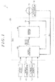
FIG. 1 is a block diagram depicting a general configuration of a control apparatus in an electric power steering system of the present embodiment; -
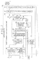
FIG. 2 is a block diagram depicting a general configuration of a microcomputer in the electric power steering system of the present embodiment; and -
FIG. 3 is a flowchart illustrating a procedure for correcting an LKA angle command value in the electric power steering system of the present embodiment. - An embodiment will be described below in which a drive assist control apparatus is applied to an electric power steering system for a vehicle.
- As depicted in
FIG. 1 , an electric power steering system (EPS) 1 has amotor 10 that applies an assist force to a steering mechanism (not shown) and anECU 20 that controls themotor 10 based on detection results from various sensors mounted in a vehicle. The various sensors used includes: atorque sensor 11 that detects a steering torque Th applied to the steering mechanism, avehicle speed sensor 12 that detects a vehicle speed V, alateral acceleration sensor 13 that detects a lateral acceleration LA acting on the vehicle, arotation angle sensor 14 that detects a rotation angle θm of themotor 10, and acurrent sensor 15 that detects a value of actual current I supplied to themotor 10. TheECU 20 determines a target assist force to be applied to the steering mechanism based on the state quantities (Th, V, LA, and θm) of the vehicle detected by the sensors, and supplies themotor 10 with driving electric power used to exert the target assist force. - The ECU 20 includes a
microcomputer 30 that generates a motor control signal and adriving circuit 40 that supplies the driving electric power to themotor 10 based on the motor control signal. - As depicted in
FIG. 2 , themicrocomputer 30 has an assist commandvalue calculation unit 31, a current commandvalue calculation unit 32, and a motor controlsignal generation unit 33. - The assist command
value calculation unit 31 calculates an assist command value Ta* based on the steering torque Th, the vehicle speed V, and the lateral acceleration LA that are acquired through thetorque sensor 11, thevehicle speed sensor 12, and thelateral acceleration sensor 13. - The current command
value calculation unit 32 calculates a current command value I* based on the assist command value Ta*. - The motor control
signal generation unit 33 retrieves the current command value I*, the value of actual current I, and the rotation angle θm of themotor 10. The motor controlsignal generation unit 33 uses the rotation angle θm of themotor 10 to convert a phase for the value of actual current I, and performs feedback control according to a deviation between the current command value I* and the value of actual current I to generate a motor control signal. - Now, a configuration of the assist command
value calculation unit 31 will be described in detail. As depicted inFIG. 2 , the assist commandvalue calculation unit 31 has a basic-assist-component calculation unit 50, a target pinionangle calculation unit 51, a distributionratio calculation unit 52, an LKA angle command value calculation unit 53, anLA determination unit 54, an LKA angle command value correction unit 55, anadder 56, a pinionangle calculation unit 57, an anglefeedback control unit 58, and anadder 59. - The basic-assist-
component calculation unit 50 calculates a basic assist component Ta1* that is a basic component of the assist command value Ta* based on the steering torque Th and the vehicle speed V. The basic-assist-component calculation unit 50 sets the absolute value of the basic assist component Ta1* such that the absolute value increases as the absolute value of the steering torque Th increases and the vehicle speed V decreases. - The target pinion
angle calculation unit 51 uses the basic assist component Ta1* calculated by the basic-assist-component calculation unit 50 and the steering torque Th detected by thetorque sensor 11 to calculate a pinion angle command value θp corresponding to the driver's steering based on an ideal model. The pinion angle command value θp is a target value for a pinion angle θ that is a rotation angle of a pinion shaft (not shown) of a rack-and-pinion mechanism that steers the steered wheels in accordance with the steering. The pinion angle θ is obtained from the rotation angle θm of themotor 10 or the like. The ideal model is a model of an ideal pinion angle command value θp that the vehicle should have in association with the basic assist component Ta1* and the steering torque Th, and the ideal model is obtained through experiment or the like in advance. - The LKA angle command value calculation unit 53 performs lane keeping assist (LKA) control as an example of drive assist control. The LKA angle command value calculation unit 53 calculates an LKA angle command value θLK based on the steering torque Th and the vehicle speed V. In the LKA control, the
motor 10 is controlled such that the vehicle travels along a white line on a road recognized by anexternal detector 53a such as a camera. - Based on the pinion angle command value θp calculated by the target pinion
angle calculation unit 51 and the LKA angle command value θLK calculated by the LKA angle command value calculation unit 53, the distributionratio calculation unit 52 calculates a distribution ratio D using the following expression.
- The distribution ratio D indicates the proportion of the LKA angle command value θLK in the sum of the LKA angle command value θLK and the pinion angle command value θp. On the right side of Expression (1), absolute values are used for a denominator and a numerator. This is to prevent the distribution ratio D from being overestimated. That is, when the LKA angle command value θLK and the pinion angle command value θp have opposite signs, the LKA angle command value θLK and the pinion angle command value θp negate each other in the denominator of Expression (1). Thus, the absolute value of the denominator in Expression (1) is small. As the denominator in Expression (1) is near zero, the distribution ratio D is excessively higher than the proper value. Thus, the distribution ratio D can be more accurately calculated by determining the distribution ratio D after executing processing obtaining absolute values of the LKA angle command value θLK and the pinion angle command value θp.
- The LA determination unit 45 generates an LA determination flag based on the distribution ratio D, the lateral acceleration LA, and a lateral acceleration threshold (LA threshold) T that have been received. That is, the
LA determination unit 54 compares a lateral acceleration LA' related to the LKA angle command value θLK calculated based on Expression (2) with the LA threshold T stored in a memory (not shown) or the like to generate the LA determination flag. The lateral acceleration LA' is a lateral acceleration resulting from LKA control performed on the lateral acceleration LA. The LA threshold T is a value set based on mapping or an empirical rule and is set to such a limit value for the lateral acceleration LA that does not cause discomfort to the driver.
- Since the level of the driver's discomfort is likely to increase as the lateral acceleration LA increases, the lateral acceleration LA is preferably reduced. However, a simple reduction in lateral acceleration LA reduces not only the lateral acceleration LA' resulting from the LKA control but also a lateral acceleration resulting from the driver's steering. That is, since the lateral acceleration is attenuated by attenuating the pinion angle command value θp resulting from the driver's steering, the driver's desired assist force may not be exerted. Thus, instead of simply attenuating the lateral acceleration LA, it is preferable to attenuate the lateral acceleration LA' resulting from the LKA control without attenuating the lateral acceleration resulting from the driver's steering. That is, the LKA angle command value θLK resulting from the LKA control is attenuated without attenuating the pinion angle command value θp resulting from the driver's steering.
- Thus, in the present embodiment, the LKA angle command value θLK is corrected by comparing the lateral acceleration LA' calculated in accordance with Expression (2) with the LA threshold T. That is, when the lateral acceleration LA' is higher than the LA threshold T, the
LA determination unit 54 generates an LA determination flag indicating that the lateral acceleration LA' is to be attenuated. In contrast, when the lateral acceleration LA' is equal to or lower than the LA threshold T, theLA determination unit 54 generates an LA determination flag indicating that the lateral acceleration LA' is not to be attenuated. - The LKA angle command value correction unit 55 corrects the LKA angle command value θLK in accordance with the LA determination flag. Specifically, the LKA angle command value correction unit 55 includes a
low pass filter 55a that progressively reduces the LKA angle command value θLK. When the LA determination flag indicates that the lateral acceleration LA' is to be attenuated, the LKA angle command value correction unit 55 progressively reduces the LKA angle command value θLK by use of thelow pass filter 55a to generate a filtered LKA angle command value θLK'. In contrast, when the LA determination flag indicates that the lateral acceleration LA' is not to be attenuated, the LKA angle command value correction unit 55 does not correct the LKA angle command value θLK. In other words, attenuation of the LKA angle command value θLK by use of thelow pass filter 55a is not performed. - The
adder 56 calculates the sum of the pinion angle command value θp calculated by the target pinionangle calculation unit 51 and the filtered LKA angle command value θLK' or the LKA angle command value θLK calculated by the LKA angle command value correction unit 55 to determine an angle command value θ*. - The pinion
angle calculation unit 57 calculates the pinion angle θ based on the rotation angle θm of themotor 10. - The angle
feedback control unit 58 performs feedback control based on the deviation of the pinion angle θ from the angle command value θ* in order to match the pinion angle θ with the angle command value θ*, and calculates a correcting assist component Ta2*. - The
adder 59 calculates the assist command value Ta* by adding the correcting assist component Ta2* to the basic assist component Ta1*. - Now, a procedure of correction processing for the LKA angle command value θLK executed by the assist command
value calculation unit 31 will be described using a flowchart. - As depicted in
FIG. 3 , first, the lateral acceleration LA' related to the LKA angle command value θLK is calculated (step S1). - Next, the assist command
value calculation unit 31 determines whether or not the lateral acceleration LA' related to the LKA angle command value θLK is higher than the LA threshold T (step S2). - When the lateral acceleration LA' related to the LKA angle command value θLK is higher than the LA threshold T (YES in step S2), low pass filter (LPF) processing of progressively reducing the LKA angle command value θLK by use of the
low pass filter 55a is executed (step S3) to generate the filtered LKA angle command value θLK' (step S4). The correction processing is then ended. - When the lateral acceleration LA' related to the LKA angle command value θLK is equal to or lower than the LA threshold T (NO in step S2), the LKA angle command value θLK is not corrected but is directly adopted (step S5). The correction processing is then ended.
- The above flow of the procedure allows attenuation of a component of the lateral acceleration LA that is related to the LKA angle command value θLK resulting from the LKA control without attenuating a component of the lateral acceleration LA that is related to the pinion angle command value θp resulting from the driver's steering. Thus, the lateral acceleration LA' can be more accurately attenuated.
- Effects of the present embodiment will be described.
- (1) Attenuating the LKA angle command value θLK allows the lateral acceleration LA' resulting from the LKA control to be more properly attenuated. That is, when the lateral acceleration LA' related to the LKA angle command value θLK is higher than the LA threshold T, the LKA angle command value θLK is filtered by the
low pass filter 55a and is thus attenuated. Therefore, the LKA angle command value θLK resulting from the LKA control can be attenuated without attenuating the pinion angle command value θp resulting from the driver's steering. In other words, attenuating the lateral acceleration LA' allows the lateral acceleration LA to be attenuated with the driver's desired assist force ensured. - (2) Whether or not to correct the lateral acceleration LA by attenuating the LKA angle command value θLK can be determined simply by using the distribution ratio D between the pinion angle command value θp resulting from the driver's steering and the LKA angle command value θLK resulting from the LKA control to determine whether or not the lateral acceleration LA' is higher than the LA threshold T. That is, whether or not to attenuate the LKA angle command value θLK can be determined by simple determination of whether or not the lateral acceleration LA' is higher than the LA threshold T.
- (3) A more accurate distribution ratio D can be determined by executing the processing of obtaining absolute values of the LKA angle command value θLK and the pinion angle command value θp into the respective absolute values before determining the distribution ratio D. In the case where the absolute-value processing is not executed, when the LKA angle command value θLK and the pinion angle command value θp have opposite signs, the distribution ratio D may be overestimated because the denominator of the distribution ratio D is underestimated. In the present embodiment, a more accurate distribution ratio D can be determined by executing the absolute-value processing on the LKA angle command value θLK and the pinion angle command value θp before determining the distribution ratio D.
- The present embodiment may be modified as follows.
- In the present embodiment, the LKA angle command value correction unit 55 uses the determination flag to determine whether or not the LKA angle command value θLK should be filtered by the
low pass filter 55a. However, the invention is not limited to this. For example, the following configuration is possible: when the LA determination flag indicating that the lateral acceleration LA' is not to be attenuated is input, power supply to the LKA angle command value correction unit 55 may be stopped, and the LKA angle command value calculation unit 53 may output the LKA angle command value θLK to theadder 56. Theadder 56 then adds the pinion angle command value θp and the LKA angle command value θLK together to obtain the angle command value θ*. The anglefeedback control unit 58 then uses the angle command value θ* to perform feedback control in order to match the pinion angle θ with the angle command value θ*. - In the present embodiment, a method for determining the distribution ratio D is not limited to Expression (1). For example, the LKA angle command value θLK and the pinion angle command value θp may be weighted based on, for example, an empirical rule.
- In the present embodiment, the processing of obtaining absolute values of the LKA angle command value θLK and the pinion angle command value θp is executed before the distribution ratio D is determined. However, the absolute-value processing need not be executed. In this case, the distribution ratio D is overestimated when the LKA angle command value θLK and the pinion angle command value θp have opposite signs, but an accurate distribution ratio D can be determined when the LKA angle command value θLK and the pinion angle command value θp have the same sign.
- In the present embodiment, although the LA threshold T is constant, the LA threshold T may vary according to the vehicle speed V. That is, the lateral acceleration LA that cause discomfort to the driver varies according to the vehicle speed V. Alternatively, calculation processing may be executed in which the LKA angle command value θLK is progressively reduced according to the lateral acceleration LA without the use of the LA threshold T.
- In the present embodiment, although the LKA angle command value correction unit 55 is provided with one
low pass filter 55a, a plurality of filters may be provided in the LKA angle command value correction unit 55. For example, any of these filters may be selected according to the lateral acceleration LA. - In the present embodiment, the pinion angle θ is used. However, the invention is not limited to this. For example, a steering angle may be used.
- In the present embodiment, the lane keeping assist control is used as an example of drive assist control. However, the invention is not limited to this. For example, advanced driver assistance system (ADAS) such as parking assist or lane change assist may be used.
- In the present embodiment, the LKA angle command value calculation unit 53 is provided in the
ECU 20 that controls the EPS1. However, the LKA angle command value calculation unit 53 may be provided in an ECU for the vehicle body. - In the present embodiment, the electric power steering system and the drive assist control apparatus are combined together. However, the invention is not limited to this. For example, a steer-by-wire system and the drive assist control apparatus may be combined together.
- The drive assist control apparatus of the present embodiment may be embodied in any electric power steering systems. For example, the drive assist control apparatus of the present embodiment may be embodied in a columnar electric power steering system or a rack-parallel electric power steering system.
Claims (5)
- A drive assist control apparatus that controls steering of a vehicle in accordance with a sum of a first angle command value and a second angle command value, which is a target value for a rotation angle of a rotating shaft of a steering mechanism, the drive assist control apparatus comprising:a first calculation unit that calculates the first angle command value for a drive assist;a second calculation unit that calculates the second angle command value based on a steering torque;a distribution ratio calculation unit that calculates a distribution ratio that is a proportion of the first angle command value in the sum of the first angle command value and the second angle command value;a determination unit that multiplies a lateral acceleration of the vehicle by the distribution ratio to determine the lateral acceleration related to the first angle command value and determines whether or not the lateral acceleration related to the first angle command value needs to be reduced; anda correction unit that progressively reduces the first angle command value in accordance with a determination result from the determination unit; whereinthe correction unit corrects the first angle command value when the determination result indicates that the lateral acceleration related to the first angle command value needs to be reduced, and does not corrects the first angle command value when the determination result indicates that the lateral acceleration related to the first angle command value need not be reduced.
- The drive assist control apparatus according to claim 1, wherein
the determination unit determines that the first angle command value needs to be reduced when the lateral acceleration related to the first angle command value is higher than a predetermined threshold, and
determines that the first angle command value need not be reduced when the lateral acceleration related to the first angle command value is equal to or lower than the predetermined threshold. - The drive assist control apparatus according to claim 1 or 2, wherein
the correction unit has a low pass filter that progressively reduces the first angle command value. - The drive assist control apparatus according to any one of claims 1 to 3, wherein
the distribution ratio calculation unit calculates the distribution ratio using absolute values of the first angle command value and the second angle command value. - The drive assist control apparatus according to any one of claims 1 to 4, wherein
the drive assist is a lane keeping assist in which traveling of the vehicle is assisted based on information of a white line on a road recognized by an external detector, and
the first calculation unit calculates the first angle command value based on the information of the white line and a steering direction.
Applications Claiming Priority (1)
| Application Number | Priority Date | Filing Date | Title |
|---|---|---|---|
| JP2015025487A JP6439479B2 (en) | 2015-02-12 | 2015-02-12 | Driving support control device |
Publications (2)
| Publication Number | Publication Date |
|---|---|
| EP3056410A1 true EP3056410A1 (en) | 2016-08-17 |
| EP3056410B1 EP3056410B1 (en) | 2018-08-01 |
Family
ID=55527738
Family Applications (1)
| Application Number | Title | Priority Date | Filing Date |
|---|---|---|---|
| EP16155163.5A Active EP3056410B1 (en) | 2015-02-12 | 2016-02-11 | Drive assist control apparatus |
Country Status (4)
| Country | Link |
|---|---|
| US (1) | US9731756B2 (en) |
| EP (1) | EP3056410B1 (en) |
| JP (1) | JP6439479B2 (en) |
| CN (1) | CN105882738B (en) |
Families Citing this family (9)
| Publication number | Priority date | Publication date | Assignee | Title |
|---|---|---|---|---|
| JP6519332B2 (en) * | 2015-06-11 | 2019-05-29 | 株式会社ジェイテクト | Driving support control device |
| JP6911300B2 (en) * | 2016-08-30 | 2021-07-28 | 株式会社ジェイテクト | Driving support device |
| JP6536548B2 (en) * | 2016-12-01 | 2019-07-03 | トヨタ自動車株式会社 | In-lane travel support device |
| DE102017207391B4 (en) * | 2017-05-03 | 2019-02-28 | Ford Global Technologies, Llc | A method for generating a resulting auxiliary steering torque adapted to a current driving situation of a vehicle using an active steering assistance system and steering assistance system |
| CN111278714B (en) | 2017-11-02 | 2022-07-05 | 株式会社捷太格特 | Steering control device |
| KR102636740B1 (en) * | 2018-12-17 | 2024-02-15 | 현대자동차주식회사 | Vehicle and control method of the vehicle |
| US12012165B2 (en) * | 2020-12-23 | 2024-06-18 | Nsk Ltd. | Control device for electric power steering device and control method for the same |
| DE102021201141A1 (en) * | 2021-02-08 | 2022-08-11 | Continental Automotive Gmbh | Control device and method for steering angle control of a vehicle |
| WO2022244233A1 (en) * | 2021-05-21 | 2022-11-24 | 三菱電機株式会社 | Vehicle steering system |
Citations (5)
| Publication number | Priority date | Publication date | Assignee | Title |
|---|---|---|---|---|
| EP1170651A2 (en) * | 2000-07-06 | 2002-01-09 | Nissan Motor Company, Limited | Lane following vehicle control |
| EP1577194A1 (en) * | 2004-03-16 | 2005-09-21 | Toyoda Koki Kabushiki Kaisha | Steering apparatus for vehicle and method for controlling the same |
| EP2054288A2 (en) * | 2006-08-22 | 2009-05-06 | Toyota Jidosha Kabusiki Kaisha | Steering assist system and steering assist method |
| US20090157263A1 (en) * | 2007-12-13 | 2009-06-18 | Hyundai Motor Company | System and method for keeping a vehicle in a lane |
| EP2585356A1 (en) * | 2010-06-25 | 2013-05-01 | Toyota Jidosha Kabushiki Kaisha | Control device and control method for vehicle |
Family Cites Families (16)
| Publication number | Priority date | Publication date | Assignee | Title |
|---|---|---|---|---|
| JPH07179140A (en) * | 1993-12-24 | 1995-07-18 | Nissan Motor Co Ltd | Autopilot for vehicle |
| JP3877395B2 (en) * | 1997-10-23 | 2007-02-07 | 本田技研工業株式会社 | Steering device |
| JP4231910B2 (en) * | 2000-04-25 | 2009-03-04 | 日産自動車株式会社 | Lane keeping device |
| JP4639771B2 (en) * | 2004-11-24 | 2011-02-23 | トヨタ自動車株式会社 | Vehicle steering control device |
| JP4579056B2 (en) * | 2005-06-02 | 2010-11-10 | 本田技研工業株式会社 | Vehicle steering system |
| KR101285052B1 (en) * | 2008-12-26 | 2013-07-10 | 도요타 지도샤(주) | Driving support system of vehicle |
| JP5421019B2 (en) * | 2009-08-03 | 2014-02-19 | トヨタ自動車株式会社 | Vehicle travel support device |
| JP5036780B2 (en) * | 2009-10-06 | 2012-09-26 | トヨタ自動車株式会社 | Vehicle control device |
| WO2012001786A1 (en) * | 2010-06-30 | 2012-01-05 | トヨタ自動車株式会社 | Control unit for vehicle |
| JP5429142B2 (en) * | 2010-11-18 | 2014-02-26 | 日本精工株式会社 | Electric power steering device |
| JP5766941B2 (en) * | 2010-12-01 | 2015-08-19 | トヨタ自動車株式会社 | Driving support device |
| US8935071B2 (en) * | 2011-05-05 | 2015-01-13 | GM Global Technology Operations LLC | Optimal fusion of electric park brake and hydraulic brake sub-system functions to control vehicle direction |
| JP2013075614A (en) * | 2011-09-30 | 2013-04-25 | Ntn Corp | Control device for steer-by-wire type steering mechanism |
| JP5994480B2 (en) * | 2012-08-22 | 2016-09-21 | 株式会社ジェイテクト | Electric power steering device |
| JP5994481B2 (en) * | 2012-08-22 | 2016-09-21 | 株式会社ジェイテクト | Electric power steering device |
| US9393960B2 (en) * | 2012-11-28 | 2016-07-19 | Toyota Jidosha Kabushiki Kaisha | Vehicle cruise control device |
-
2015
- 2015-02-12 JP JP2015025487A patent/JP6439479B2/en active Active
-
2016
- 2016-02-04 US US15/015,997 patent/US9731756B2/en active Active
- 2016-02-05 CN CN201610082587.4A patent/CN105882738B/en active Active
- 2016-02-11 EP EP16155163.5A patent/EP3056410B1/en active Active
Patent Citations (5)
| Publication number | Priority date | Publication date | Assignee | Title |
|---|---|---|---|---|
| EP1170651A2 (en) * | 2000-07-06 | 2002-01-09 | Nissan Motor Company, Limited | Lane following vehicle control |
| EP1577194A1 (en) * | 2004-03-16 | 2005-09-21 | Toyoda Koki Kabushiki Kaisha | Steering apparatus for vehicle and method for controlling the same |
| EP2054288A2 (en) * | 2006-08-22 | 2009-05-06 | Toyota Jidosha Kabusiki Kaisha | Steering assist system and steering assist method |
| US20090157263A1 (en) * | 2007-12-13 | 2009-06-18 | Hyundai Motor Company | System and method for keeping a vehicle in a lane |
| EP2585356A1 (en) * | 2010-06-25 | 2013-05-01 | Toyota Jidosha Kabushiki Kaisha | Control device and control method for vehicle |
Also Published As
| Publication number | Publication date |
|---|---|
| EP3056410B1 (en) | 2018-08-01 |
| CN105882738B (en) | 2019-09-27 |
| JP2016147590A (en) | 2016-08-18 |
| CN105882738A (en) | 2016-08-24 |
| JP6439479B2 (en) | 2018-12-19 |
| US9731756B2 (en) | 2017-08-15 |
| US20160244092A1 (en) | 2016-08-25 |
Similar Documents
| Publication | Publication Date | Title |
|---|---|---|
| EP3056410B1 (en) | Drive assist control apparatus | |
| EP3213979B1 (en) | Steering control system | |
| EP2842833B1 (en) | Vehicle power steering system | |
| CN107826163B (en) | Steering control device | |
| US9002579B2 (en) | Steering assist device | |
| CN111315637B (en) | Electric power steering | |
| EP2998198B1 (en) | Electric power steering system | |
| EP2700565B1 (en) | Electric power steering system | |
| JP6380014B2 (en) | Electric power steering device | |
| US9610973B2 (en) | Motor-driven power steering apparatus | |
| JP6776998B2 (en) | Autonomous driving system | |
| JP6413723B2 (en) | Electric power steering device | |
| JP6303793B2 (en) | Electric power steering device | |
| US20120123642A1 (en) | Vehicle running control apparatus | |
| CN104176114B (en) | Steering control device and steering speed detection method | |
| EP3216675B1 (en) | Steering control system | |
| US20170334480A1 (en) | Electric power steering device | |
| US9481392B2 (en) | Electric power steering device | |
| JP6220688B2 (en) | Electric power steering device | |
| EP2639137A2 (en) | Vehicle steering control system | |
| JP6834936B2 (en) | Steering assist device | |
| JP6519332B2 (en) | Driving support control device | |
| KR101958476B1 (en) | Apparatus and Method Improving Performance of LKAS | |
| KR20180117383A (en) | Steering Torque correction Apparatus of Vehicle and Method Thereof |
Legal Events
| Date | Code | Title | Description |
|---|---|---|---|
| PUAI | Public reference made under article 153(3) epc to a published international application that has entered the european phase |
Free format text: ORIGINAL CODE: 0009012 |
|
| AK | Designated contracting states |
Kind code of ref document: A1 Designated state(s): AL AT BE BG CH CY CZ DE DK EE ES FI FR GB GR HR HU IE IS IT LI LT LU LV MC MK MT NL NO PL PT RO RS SE SI SK SM TR |
|
| AX | Request for extension of the european patent |
Extension state: BA ME |
|
| STAA | Information on the status of an ep patent application or granted ep patent |
Free format text: STATUS: REQUEST FOR EXAMINATION WAS MADE |
|
| 17P | Request for examination filed |
Effective date: 20170217 |
|
| RBV | Designated contracting states (corrected) |
Designated state(s): AL AT BE BG CH CY CZ DE DK EE ES FI FR GB GR HR HU IE IS IT LI LT LU LV MC MK MT NL NO PL PT RO RS SE SI SK SM TR |
|
| GRAP | Despatch of communication of intention to grant a patent |
Free format text: ORIGINAL CODE: EPIDOSNIGR1 |
|
| STAA | Information on the status of an ep patent application or granted ep patent |
Free format text: STATUS: GRANT OF PATENT IS INTENDED |
|
| RIC1 | Information provided on ipc code assigned before grant |
Ipc: B62D 6/00 20060101AFI20180118BHEP Ipc: B62D 15/02 20060101ALI20180118BHEP |
|
| INTG | Intention to grant announced |
Effective date: 20180207 |
|
| GRAS | Grant fee paid |
Free format text: ORIGINAL CODE: EPIDOSNIGR3 |
|
| GRAA | (expected) grant |
Free format text: ORIGINAL CODE: 0009210 |
|
| STAA | Information on the status of an ep patent application or granted ep patent |
Free format text: STATUS: THE PATENT HAS BEEN GRANTED |
|
| RIN1 | Information on inventor provided before grant (corrected) |
Inventor name: MATSUO, SHIGETO |
|
| AK | Designated contracting states |
Kind code of ref document: B1 Designated state(s): AL AT BE BG CH CY CZ DE DK EE ES FI FR GB GR HR HU IE IS IT LI LT LU LV MC MK MT NL NO PL PT RO RS SE SI SK SM TR |
|
| REG | Reference to a national code |
Ref country code: GB Ref legal event code: FG4D |
|
| REG | Reference to a national code |
Ref country code: CH Ref legal event code: EP Ref country code: AT Ref legal event code: REF Ref document number: 1023932 Country of ref document: AT Kind code of ref document: T Effective date: 20180815 |
|
| REG | Reference to a national code |
Ref country code: IE Ref legal event code: FG4D |
|
| REG | Reference to a national code |
Ref country code: DE Ref legal event code: R096 Ref document number: 602016004348 Country of ref document: DE |
|
| REG | Reference to a national code |
Ref country code: NL Ref legal event code: MP Effective date: 20180801 |
|
| REG | Reference to a national code |
Ref country code: LT Ref legal event code: MG4D |
|
| REG | Reference to a national code |
Ref country code: AT Ref legal event code: MK05 Ref document number: 1023932 Country of ref document: AT Kind code of ref document: T Effective date: 20180801 |
|
| PG25 | Lapsed in a contracting state [announced via postgrant information from national office to epo] |
Ref country code: GR Free format text: LAPSE BECAUSE OF FAILURE TO SUBMIT A TRANSLATION OF THE DESCRIPTION OR TO PAY THE FEE WITHIN THE PRESCRIBED TIME-LIMIT Effective date: 20181102 Ref country code: SE Free format text: LAPSE BECAUSE OF FAILURE TO SUBMIT A TRANSLATION OF THE DESCRIPTION OR TO PAY THE FEE WITHIN THE PRESCRIBED TIME-LIMIT Effective date: 20180801 Ref country code: BG Free format text: LAPSE BECAUSE OF FAILURE TO SUBMIT A TRANSLATION OF THE DESCRIPTION OR TO PAY THE FEE WITHIN THE PRESCRIBED TIME-LIMIT Effective date: 20181101 Ref country code: NO Free format text: LAPSE BECAUSE OF FAILURE TO SUBMIT A TRANSLATION OF THE DESCRIPTION OR TO PAY THE FEE WITHIN THE PRESCRIBED TIME-LIMIT Effective date: 20181101 Ref country code: NL Free format text: LAPSE BECAUSE OF FAILURE TO SUBMIT A TRANSLATION OF THE DESCRIPTION OR TO PAY THE FEE WITHIN THE PRESCRIBED TIME-LIMIT Effective date: 20180801 Ref country code: PL Free format text: LAPSE BECAUSE OF FAILURE TO SUBMIT A TRANSLATION OF THE DESCRIPTION OR TO PAY THE FEE WITHIN THE PRESCRIBED TIME-LIMIT Effective date: 20180801 Ref country code: FI Free format text: LAPSE BECAUSE OF FAILURE TO SUBMIT A TRANSLATION OF THE DESCRIPTION OR TO PAY THE FEE WITHIN THE PRESCRIBED TIME-LIMIT Effective date: 20180801 Ref country code: LT Free format text: LAPSE BECAUSE OF FAILURE TO SUBMIT A TRANSLATION OF THE DESCRIPTION OR TO PAY THE FEE WITHIN THE PRESCRIBED TIME-LIMIT Effective date: 20180801 Ref country code: RS Free format text: LAPSE BECAUSE OF FAILURE TO SUBMIT A TRANSLATION OF THE DESCRIPTION OR TO PAY THE FEE WITHIN THE PRESCRIBED TIME-LIMIT Effective date: 20180801 Ref country code: IS Free format text: LAPSE BECAUSE OF FAILURE TO SUBMIT A TRANSLATION OF THE DESCRIPTION OR TO PAY THE FEE WITHIN THE PRESCRIBED TIME-LIMIT Effective date: 20181201 Ref country code: AT Free format text: LAPSE BECAUSE OF FAILURE TO SUBMIT A TRANSLATION OF THE DESCRIPTION OR TO PAY THE FEE WITHIN THE PRESCRIBED TIME-LIMIT Effective date: 20180801 |
|
| PG25 | Lapsed in a contracting state [announced via postgrant information from national office to epo] |
Ref country code: AL Free format text: LAPSE BECAUSE OF FAILURE TO SUBMIT A TRANSLATION OF THE DESCRIPTION OR TO PAY THE FEE WITHIN THE PRESCRIBED TIME-LIMIT Effective date: 20180801 Ref country code: LV Free format text: LAPSE BECAUSE OF FAILURE TO SUBMIT A TRANSLATION OF THE DESCRIPTION OR TO PAY THE FEE WITHIN THE PRESCRIBED TIME-LIMIT Effective date: 20180801 Ref country code: HR Free format text: LAPSE BECAUSE OF FAILURE TO SUBMIT A TRANSLATION OF THE DESCRIPTION OR TO PAY THE FEE WITHIN THE PRESCRIBED TIME-LIMIT Effective date: 20180801 |
|
| PG25 | Lapsed in a contracting state [announced via postgrant information from national office to epo] |
Ref country code: EE Free format text: LAPSE BECAUSE OF FAILURE TO SUBMIT A TRANSLATION OF THE DESCRIPTION OR TO PAY THE FEE WITHIN THE PRESCRIBED TIME-LIMIT Effective date: 20180801 Ref country code: IT Free format text: LAPSE BECAUSE OF FAILURE TO SUBMIT A TRANSLATION OF THE DESCRIPTION OR TO PAY THE FEE WITHIN THE PRESCRIBED TIME-LIMIT Effective date: 20180801 Ref country code: RO Free format text: LAPSE BECAUSE OF FAILURE TO SUBMIT A TRANSLATION OF THE DESCRIPTION OR TO PAY THE FEE WITHIN THE PRESCRIBED TIME-LIMIT Effective date: 20180801 Ref country code: CZ Free format text: LAPSE BECAUSE OF FAILURE TO SUBMIT A TRANSLATION OF THE DESCRIPTION OR TO PAY THE FEE WITHIN THE PRESCRIBED TIME-LIMIT Effective date: 20180801 Ref country code: ES Free format text: LAPSE BECAUSE OF FAILURE TO SUBMIT A TRANSLATION OF THE DESCRIPTION OR TO PAY THE FEE WITHIN THE PRESCRIBED TIME-LIMIT Effective date: 20180801 |
|
| REG | Reference to a national code |
Ref country code: DE Ref legal event code: R097 Ref document number: 602016004348 Country of ref document: DE |
|
| PG25 | Lapsed in a contracting state [announced via postgrant information from national office to epo] |
Ref country code: SK Free format text: LAPSE BECAUSE OF FAILURE TO SUBMIT A TRANSLATION OF THE DESCRIPTION OR TO PAY THE FEE WITHIN THE PRESCRIBED TIME-LIMIT Effective date: 20180801 Ref country code: DK Free format text: LAPSE BECAUSE OF FAILURE TO SUBMIT A TRANSLATION OF THE DESCRIPTION OR TO PAY THE FEE WITHIN THE PRESCRIBED TIME-LIMIT Effective date: 20180801 Ref country code: SM Free format text: LAPSE BECAUSE OF FAILURE TO SUBMIT A TRANSLATION OF THE DESCRIPTION OR TO PAY THE FEE WITHIN THE PRESCRIBED TIME-LIMIT Effective date: 20180801 |
|
| PLBE | No opposition filed within time limit |
Free format text: ORIGINAL CODE: 0009261 |
|
| STAA | Information on the status of an ep patent application or granted ep patent |
Free format text: STATUS: NO OPPOSITION FILED WITHIN TIME LIMIT |
|
| 26N | No opposition filed |
Effective date: 20190503 |
|
| PG25 | Lapsed in a contracting state [announced via postgrant information from national office to epo] |
Ref country code: SI Free format text: LAPSE BECAUSE OF FAILURE TO SUBMIT A TRANSLATION OF THE DESCRIPTION OR TO PAY THE FEE WITHIN THE PRESCRIBED TIME-LIMIT Effective date: 20180801 |
|
| REG | Reference to a national code |
Ref country code: CH Ref legal event code: PL |
|
| PG25 | Lapsed in a contracting state [announced via postgrant information from national office to epo] |
Ref country code: MC Free format text: LAPSE BECAUSE OF FAILURE TO SUBMIT A TRANSLATION OF THE DESCRIPTION OR TO PAY THE FEE WITHIN THE PRESCRIBED TIME-LIMIT Effective date: 20180801 Ref country code: LU Free format text: LAPSE BECAUSE OF NON-PAYMENT OF DUE FEES Effective date: 20190211 |
|
| REG | Reference to a national code |
Ref country code: BE Ref legal event code: MM Effective date: 20190228 |
|
| REG | Reference to a national code |
Ref country code: IE Ref legal event code: MM4A |
|
| PG25 | Lapsed in a contracting state [announced via postgrant information from national office to epo] |
Ref country code: CH Free format text: LAPSE BECAUSE OF NON-PAYMENT OF DUE FEES Effective date: 20190228 Ref country code: LI Free format text: LAPSE BECAUSE OF NON-PAYMENT OF DUE FEES Effective date: 20190228 |
|
| PG25 | Lapsed in a contracting state [announced via postgrant information from national office to epo] |
Ref country code: IE Free format text: LAPSE BECAUSE OF NON-PAYMENT OF DUE FEES Effective date: 20190211 |
|
| PG25 | Lapsed in a contracting state [announced via postgrant information from national office to epo] |
Ref country code: BE Free format text: LAPSE BECAUSE OF NON-PAYMENT OF DUE FEES Effective date: 20190228 |
|
| PG25 | Lapsed in a contracting state [announced via postgrant information from national office to epo] |
Ref country code: TR Free format text: LAPSE BECAUSE OF FAILURE TO SUBMIT A TRANSLATION OF THE DESCRIPTION OR TO PAY THE FEE WITHIN THE PRESCRIBED TIME-LIMIT Effective date: 20180801 |
|
| PG25 | Lapsed in a contracting state [announced via postgrant information from national office to epo] |
Ref country code: PT Free format text: LAPSE BECAUSE OF FAILURE TO SUBMIT A TRANSLATION OF THE DESCRIPTION OR TO PAY THE FEE WITHIN THE PRESCRIBED TIME-LIMIT Effective date: 20181201 Ref country code: MT Free format text: LAPSE BECAUSE OF NON-PAYMENT OF DUE FEES Effective date: 20190211 |
|
| GBPC | Gb: european patent ceased through non-payment of renewal fee |
Effective date: 20200211 |
|
| PG25 | Lapsed in a contracting state [announced via postgrant information from national office to epo] |
Ref country code: GB Free format text: LAPSE BECAUSE OF NON-PAYMENT OF DUE FEES Effective date: 20200211 |
|
| PG25 | Lapsed in a contracting state [announced via postgrant information from national office to epo] |
Ref country code: CY Free format text: LAPSE BECAUSE OF FAILURE TO SUBMIT A TRANSLATION OF THE DESCRIPTION OR TO PAY THE FEE WITHIN THE PRESCRIBED TIME-LIMIT Effective date: 20180801 |
|
| PG25 | Lapsed in a contracting state [announced via postgrant information from national office to epo] |
Ref country code: HU Free format text: LAPSE BECAUSE OF FAILURE TO SUBMIT A TRANSLATION OF THE DESCRIPTION OR TO PAY THE FEE WITHIN THE PRESCRIBED TIME-LIMIT; INVALID AB INITIO Effective date: 20160211 |
|
| PG25 | Lapsed in a contracting state [announced via postgrant information from national office to epo] |
Ref country code: MK Free format text: LAPSE BECAUSE OF FAILURE TO SUBMIT A TRANSLATION OF THE DESCRIPTION OR TO PAY THE FEE WITHIN THE PRESCRIBED TIME-LIMIT Effective date: 20180801 |
|
| PGFP | Annual fee paid to national office [announced via postgrant information from national office to epo] |
Ref country code: FR Payment date: 20241231 Year of fee payment: 10 |
|
| PGFP | Annual fee paid to national office [announced via postgrant information from national office to epo] |
Ref country code: DE Payment date: 20241231 Year of fee payment: 10 |