EP3056368A1 - Engine suspension system - Google Patents
Engine suspension system Download PDFInfo
- Publication number
- EP3056368A1 EP3056368A1 EP16155133.8A EP16155133A EP3056368A1 EP 3056368 A1 EP3056368 A1 EP 3056368A1 EP 16155133 A EP16155133 A EP 16155133A EP 3056368 A1 EP3056368 A1 EP 3056368A1
- Authority
- EP
- European Patent Office
- Prior art keywords
- engine
- spring characteristics
- vehicle
- engine mount
- liquid chamber
- Prior art date
- Legal status (The legal status is an assumption and is not a legal conclusion. Google has not performed a legal analysis and makes no representation as to the accuracy of the status listed.)
- Granted
Links
- 239000000725 suspension Substances 0.000 title claims abstract description 20
- 239000007788 liquid Substances 0.000 claims description 43
- 238000013016 damping Methods 0.000 claims description 41
- 230000008859 change Effects 0.000 description 21
- 230000005540 biological transmission Effects 0.000 description 11
- 238000000034 method Methods 0.000 description 4
- 230000003247 decreasing effect Effects 0.000 description 3
- 230000000694 effects Effects 0.000 description 3
- 230000009467 reduction Effects 0.000 description 3
- 241000711975 Vesicular stomatitis virus Species 0.000 description 2
- 230000008569 process Effects 0.000 description 2
- 230000009471 action Effects 0.000 description 1
- 238000006073 displacement reaction Methods 0.000 description 1
- 238000005516 engineering process Methods 0.000 description 1
- 239000000446 fuel Substances 0.000 description 1
- 230000006872 improvement Effects 0.000 description 1
- 238000002347 injection Methods 0.000 description 1
- 239000007924 injection Substances 0.000 description 1
- 238000005259 measurement Methods 0.000 description 1
- 230000001629 suppression Effects 0.000 description 1
Images


Classifications
-
- B—PERFORMING OPERATIONS; TRANSPORTING
- B60—VEHICLES IN GENERAL
- B60K—ARRANGEMENT OR MOUNTING OF PROPULSION UNITS OR OF TRANSMISSIONS IN VEHICLES; ARRANGEMENT OR MOUNTING OF PLURAL DIVERSE PRIME-MOVERS IN VEHICLES; AUXILIARY DRIVES FOR VEHICLES; INSTRUMENTATION OR DASHBOARDS FOR VEHICLES; ARRANGEMENTS IN CONNECTION WITH COOLING, AIR INTAKE, GAS EXHAUST OR FUEL SUPPLY OF PROPULSION UNITS IN VEHICLES
- B60K5/00—Arrangement or mounting of internal-combustion or jet-propulsion units
- B60K5/12—Arrangement of engine supports
- B60K5/1275—Plastically deformable supports
-
- B—PERFORMING OPERATIONS; TRANSPORTING
- B60—VEHICLES IN GENERAL
- B60K—ARRANGEMENT OR MOUNTING OF PROPULSION UNITS OR OF TRANSMISSIONS IN VEHICLES; ARRANGEMENT OR MOUNTING OF PLURAL DIVERSE PRIME-MOVERS IN VEHICLES; AUXILIARY DRIVES FOR VEHICLES; INSTRUMENTATION OR DASHBOARDS FOR VEHICLES; ARRANGEMENTS IN CONNECTION WITH COOLING, AIR INTAKE, GAS EXHAUST OR FUEL SUPPLY OF PROPULSION UNITS IN VEHICLES
- B60K5/00—Arrangement or mounting of internal-combustion or jet-propulsion units
- B60K5/12—Arrangement of engine supports
- B60K5/1283—Adjustable supports, e.g. the mounting or the characteristics being adjustable
-
- B—PERFORMING OPERATIONS; TRANSPORTING
- B60—VEHICLES IN GENERAL
- B60K—ARRANGEMENT OR MOUNTING OF PROPULSION UNITS OR OF TRANSMISSIONS IN VEHICLES; ARRANGEMENT OR MOUNTING OF PLURAL DIVERSE PRIME-MOVERS IN VEHICLES; AUXILIARY DRIVES FOR VEHICLES; INSTRUMENTATION OR DASHBOARDS FOR VEHICLES; ARRANGEMENTS IN CONNECTION WITH COOLING, AIR INTAKE, GAS EXHAUST OR FUEL SUPPLY OF PROPULSION UNITS IN VEHICLES
- B60K5/00—Arrangement or mounting of internal-combustion or jet-propulsion units
- B60K5/12—Arrangement of engine supports
- B60K5/1208—Resilient supports
-
- F—MECHANICAL ENGINEERING; LIGHTING; HEATING; WEAPONS; BLASTING
- F16—ENGINEERING ELEMENTS AND UNITS; GENERAL MEASURES FOR PRODUCING AND MAINTAINING EFFECTIVE FUNCTIONING OF MACHINES OR INSTALLATIONS; THERMAL INSULATION IN GENERAL
- F16F—SPRINGS; SHOCK-ABSORBERS; MEANS FOR DAMPING VIBRATION
- F16F15/00—Suppression of vibrations in systems; Means or arrangements for avoiding or reducing out-of-balance forces, e.g. due to motion
- F16F15/002—Suppression of vibrations in systems; Means or arrangements for avoiding or reducing out-of-balance forces, e.g. due to motion characterised by the control method or circuitry
-
- F—MECHANICAL ENGINEERING; LIGHTING; HEATING; WEAPONS; BLASTING
- F16—ENGINEERING ELEMENTS AND UNITS; GENERAL MEASURES FOR PRODUCING AND MAINTAINING EFFECTIVE FUNCTIONING OF MACHINES OR INSTALLATIONS; THERMAL INSULATION IN GENERAL
- F16F—SPRINGS; SHOCK-ABSORBERS; MEANS FOR DAMPING VIBRATION
- F16F15/00—Suppression of vibrations in systems; Means or arrangements for avoiding or reducing out-of-balance forces, e.g. due to motion
- F16F15/02—Suppression of vibrations of non-rotating, e.g. reciprocating systems; Suppression of vibrations of rotating systems by use of members not moving with the rotating systems
- F16F15/023—Suppression of vibrations of non-rotating, e.g. reciprocating systems; Suppression of vibrations of rotating systems by use of members not moving with the rotating systems using fluid means
- F16F15/027—Suppression of vibrations of non-rotating, e.g. reciprocating systems; Suppression of vibrations of rotating systems by use of members not moving with the rotating systems using fluid means comprising control arrangements
- F16F15/0275—Control of stiffness
-
- F—MECHANICAL ENGINEERING; LIGHTING; HEATING; WEAPONS; BLASTING
- F16—ENGINEERING ELEMENTS AND UNITS; GENERAL MEASURES FOR PRODUCING AND MAINTAINING EFFECTIVE FUNCTIONING OF MACHINES OR INSTALLATIONS; THERMAL INSULATION IN GENERAL
- F16F—SPRINGS; SHOCK-ABSORBERS; MEANS FOR DAMPING VIBRATION
- F16F15/00—Suppression of vibrations in systems; Means or arrangements for avoiding or reducing out-of-balance forces, e.g. due to motion
- F16F15/02—Suppression of vibrations of non-rotating, e.g. reciprocating systems; Suppression of vibrations of rotating systems by use of members not moving with the rotating systems
- F16F15/04—Suppression of vibrations of non-rotating, e.g. reciprocating systems; Suppression of vibrations of rotating systems by use of members not moving with the rotating systems using elastic means
Definitions
- the invention relates to a suspension system for an engine of a vehicle.
- a suspension system for an engine in a vehicle includes an engine mount that supports the engine on the vehicle.
- the engine mount has the function of curbing transmission of engine vibration to the vehicle side, and damping vibration transmitted from a road surface to the vehicle.
- a small spring constant of the engine mount improves the capability of curbing transmission of engine vibration to the vehicle side.
- a high damping coefficient of the engine mount improves the capability of damping vibration transmitted from the road surface to the vehicle.
- JP 2011-80492 A discloses the relationship between the spring constant and the damping coefficient of an engine mount when the engine mount is tuned to predetermined spring characteristics. More specifically, this document discloses the relationship between changes in the spring constant and changes in the damping coefficient with increase of the frequency of engine vibration, under a condition where the engine mount is tuned to the predetermined spring characteristics. In the engine mount tuned to the predetermined spring characteristics, the frequency at which the spring constant is maximized and the frequency at which the damping coefficient is maximized are close to each other.
- the frequency at which the spring constant is maximized and the frequency at which the damping coefficient is maximized are kept close to each other, but the trend in change of the spring constant and the trend in change of the damping coefficient relative to the frequency shift or change with the frequency in synchronization with each other.
- FIG. 5 shows an example of change of the spring constant k and change of the damping coefficient c with change in the frequency of engine vibration when the engine mount is tuned to selected spring characteristics (which will be called "first spring characteristics").
- the frequency of engine vibration increases as the engine speed increases.
- the frequency at which the spring constant k is maximized and the frequency at which the damping coefficient c is maximized are close to each other, and these frequencies are relatively large values.
- FIG. 6 shows an example of change of the spring constant k and change of the damping coefficient c with change in the frequency of engine vibration when the engine mount is tuned to selected spring characteristics (which will be called "second spring characteristics") that are different from the first spring characteristics.
- second spring characteristics selected spring characteristics
- JP 5-139165 A Japanese Patent Application Publication No. 5-139165
- the spring characteristics of the engine mount are switched to the first spring characteristics ( FIG. 5 ) when the engine speed is low (e.g., lower than 1200 rpm), whereas the spring characteristics of the engine mount are switched to the second spring characteristics ( FIG. 6 ) when the engine speed is high (e.g., equal to or higher than 1200 rpm).
- the invention also relates to a vehicle that comprises such an engine mount.
- the spring characteristics of the engine mount are switched to the first spring characteristics ( FIG. 5 ), so as to make it less likely or unlikely for the passenger to feel uncomfortable due to transmission of engine vibration to the vehicle side. Therefore, the damping coefficient c of the engine mount is reduced in the frequency region in which the resonance occurs. Namely, the engine mount's capability of damping vibration transmitted from the road surface to the vehicle is reduced. Accordingly, when the engine speed is low, the resonance occurs in the above-indicated frequency region, and the passenger of the vehicle feel uncomfortable. Thus, there is some room for further improvement in terms of suppression of the uncomfortable feeling of the passenger caused by the resonance.
- the invention provides a suspension system for an engine, which makes it less likely or unlikely for passengers to feel uncomfortable due to resonance of vibration transmitted from a road surface to the vehicle when the engine speed is low, and vibration of the engine.
- a suspension system for an engine includes an engine mount and an electronic control unit.
- the engine mount is configured to support the engine on a vehicle.
- the engine mount has spring characteristics that are switchable between first spring characteristics and second spring characteristics.
- the second spring characteristics provide a larger damping coefficient and a larger spring constant than the first spring characteristics when a rotational speed of the engine is lower than a predetermined rotational speed.
- the electronic control unit is configured to switch the spring characteristics of the engine mount to the first spring characteristics when the rotational speed of the engine is lower than the predetermined rotational speed, and torque of the engine is equal to or larger than a predetermine torque.
- the electronic control unit is configured to switch the spring characteristics of the engine mount to the second spring characteristics when the rotational speed of the engine is lower than the predetermined rotational speed, and the torque of the engine is smaller than the predetermined torque.
- the electronic control unit may be configured to switch the spring characteristics of the engine mount to the first spring characteristics when the rotational speed of the engine is lower than the predetermined rotational speed, the torque of the engine is smaller than the predetermined torque, and a traveling speed of the vehicle is lower than a predetermined vehicle speed.
- the traveling speed of the vehicle When the traveling speed of the vehicle is low, vibration is less likely to be transmitted from the road surface to the vehicle side, and resonance between the vibration and vibration of the engine is less likely to occur; therefore, the passenger is not significantly affected by the resonance. Accordingly, when the traveling speed of the vehicle is lower than the predetermined vehicle speed, it is preferable to place a higher priority on reduction of engine vibration transmitted to the vehicle side, than damping of vibration transmitted from the road surface to the vehicle side.
- the traveling speed of the vehicle is lower than the predetermined vehicle speed
- the spring characteristics can be switched in this manner.
- FIG. 1 through FIG. 3 a suspension system for an engine in a vehicle according to a first embodiment of the invention will be described.
- the suspension system shown in FIG. 1 includes engine mounts 3 that support an engine 2 on a vehicle 1.
- the engine mounts 3 have the function of curbing transmission of vibration of the engine 2 (which will be called "engine vibration") to the vehicle 1 side during operation of the engine 2, and damping vibration transmitted from a road surface to the vehicle 1 during traveling of the vehicle 1.
- the engine mount 3 has a higher capability of curbing transmission of engine vibration to the vehicle 1 side as the spring constant k of the engine mount 3 is smaller.
- the engine mount 3 has a higher capability of damping vibration transmitted from the road surface to the vehicle as the damping coefficient c of the engine mount 3 is larger.
- FIG. 2 is a cross-sectional view showing the internal structure of the engine mount 3.
- the engine mount 3 includes a generally cylindrical main body case 4 that is open at its upper and lower ends as viewed in FIG. 2 , a lower cover 5 that closes the lower end of the main body case 4, and a rubber base 6 fixed to an upper portion of an inner circumferential surface of the main body case 4.
- the main body case 4 and the lower cover 5 are fixed to the vehicle 1.
- a mounting bracket 7 is fixed to the rubber base 6.
- the mounting bracket 7 protrudes from the upper end of the main body case 4, and is fixed to the engine 2. Accordingly, the engine mount 3, when it is supported on the vehicle 1, receives a load from the engine 2.
- a lower diaphragm 8 is provided in a bottom portion (lower portion in FIG. 2 ) of the lower cover 5.
- the space between the lower diaphragm 8 and the rubber base 6 in the interior of the main body case 4 and the lower cover 5 is divided by an intermediate body 9 into an upper liquid chamber 10 and a lower liquid chamber 11.
- the intermediate body 9 is a rigid body that is fixed to an upper portion of an inner circumferential surface of the lower cover 5.
- the upper liquid chamber 10 and the lower liquid chamber 11 are filled with liquid.
- a first orifice 12 that communicates with the upper liquid chamber 10 and the lower liquid chamber 11 is formed in an outer circumferential portion of the intermediate body 9.
- the rubber base 6 deforms according to the change in the positions, and the liquid flows between the upper liquid chamber 10 and the lower liquid chamber 11 via the first orifice 12, due to the deformation of the rubber base 6.
- the interior of the intermediate body 9 is a hollow and forms a chamber, and said chamber is divided by an intermediate diaphragm 13 into an intermediate liquid chamber 14 and an air chamber 15.
- the intermediate liquid chamber 14 communicates with the upper liquid chamber 10 via a second orifice 16 formed in the intermediate body 9, and is filled with liquid, like the upper liquid chamber 10.
- the air chamber 15 is connected to a feed/discharge passage 17 formed in the intermediate body 9, lower cover 5, and the main body case 4. If air is drawn from the air chamber 15 through the feed/discharge passage 17, and the pressure in the air chamber 15 is reduced to a value that is lower by a given amount than the atmospheric pressure, the intermediate diaphragm 13 is deformed as indicated by a two-dot chain line in FIG. 2 , based on a difference between the pressure in the air chamber 15 and the pressure in the intermediate liquid chamber 14, so as to reduce the volume of the air chamber 15 (or increase the volume of the intermediate chamber 14).
- the spring characteristics of the engine mount 3 are switched, depending on the presence or absence of flow of the liquid through the second orifice 16, between the time when the intermediate diaphragm 13 is placed in the condition as indicated by the solid line in FIG. 2 , with the air being kept from being drawn from the air chamber 15, and the time when the intermediate diaphragm 13 is displaced as indicated by the two-dot chain line in FIG. 2 , with the air being drawn from the air chamber 15.
- components of the engine mount 3 such as the first orifice 12 and lower diaphragm 8 are tuned so that, when the intermediate diaphragm 13 is placed in the condition as indicated by the solid line in FIG. 2 , with the air being kept from being drawn from the air chamber 15, the engine mount 3 provides the above-indicated second spring characteristics with which the frequencies of engine vibration (engine speeds) at which the spring constant K and the damping coefficient c reach their maximum values are low (7 - 20 Hz), as shown in FIG. 6 .
- the second orifice 16 and the intermediate diaphragm 13 of the engine mount 3 are tuned so that, when the intermediate diaphragm 13 is displaced as indicated by the two-dot chain line in FIG.
- the engine mount 3 provides the above-indicated first spring characteristics with which the frequencies of engine vibration (engine speeds) at which the spring constant K and the damping coefficient c reach their maximum values are high (around 1200 rpm).
- the spring characteristics of the engine mount 3 are set to the first spring characteristics, namely, when the intermediate diaphragm 13 is displaced as indicated by the two-dot chain line in FIG. 2 , the spring constant k and damping coefficient c of the engine mount 3 change as indicated in FIG. 5 as the frequency of engine vibration becomes higher with increase of the engine speed.
- the spring characteristics of the engine mount 3 are set to the first spring characteristics, the frequency at which the spring constant k is maximized and the frequency at which the damping coefficient c is maximized are close to each other, and these frequencies are higher than those of the second spring characteristics.
- the spring characteristics of the engine mount 3 are set to the second spring characteristics, namely, when the intermediate diaphragm 13 is placed in the position as indicated by the solid line of FIG. 2 , the spring constant k and damping coefficient c of the engine mount 3 change as indicated in FIG. 6 as the frequency of engine vibration becomes higher with increase of the engine speed.
- the spring characteristics of the engine mount 3 are set to the second spring characteristics, the frequency at which the spring constant k is maximized and the frequency at which the damping coefficient c is maximized are close to each other, and these frequencies are lower than those of the first spring characteristics.
- the suspension system includes a negative pressure tank 19 connected to the downstream side of a throttle valve in an intake passage of the engine 2 via a pipe 18. If a negative pressure is developed on the downstream side of the throttle valve in the intake passage through a closing action of the throttle valve, the air in the negative pressure tank 19 is drawn into the intake passage through the pipe 18, based on the negative pressure, so that the pressure in the negative pressure tank 19 becomes lower than the atmospheric pressure.
- the negative pressure tank 19 is arranged to hold the interior of the tank 19 in a negative-pressure condition even when the throttle valve is open.
- the negative pressure tank 19 is connected to the feed/discharge passage 17 of each of the engine mounts 3 via a feed/discharge pipe 20. Also, a vacuum switching valve (VSV) 21 is provided in the feed/discharge pipe 20.
- the VSV 21 is operable to be opened and closed so as to communicate the feed/discharge passage 17 of the engine mount 3 with the negative pressure tank 19 and disconnect the passage 17 from the tank 19.
- the feed/discharge passage 17 communicates with the negative pressure tank 19, and the air is drawn from the air chamber 15 of the engine mount 3 via the feed/discharge passage 17 based on the negative pressure in the negative pressure tank 19.
- the VSV 21 is closed, the feed/discharge passage 17 and the negative pressure tank 19 are disconnected from each other, and the air is inhibited from being drawn from the air chamber 15 via the feed/discharge passage 17 under the negative pressure in the negative pressure tank 19.
- the spring characteristics of the engine mount 3 are set to the second spring characteristics in the condition where the VSV 21 is closed and the air is inhibited from being drawn from the air chamber 15, whereas the spring characteristics of the engine mount 3 are set to the first spring characteristics in the condition where the VSV 21 is opened and the air is drawn from the air chamber 15.
- the pipe 18, negative pressure tank 19, feed/discharge pipes 20, and the VSVs 21 provided in the suspension system function as a switching unit for switching the spring characteristics of the engine mounts 3 between the first spring characteristics and the second spring characteristics.
- the suspension system includes an electronic control unit 31 that performs various operation controls of the engine 2.
- the electronic control unit 31 is provide with CPU that performs various computations concerned with the above-mentioned various operation controls, ROM in which programs and data needed for the controls are stored, RAM in which computation results of the CPU, etc. are temporarily stored, input and output ports for receiving signals from the outside and transmitting signals to the outside, and so forth.
- the sensors include an accelerator position sensor 32 that detects the accelerator operation amount, and a throttle position sensor 33 that detects the throttle opening.
- the sensors also include an air flow meter 34 that detects the intake air amount of the engine 2, a rotational speed sensor 35 that detects the rotational speed of the engine 2 (the engine speed NE), a vehicle speed sensor 36 that detects the traveling speed of the vehicle 1 (vehicle speed SPD), and an ignition switch 37 operated by the driver.
- an air flow meter 34 that detects the intake air amount of the engine 2
- a rotational speed sensor 35 that detects the rotational speed of the engine 2 (the engine speed NE)
- vehicle speed sensor 36 that detects the traveling speed of the vehicle 1 (vehicle speed SPD)
- an ignition switch 37 operated by the driver.
- To the output port of the electronic control unit 31 are connected drive circuits of various equipment or devices, such as the throttle valve, injectors, and ignition plugs, for operating the engine 2, and drive circuits of the VSVs 21.
- various equipment or devices such as the throttle valve, injectors, and ignition plugs, for operating the engine 2, and drive circuits of the VSVs 21.
- the electronic control unit 31 starts the engine 2 when the ignition switch 37 is manually turned on by the driver, and stops the engine 2 when the ignition switch 37 is manually turned off by the driver. Also, the electronic control unit 31 grasps operating conditions required of the engine 2 and the actual operating conditions of the engine 2, based on signals received from the above-indicated various sensors, and outputs command signals to various drive circuits connected to the output port, based on the required and actual operating conditions. In this manner, the electronic control unit 31 performs various operation controls of the engine 2, including throttle opening control, fuel injection control, and ignition timing control of the engine 2.
- FIG. 3 is a flowchart illustrating a spring characteristic switching routine for performing the above switching control.
- the spring characteristic switching routine is periodically executed as an interrupt routine at given time intervals.
- the electronic control unit 31 functions as a controller that performs the switching control when it executes the spring characteristic switching routine.
- step S101 of the routine of FIG. 3 the electronic control unit 31 determines whether the ignition switch 37 has been turned ON by the driver. If an affirmative decision (YES) is made in step S101, the control proceeds to step S102. In step S102, the electronic control unit 31 determines whether a predetermined length of time (e.g., 1 sec.) has elapsed after the start of the engine 2, namely after the start of self-sustained operation of the engine 2. If an affirmative decision (YES) is made in step S102, the control proceeds to step S103.
- a predetermined length of time e.g. 1 sec.
- step S103 the electronic control unit 31 determines whether the engine speed NE is lower than a criterial value HR.
- the criterial value HR is set based on a threshold value A (in this embodiment, 1200 rpm) and a hysteresis width A1.
- the criterial value HR is set to the threshold value A while the engine speed NE is increasing, and is set to a value (A-A1) obtained by subtracting the hysteresis width A1 from the threshold value A while the engine speed NE is decreasing. For example, a value of 50 rpm is used as the hysteresis width A1.
- step S104 the electronic control unit 31 determines whether engine torque Trq is equal to or larger than a criterial value HT.
- the criterial value HT is set based on a threshold value B (in this embodiment, 40N/m) and a hysteresis width B 1.
- the criterial value HT is set to the threshold value B while engine torque Trq is decreasing, and is set to a value (B+B1) obtained by adding the hysteresis width B1 to the threshold value B while the engine torque Trq is increasing. For example, a value of 10 N/m is used as the hysteresis width B1.
- the engine torque Trq used in step S104 can be obtained based on the engine load factor that represents the ratio of the engine load to the full load of the engine 2. Also, the engine load factor is obtained based on a parameter relating to the intake air amount of the engine 2, and the engine speed N. Examples of the parameter relating to the intake air amount of the engine 2 include the accelerator operation amount detected by the accelerator position sensor 32, throttle opening detected by the throttle position sensor 33, and the actual measurement value of the intake air amount detected by the air flow meter 34.
- step S104 When it is determined in step S104 that the engine torque Trq is equal to or larger than the criterial value HT, the control proceeds to step S105.
- step S105 the electronic control unit 31 causes the VSV 21 to be opened so as to set the spring characteristics of the engine mount 3 to the first spring characteristics, and then once finish the spring characteristic switching routine.
- step S106 the electronic control unit 31 causes the VSV 21 to be closed so as to set the spring characteristics of the engine mount 3 to the second spring characteristics, and then once finish the spring characteristic switching routine.
- step S106 the VSV 21 is opened in step S106, so that the spring characteristics of the engine mount 3 are set to the second spring characteristics.
- the damping coefficient c of the engine mount 3 is reduced in the frequency region in which the resonance occurs. Namely, the engine mount 3 has a reduced capability of damping vibration transmitted from the road surface to the vehicle 1. Therefore, when the engine speed NE is low, i.e., lower than the criterial value HR, resonance may occur in the above-mentioned frequency region (which will be called "resonance frequency region"), and the passenger of the vehicle 1 may feel uncomfortable due to the resonance.
- the electronic control unit 31 switches the spring characteristics of the engine mount 3 between the first spring characteristics and the second spring characteristics, according to the engine torque Trq, when the engine speed NE is lower than the criterial value HR.
- the electronic control unit 31 causes the VSV 21 to be opened so as to switch the spring characteristics of the engine mount 3 to the first spring characteristics. Also, when the engine speed NE is lower than the criterial value HR, and the engine torque Trq is smaller than the criterial value HT, the electronic control unit 31 causes the VSV 21 to be closed so as to switch the spring characteristics of the engine mount 3 to the second spring characteristics with which the damping coefficient c and the spring constant k are larger than those of the first spring characteristics.
- the electronic control unit 31 switches the spring characteristics of the engine mount 3 to the first spring characteristics so as to curb transmission of the engine vibration to the vehicle 1 side, when the engine speed NE is lower than the criterial value HR, and the engine torque Trq is equal to or larger than the criterial value HT.
- the damping coefficient c of the engine mount 3 is increased in the above-indicated resonance frequency region (7 - 20 Hz in the example of FIG. 6 ).
- the engine mount 3 it is possible for the engine mount 3 to effectively reduce resonance of the vibration transmitted from the road surface to the vehicle 1 and the vibration of the engine 2 itself, and thereby make it less likely or unlikely for the passenger to feel uncomfortable due to the resonance.
- the passenger is less likely or unlikely to feel uncomfortable because of resonance of vibration transmitted from the road surface to the vehicle 1 and vibration of the engine 2, in the region where the engine speed NE is lower than the criterial value HR.
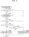
- FIG. 4 is a flowchart illustrating a spring characteristic switching routine of this embodiment.
- step S207 is added to a process (S201 - S206) corresponding to the process of steps S101 - S106 of the spring characteristic switching routine of the first embodiment.
- the electronic control unit 31 makes respective determinations as follows in steps S201 - S204 of the spring characteristic switching routine of FIG. 4 . Specifically, the electronic control unit 31 determines whether the ignition switch 37 has been turned ON (S201), determines whether a predetermined length of time has elapsed after completion of start-up (S202), determines whether the engine speed NE is lower than a criterial value HR (S203), and determines whether engine torque Trq is equal to or larger than a criterial value HT (S204).
- step S204 If it is determined in step S204 that the engine torque Trq is equal to or larger than the criterial value HT, the electronic control unit 31 sets the spring characteristics of the engine mount 3 to the first spring characteristics, by opening he VSV 21 in step S205. If a negative decision (NO) is made in any of steps S201 - S203, the electronic control unit 31 sets the spring characteristics of the engine mount 3 to the second spring characteristics, by closing the VSV 21 in step S206.
- step S207 the electronic control unit 31 determines whether the vehicle speed SPD is lower than a criterial value HS.
- the criterial value HS is set based on a threshold value C (in this embodiment, 10 km/h) and a hysteresis width C1.
- the criterial value HS is set to the threshold value C while the vehicle speed SPD is decreasing, and is set to a value (C-C1) obtained by subtracting the hysteresis width C1 from the threshold value C while the vehicle speed SPD is increasing. For example, a value of 5 km/h is used as the hysteresis width C1.
- step S207 If it is determined in step S207 that the vehicle speed SPD is lower than the criterial value HS, the control proceeds to step S205. If it is determined in step S207 that the vehicle speed SPD is equal to or higher than the criterial value HS, the control proceeds to step S206. After one of these steps S205 and S206 is executed, the electronic control unit 31 once finishes the spring characteristic switching routine. With step S207 thus added to the routine, even when the engine speed NE is lower than the criterial value HR (S203: YES), and the engine torque Trq is smaller than the criterial value HT (S204: NO), the VSV 21 is opened and the spring characteristics of the engine mount 3 are switched to the first spring characteristics (S205) if the vehicle speed SPD is lower than the criterial value HS.
- the electronic control unit 31 switches the spring characteristics of the engine mount 3 to the first spring characteristics, under the condition that the vehicle speed SPD is lower than the criterial value HS.
- the vehicle speed SPD is low, vibration is less likely to be transmitted from the road surface to the vehicle 1 side, and resonance is less likely to occur between the vibration transmitted from the road surface to the vehicle 1 side and the vibration of the engine 2; therefore, the passenger is not significantly affected by the resonance.
- the vehicle speed SPD when the vehicle speed SPD is low, it is preferable to place a higher priority on reduction of engine vibration transmitted to the vehicle 1 side, than damping of vibration transmitted from the road surface to the vehicle 1 side.
- the vehicle speed SPD when the vehicle speed SPD is low, it is preferable to switch the spring characteristics of the engine mount 3 to the first spring characteristics, even under the situation where the second spring characteristics are normally selected as the spring characteristics of the engine mount 3, namely, under the situation where the engine speed NE is lower than the criterial value HR, and the engine torque Trq is smaller than the criterial value HT. This can be achieved according to the second embodiment.
- VSV 21 is not necessarily required to operate using a negative pressure, but may operate electrically, rather than using the negative pressure.
- threshold value A While 1200 rpm is employed as an example of the threshold value A, this value may be changed as needed to another different value. While 40 N/m is employed as an example of the threshold value B, this value may be changed as needed to another different value.
- the hysteresis widths A1, B1, C1 are not necessarily required to be set. Namely, the hysteresis widths A1, B1, C1 may be set to "0", thereby to be eliminated.
Landscapes
- Engineering & Computer Science (AREA)
- Mechanical Engineering (AREA)
- Chemical & Material Sciences (AREA)
- Combustion & Propulsion (AREA)
- Transportation (AREA)
- General Engineering & Computer Science (AREA)
- Physics & Mathematics (AREA)
- Acoustics & Sound (AREA)
- Aviation & Aerospace Engineering (AREA)
- Arrangement Or Mounting Of Propulsion Units For Vehicles (AREA)
- Vibration Prevention Devices (AREA)
Abstract
Description
- The invention relates to a suspension system for an engine of a vehicle.
- A suspension system for an engine in a vehicle includes an engine mount that supports the engine on the vehicle. The engine mount has the function of curbing transmission of engine vibration to the vehicle side, and damping vibration transmitted from a road surface to the vehicle. In the engine mount, a small spring constant of the engine mount improves the capability of curbing transmission of engine vibration to the vehicle side. On the other hand, in the engine mount, a high damping coefficient of the engine mount improves the capability of damping vibration transmitted from the road surface to the vehicle.
-
Japanese Patent Application Publication No. 2011-80492 JP 2011-80492 A -
FIG. 5 shows an example of change of the spring constant k and change of the damping coefficient c with change in the frequency of engine vibration when the engine mount is tuned to selected spring characteristics (which will be called "first spring characteristics"). The frequency of engine vibration increases as the engine speed increases. When the engine mount is tuned to the first spring characteristics, the frequency at which the spring constant k is maximized and the frequency at which the damping coefficient c is maximized are close to each other, and these frequencies are relatively large values. -
FIG. 6 shows an example of change of the spring constant k and change of the damping coefficient c with change in the frequency of engine vibration when the engine mount is tuned to selected spring characteristics (which will be called "second spring characteristics") that are different from the first spring characteristics. When the engine mount is tuned to the second spring characteristics, the frequency at which the spring constant k is maximized and the frequency at which the damping coefficient c is maximized are close to each other, and these frequencies are relatively small values. - In the meantime, a passenger of the vehicle may feel uncomfortable when engine vibration is transmitted to the vehicle side. Accordingly, in order to curb transmission of engine vibration to the vehicle side as much as possible, it is desirable to enhance the capability of curbing transmission of engine vibration to the vehicle side in the engine mount over an entire change region of the engine speed, in other words, to reduce the spring constant k of the engine mount over the entire change region of the engine speed.
- To achieve the above condition, it may be considered to employ a technology as disclosed in
Japanese Patent Application Publication No. 5-139165 JP 5-139165 A FIG. 5 ) when the engine speed is low (e.g., lower than 1200 rpm), whereas the spring characteristics of the engine mount are switched to the second spring characteristics (FIG. 6 ) when the engine speed is high (e.g., equal to or higher than 1200 rpm). - By switching the spring characteristics of the engine mount according to the engine speed, it is possible to reduce the spring constant k of the engine mount over the entire change region of the engine speed, and enhance the capability of curbing transmission of engine vibration to the vehicle side in the engine mount. Accordingly, engine vibration is less likely or unlikely to be transmitted to the vehicle side, over the entire change region of the engine speed, and the passenger of the vehicle is less likely or unlikely to feel uncomfortable due to the transmission of the vibration.
- The invention also relates to a vehicle that comprises such an engine mount.
- In the meantime, in a region in which the engine speed is low, namely, in a region in which the frequency of engine vibration is low, there is a frequency region (in this example, 7 - 20Hz) in which vibration transmitted from a road surface to the vehicle side during traveling of the vehicle resonates with vibration of the engine itself. If such a resonance occurs, the vehicle shakes largely, and a passenger of the vehicle feels uncomfortable. In order to suppress such an uncomfortable feeling of the passenger caused by the resonance, it is useful to increase the damping coefficient c of the engine mount, and enhance the performance of the engine mount, i.e., its capability of damping vibration transmitted from the road surface to the vehicle.
- However, when the engine speed is low, the spring characteristics of the engine mount are switched to the first spring characteristics (
FIG. 5 ), so as to make it less likely or unlikely for the passenger to feel uncomfortable due to transmission of engine vibration to the vehicle side. Therefore, the damping coefficient c of the engine mount is reduced in the frequency region in which the resonance occurs. Namely, the engine mount's capability of damping vibration transmitted from the road surface to the vehicle is reduced. Accordingly, when the engine speed is low, the resonance occurs in the above-indicated frequency region, and the passenger of the vehicle feel uncomfortable. Thus, there is some room for further improvement in terms of suppression of the uncomfortable feeling of the passenger caused by the resonance. - The invention provides a suspension system for an engine, which makes it less likely or unlikely for passengers to feel uncomfortable due to resonance of vibration transmitted from a road surface to the vehicle when the engine speed is low, and vibration of the engine.
- A suspension system for an engine according to one aspect of the invention includes an engine mount and an electronic control unit. The engine mount is configured to support the engine on a vehicle. The engine mount has spring characteristics that are switchable between first spring characteristics and second spring characteristics. The second spring characteristics provide a larger damping coefficient and a larger spring constant than the first spring characteristics when a rotational speed of the engine is lower than a predetermined rotational speed. The electronic control unit is configured to switch the spring characteristics of the engine mount to the first spring characteristics when the rotational speed of the engine is lower than the predetermined rotational speed, and torque of the engine is equal to or larger than a predetermine torque. The electronic control unit is configured to switch the spring characteristics of the engine mount to the second spring characteristics when the rotational speed of the engine is lower than the predetermined rotational speed, and the torque of the engine is smaller than the predetermined torque.
- When the engine speed is lower than the predetermined rotational speed, engine vibration increases as torque of the engine is larger. Thus, in order to prevent the passenger of the vehicle from feeling uncomfortable due to the engine vibration transmitted to the vehicle side, when the engine speed is lower than the predetermined rotational speed, and the torque of the engine is equal to or larger than the predetermined torque, the spring characteristics of the engine mount are switched to the first spring characteristics so as to curb transmission of engine vibration to the vehicle side.
- On the other hand, when the engine speed is lower than the predetermined rotational speed, engine vibration is reduced as torque of the engine is smaller; therefore, the passenger of the vehicle does not feel uncomfortable even if the engine vibration is transmitted to the vehicle side. In view of this fact, when the engine speed is lower than the predetermined rotational speed, and the torque of the engine is smaller than the predetermined torque, a greater emphasis is placed on damping of vibration transmitted from the road surface to the vehicle side, than reduction of engine vibration transmitted to the vehicle side, and the spring characteristics of the engine mount are switched to the second spring characteristics.
- There is a frequency region in which vibration transmitted from the road surface to the vehicle side during traveling of the vehicle resonates with vibration of the engine itself, in a region where the engine speed is lower than the predetermined rotational speed, namely, in a region where the frequency of engine vibration is low. Nonetheless, the spring characteristics of the engine mount are switched to the second spring characteristics as described above, so that the engine mount provides a large damping coefficient in the region where the frequency is low. Thus, if the damping coefficient of the engine mount is increased in the low frequency region, the engine mount can effectively suppress resonance of the vibration transmitted from the road surface to the vehicle, and the vibration of the engine itself, and the passenger is less likely or unlikely to feel uncomfortable due to the resonance.
- In the suspension system for the engine according to the above aspect of the invention, the electronic control unit may be configured to switch the spring characteristics of the engine mount to the first spring characteristics when the rotational speed of the engine is lower than the predetermined rotational speed, the torque of the engine is smaller than the predetermined torque, and a traveling speed of the vehicle is lower than a predetermined vehicle speed.
- When the traveling speed of the vehicle is low, vibration is less likely to be transmitted from the road surface to the vehicle side, and resonance between the vibration and vibration of the engine is less likely to occur; therefore, the passenger is not significantly affected by the resonance. Accordingly, when the traveling speed of the vehicle is lower than the predetermined vehicle speed, it is preferable to place a higher priority on reduction of engine vibration transmitted to the vehicle side, than damping of vibration transmitted from the road surface to the vehicle side. In other words, when the traveling speed of the vehicle is lower than the predetermined vehicle speed, it is preferable to switch the spring characteristics of the engine mount to the first spring characteristics, even under the situation where the second spring characteristics are normally selected as the spring characteristics of the engine mount, namely, under the situation where the engine speed is lower than the predetermined rotational speed, and the torque of the engine is smaller than the predetermined torque. According to the above-described arrangement, the spring characteristics can be switched in this manner.
- Features, advantages, and technical and industrial significance of exemplary embodiments of the invention will be described below with reference to the accompanying drawings, in which like numerals denote like elements, and wherein:
-
FIG. 1 a schematic view showing the overall configuration of a suspension system for an engine; -
FIG. 2 is a cross-sectional view showing the internal structure of an engine mount in the system ofFIG. 1 ; -
FIG. 3 is a flowchart illustrating a procedure of switching spring characteristics of the engine mount; -
FIG. 4 is a flowchart illustrating a procedure of switching spring characteristics of the engine mount; -
FIG. 5 is a graph indicating changes in the spring constant k and damping coefficient c of the engine mount having first spring characteristics, relative to change of the frequency of engine vibration; and -
FIG. 6 is a graph indicating changes in the spring constant k and damping coefficient c of the engine mount having second spring characteristics, relative to change of the frequency of engine vibration. - Referring to
FIG. 1 through FIG. 3 , a suspension system for an engine in a vehicle according to a first embodiment of the invention will be described. - The suspension system shown in
FIG. 1 includesengine mounts 3 that support anengine 2 on avehicle 1. Theengine mounts 3 have the function of curbing transmission of vibration of the engine 2 (which will be called "engine vibration") to thevehicle 1 side during operation of theengine 2, and damping vibration transmitted from a road surface to thevehicle 1 during traveling of thevehicle 1. Theengine mount 3 has a higher capability of curbing transmission of engine vibration to thevehicle 1 side as the spring constant k of theengine mount 3 is smaller. On the other hand, theengine mount 3 has a higher capability of damping vibration transmitted from the road surface to the vehicle as the damping coefficient c of theengine mount 3 is larger. -
FIG. 2 is a cross-sectional view showing the internal structure of theengine mount 3. Theengine mount 3 includes a generally cylindricalmain body case 4 that is open at its upper and lower ends as viewed inFIG. 2 , alower cover 5 that closes the lower end of themain body case 4, and arubber base 6 fixed to an upper portion of an inner circumferential surface of themain body case 4. Themain body case 4 and thelower cover 5 are fixed to thevehicle 1. On the other hand, a mountingbracket 7 is fixed to therubber base 6. The mountingbracket 7 protrudes from the upper end of themain body case 4, and is fixed to theengine 2. Accordingly, theengine mount 3, when it is supported on thevehicle 1, receives a load from theengine 2. - A
lower diaphragm 8 is provided in a bottom portion (lower portion inFIG. 2 ) of thelower cover 5. The space between thelower diaphragm 8 and therubber base 6 in the interior of themain body case 4 and thelower cover 5 is divided by anintermediate body 9 into anupper liquid chamber 10 and alower liquid chamber 11. Theintermediate body 9 is a rigid body that is fixed to an upper portion of an inner circumferential surface of thelower cover 5. The upperliquid chamber 10 and thelower liquid chamber 11 are filled with liquid. Afirst orifice 12 that communicates with the upperliquid chamber 10 and thelower liquid chamber 11 is formed in an outer circumferential portion of theintermediate body 9. When the relative positions of thevehicle 1 and theengine 2 change due to vibration of at least one of thevehicle 1 and theengine 2, therubber base 6 deforms according to the change in the positions, and the liquid flows between the upperliquid chamber 10 and thelower liquid chamber 11 via thefirst orifice 12, due to the deformation of therubber base 6. - The interior of the
intermediate body 9 is a hollow and forms a chamber, and said chamber is divided by an intermediate diaphragm 13 into an intermediate liquid chamber 14 and anair chamber 15. The intermediate liquid chamber 14 communicates with the upperliquid chamber 10 via asecond orifice 16 formed in theintermediate body 9, and is filled with liquid, like the upperliquid chamber 10. On the other hand, theair chamber 15 is connected to a feed/discharge passage 17 formed in theintermediate body 9,lower cover 5, and themain body case 4. If air is drawn from theair chamber 15 through the feed/discharge passage 17, and the pressure in theair chamber 15 is reduced to a value that is lower by a given amount than the atmospheric pressure, the intermediate diaphragm 13 is deformed as indicated by a two-dot chain line inFIG. 2 , based on a difference between the pressure in theair chamber 15 and the pressure in the intermediate liquid chamber 14, so as to reduce the volume of the air chamber 15 (or increase the volume of the intermediate chamber 14). - If the air stops being drawn from the
air chamber 15 through the feed/discharge passage 17, and the pressure in theair chamber 15 is increased to a level around the atmospheric pressure, the difference between the pressure in theair chamber 15 and the pressure in the intermediate liquid chamber 14 is reduced, and the intermediate diaphragm 13 returns to the original position as indicated by a solid line inFIG. 2 , due to the elasticity of the intermediate diaphragm 13 itself. When the intermediate diaphragm 13 is located at the position as indicated by the solid line, an end portion of thesecond orifice 16 which faces the intermediate liquid chamber 14 is closed or blocked by the intermediate diaphragm 13. On the other hand, when the intermediate diaphragm 13 is displaced or moved to the position as indicated by the two-dot chain line, the end portion of thesecond orifice 16 which faces the intermediate liquid chamber 14 is opened, through the displacement of the intermediate diaphragm 13. - In the condition where the end portion of the
second orifice 16 facing the intermediate liquid chamber 14 is closed by the intermediate diaphragm 13, namely, in the condition as indicated by the solid line inFIG. 2 , the liquid does not flow between the upperliquid chamber 10 and the intermediate liquid chamber 14 via thesecond orifice 16, even if therubber base 6 deforms due to vibration of at least one of thevehicle 1 and theengine 2. On the other hand, in the condition where the end portion of thesecond orifice 16 facing the intermediate liquid chamber 14 is open to the chamber 14, namely, in the condition where the intermediate diaphragm 13 is displaced as indicated by the two-dot chain line inFIG. 2 , the liquid flows between the upperliquid chamber 10 and the intermediate liquid chamber 14 via thesecond orifice 16 when therubber base 6 deforms due to vibration of at least one of thevehicle 1 and theengine 2. - Accordingly, the spring characteristics of the
engine mount 3 are switched, depending on the presence or absence of flow of the liquid through thesecond orifice 16, between the time when the intermediate diaphragm 13 is placed in the condition as indicated by the solid line inFIG. 2 , with the air being kept from being drawn from theair chamber 15, and the time when the intermediate diaphragm 13 is displaced as indicated by the two-dot chain line inFIG. 2 , with the air being drawn from theair chamber 15. - In this embodiment, components of the
engine mount 3 such as thefirst orifice 12 andlower diaphragm 8 are tuned so that, when the intermediate diaphragm 13 is placed in the condition as indicated by the solid line inFIG. 2 , with the air being kept from being drawn from theair chamber 15, theengine mount 3 provides the above-indicated second spring characteristics with which the frequencies of engine vibration (engine speeds) at which the spring constant K and the damping coefficient c reach their maximum values are low (7 - 20 Hz), as shown inFIG. 6 . Also, thesecond orifice 16 and the intermediate diaphragm 13 of theengine mount 3 are tuned so that, when the intermediate diaphragm 13 is displaced as indicated by the two-dot chain line inFIG. 2 , with the air being drawn from theair chamber 15, theengine mount 3 provides the above-indicated first spring characteristics with which the frequencies of engine vibration (engine speeds) at which the spring constant K and the damping coefficient c reach their maximum values are high (around 1200 rpm). - When the spring characteristics of the
engine mount 3 are set to the first spring characteristics, namely, when the intermediate diaphragm 13 is displaced as indicated by the two-dot chain line inFIG. 2 , the spring constant k and damping coefficient c of theengine mount 3 change as indicated inFIG. 5 as the frequency of engine vibration becomes higher with increase of the engine speed. As is understood fromFIG. 5 , when the spring characteristics of theengine mount 3 are set to the first spring characteristics, the frequency at which the spring constant k is maximized and the frequency at which the damping coefficient c is maximized are close to each other, and these frequencies are higher than those of the second spring characteristics. - When the spring characteristics of the
engine mount 3 are set to the second spring characteristics, namely, when the intermediate diaphragm 13 is placed in the position as indicated by the solid line ofFIG. 2 , the spring constant k and damping coefficient c of theengine mount 3 change as indicated inFIG. 6 as the frequency of engine vibration becomes higher with increase of the engine speed. As is understood fromFIG. 6 , when the spring characteristics of theengine mount 3 are set to the second spring characteristics, the frequency at which the spring constant k is maximized and the frequency at which the damping coefficient c is maximized are close to each other, and these frequencies are lower than those of the first spring characteristics. - Next, the structure for drawing air from the
air chamber 15 of theengine mount 3 will be described. As shown inFIG. 1 , the suspension system includes anegative pressure tank 19 connected to the downstream side of a throttle valve in an intake passage of theengine 2 via apipe 18. If a negative pressure is developed on the downstream side of the throttle valve in the intake passage through a closing action of the throttle valve, the air in thenegative pressure tank 19 is drawn into the intake passage through thepipe 18, based on the negative pressure, so that the pressure in thenegative pressure tank 19 becomes lower than the atmospheric pressure. Thenegative pressure tank 19 is arranged to hold the interior of thetank 19 in a negative-pressure condition even when the throttle valve is open. - The
negative pressure tank 19 is connected to the feed/discharge passage 17 of each of the engine mounts 3 via a feed/discharge pipe 20. Also, a vacuum switching valve (VSV) 21 is provided in the feed/discharge pipe 20. TheVSV 21 is operable to be opened and closed so as to communicate the feed/discharge passage 17 of theengine mount 3 with thenegative pressure tank 19 and disconnect thepassage 17 from thetank 19. When theVSV 21 is opened, the feed/discharge passage 17 communicates with thenegative pressure tank 19, and the air is drawn from theair chamber 15 of theengine mount 3 via the feed/discharge passage 17 based on the negative pressure in thenegative pressure tank 19. When theVSV 21 is closed, the feed/discharge passage 17 and thenegative pressure tank 19 are disconnected from each other, and the air is inhibited from being drawn from theair chamber 15 via the feed/discharge passage 17 under the negative pressure in thenegative pressure tank 19. - Accordingly, the spring characteristics of the
engine mount 3 are set to the second spring characteristics in the condition where theVSV 21 is closed and the air is inhibited from being drawn from theair chamber 15, whereas the spring characteristics of theengine mount 3 are set to the first spring characteristics in the condition where theVSV 21 is opened and the air is drawn from theair chamber 15. Thepipe 18,negative pressure tank 19, feed/discharge pipes 20, and theVSVs 21 provided in the suspension system function as a switching unit for switching the spring characteristics of the engine mounts 3 between the first spring characteristics and the second spring characteristics. - Next, the electric configuration of the suspension system will be described. The suspension system includes an
electronic control unit 31 that performs various operation controls of theengine 2. Theelectronic control unit 31 is provide with CPU that performs various computations concerned with the above-mentioned various operation controls, ROM in which programs and data needed for the controls are stored, RAM in which computation results of the CPU, etc. are temporarily stored, input and output ports for receiving signals from the outside and transmitting signals to the outside, and so forth. - Various sensors for which examples will be detailed hereafter are connected to the input port of the
electronic control unit 31. The sensors include an accelerator position sensor 32 that detects the accelerator operation amount, and a throttle position sensor 33 that detects the throttle opening. - The sensors also include an air flow meter 34 that detects the intake air amount of the
engine 2, a rotational speed sensor 35 that detects the rotational speed of the engine 2 (the engine speed NE), a vehicle speed sensor 36 that detects the traveling speed of the vehicle 1 (vehicle speed SPD), and anignition switch 37 operated by the driver. - To the output port of the
electronic control unit 31 are connected drive circuits of various equipment or devices, such as the throttle valve, injectors, and ignition plugs, for operating theengine 2, and drive circuits of theVSVs 21. - The
electronic control unit 31 starts theengine 2 when theignition switch 37 is manually turned on by the driver, and stops theengine 2 when theignition switch 37 is manually turned off by the driver. Also, theelectronic control unit 31 grasps operating conditions required of theengine 2 and the actual operating conditions of theengine 2, based on signals received from the above-indicated various sensors, and outputs command signals to various drive circuits connected to the output port, based on the required and actual operating conditions. In this manner, theelectronic control unit 31 performs various operation controls of theengine 2, including throttle opening control, fuel injection control, and ignition timing control of theengine 2. - Next, the control for switching the spring characteristics of the
engine mount 3 between the first spring characteristics and the second spring characteristics will be described.FIG. 3 is a flowchart illustrating a spring characteristic switching routine for performing the above switching control. The spring characteristic switching routine is periodically executed as an interrupt routine at given time intervals. Theelectronic control unit 31 functions as a controller that performs the switching control when it executes the spring characteristic switching routine. - In step S101 of the routine of
FIG. 3 , theelectronic control unit 31 determines whether theignition switch 37 has been turned ON by the driver. If an affirmative decision (YES) is made in step S101, the control proceeds to step S102. In step S102, theelectronic control unit 31 determines whether a predetermined length of time (e.g., 1 sec.) has elapsed after the start of theengine 2, namely after the start of self-sustained operation of theengine 2. If an affirmative decision (YES) is made in step S102, the control proceeds to step S103. - In step S103, the
electronic control unit 31 determines whether the engine speed NE is lower than a criterial value HR. The criterial value HR is set based on a threshold value A (in this embodiment, 1200 rpm) and a hysteresis width A1. The criterial value HR is set to the threshold value A while the engine speed NE is increasing, and is set to a value (A-A1) obtained by subtracting the hysteresis width A1 from the threshold value A while the engine speed NE is decreasing. For example, a value of 50 rpm is used as the hysteresis width A1. - If it is determined in step S103 that the engine speed NE is lower than the criterial value HR, the control proceeds to step S104. In step S104, the
electronic control unit 31 determines whether engine torque Trq is equal to or larger than a criterial value HT. The criterial value HT is set based on a threshold value B (in this embodiment, 40N/m) and ahysteresis width B 1. The criterial value HT is set to the threshold value B while engine torque Trq is decreasing, and is set to a value (B+B1) obtained by adding the hysteresis width B1 to the threshold value B while the engine torque Trq is increasing. For example, a value of 10 N/m is used as the hysteresis width B1. - The engine torque Trq used in step S104 can be obtained based on the engine load factor that represents the ratio of the engine load to the full load of the
engine 2. Also, the engine load factor is obtained based on a parameter relating to the intake air amount of theengine 2, and the engine speed N. Examples of the parameter relating to the intake air amount of theengine 2 include the accelerator operation amount detected by the accelerator position sensor 32, throttle opening detected by the throttle position sensor 33, and the actual measurement value of the intake air amount detected by the air flow meter 34. - When it is determined in step S104 that the engine torque Trq is equal to or larger than the criterial value HT, the control proceeds to step S105. In step S105, the
electronic control unit 31 causes theVSV 21 to be opened so as to set the spring characteristics of theengine mount 3 to the first spring characteristics, and then once finish the spring characteristic switching routine. On the other hand, if it is determined in step S104 that the engine torque Trq is smaller than the criterial value HT, the control proceeds to step S106. In step S106, theelectronic control unit 31 causes theVSV 21 to be closed so as to set the spring characteristics of theengine mount 3 to the second spring characteristics, and then once finish the spring characteristic switching routine. - In the case where a negative decision (NO) is made in any of steps S101 - S103, too, the control proceeds to step S106. Accordingly, when the engine speed NE is equal to or higher than the criterial value HR (S103: NO), the
VSV 21 is opened in step S106, so that the spring characteristics of theengine mount 3 are set to the second spring characteristics. - Next, the operation of the suspension system of the
engine 2 will be described. In order to prevent a passenger from feeling uncomfortable because of engine vibration transmitted to thevehicle 1 side, it is desirable to enhance the NV (noise and vibration) performance of theengine mount 3 over the entire change region of the engine speed NE, in other words, reduce the spring constant k of theengine mount 3 over the entire change region of the engine speed NE. To achieve this, it may be considered to switch the spring characteristics of theengine mount 3 to the first spring characteristics (FIG. 5 ) when the engine speed NE is lower than the criterial value HR, and switch the spring characteristics of theengine mount 3 to the second spring characteristics (FIG. 6 ) when the engine speed NE is equal to or higher than the criterial value HR. - However, in a region where the engine speed NE is lower than the criterial value HR, namely, in a region where the frequency of engine vibration is low, there is a frequency region (7 - 20 Hz in the example of
FIGS. 5 and 6 ) in which the vibration transmitted from a road surface to thevehicle 1 side resonates with vibration of theengine 2 itself during traveling of thevehicle 1. In order to make it less likely or unlikely for the passenger of thevehicle 1 to feel uncomfortable due to occurrence of the resonance, it is useful to increase the damping coefficient c of theengine mount 3, namely, to enhance the performance of theengine mount 3 or its capability of damping vibration transmitted from the road surface to thevehicle 1. - However, in the case where the spring characteristics of the
engine mount 3 is set to the first spring characteristics as described above when the engine speed NE is lower than the criterial value HR, the damping coefficient c of theengine mount 3 is reduced in the frequency region in which the resonance occurs. Namely, theengine mount 3 has a reduced capability of damping vibration transmitted from the road surface to thevehicle 1. Therefore, when the engine speed NE is low, i.e., lower than the criterial value HR, resonance may occur in the above-mentioned frequency region (which will be called "resonance frequency region"), and the passenger of thevehicle 1 may feel uncomfortable due to the resonance. - To solve the above problem, the
electronic control unit 31 switches the spring characteristics of theengine mount 3 between the first spring characteristics and the second spring characteristics, according to the engine torque Trq, when the engine speed NE is lower than the criterial value HR. - More specifically, when the engine speed NE is lower than the criterial value HR, and the engine torque Trq is equal to or larger than the criterial value HT, the
electronic control unit 31 causes theVSV 21 to be opened so as to switch the spring characteristics of theengine mount 3 to the first spring characteristics. Also, when the engine speed NE is lower than the criterial value HR, and the engine torque Trq is smaller than the criterial value HT, theelectronic control unit 31 causes theVSV 21 to be closed so as to switch the spring characteristics of theengine mount 3 to the second spring characteristics with which the damping coefficient c and the spring constant k are larger than those of the first spring characteristics. - When the engine speed NE is lower than the criterial value HR, engine vibration increases as the engine torque Trq is larger. In order to prevent the passenger of the
vehicle 1 from feeling uncomfortable due to the engine vibration transmitted to thevehicle 1 side at this time, theelectronic control unit 31 switches the spring characteristics of theengine mount 3 to the first spring characteristics so as to curb transmission of the engine vibration to thevehicle 1 side, when the engine speed NE is lower than the criterial value HR, and the engine torque Trq is equal to or larger than the criterial value HT. - On the other hand, when the engine speed NE is lower than the criterial value HR, engine vibration is reduced as the engine torque Trq is smaller; therefore, the passenger of the
vehicle 1 does not feel uncomfortable even if the engine vibration is transmitted to thevehicle 1 side. In view of this fact, when the engine speed NE is lower than the criterial value HR, and the engine torque Trq is smaller than the criterial value HT, the spring characteristics of theengine mount 3 are switched to the second spring characteristics, with a greater emphasis placed on damping of vibration transmitted from a road surface to thevehicle 1 side, than reducing engine vibration transmitted to thevehicle 1 side. - If the spring characteristics of the
engine mount 3 are switched to the second spring characteristics (FIG. 6 ) according to the engine torque Trq as described above, in the region where the engine speed NE is lower than the criterial value HR, namely, in the region where the frequency of engine vibration is low, the damping coefficient c of theengine mount 3 is increased in the above-indicated resonance frequency region (7 - 20 Hz in the example ofFIG. 6 ). Thus, it is possible for theengine mount 3 to effectively reduce resonance of the vibration transmitted from the road surface to thevehicle 1 and the vibration of theengine 2 itself, and thereby make it less likely or unlikely for the passenger to feel uncomfortable due to the resonance. - According to this embodiment as described above in detail, the following effect can be obtained. (1) The passenger is less likely or unlikely to feel uncomfortable because of resonance of vibration transmitted from the road surface to the
vehicle 1 and vibration of theengine 2, in the region where the engine speed NE is lower than the criterial value HR. - Next, a second embodiment of the invention will be described with reference to
FIG. 4. FIG. 4 is a flowchart illustrating a spring characteristic switching routine of this embodiment. In this spring characteristic switching routine, step S207 is added to a process (S201 - S206) corresponding to the process of steps S101 - S106 of the spring characteristic switching routine of the first embodiment. - The
electronic control unit 31 makes respective determinations as follows in steps S201 - S204 of the spring characteristic switching routine ofFIG. 4 . Specifically, theelectronic control unit 31 determines whether theignition switch 37 has been turned ON (S201), determines whether a predetermined length of time has elapsed after completion of start-up (S202), determines whether the engine speed NE is lower than a criterial value HR (S203), and determines whether engine torque Trq is equal to or larger than a criterial value HT (S204). - If it is determined in step S204 that the engine torque Trq is equal to or larger than the criterial value HT, the
electronic control unit 31 sets the spring characteristics of theengine mount 3 to the first spring characteristics, by opening he VSV 21 in step S205. If a negative decision (NO) is made in any of steps S201 - S203, theelectronic control unit 31 sets the spring characteristics of theengine mount 3 to the second spring characteristics, by closing theVSV 21 in step S206. - If a negative decision (NO) is made in step S204, namely, when it is determined that the engine torque Trq is smaller than the criterial value HT, the control proceeds to step S207. In step S207, the
electronic control unit 31 determines whether the vehicle speed SPD is lower than a criterial value HS. The criterial value HS is set based on a threshold value C (in this embodiment, 10 km/h) and a hysteresis width C1. The criterial value HS is set to the threshold value C while the vehicle speed SPD is decreasing, and is set to a value (C-C1) obtained by subtracting the hysteresis width C1 from the threshold value C while the vehicle speed SPD is increasing. For example, a value of 5 km/h is used as the hysteresis width C1. - If it is determined in step S207 that the vehicle speed SPD is lower than the criterial value HS, the control proceeds to step S205. If it is determined in step S207 that the vehicle speed SPD is equal to or higher than the criterial value HS, the control proceeds to step S206. After one of these steps S205 and S206 is executed, the
electronic control unit 31 once finishes the spring characteristic switching routine. With step S207 thus added to the routine, even when the engine speed NE is lower than the criterial value HR (S203: YES), and the engine torque Trq is smaller than the criterial value HT (S204: NO), theVSV 21 is opened and the spring characteristics of theengine mount 3 are switched to the first spring characteristics (S205) if the vehicle speed SPD is lower than the criterial value HS. - According to this embodiment, the following effect can be obtained, in addition to the effect of the first embodiment. (2) When the engine speed NE is lower than the criterial value HR, and the engine torque Trq is smaller than the criterial value HT, the
electronic control unit 31 switches the spring characteristics of theengine mount 3 to the first spring characteristics, under the condition that the vehicle speed SPD is lower than the criterial value HS. When the vehicle speed SPD is low, vibration is less likely to be transmitted from the road surface to thevehicle 1 side, and resonance is less likely to occur between the vibration transmitted from the road surface to thevehicle 1 side and the vibration of theengine 2; therefore, the passenger is not significantly affected by the resonance. Accordingly, when the vehicle speed SPD is low, it is preferable to place a higher priority on reduction of engine vibration transmitted to thevehicle 1 side, than damping of vibration transmitted from the road surface to thevehicle 1 side. In other words, when the vehicle speed SPD is low, it is preferable to switch the spring characteristics of theengine mount 3 to the first spring characteristics, even under the situation where the second spring characteristics are normally selected as the spring characteristics of theengine mount 3, namely, under the situation where the engine speed NE is lower than the criterial value HR, and the engine torque Trq is smaller than the criterial value HT. This can be achieved according to the second embodiment. - Each of the above-described embodiments may be modified as follows, for example. The
VSV 21 is not necessarily required to operate using a negative pressure, but may operate electrically, rather than using the negative pressure. - While 1200 rpm is employed as an example of the threshold value A, this value may be changed as needed to another different value. While 40 N/m is employed as an example of the threshold value B, this value may be changed as needed to another different value.
- While 10 km/h is employed as an example of the threshold value C, this value may be changed as needed to another different value. While 50 rpm is employed as an example of the hysteresis width A1, this value may be changed as needed to another different value.
- While 10 N/m is employed as an example of the hysteresis width B1, this value may be changed as needed to another different value. While 5 km/h is employed as an example of the hysteresis width C1, this value may be changed as needed to another different value.
- The hysteresis widths A1, B1, C1 are not necessarily required to be set. Namely, the hysteresis widths A1, B1, C1 may be set to "0", thereby to be eliminated.
Claims (5)
- A suspension system for an engine, characterized in that it comprises:an engine mount (3) configured to support an engine of a vehicle, the engine mount (3) having spring characteristics that are switchable between first spring characteristics and second spring characteristics, the engine mount (3) being configured so that the second spring characteristics provide a larger damping coefficient and a larger spring constant than the first spring characteristics when a rotational speed of the engine is lower than a predetermined rotational speed; andan electronic control unit (31) configured to switch the spring characteristics of the engine mount (3) to the first spring characteristics when the rotational speed of the engine is lower than the predetermined rotational speed, and torque of the engine is equal to or larger than a predetermine torque, the electronic control unit (31) being configured to switch the spring characteristics of the engine mount (3) to the second spring characteristics when the rotational speed of the engine is lower than the predetermined rotational speed, and the torque of the engine is smaller than the predetermined torque.
- The suspension system according to claim 1, wherein
the electronic control unit (31) is configured to switch the spring characteristics of the engine mount (3) to the first spring characteristics when the rotational speed of the engine is lower than the predetermined rotational speed, the torque of the engine is smaller than the predetermined torque, and a traveling speed of the vehicle is lower than a predetermined vehicle speed. - The suspension system according to claim 1 or 2, wherein the engine mount (3) comprises a main body case (4) with an upper liquid chamber (10) and an intermediate body (9), said intermediate body (9) comprising an inner chamber divided by a diaphragm (13) into an intermediate liquid chamber (14) and an air chamber (15),
wherein the intermediate liquid chamber (14) is connected to the upper liquid chamber (10) through a second orifice (16), the intermediate liquid chamber (14) and the upper liquid chamber (10) being filled with the same liquid,
wherein the air chamber (15) is connected to a feed/discharge channel (20), configured to define the pressure within the air chamber (15), so as to switch the diaphragm (13) between:- a first spring configuration where the diaphragm (13) is such that the intermediate liquid chamber (14) communicates with the upper liquid chamber (10) through the second orifice (16),- a second spring configuration where the diaphragm (13) closes the second orifice (16). - The suspension system according to claim 3, wherein the engine mount (3) further comprises a lower liquid chamber (11) within the main body case (4); separated from the upper liquid chamber (10) by an intermediate body (9), and that communicate with the upper liquid chamber (10) through a first orifice (12),
wherein the upper liquid chamber (10) and the lower liquid chamber (11) being filled with the same liquid. - A vehicle comprising an engine and a suspension system for the engine according to any one of claims 1 to 4.
Applications Claiming Priority (1)
| Application Number | Priority Date | Filing Date | Title |
|---|---|---|---|
| JP2015027649A JP6252794B2 (en) | 2015-02-16 | 2015-02-16 | Engine suspension |
Publications (2)
| Publication Number | Publication Date |
|---|---|
| EP3056368A1 true EP3056368A1 (en) | 2016-08-17 |
| EP3056368B1 EP3056368B1 (en) | 2017-08-16 |
Family
ID=55409699
Family Applications (1)
| Application Number | Title | Priority Date | Filing Date |
|---|---|---|---|
| EP16155133.8A Not-in-force EP3056368B1 (en) | 2015-02-16 | 2016-02-11 | Engine suspension system |
Country Status (4)
| Country | Link |
|---|---|
| US (1) | US10093162B2 (en) |
| EP (1) | EP3056368B1 (en) |
| JP (1) | JP6252794B2 (en) |
| CN (1) | CN105882375B (en) |
Families Citing this family (6)
| Publication number | Priority date | Publication date | Assignee | Title |
|---|---|---|---|---|
| US10160302B2 (en) * | 2017-01-13 | 2018-12-25 | GM Global Technology Operations LLC | Dynamically adjustable engine mounts for a motor vehicle |
| USD897374S1 (en) * | 2018-11-03 | 2020-09-29 | North American Aerospace Corporation | Engine mount |
| JP7283199B2 (en) * | 2019-04-18 | 2023-05-30 | トヨタ自動車株式会社 | Control device for internal combustion engine |
| JP7377459B2 (en) * | 2020-03-24 | 2023-11-10 | マツダ株式会社 | Engine room heat exhaust structure |
| CN116080384A (en) * | 2023-01-18 | 2023-05-09 | 重庆赛力斯新能源汽车设计院有限公司 | Suspension and control method of air spring type semi-active range extender and vehicle |
| CN116872706A (en) * | 2023-06-15 | 2023-10-13 | 中国第一汽车股份有限公司 | A semi-active suspension system driving mode control system and method |
Citations (4)
| Publication number | Priority date | Publication date | Assignee | Title |
|---|---|---|---|---|
| US4666016A (en) * | 1984-03-13 | 1987-05-19 | Nissan Motor Co., Ltd. | Power unit mounting device |
| JPH05139165A (en) | 1991-11-15 | 1993-06-08 | Toyota Motor Corp | Vehicle engine suspension system |
| JP2011080492A (en) | 2009-10-02 | 2011-04-21 | Bridgestone Corp | Engine support structure |
| US20150046031A1 (en) * | 2013-08-07 | 2015-02-12 | Honda Motor Co., Ltd. | Switchable Mount System For A Vehicle And Methods For Controlling The System |
Family Cites Families (17)
| Publication number | Priority date | Publication date | Assignee | Title |
|---|---|---|---|---|
| DE3444296A1 (en) * | 1984-12-05 | 1986-06-12 | Adam Opel AG, 6090 Rüsselsheim | ENGINE STORAGE |
| JPH02212222A (en) * | 1989-02-10 | 1990-08-23 | Toyota Motor Corp | Engine suspension device |
| JPH05126203A (en) * | 1991-08-14 | 1993-05-21 | Nissan Motor Co Ltd | Controlled power unit mounter |
| JPH0560169A (en) | 1991-08-28 | 1993-03-09 | Bridgestone Corp | Vibration preventive system |
| JPH05306728A (en) * | 1992-04-28 | 1993-11-19 | Toyoda Gosei Co Ltd | Liquid-sealed vibration control device |
| JPH0880721A (en) * | 1994-09-14 | 1996-03-26 | Unisia Jecs Corp | Vehicle suspension |
| US6176477B1 (en) * | 1997-05-20 | 2001-01-23 | Toyoda Gosei Co. Ltd. | Liquid-sealing type variation isolating apparatus |
| JP3757739B2 (en) | 2000-03-13 | 2006-03-22 | 日産自動車株式会社 | Vehicle engine mounting device |
| US6641120B2 (en) * | 2001-07-31 | 2003-11-04 | Honda Giken Kogyo Kabushiki Kaisha | Method for controlling drive of actuator of active vibration isolation support system |
| JP4176662B2 (en) * | 2004-03-11 | 2008-11-05 | 本田技研工業株式会社 | Vibration control method for hybrid vehicle |
| JP4839286B2 (en) | 2007-09-10 | 2011-12-21 | 本田技研工業株式会社 | Active anti-vibration support device |
| US7707874B2 (en) * | 2007-12-11 | 2010-05-04 | Toyota Jidosha Kabushiki Kaisha | Misfire determination device and method for internal combustion engine, and vehicle including misfire determination device |
| JP4438858B2 (en) * | 2007-12-12 | 2010-03-24 | トヨタ自動車株式会社 | Internal combustion engine misfire determination device and vehicle, torsional element stiffness estimation device, internal combustion engine misfire determination method, and torsional element stiffness estimation method |
| US8556240B2 (en) * | 2008-06-30 | 2013-10-15 | Tokai Rubber Industries, Ltd. | Fluid-filled vibration damping device and control method of the device used as engine mount |
| JP2011218923A (en) | 2010-04-07 | 2011-11-04 | Toyota Motor Corp | Hybrid automobile |
| JP5028513B2 (en) * | 2010-08-06 | 2012-09-19 | 本田技研工業株式会社 | Active vibration control device |
| DE102013109006B4 (en) * | 2013-08-20 | 2017-07-27 | Trelleborgvibracoustic Gmbh | hydromount |
-
2015
- 2015-02-16 JP JP2015027649A patent/JP6252794B2/en not_active Expired - Fee Related
-
2016
- 2016-02-10 US US15/040,870 patent/US10093162B2/en not_active Expired - Fee Related
- 2016-02-11 EP EP16155133.8A patent/EP3056368B1/en not_active Not-in-force
- 2016-02-15 CN CN201610086218.2A patent/CN105882375B/en not_active Expired - Fee Related
Patent Citations (4)
| Publication number | Priority date | Publication date | Assignee | Title |
|---|---|---|---|---|
| US4666016A (en) * | 1984-03-13 | 1987-05-19 | Nissan Motor Co., Ltd. | Power unit mounting device |
| JPH05139165A (en) | 1991-11-15 | 1993-06-08 | Toyota Motor Corp | Vehicle engine suspension system |
| JP2011080492A (en) | 2009-10-02 | 2011-04-21 | Bridgestone Corp | Engine support structure |
| US20150046031A1 (en) * | 2013-08-07 | 2015-02-12 | Honda Motor Co., Ltd. | Switchable Mount System For A Vehicle And Methods For Controlling The System |
Also Published As
| Publication number | Publication date |
|---|---|
| CN105882375B (en) | 2018-11-02 |
| US10093162B2 (en) | 2018-10-09 |
| CN105882375A (en) | 2016-08-24 |
| EP3056368B1 (en) | 2017-08-16 |
| JP6252794B2 (en) | 2017-12-27 |
| JP2016150608A (en) | 2016-08-22 |
| US20160236560A1 (en) | 2016-08-18 |
Similar Documents
| Publication | Publication Date | Title |
|---|---|---|
| EP3056368B1 (en) | Engine suspension system | |
| CN102867508B (en) | The control device of motor vehicles | |
| US7665447B2 (en) | Fuel vapor control devices | |
| CN102865169B (en) | Noise transmission system | |
| US20100096789A1 (en) | Multistate switchable engine mount and system | |
| CN113306382A (en) | Method and system for controlling semi-active engine mount | |
| US20180291977A1 (en) | Pneumatically tuned vehicle powertrain mounts | |
| CN113464595B (en) | Engine mount for a vehicle | |
| JP2017002938A (en) | Suspension device of engine | |
| CN118804844A (en) | Damper Control | |
| JP4501852B2 (en) | Intake device | |
| KR100681059B1 (en) | PCS V noise reduction device | |
| US20040070125A1 (en) | Liquid-sealed vibration-proof device | |
| KR200156262Y1 (en) | Variable resonator of car | |
| JP6206343B2 (en) | Fuel supply device for internal combustion engine | |
| JPH10318051A (en) | Fuel tank internal pressure control system | |
| JPH0392639A (en) | Roof disconnection type vehicle loading vibration isolator | |
| JP2025113910A (en) | Vehicle control device | |
| JP4193789B2 (en) | Control method for starting internal combustion engine of hybrid vehicle | |
| JP4927081B2 (en) | Hydraulic prime mover bearing device | |
| KR100569443B1 (en) | Semi-active engine mounting device | |
| JPS5975829A (en) | Device for mounting engine for vehicle | |
| KR970006338B1 (en) | Oil-filled engine vibration / noise prevention device of vehicle | |
| JPH11201220A (en) | Vehicle vibration noise reduction device | |
| JPH08291733A (en) | Evaporative fuel control system for internal combustion engine |
Legal Events
| Date | Code | Title | Description |
|---|---|---|---|
| PUAI | Public reference made under article 153(3) epc to a published international application that has entered the european phase |
Free format text: ORIGINAL CODE: 0009012 |
|
| 17P | Request for examination filed |
Effective date: 20160211 |
|
| AK | Designated contracting states |
Kind code of ref document: A1 Designated state(s): AL AT BE BG CH CY CZ DE DK EE ES FI FR GB GR HR HU IE IS IT LI LT LU LV MC MK MT NL NO PL PT RO RS SE SI SK SM TR |
|
| AX | Request for extension of the european patent |
Extension state: BA ME |
|
| RIC1 | Information provided on ipc code assigned before grant |
Ipc: B60K 5/12 20060101AFI20170203BHEP |
|
| GRAP | Despatch of communication of intention to grant a patent |
Free format text: ORIGINAL CODE: EPIDOSNIGR1 |
|
| STAA | Information on the status of an ep patent application or granted ep patent |
Free format text: STATUS: GRANT OF PATENT IS INTENDED |
|
| INTG | Intention to grant announced |
Effective date: 20170323 |
|
| RAP1 | Party data changed (applicant data changed or rights of an application transferred) |
Owner name: TOYOTA JIDOSHA KABUSHIKI KAISHA |
|
| GRAS | Grant fee paid |
Free format text: ORIGINAL CODE: EPIDOSNIGR3 |
|
| GRAA | (expected) grant |
Free format text: ORIGINAL CODE: 0009210 |
|
| STAA | Information on the status of an ep patent application or granted ep patent |
Free format text: STATUS: THE PATENT HAS BEEN GRANTED |
|
| AK | Designated contracting states |
Kind code of ref document: B1 Designated state(s): AL AT BE BG CH CY CZ DE DK EE ES FI FR GB GR HR HU IE IS IT LI LT LU LV MC MK MT NL NO PL PT RO RS SE SI SK SM TR |
|
| REG | Reference to a national code |
Ref country code: GB Ref legal event code: FG4D |
|
| REG | Reference to a national code |
Ref country code: CH Ref legal event code: EP |
|
| REG | Reference to a national code |
Ref country code: IE Ref legal event code: FG4D |
|
| REG | Reference to a national code |
Ref country code: AT Ref legal event code: REF Ref document number: 918690 Country of ref document: AT Kind code of ref document: T Effective date: 20170915 |
|
| REG | Reference to a national code |
Ref country code: DE Ref legal event code: R096 Ref document number: 602016000214 Country of ref document: DE |
|
| REG | Reference to a national code |
Ref country code: DE Ref legal event code: R084 Ref document number: 602016000214 Country of ref document: DE |
|
| REG | Reference to a national code |
Ref country code: NL Ref legal event code: MP Effective date: 20170816 |
|
| REG | Reference to a national code |
Ref country code: LT Ref legal event code: MG4D |
|
| REG | Reference to a national code |
Ref country code: FR Ref legal event code: PLFP Year of fee payment: 3 |
|
| REG | Reference to a national code |
Ref country code: AT Ref legal event code: MK05 Ref document number: 918690 Country of ref document: AT Kind code of ref document: T Effective date: 20170816 |
|
| PG25 | Lapsed in a contracting state [announced via postgrant information from national office to epo] |
Ref country code: LT Free format text: LAPSE BECAUSE OF FAILURE TO SUBMIT A TRANSLATION OF THE DESCRIPTION OR TO PAY THE FEE WITHIN THE PRESCRIBED TIME-LIMIT Effective date: 20170816 Ref country code: AT Free format text: LAPSE BECAUSE OF FAILURE TO SUBMIT A TRANSLATION OF THE DESCRIPTION OR TO PAY THE FEE WITHIN THE PRESCRIBED TIME-LIMIT Effective date: 20170816 Ref country code: NO Free format text: LAPSE BECAUSE OF FAILURE TO SUBMIT A TRANSLATION OF THE DESCRIPTION OR TO PAY THE FEE WITHIN THE PRESCRIBED TIME-LIMIT Effective date: 20171116 Ref country code: FI Free format text: LAPSE BECAUSE OF FAILURE TO SUBMIT A TRANSLATION OF THE DESCRIPTION OR TO PAY THE FEE WITHIN THE PRESCRIBED TIME-LIMIT Effective date: 20170816 Ref country code: SE Free format text: LAPSE BECAUSE OF FAILURE TO SUBMIT A TRANSLATION OF THE DESCRIPTION OR TO PAY THE FEE WITHIN THE PRESCRIBED TIME-LIMIT Effective date: 20170816 Ref country code: NL Free format text: LAPSE BECAUSE OF FAILURE TO SUBMIT A TRANSLATION OF THE DESCRIPTION OR TO PAY THE FEE WITHIN THE PRESCRIBED TIME-LIMIT Effective date: 20170816 |
|
| PG25 | Lapsed in a contracting state [announced via postgrant information from national office to epo] |
Ref country code: ES Free format text: LAPSE BECAUSE OF FAILURE TO SUBMIT A TRANSLATION OF THE DESCRIPTION OR TO PAY THE FEE WITHIN THE PRESCRIBED TIME-LIMIT Effective date: 20170816 Ref country code: GR Free format text: LAPSE BECAUSE OF FAILURE TO SUBMIT A TRANSLATION OF THE DESCRIPTION OR TO PAY THE FEE WITHIN THE PRESCRIBED TIME-LIMIT Effective date: 20171117 Ref country code: BG Free format text: LAPSE BECAUSE OF FAILURE TO SUBMIT A TRANSLATION OF THE DESCRIPTION OR TO PAY THE FEE WITHIN THE PRESCRIBED TIME-LIMIT Effective date: 20171116 Ref country code: IS Free format text: LAPSE BECAUSE OF FAILURE TO SUBMIT A TRANSLATION OF THE DESCRIPTION OR TO PAY THE FEE WITHIN THE PRESCRIBED TIME-LIMIT Effective date: 20171216 Ref country code: LV Free format text: LAPSE BECAUSE OF FAILURE TO SUBMIT A TRANSLATION OF THE DESCRIPTION OR TO PAY THE FEE WITHIN THE PRESCRIBED TIME-LIMIT Effective date: 20170816 Ref country code: RS Free format text: LAPSE BECAUSE OF FAILURE TO SUBMIT A TRANSLATION OF THE DESCRIPTION OR TO PAY THE FEE WITHIN THE PRESCRIBED TIME-LIMIT Effective date: 20170816 Ref country code: PL Free format text: LAPSE BECAUSE OF FAILURE TO SUBMIT A TRANSLATION OF THE DESCRIPTION OR TO PAY THE FEE WITHIN THE PRESCRIBED TIME-LIMIT Effective date: 20170816 |
|
| PG25 | Lapsed in a contracting state [announced via postgrant information from national office to epo] |
Ref country code: CZ Free format text: LAPSE BECAUSE OF FAILURE TO SUBMIT A TRANSLATION OF THE DESCRIPTION OR TO PAY THE FEE WITHIN THE PRESCRIBED TIME-LIMIT Effective date: 20170816 Ref country code: RO Free format text: LAPSE BECAUSE OF FAILURE TO SUBMIT A TRANSLATION OF THE DESCRIPTION OR TO PAY THE FEE WITHIN THE PRESCRIBED TIME-LIMIT Effective date: 20170816 Ref country code: DK Free format text: LAPSE BECAUSE OF FAILURE TO SUBMIT A TRANSLATION OF THE DESCRIPTION OR TO PAY THE FEE WITHIN THE PRESCRIBED TIME-LIMIT Effective date: 20170816 |
|
| REG | Reference to a national code |
Ref country code: DE Ref legal event code: R097 Ref document number: 602016000214 Country of ref document: DE |
|
| PG25 | Lapsed in a contracting state [announced via postgrant information from national office to epo] |
Ref country code: EE Free format text: LAPSE BECAUSE OF FAILURE TO SUBMIT A TRANSLATION OF THE DESCRIPTION OR TO PAY THE FEE WITHIN THE PRESCRIBED TIME-LIMIT Effective date: 20170816 Ref country code: SM Free format text: LAPSE BECAUSE OF FAILURE TO SUBMIT A TRANSLATION OF THE DESCRIPTION OR TO PAY THE FEE WITHIN THE PRESCRIBED TIME-LIMIT Effective date: 20170816 Ref country code: SK Free format text: LAPSE BECAUSE OF FAILURE TO SUBMIT A TRANSLATION OF THE DESCRIPTION OR TO PAY THE FEE WITHIN THE PRESCRIBED TIME-LIMIT Effective date: 20170816 |
|
| PLBE | No opposition filed within time limit |
Free format text: ORIGINAL CODE: 0009261 |
|
| STAA | Information on the status of an ep patent application or granted ep patent |
Free format text: STATUS: NO OPPOSITION FILED WITHIN TIME LIMIT |
|
| 26N | No opposition filed |
Effective date: 20180517 |
|
| PG25 | Lapsed in a contracting state [announced via postgrant information from national office to epo] |
Ref country code: SI Free format text: LAPSE BECAUSE OF FAILURE TO SUBMIT A TRANSLATION OF THE DESCRIPTION OR TO PAY THE FEE WITHIN THE PRESCRIBED TIME-LIMIT Effective date: 20170816 |
|
| PG25 | Lapsed in a contracting state [announced via postgrant information from national office to epo] |
Ref country code: MC Free format text: LAPSE BECAUSE OF FAILURE TO SUBMIT A TRANSLATION OF THE DESCRIPTION OR TO PAY THE FEE WITHIN THE PRESCRIBED TIME-LIMIT Effective date: 20170816 |
|
| REG | Reference to a national code |
Ref country code: IE Ref legal event code: MM4A |
|
| REG | Reference to a national code |
Ref country code: BE Ref legal event code: MM Effective date: 20180228 |
|
| PG25 | Lapsed in a contracting state [announced via postgrant information from national office to epo] |
Ref country code: LU Free format text: LAPSE BECAUSE OF NON-PAYMENT OF DUE FEES Effective date: 20180211 |
|
| PG25 | Lapsed in a contracting state [announced via postgrant information from national office to epo] |
Ref country code: IE Free format text: LAPSE BECAUSE OF NON-PAYMENT OF DUE FEES Effective date: 20180211 |
|
| PG25 | Lapsed in a contracting state [announced via postgrant information from national office to epo] |
Ref country code: BE Free format text: LAPSE BECAUSE OF NON-PAYMENT OF DUE FEES Effective date: 20180228 |
|
| PGFP | Annual fee paid to national office [announced via postgrant information from national office to epo] |
Ref country code: DE Payment date: 20190129 Year of fee payment: 4 Ref country code: IT Payment date: 20190228 Year of fee payment: 4 Ref country code: FR Payment date: 20190111 Year of fee payment: 4 |
|
| REG | Reference to a national code |
Ref country code: CH Ref legal event code: PL |
|
| PG25 | Lapsed in a contracting state [announced via postgrant information from national office to epo] |
Ref country code: CH Free format text: LAPSE BECAUSE OF NON-PAYMENT OF DUE FEES Effective date: 20190228 Ref country code: LI Free format text: LAPSE BECAUSE OF NON-PAYMENT OF DUE FEES Effective date: 20190228 |
|
| PG25 | Lapsed in a contracting state [announced via postgrant information from national office to epo] |
Ref country code: MT Free format text: LAPSE BECAUSE OF NON-PAYMENT OF DUE FEES Effective date: 20180211 |
|
| PG25 | Lapsed in a contracting state [announced via postgrant information from national office to epo] |
Ref country code: TR Free format text: LAPSE BECAUSE OF FAILURE TO SUBMIT A TRANSLATION OF THE DESCRIPTION OR TO PAY THE FEE WITHIN THE PRESCRIBED TIME-LIMIT Effective date: 20170816 |
|
| PG25 | Lapsed in a contracting state [announced via postgrant information from national office to epo] |
Ref country code: PT Free format text: LAPSE BECAUSE OF FAILURE TO SUBMIT A TRANSLATION OF THE DESCRIPTION OR TO PAY THE FEE WITHIN THE PRESCRIBED TIME-LIMIT Effective date: 20170816 |
|
| PG25 | Lapsed in a contracting state [announced via postgrant information from national office to epo] |
Ref country code: CY Free format text: LAPSE BECAUSE OF FAILURE TO SUBMIT A TRANSLATION OF THE DESCRIPTION OR TO PAY THE FEE WITHIN THE PRESCRIBED TIME-LIMIT Effective date: 20170816 Ref country code: MK Free format text: LAPSE BECAUSE OF NON-PAYMENT OF DUE FEES Effective date: 20170816 Ref country code: HR Free format text: LAPSE BECAUSE OF FAILURE TO SUBMIT A TRANSLATION OF THE DESCRIPTION OR TO PAY THE FEE WITHIN THE PRESCRIBED TIME-LIMIT Effective date: 20170816 Ref country code: HU Free format text: LAPSE BECAUSE OF FAILURE TO SUBMIT A TRANSLATION OF THE DESCRIPTION OR TO PAY THE FEE WITHIN THE PRESCRIBED TIME-LIMIT; INVALID AB INITIO Effective date: 20160211 |
|
| PG25 | Lapsed in a contracting state [announced via postgrant information from national office to epo] |
Ref country code: AL Free format text: LAPSE BECAUSE OF FAILURE TO SUBMIT A TRANSLATION OF THE DESCRIPTION OR TO PAY THE FEE WITHIN THE PRESCRIBED TIME-LIMIT Effective date: 20170816 |
|
| REG | Reference to a national code |
Ref country code: DE Ref legal event code: R119 Ref document number: 602016000214 Country of ref document: DE |
|
| GBPC | Gb: european patent ceased through non-payment of renewal fee |
Effective date: 20200211 |
|
| PG25 | Lapsed in a contracting state [announced via postgrant information from national office to epo] |
Ref country code: FR Free format text: LAPSE BECAUSE OF NON-PAYMENT OF DUE FEES Effective date: 20200229 Ref country code: GB Free format text: LAPSE BECAUSE OF NON-PAYMENT OF DUE FEES Effective date: 20200211 Ref country code: DE Free format text: LAPSE BECAUSE OF NON-PAYMENT OF DUE FEES Effective date: 20200901 |
|
| PG25 | Lapsed in a contracting state [announced via postgrant information from national office to epo] |
Ref country code: IT Free format text: LAPSE BECAUSE OF NON-PAYMENT OF DUE FEES Effective date: 20200211 |