EP3056320A1 - Robotic device and laboratory automation system comprising robotic device - Google Patents
Robotic device and laboratory automation system comprising robotic device Download PDFInfo
- Publication number
- EP3056320A1 EP3056320A1 EP15154519.1A EP15154519A EP3056320A1 EP 3056320 A1 EP3056320 A1 EP 3056320A1 EP 15154519 A EP15154519 A EP 15154519A EP 3056320 A1 EP3056320 A1 EP 3056320A1
- Authority
- EP
- European Patent Office
- Prior art keywords
- axis
- arm
- column
- robotic device
- driving
- Prior art date
- Legal status (The legal status is an assumption and is not a legal conclusion. Google has not performed a legal analysis and makes no representation as to the accuracy of the status listed.)
- Granted
Links
Images

Classifications
-
- B—PERFORMING OPERATIONS; TRANSPORTING
- B25—HAND TOOLS; PORTABLE POWER-DRIVEN TOOLS; MANIPULATORS
- B25J—MANIPULATORS; CHAMBERS PROVIDED WITH MANIPULATION DEVICES
- B25J11/00—Manipulators not otherwise provided for
-
- B—PERFORMING OPERATIONS; TRANSPORTING
- B25—HAND TOOLS; PORTABLE POWER-DRIVEN TOOLS; MANIPULATORS
- B25J—MANIPULATORS; CHAMBERS PROVIDED WITH MANIPULATION DEVICES
- B25J9/00—Program-controlled manipulators
- B25J9/02—Program-controlled manipulators characterised by movement of the arms, e.g. cartesian coordinate type
- B25J9/04—Program-controlled manipulators characterised by movement of the arms, e.g. cartesian coordinate type by rotating at least one arm, excluding the head movement itself, e.g. cylindrical coordinate type or polar coordinate type
- B25J9/041—Cylindrical coordinate type
- B25J9/042—Cylindrical coordinate type comprising an articulated arm
- B25J9/044—Cylindrical coordinate type comprising an articulated arm with forearm providing vertical linear movement
-
- B—PERFORMING OPERATIONS; TRANSPORTING
- B25—HAND TOOLS; PORTABLE POWER-DRIVEN TOOLS; MANIPULATORS
- B25J—MANIPULATORS; CHAMBERS PROVIDED WITH MANIPULATION DEVICES
- B25J18/00—Arms
-
- B—PERFORMING OPERATIONS; TRANSPORTING
- B25—HAND TOOLS; PORTABLE POWER-DRIVEN TOOLS; MANIPULATORS
- B25J—MANIPULATORS; CHAMBERS PROVIDED WITH MANIPULATION DEVICES
- B25J9/00—Program-controlled manipulators
- B25J9/0009—Constructional details, e.g. manipulator supports, bases
- B25J9/0021—All motors in base
-
- B—PERFORMING OPERATIONS; TRANSPORTING
- B25—HAND TOOLS; PORTABLE POWER-DRIVEN TOOLS; MANIPULATORS
- B25J—MANIPULATORS; CHAMBERS PROVIDED WITH MANIPULATION DEVICES
- B25J9/00—Program-controlled manipulators
- B25J9/02—Program-controlled manipulators characterised by movement of the arms, e.g. cartesian coordinate type
- B25J9/04—Program-controlled manipulators characterised by movement of the arms, e.g. cartesian coordinate type by rotating at least one arm, excluding the head movement itself, e.g. cylindrical coordinate type or polar coordinate type
- B25J9/041—Cylindrical coordinate type
- B25J9/042—Cylindrical coordinate type comprising an articulated arm
-
- B—PERFORMING OPERATIONS; TRANSPORTING
- B25—HAND TOOLS; PORTABLE POWER-DRIVEN TOOLS; MANIPULATORS
- B25J—MANIPULATORS; CHAMBERS PROVIDED WITH MANIPULATION DEVICES
- B25J9/00—Program-controlled manipulators
- B25J9/10—Program-controlled manipulators characterised by positioning means for manipulator elements
-
- B—PERFORMING OPERATIONS; TRANSPORTING
- B25—HAND TOOLS; PORTABLE POWER-DRIVEN TOOLS; MANIPULATORS
- B25J—MANIPULATORS; CHAMBERS PROVIDED WITH MANIPULATION DEVICES
- B25J9/00—Program-controlled manipulators
- B25J9/10—Program-controlled manipulators characterised by positioning means for manipulator elements
- B25J9/106—Program-controlled manipulators characterised by positioning means for manipulator elements with articulated links
- B25J9/1065—Program-controlled manipulators characterised by positioning means for manipulator elements with articulated links with parallelograms
-
- B—PERFORMING OPERATIONS; TRANSPORTING
- B25—HAND TOOLS; PORTABLE POWER-DRIVEN TOOLS; MANIPULATORS
- B25J—MANIPULATORS; CHAMBERS PROVIDED WITH MANIPULATION DEVICES
- B25J9/00—Program-controlled manipulators
- B25J9/10—Program-controlled manipulators characterised by positioning means for manipulator elements
- B25J9/12—Program-controlled manipulators characterised by positioning means for manipulator elements electric
- B25J9/126—Rotary actuators
-
- B—PERFORMING OPERATIONS; TRANSPORTING
- B65—CONVEYING; PACKING; STORING; HANDLING THIN OR FILAMENTARY MATERIAL
- B65G—TRANSPORT OR STORAGE DEVICES, e.g. CONVEYORS FOR LOADING OR TIPPING, SHOP CONVEYOR SYSTEMS OR PNEUMATIC TUBE CONVEYORS
- B65G47/00—Article or material-handling devices associated with conveyors; Methods employing such devices
- B65G47/74—Feeding, transfer, or discharging devices of particular kinds or types
- B65G47/90—Devices for picking-up and depositing articles or materials
- B65G47/902—Devices for picking-up and depositing articles or materials provided with drive systems incorporating rotary and rectilinear movements
-
- B—PERFORMING OPERATIONS; TRANSPORTING
- B65—CONVEYING; PACKING; STORING; HANDLING THIN OR FILAMENTARY MATERIAL
- B65G—TRANSPORT OR STORAGE DEVICES, e.g. CONVEYORS FOR LOADING OR TIPPING, SHOP CONVEYOR SYSTEMS OR PNEUMATIC TUBE CONVEYORS
- B65G47/00—Article or material-handling devices associated with conveyors; Methods employing such devices
- B65G47/74—Feeding, transfer, or discharging devices of particular kinds or types
- B65G47/90—Devices for picking-up and depositing articles or materials
- B65G47/905—Control arrangements
Definitions
- the invention relates to a robotic device.
- the invention further relates to a laboratory automation system comprising a laboratory device.
- a laboratory automation system comprises a number of pre-analytical, analytical and/or post-analytical stations, in which samples, for example blood, saliva, swab and other specimens taken from the human body, are processed. It is generally known to provide test tubes containing the samples. The test tubes are also referred to as sample tubes. Several test tubes can be placed in so-called racks for an efficient handling.
- the laboratory automation system may comprise one or more robotic devices for handling individual test tubes or racks.
- a robotic device for handling racks is disclosed for example in EP 2 148 206 A1 .
- the robotic device shown in EP 2 148 206 A1 is a SCARA type robotic device comprising two arms or links, which are swivelable about two parallel axes.
- a robot device of the SCARA type is described for example in US 7,347,120 B2 .
- This robot device comprises a stationary base, a first arm mounted on the base swivelably about a first axis, a second arm mounted on the first arm swivelably about a second axis, and motors for driving the arms.
- a first motor for driving both arms with respect to the base is arranged in the base.
- a second motor for driving the second arm relative to the first arm is received in the second arm.
- a work unit is provided at a distal end of the second arm, which comprises a spindle displaceable in its longitudinal direction for moving an object in the vertical direction.
- the second motor arranged on the arm is a load, which has to be moved by the first motor driving both arms.
- US 5,741,113 describes a SCARA type robotic device with two concentric motors arranged at a base and a complex transmission system for selectively driving one or both of the two arms by means of the two concentric motors.
- a robotic device which robotic device comprises a stationary base, a first arm rotationally mounted on the base for rotation about a first axis, a second arm rotationally mounted on the first arm for rotation about a second axis, which second axis is parallel to the first axis, a first driving device for driving the first arm to rotate about the first axis, a second arm drive unit with a second driving device for driving the second arm to rotate about the second axis, and a linear drive unit for moving the first arm and the second arm in a direction parallel to the first and the second axis, wherein the first driving device and the second driving device are mounted stationary at the base, and wherein the linear drive unit comprises a third driving device mounted stationary at the base.
- three driving devices are provided for positioning the robotic device, in particular the distal end of the second arm, in the three-dimensional space, i.e. in the X-, Y- and Z-direction in Cartesian space.
- the stationary base is oriented in such manner that the first and the second axis are vertical axes, and the linear drive unit is designed to lift and to lower the first and the second arm.
- the masses to be accelerated for the positioning of the robotic device are lower than in prior art devices shown for example in US 7,347,120 B1 .
- driving devices are sized among others on the basis of the masses to be accelerated, smaller driving devices may be used.
- the arms do not carry the driving devices, less voluminous arms may be used.
- the linear drive unit comprises a single acting or double acting pneumatic or hydraulic cylinder.
- the third driving device is an electric motor, in particular a servomotor allowing for a simple control and a high positioning accuracy.
- the electric motor drives a pinion engaging with a rack mounted on the first arm for moving the first arm.
- the linear drive unit comprises a threaded rod rotating about a fixed third axis and at least one nut engaging the threaded rod, which at least one nut is mounted on the first arm.
- the third axis is coaxial with the first axis. This allows a compact design.
- the first arm is mounted to the base by a first column driven to rotate about the first axis, wherein the first arm is non-rotatably, but axially displaceably coupled to the first column.
- the first arm comprises a slider element slidingly mounted in a guiding groove of the first column extending in the direction of the first axis and positively connected to the first column to rotate with the first column.
- a dovetail-like connection of the first arm and the column is provided with a necking area adjacent to the slider element, wherein a torque is transmitted at flanks of the necking area.
- the slider element has an essentially circular cross-section.
- the first column is a hollow profile.
- the first column is a hollow profile, wherein the threaded rod of the linear drive unit is arranged inside the first column, preferably coaxially to the first column.
- the second drive unit comprises a second column driven to rotate about the first axis.
- the second column is a hollow profile, wherein the first column is arranged inside the second column, such that the second column is rotatable about the first column.
- a movement of the second column is transmitted to the second arm by means of a belt system.
- the second arm is linked to the second column by means of a linkage system comprising at least one rod, which is rotatably about a rod axis parallel to the first axis and axially displaceably mounted on the second column.
- a linkage system allows for a reliable transmission of the rotation to the second arm, which is not prone to errors.
- the at least one rod is directly coupled to the second column, wherein for example a bracket is provided that extends in parallel to the first axis and the rod is slidingly and rotatably coupled to the bracket.
- the linkage system further comprises at least one cantilever, which is non-rotatably, but axially displaceably in the axial direction of second column coupled to the second column, wherein the at least one rod is rotatably about the rod axis and axially fixed coupled to the cantilever.
- the cantilever protrudes radially from the second column and allows a positioning of the rod axis at a distance of the first axis without significantly increasing the overall space requirement of the second column.
- At least one guiding rail extending in parallel to the first axis is provided at the outer surface of the second column, wherein the at least one cantilever is slidingly coupled to the at least one guiding rail.
- the robotic device in particular a distal end of the second arm, is positioned in the three-dimensional space.
- at least one control device is provided, wherein the first driving device, the second driving device, and the third driving device are coordinated by means of the control device to position the robotic device in Cartesian space.
- a work unit in particular a gripper, is attached to the second arm.
- the control device controls the driving devices to position the work unit attached to the second arm in Cartesian space.
- the work unit in preferred embodiment is mounted moveable on the second arm, in particular swiveleable with respect to the second arm.
- a laboratory automation system with a number of pre-analytical, analytical and/or post-analytical stations, and with a robotic device
- robotic device comprises a stationary base, a first arm rotationally mounted on the base for rotation about a first axis, a second arm rotationally mounted on the first arm for rotation about a second axis, which second axis is parallel to the first axis, a first driving device for driving the first arm to rotate about the first axis, a second arm drive unit with a second driving device for driving the second arm to rotate about the second axis, and a linear drive unit for moving the first arm and the second arm in a direction parallel to the first and the second axis, wherein the first driving device and the second driving devices are mounted stationary at the base, and wherein the linear drive unit comprises a third driving device mounted stationary at the base.
- the robotic device comprises two nested columns and a threaded rod arranged inside and coaxially to the columns, wherein the two nested columns and the threaded rod are driven by the first, the second and the third driving device, respectively for positioning the robotic device in Cartesian space.
- Fig. 1 to 6 show in schematic drawings an embodiment of a robotic device 1 used for example in a laboratory automation system for handling test tubes (not shown).
- the robotic device 1 comprises a stationary base 10 (shown in Figs. 5 and 6 ), a first arm 11 rotationally mounted on the base 10 for rotation about a first axis I, and a second arm 12 rotationally mounted on the first arm 11 for rotation about a second axis II, which second axis II is parallel to the first axis I.
- a work unit namely a gripper 13 is provided at a distal end of the second arm 12. If required by the application, the gripper 13 can be mounted rotatably on the second arm 12.
- the base 10 is arranged stationary underneath a working table 2. In other embodiments, the base 10 is provided above the working table 2 or the robotic device 1 is used without any working table.
- the base 10 in one embodiment comprises a housing. In other embodiments, the base 10 is integrated in the environment.
- the first arm 11 is mounted to the base 10 by a first column 14, which first column 14 is driven to rotate about the first axis I by a first driving device 30.
- the first driving device 30 is an electric motor.
- a gearing system is provided, which is not shown in the figures.
- the first arm 11 is non-rotatably, but axially displaceably along the first axis I coupled to the first column 14.
- the first column 14 is a hollow profile provided with a guiding groove 15 extending in the direction of the first axis I.
- the first arm 11 comprises a slider element 15 slidingly mounted in the guiding groove 15 of the first column.
- the guiding groove 15 is undercut, i.e. its opening is smaller than its maximum width and the slider element 15 is retained in radial direction in the guiding groove 14.
- a necking is formed at the first arm 11 adjacent to the slider element 15. The flanks of the necking abut flanks of the first column 14 to positively connect the first arm 11 to the first column 14 for rotation with the first column 14.
- a second arm drive unit 4 with a second driving device 40 is provided for driving the second arm 12 to rotate with respect to the first arm 11 about the second axis II.
- the second arm drive unit 4 comprises a second column 41.
- the second column 41 is a hollow profile.
- the first column 14 and the second column 41 are arranged coaxially, wherein the first column 14 is arranged inside the second column 14, such that the second column 41 is rotatable about the first column 14.
- the second column 41 is provided with a cutout for the first arm 11, which is designed to allow a rotation of the second column 41 with respect to the first column 14 without an interference of the second column 41 and the first arm 11.
- the second column 41 is driven to rotate about the first axis I by the second driving device 40.
- the second driving device 40 is an electric motor.
- a gearing system is provided, which is not shown in the figures.
- the rotation of the second column 41 is transferred to the second arm 12 by a linkage system.
- the second arm 12 is linked to the second column 41 by means of a linkage system comprising two rods 42 arranged in parallel in a common plane parallel to the fist axis I.
- the rods 42 are rotatably about a rod axis III parallel to the first axis I and axially displaceably mounted on the second column 41.
- the linkage system shown further comprises a cantilever 43.
- the cantilever 43 is non-rotatably, but axially displaceably coupled to the second column 41 by guiding rail 44 extending in parallel to the first axis I at the outer surface of the second column 41.
- the two rods 42 are rotatably about the rod axis III and axially fixed coupled to cantilever 43.
- a control device 6 is provided, wherein by means of the control device 6 the first driving device 30 and the second driving device 40 are either conjointly or separately driven to position the gripper 13 in the plane perpendicular to the first axis I and the second axis II, In other words, when choosing a Cartesian coordinate system having its origin at the intersection of the working table 2 and the first axis I and a vertical Z-axis the gripper 13 is positioned in the X-axis and the Y-axis.
- the robotic device 1 further comprises a linear drive unit 5 for moving the first arm 11 and the second arm 12 in a direction parallel to the first axis I and the second axis II, i.e. along the Z-axis of the Cartesian space.
- the linear drive unit 5 comprises a third driving device 50 driving a threaded rod 51 arranged at a fixed position to rotate about an axis.
- the threaded rod 51 is arranged inside the first column 14 and coaxially to the first axis I. Hence, the threaded rod 51 is driven to rotate about the first axis I.
- the first arm 11, more particular the slider element 16 of the first arm 11 is provided with two nuts 52 engaging the threaded rod 51.
- the control device 6 controls the first driving device 30 and the third driving device 50 to drive the threaded rod 51 and/or the first column to rotate about the first axis I.
- the maximum travel length of the first arm 11 along the threaded rod 41 is defined by the length of the guiding groove 15.
- the guiding groove 15 does not reach over the entire length of the first column 14.
- a solid limit stop is provided, which limits a movement of the gripper 13 towards the working table 2 and prevents the gripper 13 from coming into collision with the working table 2.
- the threaded rod 51 and the first column 14 When driving the threaded rod 51 and the first column 14 to rotate about the first axis I with coordinated angular velocities, the threaded rod 51 and the first arm 11 rotate conjointly about the first axis I for rotationally positioning the first arm 11 without lifting or lowering the first arm 11.
- All three driving devices 30, 40, 50 are mounted stationary at the base 10. Hence, the arms 11, 12 do not have to carry the load of the driving devices 30, 40, 50. This allows for a lightweight construction of the arms 11, 12, for example as hollow profiles as shown in the figures.
- a further driving device may be provided for driving the gripper 13 to rotate with respect to the second arm 12.
- the threaded rod 51, the first column 14 and the second column 41 are arranged coaxially and are at least essentially aligned in the axial direction.
- the first column 14 and the second column 41 are designed as hollow profiles, wherein the threaded rod 51 is rotatably received by the first column 14, which is rotatably received by the second column 41.
- the first column 14 and the second column 41 both have a circular cross section for allowing a rotation with respect to one another with a minimum space requirement.
- the robotic device 1 in one embodiment is used in a laboratory automation system for handling test tubes (not shown).
- the lightweight design of the robotic device 1 allows a handling of the test tubes at high velocities and high accelerations and with high precision and inducing only minor vibrations.
- the use of the robotic device 1 neither limited to pick-and-place operations nor to a use in a laboratory automation system.
- Other working units than the gripper 13 can be attached to the distal end of the second arm 12 for adapting the robotic device 1 to different operations.
Landscapes
- Engineering & Computer Science (AREA)
- Mechanical Engineering (AREA)
- Robotics (AREA)
- Manipulator (AREA)
Abstract
Description
- The invention relates to a robotic device. The invention further relates to a laboratory automation system comprising a laboratory device.
- A laboratory automation system comprises a number of pre-analytical, analytical and/or post-analytical stations, in which samples, for example blood, saliva, swab and other specimens taken from the human body, are processed. It is generally known to provide test tubes containing the samples. The test tubes are also referred to as sample tubes. Several test tubes can be placed in so-called racks for an efficient handling. The laboratory automation system may comprise one or more robotic devices for handling individual test tubes or racks. A robotic device for handling racks is disclosed for example in
EP 2 148 206 A1EP 2 148 206 A1 - A robot device of the SCARA type is described for example in
US 7,347,120 B2 . This robot device comprises a stationary base, a first arm mounted on the base swivelably about a first axis, a second arm mounted on the first arm swivelably about a second axis, and motors for driving the arms. A first motor for driving both arms with respect to the base is arranged in the base. A second motor for driving the second arm relative to the first arm is received in the second arm. A work unit is provided at a distal end of the second arm, which comprises a spindle displaceable in its longitudinal direction for moving an object in the vertical direction. The second motor arranged on the arm is a load, which has to be moved by the first motor driving both arms. Hence, powerful motors are required and the arms have a large space requirement. -
US 5,741,113 describes a SCARA type robotic device with two concentric motors arranged at a base and a complex transmission system for selectively driving one or both of the two arms by means of the two concentric motors. - It is an object of the present invention to provide a lightweight robotic device, in particular for use in a laboratory automation system, with small space requirement. It is further object of the present invention to provide a laboratory automation system lightweight with a robotic device.
- According to a first aspect, a robotic device is provided, which robotic device comprises a stationary base, a first arm rotationally mounted on the base for rotation about a first axis, a second arm rotationally mounted on the first arm for rotation about a second axis, which second axis is parallel to the first axis, a first driving device for driving the first arm to rotate about the first axis, a second arm drive unit with a second driving device for driving the second arm to rotate about the second axis, and a linear drive unit for moving the first arm and the second arm in a direction parallel to the first and the second axis, wherein the first driving device and the second driving device are mounted stationary at the base, and wherein the linear drive unit comprises a third driving device mounted stationary at the base.
- In other words, three driving devices are provided for positioning the robotic device, in particular the distal end of the second arm, in the three-dimensional space, i.e. in the X-, Y- and Z-direction in Cartesian space. Preferably, the stationary base is oriented in such manner that the first and the second axis are vertical axes, and the linear drive unit is designed to lift and to lower the first and the second arm.
- As the first, the second, and the third driving device are all mounted stationary at the base and not carried by the arms, the masses to be accelerated for the positioning of the robotic device are lower than in prior art devices shown for example in
US 7,347,120 B1 . As driving devices are sized among others on the basis of the masses to be accelerated, smaller driving devices may be used. Further, as the arms do not carry the driving devices, less voluminous arms may be used. - In one embodiment, the linear drive unit comprises a single acting or double acting pneumatic or hydraulic cylinder. In preferred embodiments, the third driving device is an electric motor, in particular a servomotor allowing for a simple control and a high positioning accuracy. In one embodiment, the electric motor drives a pinion engaging with a rack mounted on the first arm for moving the first arm.
- In preferred embodiments, the linear drive unit comprises a threaded rod rotating about a fixed third axis and at least one nut engaging the threaded rod, which at least one nut is mounted on the first arm. By providing a threaded rod rotating about a fixed axis, the space requirement of the robotic device in the direction of the third axis is minimized. In particular, a space requirement in the direction of the first axis, typically the vertical axis, is less than that of a device shown for example in
US 7,347,120 B1 , in which a threaded rod is provided at the distal end of the second arm, which threaded rod is axially moveable for lifting or lowering a gripper. - Preferably, the third axis is coaxial with the first axis. This allows a compact design.
- In preferred embodiments, the first arm is mounted to the base by a first column driven to rotate about the first axis, wherein the first arm is non-rotatably, but axially displaceably coupled to the first column. In one embodiment, the first arm comprises a slider element slidingly mounted in a guiding groove of the first column extending in the direction of the first axis and positively connected to the first column to rotate with the first column. By means of the slider element, a dovetail-like connection of the first arm and the column is provided with a necking area adjacent to the slider element, wherein a torque is transmitted at flanks of the necking area. In order to allow for a movement in of the slider element along the guiding groove without jamming, in preferred embodiments the slider element has an essentially circular cross-section.
- In preferred embodiments, the first column is a hollow profile. Preferably, the first column is a hollow profile, wherein the threaded rod of the linear drive unit is arranged inside the first column, preferably coaxially to the first column.
- According to a preferred embodiment, the second drive unit comprises a second column driven to rotate about the first axis. Preferably, the second column is a hollow profile, wherein the first column is arranged inside the second column, such that the second column is rotatable about the first column. By means of a movement of one or both of the first and the second column, the arms of the robotic device are positioned in a plane perpendicular to the first and the second axis.
- In one embodiment, a movement of the second column is transmitted to the second arm by means of a belt system.
- In preferred embodiments, the second arm is linked to the second column by means of a linkage system comprising at least one rod, which is rotatably about a rod axis parallel to the first axis and axially displaceably mounted on the second column. Such a linkage system allows for a reliable transmission of the rotation to the second arm, which is not prone to errors.
- In one embodiment, the at least one rod is directly coupled to the second column, wherein for example a bracket is provided that extends in parallel to the first axis and the rod is slidingly and rotatably coupled to the bracket. Preferably, the linkage system further comprises at least one cantilever, which is non-rotatably, but axially displaceably in the axial direction of second column coupled to the second column, wherein the at least one rod is rotatably about the rod axis and axially fixed coupled to the cantilever. The cantilever protrudes radially from the second column and allows a positioning of the rod axis at a distance of the first axis without significantly increasing the overall space requirement of the second column.
- Preferably, at least one guiding rail extending in parallel to the first axis is provided at the outer surface of the second column, wherein the at least one cantilever is slidingly coupled to the at least one guiding rail.
- As explained, by means of the three driving devices the robotic device, in particular a distal end of the second arm, is positioned in the three-dimensional space. Preferably, at least one control device is provided, wherein the first driving device, the second driving device, and the third driving device are coordinated by means of the control device to position the robotic device in Cartesian space.
- In preferred embodiments, a work unit, in particular a gripper, is attached to the second arm. In this case, the control device controls the driving devices to position the work unit attached to the second arm in Cartesian space.
- The work unit in preferred embodiment is mounted moveable on the second arm, in particular swiveleable with respect to the second arm.
- According to a second aspect, a laboratory automation system with a number of pre-analytical, analytical and/or post-analytical stations, and with a robotic device is provided, which robotic device comprises a stationary base, a first arm rotationally mounted on the base for rotation about a first axis, a second arm rotationally mounted on the first arm for rotation about a second axis, which second axis is parallel to the first axis, a first driving device for driving the first arm to rotate about the first axis, a second arm drive unit with a second driving device for driving the second arm to rotate about the second axis, and a linear drive unit for moving the first arm and the second arm in a direction parallel to the first and the second axis, wherein the first driving device and the second driving devices are mounted stationary at the base, and wherein the linear drive unit comprises a third driving device mounted stationary at the base.
- Preferably, the robotic device comprises two nested columns and a threaded rod arranged inside and coaxially to the columns, wherein the two nested columns and the threaded rod are driven by the first, the second and the third driving device, respectively for positioning the robotic device in Cartesian space.
-
- Fig. 1:
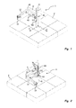
- Perspective view of an embodiment of a robotic device.
- Fig. 2:
- Perspective view of the robotic device of
Fig. 1 rotated through 90°. - Fig. 3:
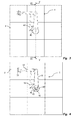
- Top view of the robotic device of
Fig. 1 . - Fig. 4:
- Horizontal section view of the device of
Fig. 1 . - Fig. 5:
- Vertical section view along line V-V of
Fig. 3 . - Fig. 6:
- Vertical section view along line VI-VI of
Fig. 3 . - In the following, an embodiment of the invention will be described in detail with reference to the drawings. Wherever possible, the same reference numbers are used throughout the drawings to refer to the same or like parts.
-
Fig. 1 to 6 show in schematic drawings an embodiment of arobotic device 1 used for example in a laboratory automation system for handling test tubes (not shown). - The
robotic device 1 comprises a stationary base 10 (shown inFigs. 5 and 6 ), afirst arm 11 rotationally mounted on thebase 10 for rotation about a first axis I, and asecond arm 12 rotationally mounted on thefirst arm 11 for rotation about a second axis II, which second axis II is parallel to the first axis I. At a distal end of thesecond arm 12, a work unit, namely agripper 13 is provided. If required by the application, thegripper 13 can be mounted rotatably on thesecond arm 12. - In the embodiment shown, the
base 10 is arranged stationary underneath a working table 2. In other embodiments, thebase 10 is provided above the working table 2 or therobotic device 1 is used without any working table. The base 10 in one embodiment comprises a housing. In other embodiments, thebase 10 is integrated in the environment. - The
first arm 11 is mounted to thebase 10 by afirst column 14, whichfirst column 14 is driven to rotate about the first axis I by afirst driving device 30. In the embodiment shown, thefirst driving device 30 is an electric motor. Between thefirst driving device 30 and the first column 14 a gearing system is provided, which is not shown in the figures. - The
first arm 11 is non-rotatably, but axially displaceably along the first axis I coupled to thefirst column 14. - As can be best seen in the horizontal section view of
Fig. 4 , thefirst column 14 is a hollow profile provided with a guidinggroove 15 extending in the direction of the first axis I. Thefirst arm 11 comprises aslider element 15 slidingly mounted in the guidinggroove 15 of the first column. The guidinggroove 15 is undercut, i.e. its opening is smaller than its maximum width and theslider element 15 is retained in radial direction in the guidinggroove 14. A necking is formed at thefirst arm 11 adjacent to theslider element 15. The flanks of the necking abut flanks of thefirst column 14 to positively connect thefirst arm 11 to thefirst column 14 for rotation with thefirst column 14. - A second
arm drive unit 4 with asecond driving device 40 is provided for driving thesecond arm 12 to rotate with respect to thefirst arm 11 about the second axis II. In the embodiment shown, the secondarm drive unit 4 comprises asecond column 41. Thesecond column 41 is a hollow profile. Thefirst column 14 and thesecond column 41 are arranged coaxially, wherein thefirst column 14 is arranged inside thesecond column 14, such that thesecond column 41 is rotatable about thefirst column 14. Thesecond column 41 is provided with a cutout for thefirst arm 11, which is designed to allow a rotation of thesecond column 41 with respect to thefirst column 14 without an interference of thesecond column 41 and thefirst arm 11. - The
second column 41 is driven to rotate about the first axis I by thesecond driving device 40. In the embodiment shown, thesecond driving device 40 is an electric motor. Between thesecond driving device 40 and the second column 41 a gearing system is provided, which is not shown in the figures. The rotation of thesecond column 41 is transferred to thesecond arm 12 by a linkage system. In the figures, thesecond arm 12 is linked to thesecond column 41 by means of a linkage system comprising tworods 42 arranged in parallel in a common plane parallel to the fist axis I. Therods 42 are rotatably about a rod axis III parallel to the first axis I and axially displaceably mounted on thesecond column 41. For this purpose, the linkage system shown further comprises acantilever 43. Thecantilever 43 is non-rotatably, but axially displaceably coupled to thesecond column 41 by guidingrail 44 extending in parallel to the first axis I at the outer surface of thesecond column 41. The tworods 42 are rotatably about the rod axis III and axially fixed coupled tocantilever 43. - A
control device 6 is provided, wherein by means of thecontrol device 6 thefirst driving device 30 and thesecond driving device 40 are either conjointly or separately driven to position thegripper 13 in the plane perpendicular to the first axis I and the second axis II, In other words, when choosing a Cartesian coordinate system having its origin at the intersection of the working table 2 and the first axis I and a vertical Z-axis thegripper 13 is positioned in the X-axis and the Y-axis. - The
robotic device 1 further comprises a linear drive unit 5 for moving thefirst arm 11 and thesecond arm 12 in a direction parallel to the first axis I and the second axis II, i.e. along the Z-axis of the Cartesian space. - The linear drive unit 5 comprises a
third driving device 50 driving a threaded rod 51 arranged at a fixed position to rotate about an axis. In the embodiment shown, the threaded rod 51 is arranged inside thefirst column 14 and coaxially to the first axis I. Hence, the threaded rod 51 is driven to rotate about the first axis I. - The
first arm 11, more particular theslider element 16 of thefirst arm 11 is provided with two nuts 52 engaging the threaded rod 51. - The
control device 6 controls thefirst driving device 30 and thethird driving device 50 to drive the threaded rod 51 and/or the first column to rotate about the first axis I. - When driving the threaded rod 51 to rotate about the first axis I and blocking a rotation of the
first column 14 and, hence, theslider element 16 non-rotatably coupled to thefirst column 14, theslider element 16 and, thus, thefirst arm 11 travels along the threadedrod 41. Thesecond arm 12 mounted to thefirst arm 11 is dragged to move with thefirst arm 14, wherein thecantilever 43 travels along the guidingrail 44. - The maximum travel length of the
first arm 11 along the threadedrod 41 is defined by the length of the guidinggroove 15. In the figures, the guidinggroove 15 does not reach over the entire length of thefirst column 14. Hence, a solid limit stop is provided, which limits a movement of thegripper 13 towards the working table 2 and prevents thegripper 13 from coming into collision with the working table 2. - When driving the threaded rod 51 and the
first column 14 to rotate about the first axis I with coordinated angular velocities, the threaded rod 51 and thefirst arm 11 rotate conjointly about the first axis I for rotationally positioning thefirst arm 11 without lifting or lowering thefirst arm 11. - All three driving
devices base 10. Hence, thearms devices arms gripper 13 to rotate with respect to thesecond arm 12. - The threaded rod 51, the
first column 14 and thesecond column 41 are arranged coaxially and are at least essentially aligned in the axial direction. For this purpose, thefirst column 14 and thesecond column 41 are designed as hollow profiles, wherein the threaded rod 51 is rotatably received by thefirst column 14, which is rotatably received by thesecond column 41. Thefirst column 14 and thesecond column 41 both have a circular cross section for allowing a rotation with respect to one another with a minimum space requirement. - The
robotic device 1 in one embodiment is used in a laboratory automation system for handling test tubes (not shown). The lightweight design of therobotic device 1 allows a handling of the test tubes at high velocities and high accelerations and with high precision and inducing only minor vibrations. - Of course, the use of the
robotic device 1 neither limited to pick-and-place operations nor to a use in a laboratory automation system. Other working units than thegripper 13 can be attached to the distal end of thesecond arm 12 for adapting therobotic device 1 to different operations.
Claims (15)
- Robotic device comprising a stationary base (10), a first arm (11) rotationally mounted on the base (10) for rotation about a first axis (I), a second arm (12) rotationally mounted on the first arm (11) for rotation about a second axis (II), which second axis (II) is parallel to the first axis (I), a first driving device (30) for driving the first arm (11) to rotate about the first axis (I), and a second arm drive unit (4) with a second driving device (40) for driving the second arm (12) to rotate about the second axis (I), wherein the first driving device (30) and the second driving devices (40) are mounted stationary at the base (1),
characterized in that
a linear drive unit (4) is provided for moving the first arm (11) and the second arm (12) in a direction parallel to the first axis (I) and the second axis (II), wherein the linear drive unit (4) comprises a third driving device (40) mounted stationary at the base (10). - Robotic device according to claim 1, characterized in that the linear drive unit (4) comprises a threaded rod (41) rotating about a fixed third axis and at least one nut (42) engaging the threaded rod (41), which at least one nut is mounted on the first arm (11).
- Robotic device according to claim 2, characterized in that the third axis is coaxial with the first axis (I).
- Robotic device according to claim 1, 2 or 3, characterized in that the first arm (11) is mounted to the base (10) by a first column (14) driven to rotate about the first axis (I), wherein the first arm (11) is non-rotatably, but axially displaceably along the first axis (I) coupled to the first column (14).
- Robotic device according to claim 4, characterized in that the first arm (11) comprises a slider element (16) slidingly mounted in a guiding groove (15) of the first column (14) extending in the direction of the first axis (I) and positively connected to the first column (14) to rotate with the first column (14).
- Robotic device according to claim 4 or 5, characterized in that the first column (14) is a hollow profile.
- Robotic device according to claim 4, 5 or 6, characterized in that the second arm drive unit (4) comprises a second column (41) driven to rotate about the first axis (I).
- Robotic device according to claim 7, characterized in that the second column (41) is a hollow profile, wherein the first column (14) is arranged inside the second column (41), such that the second column (41) is rotatable about the first column (14).
- Robotic device according to claim 8, characterized in that the second arm (12) is linked to the second column (41) by means of a linkage system comprising at least one rod (42), which is rotatably about a rod axis (III) parallel to the first axis (I) and axially displaceably mounted on the second column (41).
- Robotic device according to claim 9, characterized in that the linkage system comprises at least one cantilever (43), which is non-rotatably, but axially displaceably in the axial direction of the second column (41) coupled to the second column (41), wherein the at least one rod (42) is rotatably about the rod axis (III) and axially fixed coupled to the cantilever (43).
- Robotic device according to claim 10, characterized in that at least one guiding rail (44) extending in parallel to the first axis (I) is provided at the outer surface of the second column (41), wherein the at least one cantilever (43) is slidingly coupled to the at least one guiding rail (44).
- Robotic device according to any one of claims 1 to 11, characterized in that at least one control device (6) is provided, wherein the first driving device (30), the second driving device (40), and the third driving device (50) are coordinated by means of the control device (6) to position the robotic device (1) in Cartesian space.
- Robotic device according to any one of claims 1 to 12, characterized in that a work unit, in particular a gripper (13), is attached to the second arm (12).
- Robotic device according to claim 13, characterized in that the work unit is mounted moveable on the second arm (12), in particular swivelable with respect to the second arm (12).
- Laboratory automation system with a number of pre-analytical, analytical and/or post-analytical stations, and with a robotic device (1) according to any one of claims 1 to 14.
Priority Applications (4)
| Application Number | Priority Date | Filing Date | Title |
|---|---|---|---|
| EP15154519.1A EP3056320B1 (en) | 2015-02-10 | 2015-02-10 | Robotic device and laboratory automation system comprising robotic device |
| JP2016012420A JP6681203B2 (en) | 2015-02-10 | 2016-01-26 | Robot device and laboratory automation system including robot device |
| CN201610081537.4A CN105856247B (en) | 2015-02-10 | 2016-02-05 | Robotic device and laboratory automation system comprising a robotic device |
| US15/040,383 US9751208B2 (en) | 2015-02-10 | 2016-02-10 | Robotic device and laboratory automation system comprising robotic device |
Applications Claiming Priority (1)
| Application Number | Priority Date | Filing Date | Title |
|---|---|---|---|
| EP15154519.1A EP3056320B1 (en) | 2015-02-10 | 2015-02-10 | Robotic device and laboratory automation system comprising robotic device |
Publications (2)
| Publication Number | Publication Date |
|---|---|
| EP3056320A1 true EP3056320A1 (en) | 2016-08-17 |
| EP3056320B1 EP3056320B1 (en) | 2018-12-05 |
Family
ID=52462248
Family Applications (1)
| Application Number | Title | Priority Date | Filing Date |
|---|---|---|---|
| EP15154519.1A Active EP3056320B1 (en) | 2015-02-10 | 2015-02-10 | Robotic device and laboratory automation system comprising robotic device |
Country Status (4)
| Country | Link |
|---|---|
| US (1) | US9751208B2 (en) |
| EP (1) | EP3056320B1 (en) |
| JP (1) | JP6681203B2 (en) |
| CN (1) | CN105856247B (en) |
Cited By (6)
| Publication number | Priority date | Publication date | Assignee | Title |
|---|---|---|---|---|
| CN106625673A (en) * | 2016-12-29 | 2017-05-10 | 南京天祥智能设备科技有限公司 | Narrow space assembly system and assembly method |
| CN110282408A (en) * | 2018-08-30 | 2019-09-27 | 南京禹智智能科技有限公司 | An anti-shaking unloading robot for industrial production |
| WO2022101460A1 (en) | 2020-11-16 | 2022-05-19 | Roche Diagnostics Gmbh | Monitoring device for monitoring an electric motor in a laboratory system |
| CN114658728A (en) * | 2020-12-22 | 2022-06-24 | 豪夫迈·罗氏有限公司 | Connection joint for connecting components of a laboratory automation system |
| WO2022243511A1 (en) | 2021-05-21 | 2022-11-24 | F. Hoffmann-La Roche Ag | Automatic registration of at least one device in a laboratory system |
| US12620481B2 (en) | 2021-05-21 | 2026-05-05 | Roche Diagnostics Operations, Inc. | Automatic registration of at least one device in a laboratory system |
Families Citing this family (11)
| Publication number | Priority date | Publication date | Assignee | Title |
|---|---|---|---|---|
| JP6946288B2 (en) * | 2016-06-15 | 2021-10-06 | 株式会社三共製作所 | Transport device |
| CN206537925U (en) * | 2016-10-20 | 2017-10-03 | 京东方科技集团股份有限公司 | A kind of feeding device for line source crucible |
| CN106881710A (en) * | 2017-04-19 | 2017-06-23 | 中北大学 | It is a kind of to become the pickup robot for driving five bar parallel institutions of layout |
| CN108045929A (en) * | 2017-11-27 | 2018-05-18 | 马鞍山云林百成机械制造有限公司 | A kind of liner blank transports positioner |
| CN107879096B (en) * | 2017-12-01 | 2023-12-19 | 北京电子科技职业学院 | Electrode spreading clamp and feeding device |
| CN107972049B (en) * | 2018-01-18 | 2023-07-28 | 开封市平安电器有限公司 | Manipulator for massaging and hammering |
| CN108544505B (en) * | 2018-04-19 | 2020-07-17 | 广州天地林业有限公司 | Agriculture and forestry ecology monitoring and maintenance robot |
| JP7169370B2 (en) * | 2018-12-28 | 2022-11-10 | 川崎重工業株式会社 | ROBOT CONTROL DEVICE, ROBOT SYSTEM AND ROBOT CONTROL METHOD |
| CN110405735A (en) * | 2019-08-05 | 2019-11-05 | 姚聪 | A kind of intelligent robot grabbing device |
| IT202000002314A1 (en) * | 2020-02-06 | 2021-08-06 | Gd Spa | Feeding unit for a packaging machine and its feeding method |
| CN116424849A (en) * | 2023-02-11 | 2023-07-14 | 江西络鑫科技有限公司 | A loading and unloading device for electronic product production |
Citations (7)
| Publication number | Priority date | Publication date | Assignee | Title |
|---|---|---|---|---|
| US4947702A (en) * | 1988-06-14 | 1990-08-14 | Mitsubishi Denki Kabushiki Kaisha | Industrial robot |
| US5741113A (en) | 1995-07-10 | 1998-04-21 | Kensington Laboratories, Inc. | Continuously rotatable multiple link robot arm mechanism |
| DE202005017588U1 (en) * | 2005-11-10 | 2006-02-02 | Robert Bosch Gmbh | Robot for implementation of handling operations in a clean room, of e.g. pharmaceutical plant, comprises sealing elements which completely seal the interior of the robot arm from the atmosphere of the clean room |
| US20080041183A1 (en) * | 2006-06-28 | 2008-02-21 | Genmark Automation, Inc. | Belt-driven robot having extended Z-axis motion |
| US7347120B2 (en) | 2003-10-23 | 2008-03-25 | Staubli Faverges | Robot of SCARA type |
| EP2148206A1 (en) | 2008-07-25 | 2010-01-27 | F.Hoffmann-La Roche Ag | A laboratory system for handling sample tube racks, an alignmemt element for sample tube racks and a rack tray receiver assembly |
| US20110135426A1 (en) * | 2008-01-31 | 2011-06-09 | Canon Anelva Corporation | Vacuum transfer apparatus |
Family Cites Families (14)
| Publication number | Priority date | Publication date | Assignee | Title |
|---|---|---|---|---|
| US3031906A (en) * | 1956-10-30 | 1962-05-01 | Voit Rubber Corp | Stacking machine |
| FR2527967B1 (en) * | 1982-06-07 | 1985-07-19 | Merlin Gerin | PERFECTED INDUSTRIAL ROBOT DRIVED BY A PROGRAMMABLE PLC |
| NL8502525A (en) * | 1985-09-16 | 1987-04-16 | Groot R Holding Laag Zuthem Bv | MANIPULATOR. |
| JPS62251090A (en) * | 1986-04-21 | 1987-10-31 | 株式会社東芝 | Industrial robot |
| JPH0319781A (en) * | 1989-06-14 | 1991-01-28 | Mitsubishi Electric Corp | Industrial robot device |
| AU5466200A (en) * | 1999-06-04 | 2000-12-28 | Distributed Robotics, Llc | Material handling device |
| US7891935B2 (en) * | 2002-05-09 | 2011-02-22 | Brooks Automation, Inc. | Dual arm robot |
| JP5078738B2 (en) * | 2008-05-07 | 2012-11-21 | 新電元工業株式会社 | Robot for workpiece transfer |
| US8528438B2 (en) * | 2009-11-25 | 2013-09-10 | Chung-Shan Institute Of Science And Technology, Armaments Bureau, Ministry Of National Defense | Robotic arm for transporting substrate in ultrahigh vacuum |
| GB2481249A (en) * | 2010-06-20 | 2011-12-21 | Innovations Ltd M | Three dimensional selective compliant robot |
| WO2012125572A2 (en) * | 2011-03-11 | 2012-09-20 | Brooks Automation, Inc. | Substrate processing tool |
| CN103493193A (en) * | 2011-04-15 | 2014-01-01 | 龙云株式会社 | Wafer exchange device and hand for wafer support |
| US9076829B2 (en) * | 2011-08-08 | 2015-07-07 | Applied Materials, Inc. | Robot systems, apparatus, and methods adapted to transport substrates in electronic device manufacturing |
| TWI546170B (en) * | 2012-12-24 | 2016-08-21 | 台達電子工業股份有限公司 | Methods and apparatus for driving a robot |
-
2015
- 2015-02-10 EP EP15154519.1A patent/EP3056320B1/en active Active
-
2016
- 2016-01-26 JP JP2016012420A patent/JP6681203B2/en active Active
- 2016-02-05 CN CN201610081537.4A patent/CN105856247B/en active Active
- 2016-02-10 US US15/040,383 patent/US9751208B2/en active Active
Patent Citations (7)
| Publication number | Priority date | Publication date | Assignee | Title |
|---|---|---|---|---|
| US4947702A (en) * | 1988-06-14 | 1990-08-14 | Mitsubishi Denki Kabushiki Kaisha | Industrial robot |
| US5741113A (en) | 1995-07-10 | 1998-04-21 | Kensington Laboratories, Inc. | Continuously rotatable multiple link robot arm mechanism |
| US7347120B2 (en) | 2003-10-23 | 2008-03-25 | Staubli Faverges | Robot of SCARA type |
| DE202005017588U1 (en) * | 2005-11-10 | 2006-02-02 | Robert Bosch Gmbh | Robot for implementation of handling operations in a clean room, of e.g. pharmaceutical plant, comprises sealing elements which completely seal the interior of the robot arm from the atmosphere of the clean room |
| US20080041183A1 (en) * | 2006-06-28 | 2008-02-21 | Genmark Automation, Inc. | Belt-driven robot having extended Z-axis motion |
| US20110135426A1 (en) * | 2008-01-31 | 2011-06-09 | Canon Anelva Corporation | Vacuum transfer apparatus |
| EP2148206A1 (en) | 2008-07-25 | 2010-01-27 | F.Hoffmann-La Roche Ag | A laboratory system for handling sample tube racks, an alignmemt element for sample tube racks and a rack tray receiver assembly |
Cited By (8)
| Publication number | Priority date | Publication date | Assignee | Title |
|---|---|---|---|---|
| CN106625673A (en) * | 2016-12-29 | 2017-05-10 | 南京天祥智能设备科技有限公司 | Narrow space assembly system and assembly method |
| CN106625673B (en) * | 2016-12-29 | 2019-09-24 | 南京天祥智能设备科技有限公司 | Small space assembly system and assembly method |
| CN110282408A (en) * | 2018-08-30 | 2019-09-27 | 南京禹智智能科技有限公司 | An anti-shaking unloading robot for industrial production |
| CN110282408B (en) * | 2018-08-30 | 2020-07-10 | 南京禹智智能科技有限公司 | Prevent rocking industrial production with robot of unloading |
| WO2022101460A1 (en) | 2020-11-16 | 2022-05-19 | Roche Diagnostics Gmbh | Monitoring device for monitoring an electric motor in a laboratory system |
| CN114658728A (en) * | 2020-12-22 | 2022-06-24 | 豪夫迈·罗氏有限公司 | Connection joint for connecting components of a laboratory automation system |
| WO2022243511A1 (en) | 2021-05-21 | 2022-11-24 | F. Hoffmann-La Roche Ag | Automatic registration of at least one device in a laboratory system |
| US12620481B2 (en) | 2021-05-21 | 2026-05-05 | Roche Diagnostics Operations, Inc. | Automatic registration of at least one device in a laboratory system |
Also Published As
| Publication number | Publication date |
|---|---|
| JP6681203B2 (en) | 2020-04-15 |
| JP2016147368A (en) | 2016-08-18 |
| CN105856247B (en) | 2020-09-04 |
| US9751208B2 (en) | 2017-09-05 |
| EP3056320B1 (en) | 2018-12-05 |
| CN105856247A (en) | 2016-08-17 |
| US20160229051A1 (en) | 2016-08-11 |
Similar Documents
| Publication | Publication Date | Title |
|---|---|---|
| EP3056320B1 (en) | Robotic device and laboratory automation system comprising robotic device | |
| EP3195988B1 (en) | Five-degree-of-freedom parallel robot with multi-shaft rotary brackets | |
| US10773393B2 (en) | Auxiliary bending robot capable of processing two workpieces simultaneously | |
| KR850000548B1 (en) | Industrial robot | |
| EP2554337B1 (en) | Robot including telescopic lead screw assemblies for positioning an end effector | |
| CA2286538C (en) | Robot arm | |
| US4534006A (en) | Operating arm unit controlled by a computer system | |
| US3916701A (en) | Rotary wrist actuator for industrial robots | |
| EP1911551A1 (en) | Cross-guiding motion platform | |
| EP3588099B1 (en) | Positioning assembly for a laboratory apparatus | |
| US4352620A (en) | Industrial robot | |
| US20120003073A1 (en) | Tooling device | |
| CA2935520A1 (en) | Robot for industrial use | |
| US11185995B2 (en) | Robot gripper having a drive device | |
| CN204800633U (en) | Electric combination driven rectangular coordinate is manipulator | |
| CN105904216A (en) | High-precision multi-axis numerical control machine tool | |
| CN116547114A (en) | Working device | |
| CN113829332A (en) | A four-degree parallel robot mechanism with three movements and one rotation | |
| EP2463183B1 (en) | Workpiece positioning device and production system using it | |
| CN106903495A (en) | A kind of robot mechanism that assembly manipulation is directed at for heavy parts | |
| CN105364922B (en) | Four-freedom-degree parallel type transfer robot driven by movable pairs | |
| CN105522572B (en) | The shaft industrial robot of compact three | |
| CN213481129U (en) | Novel target simulation fitting motion platform | |
| CN119188701B (en) | A telescopic robot capable of detecting the inner cavity of large structural parts | |
| CN223222724U (en) | Positioning device |
Legal Events
| Date | Code | Title | Description |
|---|---|---|---|
| PUAI | Public reference made under article 153(3) epc to a published international application that has entered the european phase |
Free format text: ORIGINAL CODE: 0009012 |
|
| AK | Designated contracting states |
Kind code of ref document: A1 Designated state(s): AL AT BE BG CH CY CZ DE DK EE ES FI FR GB GR HR HU IE IS IT LI LT LU LV MC MK MT NL NO PL PT RO RS SE SI SK SM TR |
|
| AX | Request for extension of the european patent |
Extension state: BA ME |
|
| STAA | Information on the status of an ep patent application or granted ep patent |
Free format text: STATUS: REQUEST FOR EXAMINATION WAS MADE |
|
| 17P | Request for examination filed |
Effective date: 20170112 |
|
| RBV | Designated contracting states (corrected) |
Designated state(s): AL AT BE BG CH CY CZ DE DK EE ES FI FR GB GR HR HU IE IS IT LI LT LU LV MC MK MT NL NO PL PT RO RS SE SI SK SM TR |
|
| GRAP | Despatch of communication of intention to grant a patent |
Free format text: ORIGINAL CODE: EPIDOSNIGR1 |
|
| STAA | Information on the status of an ep patent application or granted ep patent |
Free format text: STATUS: GRANT OF PATENT IS INTENDED |
|
| INTG | Intention to grant announced |
Effective date: 20180704 |
|
| GRAS | Grant fee paid |
Free format text: ORIGINAL CODE: EPIDOSNIGR3 |
|
| GRAA | (expected) grant |
Free format text: ORIGINAL CODE: 0009210 |
|
| GRAA | (expected) grant |
Free format text: ORIGINAL CODE: 0009210 |
|
| STAA | Information on the status of an ep patent application or granted ep patent |
Free format text: STATUS: THE PATENT HAS BEEN GRANTED |
|
| AK | Designated contracting states |
Kind code of ref document: B1 Designated state(s): AL AT BE BG CH CY CZ DE DK EE ES FI FR GB GR HR HU IE IS IT LI LT LU LV MC MK MT NL NO PL PT RO RS SE SI SK SM TR |
|
| REG | Reference to a national code |
Ref country code: GB Ref legal event code: FG4D |
|
| RIN1 | Information on inventor provided before grant (corrected) |
Inventor name: EDELMANN, MATTHIAS |
|
| REG | Reference to a national code |
Ref country code: CH Ref legal event code: EP |
|
| REG | Reference to a national code |
Ref country code: AT Ref legal event code: REF Ref document number: 1072455 Country of ref document: AT Kind code of ref document: T Effective date: 20181215 |
|
| REG | Reference to a national code |
Ref country code: IE Ref legal event code: FG4D |
|
| REG | Reference to a national code |
Ref country code: DE Ref legal event code: R096 Ref document number: 602015020692 Country of ref document: DE |
|
| REG | Reference to a national code |
Ref country code: NL Ref legal event code: MP Effective date: 20181205 |
|
| REG | Reference to a national code |
Ref country code: AT Ref legal event code: MK05 Ref document number: 1072455 Country of ref document: AT Kind code of ref document: T Effective date: 20181205 |
|
| REG | Reference to a national code |
Ref country code: LT Ref legal event code: MG4D |
|
| PG25 | Lapsed in a contracting state [announced via postgrant information from national office to epo] |
Ref country code: FI Free format text: LAPSE BECAUSE OF FAILURE TO SUBMIT A TRANSLATION OF THE DESCRIPTION OR TO PAY THE FEE WITHIN THE PRESCRIBED TIME-LIMIT Effective date: 20181205 Ref country code: BG Free format text: LAPSE BECAUSE OF FAILURE TO SUBMIT A TRANSLATION OF THE DESCRIPTION OR TO PAY THE FEE WITHIN THE PRESCRIBED TIME-LIMIT Effective date: 20190305 Ref country code: LT Free format text: LAPSE BECAUSE OF FAILURE TO SUBMIT A TRANSLATION OF THE DESCRIPTION OR TO PAY THE FEE WITHIN THE PRESCRIBED TIME-LIMIT Effective date: 20181205 Ref country code: AT Free format text: LAPSE BECAUSE OF FAILURE TO SUBMIT A TRANSLATION OF THE DESCRIPTION OR TO PAY THE FEE WITHIN THE PRESCRIBED TIME-LIMIT Effective date: 20181205 Ref country code: NO Free format text: LAPSE BECAUSE OF FAILURE TO SUBMIT A TRANSLATION OF THE DESCRIPTION OR TO PAY THE FEE WITHIN THE PRESCRIBED TIME-LIMIT Effective date: 20190305 Ref country code: ES Free format text: LAPSE BECAUSE OF FAILURE TO SUBMIT A TRANSLATION OF THE DESCRIPTION OR TO PAY THE FEE WITHIN THE PRESCRIBED TIME-LIMIT Effective date: 20181205 Ref country code: HR Free format text: LAPSE BECAUSE OF FAILURE TO SUBMIT A TRANSLATION OF THE DESCRIPTION OR TO PAY THE FEE WITHIN THE PRESCRIBED TIME-LIMIT Effective date: 20181205 Ref country code: LV Free format text: LAPSE BECAUSE OF FAILURE TO SUBMIT A TRANSLATION OF THE DESCRIPTION OR TO PAY THE FEE WITHIN THE PRESCRIBED TIME-LIMIT Effective date: 20181205 |
|
| PG25 | Lapsed in a contracting state [announced via postgrant information from national office to epo] |
Ref country code: AL Free format text: LAPSE BECAUSE OF FAILURE TO SUBMIT A TRANSLATION OF THE DESCRIPTION OR TO PAY THE FEE WITHIN THE PRESCRIBED TIME-LIMIT Effective date: 20181205 Ref country code: SE Free format text: LAPSE BECAUSE OF FAILURE TO SUBMIT A TRANSLATION OF THE DESCRIPTION OR TO PAY THE FEE WITHIN THE PRESCRIBED TIME-LIMIT Effective date: 20181205 Ref country code: RS Free format text: LAPSE BECAUSE OF FAILURE TO SUBMIT A TRANSLATION OF THE DESCRIPTION OR TO PAY THE FEE WITHIN THE PRESCRIBED TIME-LIMIT Effective date: 20181205 Ref country code: GR Free format text: LAPSE BECAUSE OF FAILURE TO SUBMIT A TRANSLATION OF THE DESCRIPTION OR TO PAY THE FEE WITHIN THE PRESCRIBED TIME-LIMIT Effective date: 20190306 |
|
| PG25 | Lapsed in a contracting state [announced via postgrant information from national office to epo] |
Ref country code: NL Free format text: LAPSE BECAUSE OF FAILURE TO SUBMIT A TRANSLATION OF THE DESCRIPTION OR TO PAY THE FEE WITHIN THE PRESCRIBED TIME-LIMIT Effective date: 20181205 |
|
| PG25 | Lapsed in a contracting state [announced via postgrant information from national office to epo] |
Ref country code: PL Free format text: LAPSE BECAUSE OF FAILURE TO SUBMIT A TRANSLATION OF THE DESCRIPTION OR TO PAY THE FEE WITHIN THE PRESCRIBED TIME-LIMIT Effective date: 20181205 Ref country code: CZ Free format text: LAPSE BECAUSE OF FAILURE TO SUBMIT A TRANSLATION OF THE DESCRIPTION OR TO PAY THE FEE WITHIN THE PRESCRIBED TIME-LIMIT Effective date: 20181205 Ref country code: PT Free format text: LAPSE BECAUSE OF FAILURE TO SUBMIT A TRANSLATION OF THE DESCRIPTION OR TO PAY THE FEE WITHIN THE PRESCRIBED TIME-LIMIT Effective date: 20190405 |
|
| PG25 | Lapsed in a contracting state [announced via postgrant information from national office to epo] |
Ref country code: SM Free format text: LAPSE BECAUSE OF FAILURE TO SUBMIT A TRANSLATION OF THE DESCRIPTION OR TO PAY THE FEE WITHIN THE PRESCRIBED TIME-LIMIT Effective date: 20181205 Ref country code: EE Free format text: LAPSE BECAUSE OF FAILURE TO SUBMIT A TRANSLATION OF THE DESCRIPTION OR TO PAY THE FEE WITHIN THE PRESCRIBED TIME-LIMIT Effective date: 20181205 Ref country code: IS Free format text: LAPSE BECAUSE OF FAILURE TO SUBMIT A TRANSLATION OF THE DESCRIPTION OR TO PAY THE FEE WITHIN THE PRESCRIBED TIME-LIMIT Effective date: 20190405 Ref country code: RO Free format text: LAPSE BECAUSE OF FAILURE TO SUBMIT A TRANSLATION OF THE DESCRIPTION OR TO PAY THE FEE WITHIN THE PRESCRIBED TIME-LIMIT Effective date: 20181205 Ref country code: SK Free format text: LAPSE BECAUSE OF FAILURE TO SUBMIT A TRANSLATION OF THE DESCRIPTION OR TO PAY THE FEE WITHIN THE PRESCRIBED TIME-LIMIT Effective date: 20181205 |
|
| REG | Reference to a national code |
Ref country code: DE Ref legal event code: R097 Ref document number: 602015020692 Country of ref document: DE |
|
| PLBE | No opposition filed within time limit |
Free format text: ORIGINAL CODE: 0009261 |
|
| STAA | Information on the status of an ep patent application or granted ep patent |
Free format text: STATUS: NO OPPOSITION FILED WITHIN TIME LIMIT |
|
| PG25 | Lapsed in a contracting state [announced via postgrant information from national office to epo] |
Ref country code: DK Free format text: LAPSE BECAUSE OF FAILURE TO SUBMIT A TRANSLATION OF THE DESCRIPTION OR TO PAY THE FEE WITHIN THE PRESCRIBED TIME-LIMIT Effective date: 20181205 Ref country code: SI Free format text: LAPSE BECAUSE OF FAILURE TO SUBMIT A TRANSLATION OF THE DESCRIPTION OR TO PAY THE FEE WITHIN THE PRESCRIBED TIME-LIMIT Effective date: 20181205 Ref country code: LU Free format text: LAPSE BECAUSE OF NON-PAYMENT OF DUE FEES Effective date: 20190210 Ref country code: MC Free format text: LAPSE BECAUSE OF FAILURE TO SUBMIT A TRANSLATION OF THE DESCRIPTION OR TO PAY THE FEE WITHIN THE PRESCRIBED TIME-LIMIT Effective date: 20181205 |
|
| 26N | No opposition filed |
Effective date: 20190906 |
|
| REG | Reference to a national code |
Ref country code: BE Ref legal event code: MM Effective date: 20190228 |
|
| REG | Reference to a national code |
Ref country code: IE Ref legal event code: MM4A |
|
| PG25 | Lapsed in a contracting state [announced via postgrant information from national office to epo] |
Ref country code: IE Free format text: LAPSE BECAUSE OF NON-PAYMENT OF DUE FEES Effective date: 20190210 |
|
| PG25 | Lapsed in a contracting state [announced via postgrant information from national office to epo] |
Ref country code: BE Free format text: LAPSE BECAUSE OF NON-PAYMENT OF DUE FEES Effective date: 20190228 |
|
| PG25 | Lapsed in a contracting state [announced via postgrant information from national office to epo] |
Ref country code: TR Free format text: LAPSE BECAUSE OF FAILURE TO SUBMIT A TRANSLATION OF THE DESCRIPTION OR TO PAY THE FEE WITHIN THE PRESCRIBED TIME-LIMIT Effective date: 20181205 |
|
| PG25 | Lapsed in a contracting state [announced via postgrant information from national office to epo] |
Ref country code: MT Free format text: LAPSE BECAUSE OF NON-PAYMENT OF DUE FEES Effective date: 20190210 |
|
| PG25 | Lapsed in a contracting state [announced via postgrant information from national office to epo] |
Ref country code: CY Free format text: LAPSE BECAUSE OF FAILURE TO SUBMIT A TRANSLATION OF THE DESCRIPTION OR TO PAY THE FEE WITHIN THE PRESCRIBED TIME-LIMIT Effective date: 20181205 |
|
| PG25 | Lapsed in a contracting state [announced via postgrant information from national office to epo] |
Ref country code: HU Free format text: LAPSE BECAUSE OF FAILURE TO SUBMIT A TRANSLATION OF THE DESCRIPTION OR TO PAY THE FEE WITHIN THE PRESCRIBED TIME-LIMIT; INVALID AB INITIO Effective date: 20150210 |
|
| PG25 | Lapsed in a contracting state [announced via postgrant information from national office to epo] |
Ref country code: MK Free format text: LAPSE BECAUSE OF FAILURE TO SUBMIT A TRANSLATION OF THE DESCRIPTION OR TO PAY THE FEE WITHIN THE PRESCRIBED TIME-LIMIT Effective date: 20181205 |
|
| REG | Reference to a national code |
Ref country code: CH Ref legal event code: U11 Free format text: ST27 STATUS EVENT CODE: U-0-0-U10-U11 (AS PROVIDED BY THE NATIONAL OFFICE) Effective date: 20260301 |
|
| PGFP | Annual fee paid to national office [announced via postgrant information from national office to epo] |
Ref country code: GB Payment date: 20260122 Year of fee payment: 12 |
|
| PGFP | Annual fee paid to national office [announced via postgrant information from national office to epo] |
Ref country code: DE Payment date: 20260121 Year of fee payment: 12 |
|
| PGFP | Annual fee paid to national office [announced via postgrant information from national office to epo] |
Ref country code: IT Payment date: 20260121 Year of fee payment: 12 |
|
| PGFP | Annual fee paid to national office [announced via postgrant information from national office to epo] |
Ref country code: FR Payment date: 20260121 Year of fee payment: 12 |
|
| PGFP | Annual fee paid to national office [announced via postgrant information from national office to epo] |
Ref country code: CH Payment date: 20260301 Year of fee payment: 12 |