EP3056133A1 - Endoscopic system - Google Patents
Endoscopic system Download PDFInfo
- Publication number
- EP3056133A1 EP3056133A1 EP14853067.8A EP14853067A EP3056133A1 EP 3056133 A1 EP3056133 A1 EP 3056133A1 EP 14853067 A EP14853067 A EP 14853067A EP 3056133 A1 EP3056133 A1 EP 3056133A1
- Authority
- EP
- European Patent Office
- Prior art keywords
- observation window
- determination
- observation
- luminance level
- pixels
- Prior art date
- Legal status (The legal status is an assumption and is not a legal conclusion. Google has not performed a legal analysis and makes no representation as to the accuracy of the status listed.)
- Granted
Links
Images



Classifications
-
- A—HUMAN NECESSITIES
- A61—MEDICAL OR VETERINARY SCIENCE; HYGIENE
- A61B—DIAGNOSIS; SURGERY; IDENTIFICATION
- A61B1/00—Instruments for performing medical examinations of the interior of cavities or tubes of the body by visual or photographical inspection, e.g. endoscopes; Illuminating arrangements therefor
- A61B1/12—Instruments for performing medical examinations of the interior of cavities or tubes of the body by visual or photographical inspection, e.g. endoscopes; Illuminating arrangements therefor with cooling or rinsing arrangements
- A61B1/127—Instruments for performing medical examinations of the interior of cavities or tubes of the body by visual or photographical inspection, e.g. endoscopes; Illuminating arrangements therefor with cooling or rinsing arrangements with means for preventing fogging
-
- A—HUMAN NECESSITIES
- A61—MEDICAL OR VETERINARY SCIENCE; HYGIENE
- A61B—DIAGNOSIS; SURGERY; IDENTIFICATION
- A61B1/00—Instruments for performing medical examinations of the interior of cavities or tubes of the body by visual or photographical inspection, e.g. endoscopes; Illuminating arrangements therefor
- A61B1/00002—Operational features of endoscopes
- A61B1/00004—Operational features of endoscopes characterised by electronic signal processing
- A61B1/00009—Operational features of endoscopes characterised by electronic signal processing of image signals during a use of endoscope
- A61B1/000094—Operational features of endoscopes characterised by electronic signal processing of image signals during a use of endoscope extracting biological structures
-
- A—HUMAN NECESSITIES
- A61—MEDICAL OR VETERINARY SCIENCE; HYGIENE
- A61B—DIAGNOSIS; SURGERY; IDENTIFICATION
- A61B1/00—Instruments for performing medical examinations of the interior of cavities or tubes of the body by visual or photographical inspection, e.g. endoscopes; Illuminating arrangements therefor
- A61B1/00002—Operational features of endoscopes
- A61B1/00025—Operational features of endoscopes characterised by power management
- A61B1/00027—Operational features of endoscopes characterised by power management characterised by power supply
-
- A—HUMAN NECESSITIES
- A61—MEDICAL OR VETERINARY SCIENCE; HYGIENE
- A61B—DIAGNOSIS; SURGERY; IDENTIFICATION
- A61B1/00—Instruments for performing medical examinations of the interior of cavities or tubes of the body by visual or photographical inspection, e.g. endoscopes; Illuminating arrangements therefor
- A61B1/00002—Operational features of endoscopes
- A61B1/00057—Operational features of endoscopes provided with means for testing or calibration
-
- A—HUMAN NECESSITIES
- A61—MEDICAL OR VETERINARY SCIENCE; HYGIENE
- A61B—DIAGNOSIS; SURGERY; IDENTIFICATION
- A61B1/00—Instruments for performing medical examinations of the interior of cavities or tubes of the body by visual or photographical inspection, e.g. endoscopes; Illuminating arrangements therefor
- A61B1/12—Instruments for performing medical examinations of the interior of cavities or tubes of the body by visual or photographical inspection, e.g. endoscopes; Illuminating arrangements therefor with cooling or rinsing arrangements
- A61B1/128—Instruments for performing medical examinations of the interior of cavities or tubes of the body by visual or photographical inspection, e.g. endoscopes; Illuminating arrangements therefor with cooling or rinsing arrangements provided with means for regulating temperature
-
- G—PHYSICS
- G02—OPTICS
- G02B—OPTICAL ELEMENTS, SYSTEMS OR APPARATUS
- G02B23/00—Telescopes, e.g. binoculars; Periscopes; Instruments for viewing the inside of hollow bodies; Viewfinders; Optical aiming or sighting devices
- G02B23/24—Instruments or systems for viewing the inside of hollow bodies, e.g. fibrescopes
- G02B23/2476—Non-optical details, e.g. housings, mountings, supports
-
- G—PHYSICS
- G02—OPTICS
- G02B—OPTICAL ELEMENTS, SYSTEMS OR APPARATUS
- G02B27/00—Optical systems or apparatus not provided for by any of the groups G02B1/00 - G02B26/00, G02B30/00
- G02B27/0006—Optical systems or apparatus not provided for by any of the groups G02B1/00 - G02B26/00, G02B30/00 with means to keep optical surfaces clean, e.g. by preventing or removing dirt, stains, contamination, condensation
-
- H—ELECTRICITY
- H04—ELECTRIC COMMUNICATION TECHNIQUE
- H04N—PICTORIAL COMMUNICATION, e.g. TELEVISION
- H04N23/00—Cameras or camera modules comprising electronic image sensors; Control thereof
- H04N23/50—Constructional details
- H04N23/555—Constructional details for picking-up images in sites, inaccessible due to their dimensions or hazardous conditions, e.g. endoscopes or borescopes
Definitions
- the present invention relates to an endoscopic system having a fog prevention function of an observation window in an insertion portion of an endoscope.
- an observation window disposed at the distal end of an insertion portion of an endoscope is at a temperature equal to an outside ambient temperature of, for example, approximately 25°C before being inserted into a lumen that is an observation target.
- the environment inside the lumen is at a temperature of approximately 37°C and at a humidity of nearly 100%.
- a configuration known as a technique for removing the fog injects a cleaning fluid from an injection hole disposed in the vicinity of the observation window to remove the fog.
- the observation window again fogs up if its temperature is low.
- Jpn. Pat. Appln. KOKAI Publication No. 2006-282 suggests a configuration in which a heater serving as a heat source is disposed in the vicinity of an objective optical system serving as an observation window to prevent or remove the fog on the observation window.
- a temperature sensor for controlling the temperature of the heater is disposed in the distal end of an insertion portion in the vicinity of the heater, in addition to an electric power supply wire laid for supplying electricity to the heater, and a communication wire laid for acquiring temperature information.
- the temperature sensor is installed at the distal end of the insertion portion, so that the presence of the temperature sensor is a problem for a further reduction in the diameter of the insertion portion.
- an endoscopic system comprising: an endoscope in which an observation window is disposed at a distal end and which has an insertion portion to be inserted into a lumen; an imaging unit having an imaging surface comprising pixels to convert, into an image signal, an observation image which is focused through the observation window; a fog prevention heater disposed in the vicinity of the observation window; a luminance level detection section which detects the distribution of a luminance level resulting from the image signal output by the pixels of the imaging unit; a determination section which compares the distribution of the luminance level with a preset first determination standard and further compares the distribution of the luminance level with a threshold that is a preset second determination standard, and makes a determination so that the fog prevention heater performs a temperature raising operation on the basis of the comparisons; and a heater power supply which drives the fog prevention heater to raise the temperature of the observation window in accordance with the determination result in the determination section.
- FIG. 1 is a diagram showing an overall configuration example of an endoscopic system having a fog prevention configuration in the distal end of an insertion portion as a medical instrument of the present invention.
- An endoscopic apparatus generally comprises an endoscopic body 1, and an endoscopic instrument 7 serving as various external devices mounted on a movable trolley 2.
- an endoscopic body 1 generally comprises an endoscopic body 1, and an endoscopic instrument 7 serving as various external devices mounted on a movable trolley 2.
- an endoscopic instrument 7 serving as various external devices mounted on a movable trolley 2.
- a flexible scope is described below by way of example, a rigid scope can also be mounted.
- the endoscopic body 1 comprises an insertion portion (flexible tube) 4 which is inserted into a body cavity that is an observation target, a bending portion 5, and a later-described distal end 6 provided on the distal side of the insertion portion 4, and an endoscopic operation portion 3 which is provided on the proximal side and which is operated to bend the bending portion 5.
- the side of the bending portion 5 is referred to as the distal side
- the side of the operation portion 3 is referred to as the proximal side.
- the endoscopic instrument 7 has a light source device 8 which generates illumination light to be applied to an observation target part, a video processor 9 which subjects a captured video signal to predetermined image processing, a monitor 10 which displays the video signal as an observation image, and a keyboard 11 or the like which is an input section.
- a bottle 12 which retains a fluid used for cleaning, etc. (cleaning fluid: a fluid mainly containing water such as a physiological saline solution, etc.) is removably attached to the trolley 2.
- the endoscopic instrument 7 includes an air supply pump unit (not shown).
- a suction unit 13 which sucks a fluid or gas injected from a later-described cleaning nozzle in the body cavity and mucus is stored on a shelf of the trolley 2.
- the endoscopic body 1 and the light source device 8 are connected to each other by a connector 15 via a universal cable 14.
- the universal cable 14 not only includes a light guide comprising optical fibers, but also includes signal wires which transmit video signals, and a supply path (gas/fluid supply channel) and a discharge path comprising tubes for the gas and fluid.
- the connector 15 connected to the universal cable 14 on the side of the endoscopic instrument 7 branches into a signal line, a tube, and a light guide which are respectively connected to the video processor 9, the suction unit 13, and the light source device 8.
- the endoscopic operation portion 3 is provided with a bending operation portion 16 for bending the bending portion 5, for example, in vertical and horizontal directions which intersect at right angles with each other relative to the insertion direction, a gas/fluid supply button 17a, and a suction operation button 17b.
- An insertion opening 18 of a forceps channel which passes through the insertion portion 4 from a channel opening disposed at the distal end is provided on the proximal side of the insertion portion 4 between the insertion portion 4 and the endoscopic operation portion 3.
- the distal end 6 of the endoscopic body 1 is formed into a circular cylindrical shape by a rigid material, and is provided, in the distal end face, with an illumination window to apply at least illumination light, and an observation window 21 to observe the observation target part.
- an illumination window to apply at least illumination light
- an observation window 21 to observe the observation target part.
- a nozzle for injecting the fluid is disposed in the vicinity of the observation window on the distal end face.
- the observation window is configured by an optical lens, and applies to the observation target part the illumination light which has been guided from the light source device 8 through the optical fiber.
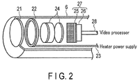
- the observation window (cover glass) 21 comprising an objective lens in the distal end face, and arranged along the optical axis direction of the observation window 21 is an annular-shaped fog prevention heater 22, an imaging optical system 24 comprising lens groups, an image pickup device 25, and an image processing section 26.
- the image pickup device 25 photoelectrically converts an observation optical image formed on an imaging surface to generate a video signal. It is possible to use, as the image pickup device 25, for example, a CCD or a CMOS image sensor in which multiple image pickup devices are arranged in a plane (in matrix form) so that at least addresses can be identified.
- the image pickup device 25 is disposed integrally with the image processing section 26, and constitutes an imaging unit 27.
- the fog prevention heater 22 is annular-shaped to ensure the optical path of the observation window 21, is located close to the circumferential portion of the observation window 21, or is in abutment with the circumferential portion of the observation window 21 via a heat conducting member, and is disposed to raise the temperature toward the center of the lens from the lens circumferential side.
- the fog prevention heater 22 is made of a highly resistant material, and generates heat due to electrical conduction.
- the fog prevention heater 22 is electrically insulated with an insulating member intervening between the fog prevention heater 22 and the inner surface of the distal end 6.
- a fog prevention operation suggests an operation of preventing or removing the fog on the observation window.
- the observation image which has passed through the observation window 21 is focused by the imaging optical system 24 on the imaging surface of the image pickup device 25 disposed in the rear on the optical axis, photoelectrically converted into an electric signal, and generated as an imaging signal by the image processing section 26.
- This imaging signal is sent to the video processor 9 through a video signal wiring line 28 (and the universal cable 14).
- the video processor 9 subjects the imaging signal to predetermined image processing, and outputs the signal to the monitor 10.
- FIG. 3 is a diagram showing the block configuration for controlling the fog prevention operation for the objective lens in the distal end 6.
- components for performing the fog prevention operation in the present embodiment are selectively shown, and components which are not shown but which are provided in a general video processor are considered to be installed.
- the video processor 9 comprises an image processing section 31 which removes noise from the imaging signal and performs amplification, a luminance level detection circuit 32 which detects a distribution obtained by the luminance level of the imaging signal, a video signal processing circuit 33 which generates a video signal for monitor display, a determination standard setting unit 34 which sets a determination standard, a memory 35 which stores determination standards, a determination circuit 36 which determines whether to turn on or off the fog prevention heater 22 based on the determination standard, a heater power supply 37 which outputs electric power to be supplied to the fog prevention heater 22, and an electric power supply circuit 38 which supplies electric power to the fog prevention heater 22 in accordance with the determination result.
- the contrast level (luminance distribution) of an obtained video signal is changed by whether or not the surface of the observation window 21 has fogged up.
- the luminance distribution of a video signal is wide (the contrast is high) in the case where the observation window 21 has not fogged up, and a proper observation image has entered the image pickup device 25.
- the luminance distribution of a video signal is narrow (the overall contrast is low) in the case where the observation window 21 has fogged up, and a dimmed observation image has entered the image capture device 25.
- the image processing section 31 has a filter circuit, an amplification circuit, and others, and the image processing section 31 performs noise reduction and amplification processing for the imaging signal received from the imaging unit 27 disposed at the distal end.
- the luminance level detection circuit 32 detects a distribution obtained by the luminance level of the imaging signal shown in FIG. 5 , which will be described later.
- the video signal processing circuit 33 processes the imaging signal output from the image processing section 31 into a video signal to be displayed on the monitor 10.
- the memory 35 stores the determination standards, which will be described later, as a table or parameters. It should be understood that the memory 35 may be used as a single memory, or a memory attached to a control section (e.g. a personal computer) for controlling an endoscopic system may be used.
- the determination standard setting unit 34 sets a determination standard selected by a selection switch (not shown in the drawings).
- the determination standard is set, for example, by selecting a later-described observation field displayed on the monitor 10.
- the determination circuit 36 compares the detected distribution of the luminance level (or referred to as a luminance distribution) with the set determination standard serving as a threshold, and thereby determines whether or not to raise the temperature of the fog prevention heater 22. This determination continues during the observation operation, and detection and determination by comparison are successively performed at predetermined time intervals.
- the observation window 21 is determined to have fogged up below the value of the width (luminance range b: b% shown in FIG. 5 ) of the distribution centering at the peak value of the distribution of the luminance level in the comparison, or above a preset threshold (a% shown in FIG. 5 ). These determinations may be made by one of the width of the distribution or the threshold, or may use both the width of the distribution and the threshold as the determination standards.
- the set values of a and b set in the determination standard setting unit 34 are numerical values that vary depending on the design and structure of the insertion portion, and a weight can be set for each of the later-described observation fields. Empirically, the set value can be set to a height of about 50% of the overall luminance.
- the set value of b can be set to, for example, a width of about 50% to 70%.
- the peak of the luminance level shown in FIG. 5 is not exclusively the central position of the detected luminance range.
- the electric power supply circuit 38 supplies electric power to the fog prevention heater 22 from the heater power supply 37 in accordance with the determination result in the determination circuit 36, and raises the temperature of the observation window 21 to about 40°C or less to remove the fog. If the fog on the observation window 21 is removed, the distribution of the luminance level changes to the characteristic shown in FIG. 4 , and the distributed luminance level becomes higher.
- the observation with an endoscope varies according to an observation target depending on whether to watch the screen central side or screen peripheral side in a display screen appearing on the monitor 10.
- a fog position luminance change position
- the weighting in the present embodiment is classified by the fields (parts) of the observation target as below.
- the inside of the lumen is mainly observed, so that an observer mainly watches the peripheral part of the display screen (visual field mask).
- the observation target is the peripheral part of the display screen.
- the pixels on the peripheral side of the imaging surface rather than the pixels on the central side are weighted, as shown in FIG. 6B .
- Whether the observation window 21 has fogged up is detected on the basis of the luminance level (contrast value) of an image signal acquired from the pixels for imaging color parts on the wall surface of the lumen.
- the distal end may be bent to take an extensive view of the inside of the cavity.
- a visual field to be obtained can be caught on the central side of the display screen, and it is therefore desirable that the central side of the observation window 21 not fog up.
- the pixels on the central side of the imaging surface rather than the pixels on the peripheral side are weighted. That is, the weighting is reverse to that in [Selection 1].
- the large intestine is in the lumen, but is a winding organ. Both the peripheral side and the central side of the display screen need to be observed, and it is desirable that the whole visual field not fog up. Thus, it is desirable that the whole surface of the observation window 21 not fog up, so that the pixels on the imaging surface are not independently weighted.
- the cavity In the case of an operation on the lung or the esophagus (chest cavity), the cavity is deep, and there are many instances where the visual field is deep. The depth is great, and the operative field is therefore captured on the entire screen, so it is desirable that the entire surface of the observation window 21 not fog up at all. Thus, the pixels on the imaging surface are not independently weighted.
- the depth is not as great as that in the chest cavity, and the observation target (operative field and location) to be observed by the observer can be caught on the central side of the display screen. Therefore, it is desirable that the central side of the observation window 21 not fog up, and the pixels on the central side of the imaging surface rather than the pixels on the peripheral side are weighted. The weighting similar to the above-mentioned weighting in [Selection 2] is performed.
- the cavity is extremely narrow, and the operative field therefore needs to be caught on the entire screen, so that it is desirable that the entire surface of the observation window 21 not fog up at all.
- the pixels on the imaging surface are not independently weighted.
- the cavity is narrow but long, and the whole operative field is therefore caught on the entire screen, so that it is desirable that the entire surface of the observation window 21 not fog up at all.
- the pixels on the imaging surface are not independently weighted.
- the entire color of a taken observation picture becomes lighter, and the level of the luminance becomes lower, or a peak is generated in the luminance of a part of the entire display screen so that the distribution of the luminance level becomes narrower and the contrast becomes lower.
- This characteristic is used to compare the distribution or threshold of the luminance level of a taken observation image with the determination standard comprising a predetermined distribution of the luminance level or a predetermined threshold ( FIG. 5 ) when the contrast of the photographic image has decreased. If the observation image is lower than the determination standard as a result of the comparison, it is determined that the observation window 21 has fogged up, and electric power is supplied to the fog prevention heater 22 so that the temperature of the observation window 21 is raised.
- the distribution (contrast) of the luminance level of the photographic image can be used to determine whether the observation window has fogged up, and the fog can be removed by raising the temperature of the heater.
- the configuration without the temperature sensor enables reducing the diameter of the distal end of the insertion portion and reduces the number of components, and is therefore advantageous in manufacturing costs.
- the present modification provides a configuration equivalent to that of the endoscopic system shown in FIG. 1 and FIG. 2 according to the first embodiment described above, and is different in temperature control.
- the same components are described below with the same reference signs.
- the fog that is formed on the observation window when the insertion portion is inserted in the lumen is removed.
- the present modification describes the operation of preventing the fog on the observation window 21 before the insertion portion 4 is inserted into the lumen, and in the situation in which the insertion portion 4 is taken out of the lumen during the observation and again inserted into the lumen.
- the temperature of the distal end 6 of the insertion portion 4 is closer to the outdoor air temperature.
- the difference between the temperature of the observation window at the distal end and the temperature inside the lumen is also great.
- the probability that the observation window fogs up is higher.
- the imaging unit 27 captures images of a space having no light-emitting objects without facing any article.
- a taken observation image is darker than normal and is lower in luminance level, that is, lower in contrast because reflected light from the article which is illuminated by illumination light does not enter the image capture device 25.
- the determination circuit 36 compares the luminance level of the observation image with the determination standard, and determines that the observation window 21 has fogged up because the contrast is low.
- the electric power supply circuit 38 supplies electric power to the fog prevention heater 22 from the heater power supply 37, and raises the temperature of the observation window 21. As a result, the temperature of the observation window 21 increases, and the temperature difference between the observation window 21 and the temperature inside the lumen is reduced.
- the same also applies to the situation in which the insertion portion 4 is taken out of the lumen during the observation and again inserted into the lumen. That is, if the insertion portion 4 is taken out of the lumen during the observation, the temperature of the observation window 21 at the distal end 6 also decreases closer to the outdoor air temperature, and the temperature difference between the observation window 21 and the temperature inside the lumen increases. If the imaging continues when the insertion portion 4 is taken out, an image of the space is captured, and an observation image low in luminance level, that is, low in contrast is taken because the space is captured, as described above. Therefore, it is determined that the observation window 21 has fogged up, and the electric power supply circuit 38 supplies electric power to the fog prevention heater 22, and raises the temperature of the observation window 21.
- an imaging operation is performed at the start of observation and before insertion, so that the temperature of the observation window 21 can be raised, and the temperature difference between the temperature of the observation window 21 and the temperature inside the lumen is eliminated before insertion, whereby the fog on the observation window 21 can be prevented.
- the imaging operation is continued when the distal end 6 is taken out of the lumen during the observation, the temperature of the observation window 21 can be raised, and the increase of the difference between the temperature of the observation window 21 and the temperature inside the lumen can be prevented.
- the prevention of the increase of the temperature difference it is possible to prevent the fog on the observation window when the distal end 6 of the insertion portion 4 is again inserted into the lumen.
- a temperature sensor is not installed in the distal end of an insertion portion and which detects the state of fogging from a taken image and controls temperature raising of a heater.
Landscapes
- Health & Medical Sciences (AREA)
- Life Sciences & Earth Sciences (AREA)
- Physics & Mathematics (AREA)
- Surgery (AREA)
- Optics & Photonics (AREA)
- Engineering & Computer Science (AREA)
- Biomedical Technology (AREA)
- Veterinary Medicine (AREA)
- Biophysics (AREA)
- Pathology (AREA)
- Radiology & Medical Imaging (AREA)
- Nuclear Medicine, Radiotherapy & Molecular Imaging (AREA)
- Public Health (AREA)
- Heart & Thoracic Surgery (AREA)
- Medical Informatics (AREA)
- Molecular Biology (AREA)
- Animal Behavior & Ethology (AREA)
- General Health & Medical Sciences (AREA)
- General Physics & Mathematics (AREA)
- Signal Processing (AREA)
- Astronomy & Astrophysics (AREA)
- Multimedia (AREA)
- Endoscopes (AREA)
- Instruments For Viewing The Inside Of Hollow Bodies (AREA)
- Closed-Circuit Television Systems (AREA)
Abstract
Description
- The present invention relates to an endoscopic system having a fog prevention function of an observation window in an insertion portion of an endoscope.
- In general, an observation window disposed at the distal end of an insertion portion of an endoscope is at a temperature equal to an outside ambient temperature of, for example, approximately 25°C before being inserted into a lumen that is an observation target. The environment inside the lumen is at a temperature of approximately 37°C and at a humidity of nearly 100%. Thus, if moisture in the lumen adheres to the surface of a lens and generates fog or waterdrops thereupon due to a temperature difference between the temperature of the lens of the observation window and the temperature inside the lumen at the time of insertion, an observation image becomes difficult to view. For example, a configuration known as a technique for removing the fog injects a cleaning fluid from an injection hole disposed in the vicinity of the observation window to remove the fog. However, the observation window again fogs up if its temperature is low.
- Thus, for example, Jpn. Pat. Appln. KOKAI Publication No.
2006-282 Patent Literature 1, a temperature sensor for controlling the temperature of the heater is disposed in the distal end of an insertion portion in the vicinity of the heater, in addition to an electric power supply wire laid for supplying electricity to the heater, and a communication wire laid for acquiring temperature information. - As disclosed in Jpn. Pat. Appln. KOKAI Publication No.
2006-282 - However, the temperature sensor is installed at the distal end of the insertion portion, so that the presence of the temperature sensor is a problem for a further reduction in the diameter of the insertion portion.
- It is therefore an object of the present invention to provide an endoscopic system in which a temperature sensor is not installed in the distal end of an insertion portion, and which detects the state of fogging from a taken image and suitably controls raising the temperature of a heater to an observation target.
- According to an embodiment of the present invention, there is provided an endoscopic system comprising: an endoscope in which an observation window is disposed at a distal end and which has an insertion portion to be inserted into a lumen; an imaging unit having an imaging surface comprising pixels to convert, into an image signal, an observation image which is focused through the observation window; a fog prevention heater disposed in the vicinity of the observation window; a luminance level detection section which detects the distribution of a luminance level resulting from the image signal output by the pixels of the imaging unit; a determination section which compares the distribution of the luminance level with a preset first determination standard and further compares the distribution of the luminance level with a threshold that is a preset second determination standard, and makes a determination so that the fog prevention heater performs a temperature raising operation on the basis of the comparisons; and a heater power supply which drives the fog prevention heater to raise the temperature of the observation window in accordance with the determination result in the determination section.
-
-
FIG. 1 is a diagram showing an overall configuration example of an endoscopic apparatus having an imaging unit in an endoscopic body as a medical instrument of the present invention; -
FIG. 2 is a sectional view showing the internal structure of the distal end of the endoscopic body; -
FIG. 3 is a block diagram showing the configuration of a video processor; -
FIG. 4 is a graph showing an example of the distribution of a luminance level in the case where an observation window has not fogged up; -
FIG. 5 is a graph showing an example of the distribution of a luminance level in the case where the observation window has fogged up; -
FIG. 6A is a diagram showing an example illustrating the weighting of pixels in a light receiving surface of an image pickup device; and -
FIG. 6B is a diagram showing an example illustrating the weighting of the pixels in the light receiving surface of the image pickup device. - Hereinafter, an embodiment of the present invention is described in detail with reference to the drawings.
-
FIG. 1 is a diagram showing an overall configuration example of an endoscopic system having a fog prevention configuration in the distal end of an insertion portion as a medical instrument of the present invention. - An endoscopic apparatus according to the present embodiment generally comprises an
endoscopic body 1, and anendoscopic instrument 7 serving as various external devices mounted on amovable trolley 2. Although a flexible scope is described below by way of example, a rigid scope can also be mounted. - The
endoscopic body 1 comprises an insertion portion (flexible tube) 4 which is inserted into a body cavity that is an observation target, abending portion 5, and a later-describeddistal end 6 provided on the distal side of theinsertion portion 4, and an endoscopic operation portion 3 which is provided on the proximal side and which is operated to bend thebending portion 5. In the following explanation, the side of thebending portion 5 is referred to as the distal side, and the side of the operation portion 3 is referred to as the proximal side. - The
endoscopic instrument 7 has alight source device 8 which generates illumination light to be applied to an observation target part, avideo processor 9 which subjects a captured video signal to predetermined image processing, amonitor 10 which displays the video signal as an observation image, and akeyboard 11 or the like which is an input section. - Furthermore, a
bottle 12 which retains a fluid used for cleaning, etc. (cleaning fluid: a fluid mainly containing water such as a physiological saline solution, etc.) is removably attached to thetrolley 2. Theendoscopic instrument 7 includes an air supply pump unit (not shown). Moreover, asuction unit 13 which sucks a fluid or gas injected from a later-described cleaning nozzle in the body cavity and mucus is stored on a shelf of thetrolley 2. - The
endoscopic body 1 and thelight source device 8 are connected to each other by aconnector 15 via auniversal cable 14. Theuniversal cable 14 not only includes a light guide comprising optical fibers, but also includes signal wires which transmit video signals, and a supply path (gas/fluid supply channel) and a discharge path comprising tubes for the gas and fluid. Theconnector 15 connected to theuniversal cable 14 on the side of theendoscopic instrument 7 branches into a signal line, a tube, and a light guide which are respectively connected to thevideo processor 9, thesuction unit 13, and thelight source device 8. The endoscopic operation portion 3 is provided with abending operation portion 16 for bending thebending portion 5, for example, in vertical and horizontal directions which intersect at right angles with each other relative to the insertion direction, a gas/fluid supply button 17a, and asuction operation button 17b. An insertion opening 18 of a forceps channel which passes through theinsertion portion 4 from a channel opening disposed at the distal end is provided on the proximal side of theinsertion portion 4 between theinsertion portion 4 and the endoscopic operation portion 3. - The
distal end 6 of theendoscopic body 1 is formed into a circular cylindrical shape by a rigid material, and is provided, in the distal end face, with an illumination window to apply at least illumination light, and anobservation window 21 to observe the observation target part. Although not shown, a nozzle for injecting the fluid is disposed in the vicinity of the observation window on the distal end face. The observation window is configured by an optical lens, and applies to the observation target part the illumination light which has been guided from thelight source device 8 through the optical fiber. - As shown in
FIG. 2 , arranged in thedistal end 6 is the observation window (cover glass) 21 comprising an objective lens in the distal end face, and arranged along the optical axis direction of theobservation window 21 is an annular-shapedfog prevention heater 22, an imagingoptical system 24 comprising lens groups, animage pickup device 25, and animage processing section 26. Theimage pickup device 25 photoelectrically converts an observation optical image formed on an imaging surface to generate a video signal. It is possible to use, as theimage pickup device 25, for example, a CCD or a CMOS image sensor in which multiple image pickup devices are arranged in a plane (in matrix form) so that at least addresses can be identified. Theimage pickup device 25 is disposed integrally with theimage processing section 26, and constitutes animaging unit 27. - The
fog prevention heater 22 is annular-shaped to ensure the optical path of theobservation window 21, is located close to the circumferential portion of theobservation window 21, or is in abutment with the circumferential portion of theobservation window 21 via a heat conducting member, and is disposed to raise the temperature toward the center of the lens from the lens circumferential side. Thefog prevention heater 22 is made of a highly resistant material, and generates heat due to electrical conduction. When thedistal end 6 is made of a metallic material, thefog prevention heater 22 is electrically insulated with an insulating member intervening between thefog prevention heater 22 and the inner surface of thedistal end 6. In the following explanation, a fog prevention operation suggests an operation of preventing or removing the fog on the observation window. - In such a configuration, the observation image which has passed through the
observation window 21 is focused by the imagingoptical system 24 on the imaging surface of theimage pickup device 25 disposed in the rear on the optical axis, photoelectrically converted into an electric signal, and generated as an imaging signal by theimage processing section 26. This imaging signal is sent to thevideo processor 9 through a video signal wiring line 28 (and the universal cable 14). Thevideo processor 9 subjects the imaging signal to predetermined image processing, and outputs the signal to themonitor 10. -
FIG. 3 is a diagram showing the block configuration for controlling the fog prevention operation for the objective lens in thedistal end 6. InFIG. 3 , components for performing the fog prevention operation in the present embodiment are selectively shown, and components which are not shown but which are provided in a general video processor are considered to be installed. - The
video processor 9 according to the present embodiment comprises animage processing section 31 which removes noise from the imaging signal and performs amplification, a luminancelevel detection circuit 32 which detects a distribution obtained by the luminance level of the imaging signal, a videosignal processing circuit 33 which generates a video signal for monitor display, a determinationstandard setting unit 34 which sets a determination standard, amemory 35 which stores determination standards, adetermination circuit 36 which determines whether to turn on or off thefog prevention heater 22 based on the determination standard, aheater power supply 37 which outputs electric power to be supplied to thefog prevention heater 22, and an electricpower supply circuit 38 which supplies electric power to thefog prevention heater 22 in accordance with the determination result. - The fog prevention operation for the observation window according to the present embodiment is described.
- Normally, the contrast level (luminance distribution) of an obtained video signal is changed by whether or not the surface of the
observation window 21 has fogged up. For example, in the example of a feature shown inFIG. 4 , the luminance distribution of a video signal is wide (the contrast is high) in the case where theobservation window 21 has not fogged up, and a proper observation image has entered theimage pickup device 25. In the example of a feature shown inFIG. 5 , the luminance distribution of a video signal is narrow (the overall contrast is low) in the case where theobservation window 21 has fogged up, and a dimmed observation image has entered theimage capture device 25. - In the configuration according to the present embodiment, the
image processing section 31 has a filter circuit, an amplification circuit, and others, and theimage processing section 31 performs noise reduction and amplification processing for the imaging signal received from theimaging unit 27 disposed at the distal end. The luminancelevel detection circuit 32 detects a distribution obtained by the luminance level of the imaging signal shown inFIG. 5 , which will be described later. The videosignal processing circuit 33 processes the imaging signal output from theimage processing section 31 into a video signal to be displayed on themonitor 10. Thememory 35 stores the determination standards, which will be described later, as a table or parameters. It should be understood that thememory 35 may be used as a single memory, or a memory attached to a control section (e.g. a personal computer) for controlling an endoscopic system may be used. - The determination
standard setting unit 34 sets a determination standard selected by a selection switch (not shown in the drawings). The determination standard is set, for example, by selecting a later-described observation field displayed on themonitor 10. Thedetermination circuit 36 compares the detected distribution of the luminance level (or referred to as a luminance distribution) with the set determination standard serving as a threshold, and thereby determines whether or not to raise the temperature of thefog prevention heater 22. This determination continues during the observation operation, and detection and determination by comparison are successively performed at predetermined time intervals. - In this determination, the
observation window 21 is determined to have fogged up below the value of the width (luminance range b: b% shown inFIG. 5 ) of the distribution centering at the peak value of the distribution of the luminance level in the comparison, or above a preset threshold (a% shown inFIG. 5 ). These determinations may be made by one of the width of the distribution or the threshold, or may use both the width of the distribution and the threshold as the determination standards. The set values of a and b set in the determinationstandard setting unit 34 are numerical values that vary depending on the design and structure of the insertion portion, and a weight can be set for each of the later-described observation fields. Empirically, the set value can be set to a height of about 50% of the overall luminance. The set value of b can be set to, for example, a width of about 50% to 70%. The peak of the luminance level shown inFIG. 5 is not exclusively the central position of the detected luminance range. - The electric
power supply circuit 38 supplies electric power to thefog prevention heater 22 from theheater power supply 37 in accordance with the determination result in thedetermination circuit 36, and raises the temperature of theobservation window 21 to about 40°C or less to remove the fog. If the fog on theobservation window 21 is removed, the distribution of the luminance level changes to the characteristic shown inFIG. 4 , and the distributed luminance level becomes higher. - In general, the observation with an endoscope varies according to an observation target depending on whether to watch the screen central side or screen peripheral side in a display screen appearing on the
monitor 10. In the present embodiment, a fog position (luminance change position) is weighted by the position on the display screen (imaging surface) to be watched, that is, the position (address) of a pixel. The weighting in the present embodiment is classified by the fields (parts) of the observation target as below. - The inside of the lumen is mainly observed, so that an observer mainly watches the peripheral part of the display screen (visual field mask). For example, as shown in
FIG. 6A , in the case of a bronchus, the observation target is the peripheral part of the display screen. In the case of such an organ, the pixels on the peripheral side of the imaging surface rather than the pixels on the central side are weighted, as shown inFIG. 6B . Whether theobservation window 21 has fogged up is detected on the basis of the luminance level (contrast value) of an image signal acquired from the pixels for imaging color parts on the wall surface of the lumen. - In the case of the stomach, the distal end may be bent to take an extensive view of the inside of the cavity. A visual field to be obtained can be caught on the central side of the display screen, and it is therefore desirable that the central side of the
observation window 21 not fog up. Thus, the pixels on the central side of the imaging surface rather than the pixels on the peripheral side are weighted. That is, the weighting is reverse to that in [Selection 1]. - The large intestine is in the lumen, but is a winding organ. Both the peripheral side and the central side of the display screen need to be observed, and it is desirable that the whole visual field not fog up. Thus, it is desirable that the whole surface of the
observation window 21 not fog up, so that the pixels on the imaging surface are not independently weighted. - In the case of an operation on the lung or the esophagus (chest cavity), the cavity is deep, and there are many instances where the visual field is deep. The depth is great, and the operative field is therefore captured on the entire screen, so it is desirable that the entire surface of the
observation window 21 not fog up at all. Thus, the pixels on the imaging surface are not independently weighted. - In the case of an operation on the stomach or the large intestine (abdominal cavity), the depth is not as great as that in the chest cavity, and the observation target (operative field and location) to be observed by the observer can be caught on the central side of the display screen. Therefore, it is desirable that the central side of the
observation window 21 not fog up, and the pixels on the central side of the imaging surface rather than the pixels on the peripheral side are weighted. The weighting similar to the above-mentioned weighting in [Selection 2] is performed. - In the case of arthroscopy, the cavity is extremely narrow, and the operative field therefore needs to be caught on the entire screen, so that it is desirable that the entire surface of the
observation window 21 not fog up at all. Thus, the pixels on the imaging surface are not independently weighted. - In the case of an endoscopic paranasal sinus operation, the cavity is narrow but long, and the whole operative field is therefore caught on the entire screen, so that it is desirable that the entire surface of the
observation window 21 not fog up at all. Thus, the pixels on the imaging surface are not independently weighted. - As described above, according to the present embodiment, when the observation window at the distal end of the endoscope has fogged up due to a temperature difference and humidity, the entire color of a taken observation picture becomes lighter, and the level of the luminance becomes lower, or a peak is generated in the luminance of a part of the entire display screen so that the distribution of the luminance level becomes narrower and the contrast becomes lower. This characteristic is used to compare the distribution or threshold of the luminance level of a taken observation image with the determination standard comprising a predetermined distribution of the luminance level or a predetermined threshold (
FIG. 5 ) when the contrast of the photographic image has decreased. If the observation image is lower than the determination standard as a result of the comparison, it is determined that theobservation window 21 has fogged up, and electric power is supplied to thefog prevention heater 22 so that the temperature of theobservation window 21 is raised. - Therefore, according to the present embodiment, even if a temperature sensor that has heretofore been disposed in the distal end of the endoscope is not provided, the distribution (contrast) of the luminance level of the photographic image can be used to determine whether the observation window has fogged up, and the fog can be removed by raising the temperature of the heater. The configuration without the temperature sensor enables reducing the diameter of the distal end of the insertion portion and reduces the number of components, and is therefore advantageous in manufacturing costs.
- Next, a modification of the first embodiment is described. The present modification provides a configuration equivalent to that of the endoscopic system shown in
FIG. 1 andFIG. 2 according to the first embodiment described above, and is different in temperature control. The same components are described below with the same reference signs. In the first embodiment described above, the fog that is formed on the observation window when the insertion portion is inserted in the lumen is removed. - The present modification describes the operation of preventing the fog on the
observation window 21 before theinsertion portion 4 is inserted into the lumen, and in the situation in which theinsertion portion 4 is taken out of the lumen during the observation and again inserted into the lumen. - First, when the temperature difference between the outdoor air temperature and the temperature inside the lumen is great under the usage environment, the temperature of the
distal end 6 of theinsertion portion 4 is closer to the outdoor air temperature. Thus, the difference between the temperature of the observation window at the distal end and the temperature inside the lumen is also great. Thus, if the insertion portion is inserted into the lumen as it is, the probability that the observation window fogs up is higher. - Thus, under an external environment before the start of insertion, the
imaging unit 27 captures images of a space having no light-emitting objects without facing any article. When the space is simply captured, a taken observation image is darker than normal and is lower in luminance level, that is, lower in contrast because reflected light from the article which is illuminated by illumination light does not enter theimage capture device 25. As described above, thedetermination circuit 36 compares the luminance level of the observation image with the determination standard, and determines that theobservation window 21 has fogged up because the contrast is low. In accordance with this determination, the electricpower supply circuit 38 supplies electric power to thefog prevention heater 22 from theheater power supply 37, and raises the temperature of theobservation window 21. As a result, the temperature of theobservation window 21 increases, and the temperature difference between theobservation window 21 and the temperature inside the lumen is reduced. - Therefore, it is difficult for the
observation window 21 to fog up when thedistal end 6 is inserted into the lumen. - The same also applies to the situation in which the
insertion portion 4 is taken out of the lumen during the observation and again inserted into the lumen. That is, if theinsertion portion 4 is taken out of the lumen during the observation, the temperature of theobservation window 21 at thedistal end 6 also decreases closer to the outdoor air temperature, and the temperature difference between theobservation window 21 and the temperature inside the lumen increases. If the imaging continues when theinsertion portion 4 is taken out, an image of the space is captured, and an observation image low in luminance level, that is, low in contrast is taken because the space is captured, as described above. Therefore, it is determined that theobservation window 21 has fogged up, and the electricpower supply circuit 38 supplies electric power to thefog prevention heater 22, and raises the temperature of theobservation window 21. - As described above, according to the present modification, an imaging operation is performed at the start of observation and before insertion, so that the temperature of the
observation window 21 can be raised, and the temperature difference between the temperature of theobservation window 21 and the temperature inside the lumen is eliminated before insertion, whereby the fog on theobservation window 21 can be prevented. Similarly, if the imaging operation is continued when thedistal end 6 is taken out of the lumen during the observation, the temperature of theobservation window 21 can be raised, and the increase of the difference between the temperature of theobservation window 21 and the temperature inside the lumen can be prevented. As a result of the prevention of the increase of the temperature difference, it is possible to prevent the fog on the observation window when thedistal end 6 of theinsertion portion 4 is again inserted into the lumen. - According to the present invention, it is possible to provide an endoscopic system in which a temperature sensor is not installed in the distal end of an insertion portion and which detects the state of fogging from a taken image and controls temperature raising of a heater.
Claims (6)
- An endoscopic system characterized by comprising:an endoscope in which an observation window is disposed at a distal end and which has an insertion portion to be inserted into a lumen;an imaging unit having an imaging surface comprising pixels to convert, into an image signal, an observation image which is focused through the observation window;a fog prevention heater disposed in the vicinity of the observation window;a luminance level detection section which detects the distribution of a luminance level resulting from the image signal output by the pixels of the imaging unit;a determination section which compares the distribution of the luminance level with a preset determination standard and makes a determination so that the fog prevention heater performs a temperature raising operation when the distribution of the luminance level is less than or equal to the determination standard; anda heater power supply which drives the fog prevention heater to raise the temperature of the observation window in accordance with the determination result in the determination section.
- The endoscopic system according to claim 1, characterized in that a range of a distribution centering at a peak value of the distribution of the luminance level is further set as a first determination standard.
- The endoscopic system according to claim 1 or 2, characterized in that a threshold for the luminance level output by the pixels is set as a second determination standard.
- The endoscopic system according to claim 1, characterized by further comprising a determination standard setting section which sets, as a determination standard, the distribution of the luminance level detected from the pixels weighted at a position on the imaging surface in accordance with a desired observation target that is to be observed.
- The endoscopic system according to claim 1, characterized in that the determination section successively performs detection and determination by comparison at predetermined time intervals throughout an observation operation.
- The endoscopic system according to claim 4, characterized in that regarding the weighting at the position on the imaging surface,a. the pixels on the central side of the imaging surface are weighted when the center of a display screen in the observation target is watched,b. the pixels on the peripheral side of the imaging surface are weighted when the peripheral side of the display screen in the observation target is watched, andc. the pixels on the imaging surface are not weighted when the entire display screen in the observation target is watched.
Applications Claiming Priority (2)
| Application Number | Priority Date | Filing Date | Title |
|---|---|---|---|
| JP2013214128 | 2013-10-11 | ||
| PCT/JP2014/077164 WO2015053387A1 (en) | 2013-10-11 | 2014-10-10 | Endoscope system |
Publications (3)
| Publication Number | Publication Date |
|---|---|
| EP3056133A1 true EP3056133A1 (en) | 2016-08-17 |
| EP3056133A4 EP3056133A4 (en) | 2017-06-07 |
| EP3056133B1 EP3056133B1 (en) | 2018-12-05 |
Family
ID=52813200
Family Applications (1)
| Application Number | Title | Priority Date | Filing Date |
|---|---|---|---|
| EP14853067.8A Active EP3056133B1 (en) | 2013-10-11 | 2014-10-10 | Endoscopic system |
Country Status (5)
| Country | Link |
|---|---|
| US (1) | US9642516B2 (en) |
| EP (1) | EP3056133B1 (en) |
| JP (1) | JP5781250B1 (en) |
| CN (1) | CN105377105B (en) |
| WO (1) | WO2015053387A1 (en) |
Families Citing this family (15)
| Publication number | Priority date | Publication date | Assignee | Title |
|---|---|---|---|---|
| WO2017185243A1 (en) * | 2016-04-27 | 2017-11-02 | 周永建 | Electric-heated anti-fogging laparoscope camera |
| AU2017313120B2 (en) | 2016-08-16 | 2022-12-01 | Donaldson Company, Inc. | Hydrocarbon fluid-water separation |
| CN109843209B (en) * | 2016-10-14 | 2023-04-18 | 直观外科手术操作公司 | Image capturing apparatus with reduced fog |
| CN110337260B (en) * | 2017-03-30 | 2022-03-25 | Hoya株式会社 | Electronic endoscope device |
| FR3067131B1 (en) * | 2017-06-01 | 2019-06-21 | Aptiv Technologies Limited | OPTICAL DEVICE FOR VEHICLE COMPRISING A HEATING ELEMENT |
| CN108652675A (en) * | 2018-02-11 | 2018-10-16 | 江苏金羿智芯科技有限公司 | A kind of endoscopic images defogging system based on artificial intelligence |
| CN108288257A (en) * | 2018-02-11 | 2018-07-17 | 江苏金羿智芯科技有限公司 | A kind of endoscopic images defogging method based on artificial intelligence |
| CA3089207A1 (en) | 2018-02-15 | 2019-08-22 | Donaldson Company, Inc. | Filter media configurations |
| KR20200119307A (en) | 2018-02-15 | 2020-10-19 | 도날드슨 컴파니, 인코포레이티드 | Filter element configuration |
| US11510561B2 (en) * | 2018-08-21 | 2022-11-29 | Verily Life Sciences Llc | Endoscope defogging |
| CN111489296A (en) * | 2019-01-29 | 2020-08-04 | 杭州海康慧影科技有限公司 | Endoscope image defogging method and device and electronic equipment |
| EP4461205B1 (en) * | 2019-08-22 | 2026-01-21 | Intuitive Surgical Operations, Inc. | Systems and methods for detecting physical contact of a surgical instrument with patient tissue |
| CN112954142B (en) * | 2019-11-22 | 2022-06-28 | 宝山钢铁股份有限公司 | A kind of intelligent dust removal and defogging camera protective cover and intelligent identification method thereof |
| KR20220097825A (en) * | 2020-12-31 | 2022-07-08 | 주식회사 이루다 | Laser device for laser treatment of skin lesions under dermal vasoconstriction |
| CN116421126B (en) * | 2023-06-07 | 2023-08-25 | 南京诺源医疗器械有限公司 | Feedback image depth analysis method and system for laparoscopic defogging pretreatment |
Family Cites Families (16)
| Publication number | Priority date | Publication date | Assignee | Title |
|---|---|---|---|---|
| JPH11318810A (en) * | 1998-05-14 | 1999-11-24 | Olympus Optical Co Ltd | Endoscope fog removing system |
| US20050154262A1 (en) * | 2003-04-01 | 2005-07-14 | Banik Michael S. | Imaging system for video endoscope |
| JP2006000282A (en) | 2004-06-16 | 2006-01-05 | Olympus Corp | Fogging preventing device for endoscope and endoscope |
| US7479106B2 (en) * | 2004-09-30 | 2009-01-20 | Boston Scientific Scimed, Inc. | Automated control of irrigation and aspiration in a single-use endoscope |
| JP4758719B2 (en) * | 2005-09-28 | 2011-08-31 | 富士フイルム株式会社 | Electronic endoscope |
| JP4624484B2 (en) * | 2008-10-24 | 2011-02-02 | オリンパスメディカルシステムズ株式会社 | Endoscope insertion part |
| EP2311365B1 (en) * | 2008-11-11 | 2013-01-16 | Olympus Medical Systems Corp. | Imaging device and endoscope |
| US9352174B2 (en) * | 2008-12-30 | 2016-05-31 | St. Jude Medical, Atrial Fibrillation Division, Inc. | Ablation system with blood leakage minimization and tissue protective capabilities |
| DE102009017606A1 (en) * | 2009-04-16 | 2010-10-21 | Henke-Sass, Wolf Gmbh | Endoscope with electric heating system |
| US8485967B2 (en) * | 2010-03-31 | 2013-07-16 | Fujifilm Corporation | Endoscopic imaging device and endoscope apparatus having a configuration to prevent condensation |
| CN102762160B (en) * | 2010-06-17 | 2015-03-04 | 奥林巴斯医疗株式会社 | Ultrasound suction system and ultrasound suction method |
| JP5065538B2 (en) * | 2010-09-14 | 2012-11-07 | オリンパスメディカルシステムズ株式会社 | ENDOSCOPE SYSTEM AND METHOD OF OPERATING VISUAL DEFECT JUDGING SYSTEM |
| CN103002789B (en) * | 2010-09-22 | 2015-07-08 | 奥林巴斯医疗株式会社 | Temperature control device for endoscope |
| JP5412601B2 (en) * | 2011-12-07 | 2014-02-12 | オリンパスメディカルシステムズ株式会社 | Electronic endoscope |
| FR2988653B1 (en) | 2012-03-29 | 2016-08-26 | Faurecia Sieges Automobile | ADJUSTING A SEAT FOR A MOTOR VEHICLE |
| US11363938B2 (en) * | 2013-03-14 | 2022-06-21 | Ormco Corporation | Feedback control mechanism for adjustment of imaging parameters in a dental imaging system |
-
2014
- 2014-10-10 EP EP14853067.8A patent/EP3056133B1/en active Active
- 2014-10-10 CN CN201480040397.5A patent/CN105377105B/en active Active
- 2014-10-10 WO PCT/JP2014/077164 patent/WO2015053387A1/en not_active Ceased
- 2014-10-10 JP JP2015512827A patent/JP5781250B1/en active Active
-
2015
- 2015-11-30 US US14/954,109 patent/US9642516B2/en active Active
Also Published As
| Publication number | Publication date |
|---|---|
| EP3056133A4 (en) | 2017-06-07 |
| JPWO2015053387A1 (en) | 2017-03-09 |
| US9642516B2 (en) | 2017-05-09 |
| CN105377105B (en) | 2017-09-22 |
| EP3056133B1 (en) | 2018-12-05 |
| WO2015053387A1 (en) | 2015-04-16 |
| US20160081541A1 (en) | 2016-03-24 |
| JP5781250B1 (en) | 2015-09-16 |
| CN105377105A (en) | 2016-03-02 |
Similar Documents
| Publication | Publication Date | Title |
|---|---|---|
| EP3056133B1 (en) | Endoscopic system | |
| US8212862B2 (en) | Endoscope system | |
| US10524645B2 (en) | Method and system for eliminating image motion blur in a multiple viewing elements endoscope | |
| US9907462B2 (en) | Endoscope tip position visual indicator and heat management system | |
| US8197399B2 (en) | System and method for producing and improving images | |
| EP3096675B1 (en) | System for eliminating image motion blur in a multiple viewing elements endoscope | |
| CN105358042B (en) | Endoscope tip position visual detector and thermal management | |
| US8419631B2 (en) | Endoscope apparatus with forward viewing and side viewing | |
| CN101683266B (en) | Endoscope-shape detection device | |
| JP5702036B1 (en) | Endoscope system | |
| US20140012078A1 (en) | Accelorometer Based Endoscopic Light Source Safety System | |
| US11141053B2 (en) | Endoscope apparatus and control apparatus | |
| JPH02257926A (en) | Endoscope | |
| JP3034905B2 (en) | Electronic endoscope | |
| JP5288909B2 (en) | Endoscope system and switch | |
| CN219048416U (en) | Duodenal mirror | |
| JP2012147882A (en) | Image picking-up apparatus for endoscope | |
| JP2007014423A (en) | Endoscope device | |
| JPH04150826A (en) | Endoscope |
Legal Events
| Date | Code | Title | Description |
|---|---|---|---|
| PUAI | Public reference made under article 153(3) epc to a published international application that has entered the european phase |
Free format text: ORIGINAL CODE: 0009012 |
|
| 17P | Request for examination filed |
Effective date: 20160426 |
|
| AK | Designated contracting states |
Kind code of ref document: A1 Designated state(s): AL AT BE BG CH CY CZ DE DK EE ES FI FR GB GR HR HU IE IS IT LI LT LU LV MC MK MT NL NO PL PT RO RS SE SI SK SM TR |
|
| AX | Request for extension of the european patent |
Extension state: BA ME |
|
| RAP1 | Party data changed (applicant data changed or rights of an application transferred) |
Owner name: OLYMPUS CORPORATION |
|
| RAP1 | Party data changed (applicant data changed or rights of an application transferred) |
Owner name: OLYMPUS CORPORATION |
|
| RIN1 | Information on inventor provided before grant (corrected) |
Inventor name: YASUE, MASASHI |
|
| DAX | Request for extension of the european patent (deleted) | ||
| A4 | Supplementary search report drawn up and despatched |
Effective date: 20170510 |
|
| RIC1 | Information provided on ipc code assigned before grant |
Ipc: H04N 7/18 20060101ALI20170503BHEP Ipc: A61B 1/04 20060101ALI20170503BHEP Ipc: A61B 1/00 20060101AFI20170503BHEP Ipc: G02B 23/24 20060101ALI20170503BHEP |
|
| GRAP | Despatch of communication of intention to grant a patent |
Free format text: ORIGINAL CODE: EPIDOSNIGR1 |
|
| STAA | Information on the status of an ep patent application or granted ep patent |
Free format text: STATUS: GRANT OF PATENT IS INTENDED |
|
| INTG | Intention to grant announced |
Effective date: 20180628 |
|
| RIN1 | Information on inventor provided before grant (corrected) |
Inventor name: YASUE, MASASHI |
|
| GRAS | Grant fee paid |
Free format text: ORIGINAL CODE: EPIDOSNIGR3 |
|
| GRAA | (expected) grant |
Free format text: ORIGINAL CODE: 0009210 |
|
| STAA | Information on the status of an ep patent application or granted ep patent |
Free format text: STATUS: THE PATENT HAS BEEN GRANTED |
|
| AK | Designated contracting states |
Kind code of ref document: B1 Designated state(s): AL AT BE BG CH CY CZ DE DK EE ES FI FR GB GR HR HU IE IS IT LI LT LU LV MC MK MT NL NO PL PT RO RS SE SI SK SM TR |
|
| REG | Reference to a national code |
Ref country code: GB Ref legal event code: FG4D |
|
| REG | Reference to a national code |
Ref country code: CH Ref legal event code: EP |
|
| REG | Reference to a national code |
Ref country code: AT Ref legal event code: REF Ref document number: 1072014 Country of ref document: AT Kind code of ref document: T Effective date: 20181215 |
|
| REG | Reference to a national code |
Ref country code: IE Ref legal event code: FG4D |
|
| REG | Reference to a national code |
Ref country code: DE Ref legal event code: R096 Ref document number: 602014037599 Country of ref document: DE |
|
| REG | Reference to a national code |
Ref country code: NL Ref legal event code: MP Effective date: 20181205 |
|
| REG | Reference to a national code |
Ref country code: AT Ref legal event code: MK05 Ref document number: 1072014 Country of ref document: AT Kind code of ref document: T Effective date: 20181205 |
|
| REG | Reference to a national code |
Ref country code: LT Ref legal event code: MG4D |
|
| PG25 | Lapsed in a contracting state [announced via postgrant information from national office to epo] |
Ref country code: FI Free format text: LAPSE BECAUSE OF FAILURE TO SUBMIT A TRANSLATION OF THE DESCRIPTION OR TO PAY THE FEE WITHIN THE PRESCRIBED TIME-LIMIT Effective date: 20181205 Ref country code: LV Free format text: LAPSE BECAUSE OF FAILURE TO SUBMIT A TRANSLATION OF THE DESCRIPTION OR TO PAY THE FEE WITHIN THE PRESCRIBED TIME-LIMIT Effective date: 20181205 Ref country code: AT Free format text: LAPSE BECAUSE OF FAILURE TO SUBMIT A TRANSLATION OF THE DESCRIPTION OR TO PAY THE FEE WITHIN THE PRESCRIBED TIME-LIMIT Effective date: 20181205 Ref country code: HR Free format text: LAPSE BECAUSE OF FAILURE TO SUBMIT A TRANSLATION OF THE DESCRIPTION OR TO PAY THE FEE WITHIN THE PRESCRIBED TIME-LIMIT Effective date: 20181205 Ref country code: LT Free format text: LAPSE BECAUSE OF FAILURE TO SUBMIT A TRANSLATION OF THE DESCRIPTION OR TO PAY THE FEE WITHIN THE PRESCRIBED TIME-LIMIT Effective date: 20181205 Ref country code: BG Free format text: LAPSE BECAUSE OF FAILURE TO SUBMIT A TRANSLATION OF THE DESCRIPTION OR TO PAY THE FEE WITHIN THE PRESCRIBED TIME-LIMIT Effective date: 20190305 Ref country code: ES Free format text: LAPSE BECAUSE OF FAILURE TO SUBMIT A TRANSLATION OF THE DESCRIPTION OR TO PAY THE FEE WITHIN THE PRESCRIBED TIME-LIMIT Effective date: 20181205 Ref country code: NO Free format text: LAPSE BECAUSE OF FAILURE TO SUBMIT A TRANSLATION OF THE DESCRIPTION OR TO PAY THE FEE WITHIN THE PRESCRIBED TIME-LIMIT Effective date: 20190305 |
|
| PG25 | Lapsed in a contracting state [announced via postgrant information from national office to epo] |
Ref country code: AL Free format text: LAPSE BECAUSE OF FAILURE TO SUBMIT A TRANSLATION OF THE DESCRIPTION OR TO PAY THE FEE WITHIN THE PRESCRIBED TIME-LIMIT Effective date: 20181205 Ref country code: GR Free format text: LAPSE BECAUSE OF FAILURE TO SUBMIT A TRANSLATION OF THE DESCRIPTION OR TO PAY THE FEE WITHIN THE PRESCRIBED TIME-LIMIT Effective date: 20190306 Ref country code: RS Free format text: LAPSE BECAUSE OF FAILURE TO SUBMIT A TRANSLATION OF THE DESCRIPTION OR TO PAY THE FEE WITHIN THE PRESCRIBED TIME-LIMIT Effective date: 20181205 Ref country code: SE Free format text: LAPSE BECAUSE OF FAILURE TO SUBMIT A TRANSLATION OF THE DESCRIPTION OR TO PAY THE FEE WITHIN THE PRESCRIBED TIME-LIMIT Effective date: 20181205 |
|
| PG25 | Lapsed in a contracting state [announced via postgrant information from national office to epo] |
Ref country code: NL Free format text: LAPSE BECAUSE OF FAILURE TO SUBMIT A TRANSLATION OF THE DESCRIPTION OR TO PAY THE FEE WITHIN THE PRESCRIBED TIME-LIMIT Effective date: 20181205 |
|
| PG25 | Lapsed in a contracting state [announced via postgrant information from national office to epo] |
Ref country code: CZ Free format text: LAPSE BECAUSE OF FAILURE TO SUBMIT A TRANSLATION OF THE DESCRIPTION OR TO PAY THE FEE WITHIN THE PRESCRIBED TIME-LIMIT Effective date: 20181205 Ref country code: IT Free format text: LAPSE BECAUSE OF FAILURE TO SUBMIT A TRANSLATION OF THE DESCRIPTION OR TO PAY THE FEE WITHIN THE PRESCRIBED TIME-LIMIT Effective date: 20181205 Ref country code: PT Free format text: LAPSE BECAUSE OF FAILURE TO SUBMIT A TRANSLATION OF THE DESCRIPTION OR TO PAY THE FEE WITHIN THE PRESCRIBED TIME-LIMIT Effective date: 20190405 Ref country code: PL Free format text: LAPSE BECAUSE OF FAILURE TO SUBMIT A TRANSLATION OF THE DESCRIPTION OR TO PAY THE FEE WITHIN THE PRESCRIBED TIME-LIMIT Effective date: 20181205 |
|
| PG25 | Lapsed in a contracting state [announced via postgrant information from national office to epo] |
Ref country code: EE Free format text: LAPSE BECAUSE OF FAILURE TO SUBMIT A TRANSLATION OF THE DESCRIPTION OR TO PAY THE FEE WITHIN THE PRESCRIBED TIME-LIMIT Effective date: 20181205 Ref country code: SM Free format text: LAPSE BECAUSE OF FAILURE TO SUBMIT A TRANSLATION OF THE DESCRIPTION OR TO PAY THE FEE WITHIN THE PRESCRIBED TIME-LIMIT Effective date: 20181205 Ref country code: SK Free format text: LAPSE BECAUSE OF FAILURE TO SUBMIT A TRANSLATION OF THE DESCRIPTION OR TO PAY THE FEE WITHIN THE PRESCRIBED TIME-LIMIT Effective date: 20181205 Ref country code: IS Free format text: LAPSE BECAUSE OF FAILURE TO SUBMIT A TRANSLATION OF THE DESCRIPTION OR TO PAY THE FEE WITHIN THE PRESCRIBED TIME-LIMIT Effective date: 20190405 Ref country code: RO Free format text: LAPSE BECAUSE OF FAILURE TO SUBMIT A TRANSLATION OF THE DESCRIPTION OR TO PAY THE FEE WITHIN THE PRESCRIBED TIME-LIMIT Effective date: 20181205 |
|
| REG | Reference to a national code |
Ref country code: DE Ref legal event code: R097 Ref document number: 602014037599 Country of ref document: DE |
|
| PLBE | No opposition filed within time limit |
Free format text: ORIGINAL CODE: 0009261 |
|
| STAA | Information on the status of an ep patent application or granted ep patent |
Free format text: STATUS: NO OPPOSITION FILED WITHIN TIME LIMIT |
|
| PG25 | Lapsed in a contracting state [announced via postgrant information from national office to epo] |
Ref country code: SI Free format text: LAPSE BECAUSE OF FAILURE TO SUBMIT A TRANSLATION OF THE DESCRIPTION OR TO PAY THE FEE WITHIN THE PRESCRIBED TIME-LIMIT Effective date: 20181205 Ref country code: DK Free format text: LAPSE BECAUSE OF FAILURE TO SUBMIT A TRANSLATION OF THE DESCRIPTION OR TO PAY THE FEE WITHIN THE PRESCRIBED TIME-LIMIT Effective date: 20181205 |
|
| 26N | No opposition filed |
Effective date: 20190906 |
|
| PG25 | Lapsed in a contracting state [announced via postgrant information from national office to epo] |
Ref country code: TR Free format text: LAPSE BECAUSE OF FAILURE TO SUBMIT A TRANSLATION OF THE DESCRIPTION OR TO PAY THE FEE WITHIN THE PRESCRIBED TIME-LIMIT Effective date: 20181205 |
|
| PG25 | Lapsed in a contracting state [announced via postgrant information from national office to epo] |
Ref country code: MC Free format text: LAPSE BECAUSE OF FAILURE TO SUBMIT A TRANSLATION OF THE DESCRIPTION OR TO PAY THE FEE WITHIN THE PRESCRIBED TIME-LIMIT Effective date: 20181205 |
|
| REG | Reference to a national code |
Ref country code: CH Ref legal event code: PL |
|
| PG25 | Lapsed in a contracting state [announced via postgrant information from national office to epo] |
Ref country code: CH Free format text: LAPSE BECAUSE OF NON-PAYMENT OF DUE FEES Effective date: 20191031 Ref country code: LI Free format text: LAPSE BECAUSE OF NON-PAYMENT OF DUE FEES Effective date: 20191031 Ref country code: LU Free format text: LAPSE BECAUSE OF NON-PAYMENT OF DUE FEES Effective date: 20191010 |
|
| REG | Reference to a national code |
Ref country code: BE Ref legal event code: MM Effective date: 20191031 |
|
| PG25 | Lapsed in a contracting state [announced via postgrant information from national office to epo] |
Ref country code: BE Free format text: LAPSE BECAUSE OF NON-PAYMENT OF DUE FEES Effective date: 20191031 |
|
| GBPC | Gb: european patent ceased through non-payment of renewal fee |
Effective date: 20191010 |
|
| PG25 | Lapsed in a contracting state [announced via postgrant information from national office to epo] |
Ref country code: GB Free format text: LAPSE BECAUSE OF NON-PAYMENT OF DUE FEES Effective date: 20191010 Ref country code: FR Free format text: LAPSE BECAUSE OF NON-PAYMENT OF DUE FEES Effective date: 20191031 Ref country code: IE Free format text: LAPSE BECAUSE OF NON-PAYMENT OF DUE FEES Effective date: 20191010 |
|
| PG25 | Lapsed in a contracting state [announced via postgrant information from national office to epo] |
Ref country code: CY Free format text: LAPSE BECAUSE OF FAILURE TO SUBMIT A TRANSLATION OF THE DESCRIPTION OR TO PAY THE FEE WITHIN THE PRESCRIBED TIME-LIMIT Effective date: 20181205 |
|
| PG25 | Lapsed in a contracting state [announced via postgrant information from national office to epo] |
Ref country code: HU Free format text: LAPSE BECAUSE OF FAILURE TO SUBMIT A TRANSLATION OF THE DESCRIPTION OR TO PAY THE FEE WITHIN THE PRESCRIBED TIME-LIMIT; INVALID AB INITIO Effective date: 20141010 Ref country code: MT Free format text: LAPSE BECAUSE OF FAILURE TO SUBMIT A TRANSLATION OF THE DESCRIPTION OR TO PAY THE FEE WITHIN THE PRESCRIBED TIME-LIMIT Effective date: 20181205 |
|
| PG25 | Lapsed in a contracting state [announced via postgrant information from national office to epo] |
Ref country code: MK Free format text: LAPSE BECAUSE OF FAILURE TO SUBMIT A TRANSLATION OF THE DESCRIPTION OR TO PAY THE FEE WITHIN THE PRESCRIBED TIME-LIMIT Effective date: 20181205 |
|
| P01 | Opt-out of the competence of the unified patent court (upc) registered |
Effective date: 20230528 |
|
| PGFP | Annual fee paid to national office [announced via postgrant information from national office to epo] |
Ref country code: DE Payment date: 20251021 Year of fee payment: 12 |